EP4582655A1 - Dispositif de support, ensemble de support, console et procédé d'introduction de charge et/ou de sortie de charge sur des supports de construction - Google Patents
Dispositif de support, ensemble de support, console et procédé d'introduction de charge et/ou de sortie de charge sur des supports de construction Download PDFInfo
- Publication number
- EP4582655A1 EP4582655A1 EP24221289.2A EP24221289A EP4582655A1 EP 4582655 A1 EP4582655 A1 EP 4582655A1 EP 24221289 A EP24221289 A EP 24221289A EP 4582655 A1 EP4582655 A1 EP 4582655A1
- Authority
- EP
- European Patent Office
- Prior art keywords
- support
- bracket
- wall
- shell side
- axis
- Prior art date
- Legal status (The legal status is an assumption and is not a legal conclusion. Google has not performed a legal analysis and makes no representation as to the accuracy of the status listed.)
- Pending
Links
Images



Classifications
-
- E—FIXED CONSTRUCTIONS
- E04—BUILDING
- E04G—SCAFFOLDING; FORMS; SHUTTERING; BUILDING IMPLEMENTS OR AIDS, OR THEIR USE; HANDLING BUILDING MATERIALS ON THE SITE; REPAIRING, BREAKING-UP OR OTHER WORK ON EXISTING BUILDINGS
- E04G23/00—Working measures on existing buildings
- E04G23/02—Repairing, e.g. filling cracks; Restoring; Altering; Enlarging
- E04G23/0218—Increasing or restoring the load-bearing capacity of building construction elements
-
- E—FIXED CONSTRUCTIONS
- E04—BUILDING
- E04G—SCAFFOLDING; FORMS; SHUTTERING; BUILDING IMPLEMENTS OR AIDS, OR THEIR USE; HANDLING BUILDING MATERIALS ON THE SITE; REPAIRING, BREAKING-UP OR OTHER WORK ON EXISTING BUILDINGS
- E04G23/00—Working measures on existing buildings
- E04G23/02—Repairing, e.g. filling cracks; Restoring; Altering; Enlarging
- E04G23/0218—Increasing or restoring the load-bearing capacity of building construction elements
- E04G23/0237—Increasing or restoring the load-bearing capacity of building construction elements of storey floors
-
- E—FIXED CONSTRUCTIONS
- E04—BUILDING
- E04G—SCAFFOLDING; FORMS; SHUTTERING; BUILDING IMPLEMENTS OR AIDS, OR THEIR USE; HANDLING BUILDING MATERIALS ON THE SITE; REPAIRING, BREAKING-UP OR OTHER WORK ON EXISTING BUILDINGS
- E04G23/00—Working measures on existing buildings
- E04G23/04—Propping of endangered or damaged buildings or building parts, e.g. with respect to air-raid action
-
- E—FIXED CONSTRUCTIONS
- E04—BUILDING
- E04G—SCAFFOLDING; FORMS; SHUTTERING; BUILDING IMPLEMENTS OR AIDS, OR THEIR USE; HANDLING BUILDING MATERIALS ON THE SITE; REPAIRING, BREAKING-UP OR OTHER WORK ON EXISTING BUILDINGS
- E04G23/00—Working measures on existing buildings
- E04G23/06—Separating, lifting, removing of buildings; Making a new sub-structure
-
- E—FIXED CONSTRUCTIONS
- E04—BUILDING
- E04G—SCAFFOLDING; FORMS; SHUTTERING; BUILDING IMPLEMENTS OR AIDS, OR THEIR USE; HANDLING BUILDING MATERIALS ON THE SITE; REPAIRING, BREAKING-UP OR OTHER WORK ON EXISTING BUILDINGS
- E04G25/00—Shores or struts; Chocks
- E04G25/04—Shores or struts; Chocks telescopic
-
- E—FIXED CONSTRUCTIONS
- E04—BUILDING
- E04G—SCAFFOLDING; FORMS; SHUTTERING; BUILDING IMPLEMENTS OR AIDS, OR THEIR USE; HANDLING BUILDING MATERIALS ON THE SITE; REPAIRING, BREAKING-UP OR OTHER WORK ON EXISTING BUILDINGS
- E04G25/00—Shores or struts; Chocks
- E04G2025/006—Heads therefor, e.g. pivotable
-
- E—FIXED CONSTRUCTIONS
- E04—BUILDING
- E04G—SCAFFOLDING; FORMS; SHUTTERING; BUILDING IMPLEMENTS OR AIDS, OR THEIR USE; HANDLING BUILDING MATERIALS ON THE SITE; REPAIRING, BREAKING-UP OR OTHER WORK ON EXISTING BUILDINGS
- E04G25/00—Shores or struts; Chocks
- E04G25/04—Shores or struts; Chocks telescopic
- E04G2025/047—Shores or struts; Chocks telescopic which telescoping action effected by a piston
-
- E—FIXED CONSTRUCTIONS
- E04—BUILDING
- E04G—SCAFFOLDING; FORMS; SHUTTERING; BUILDING IMPLEMENTS OR AIDS, OR THEIR USE; HANDLING BUILDING MATERIALS ON THE SITE; REPAIRING, BREAKING-UP OR OTHER WORK ON EXISTING BUILDINGS
- E04G23/00—Working measures on existing buildings
- E04G23/02—Repairing, e.g. filling cracks; Restoring; Altering; Enlarging
- E04G23/0218—Increasing or restoring the load-bearing capacity of building construction elements
- E04G23/0225—Increasing or restoring the load-bearing capacity of building construction elements of circular building elements, e.g. by circular bracing
Definitions
- Loads from structures can be supported on structural supports, among other things.
- Support devices are used in addition to the structural supports to support the loads, either permanently or temporarily. Permanent use is considered if it is determined that the load-bearing capacity of the structural supports themselves is insufficient and/or the load-bearing capacity of the supported ceilings is insufficient. Temporary use is considered if the structural supports need to be repaired.
- Structural supports can be designed as concrete piers or reinforced concrete columns, which are particularly exposed to damage from de-icing salt containing sodium and/or calcium chloride, especially in underground car parks.
- the chloride-contaminated concrete is partially or completely removed.
- the removal of the chloride-contaminated concrete is carried out using high-pressure water jetting or, in special cases, by chiseling.
- the column bases are reprofiled using grouting or Shotcrete protected against further chloride contamination. Additional support of the ceiling is required during the repair.
- the invention is therefore based on the object of providing a support device which eliminates the disadvantages of the prior art, in particular provides a compact support close to the column and/or makes additional support in further floors unnecessary.
- a “supporting state” is understood to mean that the support device is arranged on the structural support and the force flow of the load of the structure, in particular the ceiling, the beam, the suspended ceiling, or the guideway, passes at least partially through the support device.
- structures can include, among other things, buildings, in particular multi-story buildings with structural supports, preferably with an underground car park, and bridges, in particular with bridge piers.
- an advantageous aspect of the description provides that the shell side facing the bracket in the supported state and/or the bracket, in particular the inner wall, preferably an inner side of the inner wall facing the shell side, is textured and/or profiled and/or structured.
- the surfaces are uneven, i.e., they do not run in a single plane.
- Texturing is understood to mean an uneven and/or random distribution of elevations and depressions, such as, for example, increased surface roughness.
- Profiling is understood to mean a regular and/or repeating distribution of elevations and depressions, such as, for example, a wave or tooth pattern.
- the first tensioning device extends perpendicular to the support axis and/or wherein, in the supported state, the force transmission device, in particular the second tensioning device, extends parallel to the support axis. Accordingly, the first tensioning device can be used to press the bracket against the shell side of the structural support.
- the second tensioning device preferably serves to press the structural support upwards or relieve the load.
- the bracket has at least one recess on or in the inner wall and at least one recess on or in the outer wall for accommodating clamping devices for applying a first force component to a structural support, which runs perpendicular to the outer side of the structural support.
- the at least one recess in the inner wall and the outer wall are aligned, in particular parallel to the x-axis.
- the bracket is preferably designed as a welded construction, in particular as a welded steel construction.
- the bracket is preferably made of high-strength steel.
- the bracket is preferably designed as a frame.
- the bracket is therefore designed as a rigid structure that can optimally transfer forces from the structural support and/or the ceiling and/or the floor and/or introduce them into the structural support and/or the ceiling and/or the floor.
- the bracket in particular the base body, preferably has one, in particular two, spacer elements which protrude from the inner wall and/or are arranged between the inner wall and the shell side in the supported state. This ensures that an intermediate space is provided between the bracket and the shell side into which a casting compound can be poured.
- the intermediate wall can alternatively be designed to be complementary to the shell side.
- the inner wall of the base body is preferably formed onto the shell side of the building support.
- the inner wall can preferably be flat if the shell side is flat.
- the inner wall can preferably be curved, in particular circular, if the shell side is curved, in particular circular.
- the inner wall can alternatively be wave-shaped.
- the object underlying the invention is also achieved by a support arrangement having the features of claim 10.
- the invention is directed to a support arrangement for load support of a storey, the support arrangement comprising: the structural support, which connects a ceiling of the storey and a floor of the storey and which extends along a support axis; at least one bracket, which is arranged on a shell side of the structural support extending substantially parallel to the support axis; at least one first tensioning device, which is designed to apply a first force component running perpendicular to the support axis towards the shell side to the at least one console, at least one force conduction device designed separately from the ceiling and the floor, which is designed to apply a second force component running parallel to the support axis to the at least one console.
- the support device is arranged in the support area in such a way that the column base is exposed, in particular for reprofiling.
- the building column is therefore securely supported, with no or only a small load being transferred through the column base and a large or even the entire load being transferred into the ground through the force introduction device.
- the special design of the support arrangement makes the column base easily accessible, so that reprofiling of the column base can be carried out easily and safely.
- the force transmission device is designed as a second tensioning device, in particular as a hydraulic and/or pneumatic and/or mechanical press.
- the second tensioning device can be arranged on a profile block, in particular a profile block made of steel.
- the force transmission device can additionally or alternatively be designed as a load-bearing element, in particular as a beam and/or an intermediate ceiling and/or a guideway of an overhead crane.
- a casting compound is poured into at least one gap defined by the bracket and the structural support. Furthermore, it is advantageous if the first force component and/or the second force component are applied after the casting compound has hardened.
- the shell side of the structural support is texturing and/or profiling and/or structuring.
- the shell side can be machined using a high-pressure water jet.
- profiling at least one, preferably several recessed sections can be machined into the shell side of the structural support, in particular using a chisel or a saw.
- a further advantageous aspect of the description provides that, before arranging the bracket on the shell side, a recording of the arrangement of reinforcement in the structural column is carried out (reinforcement scan). Subsequently, at least one toothed strip is selected depending on the arrangement of the reinforcement in the structural column or the reinforcement scan. The selected at least one toothed strip is then attached to an inner side of the at least one bracket facing the structural column in the supported state. Consequently, even with a shallow concrete cover and/or with reinforcement protruding from the shell side, a sufficient gap is provided to accommodate the casting compound.
- An advantageous aspect of the description provides that after the console has been arranged and the first force component and the second force component have been applied to the structural column, the exposed column base is reprofiled.
- the first force component is applied flatly to an outer wall of the bracket and/or acts on an inner wall of the bracket and the shell side of the structural support.
- the first force component can be introduced by a plurality of first clamping devices, in particular threaded rods, spaced apart along the support axis, wherein the brackets are pressed towards one another and against the structural support by two clamping elements, in particular screw nuts.
- the second force component is applied to a bracket base of the bracket or to a bracket ceiling of the bracket.
- the second force component can be introduced by a hydraulic press acting on the bracket base.
- a second clamping device is provided for each bracket, each of which acts on the bracket base of the bracket. The first clamping device or the first clamping devices can be used together to form the first force component on both brackets.
- the brackets may spread when supported. This causes the bracket to shift away from the structural support, particularly on the side where the second tensioning device engages.
- the brackets may spread in the area of the bracket base.
- the first tensioning devices in particular the threaded rods and the tensioning elements, are tensioned differently along the support axis. It is advantageous if the tension of the first tensioning device increases towards the side where the second tensioning device engages. If the second tensioning device is arranged at the bracket base, the first tensioning devices are more strongly tensioned in the area of the bracket base than in the area of the bracket ceiling. The tension can be gradually distributed along the support axis. It is conceivable that there is a prestressing zone for each threaded rod, with an individual prestressing force being applied to each prestressing zone by the threaded rods and the screw nuts.
- An advantageous aspect of the description provides that a design of the support device, in particular the determination of at least one output variable characterizing the support device as a function of at least one of the boundary conditions of the structure and/or the structural column.
- the input variables preferably include the column load of the structural column and/or the concrete compressive strength of the structural column and/or the cross-sectional dimension of the structural column and/or the concrete compressive strength of the soil.
- the Fig. 1 The building shown has a first floor 10, in particular an underground garage, with a ceiling 12 and a floor 14. Furthermore, the building has a structural column 16, which supports the ceiling 12 and transfers the force resulting from the load into the floor 14. The structural column 16 extends between the ceiling 12 and the floor 14 of the floor 10.
- the structural column 16 can be designed as a concrete pillar or reinforced concrete column, which must be repaired after damage to the column base 18. During the repair of the column base 18, the structural column 16 must be supported by means of an additional device.
- Fig. 1 the exposed column base 18 is shown, which can then be reprofiled by means of a grout or shotcrete.
- the support device 22 has two second clamping devices 40 for applying a second force component 42, each running parallel to the support axis 20, to the first bracket 28 and the second bracket 30.
- the second clamping device 40 is preferably designed as a press 44, in particular a hydraulic press, which is arranged on a profile block 46.
- the column base 18 can be removed and reprofiled.
- the support device 22 can be removed so that the ceiling 12 is again supported by the repaired structural column 16.
- the casting compound 48 adhering to the shell side 24 can then be removed.
- console ceilings 60 are formed parallel to the z-axis and spaced from the ceiling 12. It is further conceivable that a casting compound 48 can be provided between the console ceiling 60 and the ceiling 12 in order to connect them.
- a reinforcement scan can be performed on the structural column 16, in which the arrangement of a reinforcement 74 on or within the structural column 16 is recorded.
- the concrete cover is also determined. If, for example, the reinforcement 74 has slipped within the structural column 16 during manufacture, the reinforcement 74 is not arranged centrally in the structural column 16. Therefore, when recessed sections 70 are introduced into the shell side 24, the reinforcement 74 may become visible or protrude.
- toothed strips 72 can be provided on the inner walls with lower tooth heights according to Fig. 7 Accordingly, toothed strips 72 are attached to the inner wall 56 depending on a previously performed reinforcement scan.
- FIG. 2 A first floor 10 and a second floor 76 arranged below the first floor 10 are shown, wherein the floor 14 of the first floor forms the ceiling 12 of the second floor 76.
- the floors 10, 76 two building supports 16 arranged one above the other along the z-axis are to be repaired.
- both building supports 16 are each supported by a support device 22.
- the structural support 16 of the first floor is supported by means of the support device 22 and the structural support 16 of the second floor 76 by means of any supports 78, in particular supports 78 and/or portal frames known from the prior art.
- the second clamping devices 40 and the supports 78 and/or portal frames are arranged one above the other parallel to the z-axis. This ensures optimal force dissipation from the Structural support 16 of the first floor and force introduction into the floor 14 of the second floor 76 via the support device 22 and the supports 78.
- the support device 22 can be Fig. 10 be used to subsequently arrange or support a load-bearing element 80, such as a beam, a suspended ceiling, or a guideway of a hall crane, on existing structural supports 16.
- the load-bearing element 80 can be arranged permanently or temporarily on the structural support 16. If a ceiling 12 does not have sufficient load-bearing capacity, it can be reinforced by means of a beam.
- the bracket 28, 30 is arranged according to Fig. 10 (left of the structural support 16) on the structural support 16 and a first force component is applied thereto by means of the first clamping devices 32.
- the bracket 28, 30 can be connected to the shell side 24 of the structural support 16, preferably with an intermediate layer 48, in particular a casting compound, in a force-locking and/or form-locking and/or material-locking manner.
- the attached bracket 28, 30 serves as a support element for supporting the beam, wherein the beam is preferably placed on the bracket ceiling 60 of the bracket 28, 30.
- a further intermediate layer, in particular a further casting compound can preferably be provided, so that the force from the ceiling 12 is transferred via the beam into the bracket 28, 30 and then introduced into the structural support 16.
- the beam forms the load-bearing element 80.
- a suspended ceiling or a guideway of a hall crane is placed.
- This arrangement differs from the arrangement with the girder in that the suspended ceiling or the guideway is arranged at a distance from the ceiling 12. It is of course conceivable that only one bracket 28, 30 is provided on the structural support 16. In this case, it was illustrated that several load-bearing elements 80 can also be supported with one support device 22.
- the support device 22 has only one bracket 28, 30 and is designed on one side.
- an intermediate plate 82 or at least one base plate is located on the side of the shell side 24 facing away from the bracket, which serves to support the first clamping devices 32.
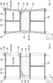
- the one-sided arrangement is conceivable both for the repair of the building supports and for the extension of the building supports 16 by means of load-bearing elements 80. It should be noted that Fig. 8 and 9 are arranged mirror-inverted to each other.
Landscapes
- Engineering & Computer Science (AREA)
- Architecture (AREA)
- Mechanical Engineering (AREA)
- Civil Engineering (AREA)
- Structural Engineering (AREA)
- Chemical & Material Sciences (AREA)
- Chemical Kinetics & Catalysis (AREA)
- Electrochemistry (AREA)
- Working Measures On Existing Buildindgs (AREA)
Applications Claiming Priority (1)
| Application Number | Priority Date | Filing Date | Title |
|---|---|---|---|
| DE102023136675.0A DE102023136675A1 (de) | 2023-12-22 | 2023-12-22 | Abstützvorrichtung, Abstützanordnung, Konsole und Verfahren zur Lasteinleitung und/oder Lastausleitung an Bauwerksstützen |
Publications (1)
| Publication Number | Publication Date |
|---|---|
| EP4582655A1 true EP4582655A1 (fr) | 2025-07-09 |
Family
ID=93926091
Family Applications (1)
| Application Number | Title | Priority Date | Filing Date |
|---|---|---|---|
| EP24221289.2A Pending EP4582655A1 (fr) | 2023-12-22 | 2024-12-18 | Dispositif de support, ensemble de support, console et procédé d'introduction de charge et/ou de sortie de charge sur des supports de construction |
Country Status (2)
| Country | Link |
|---|---|
| EP (1) | EP4582655A1 (fr) |
| DE (1) | DE102023136675A1 (fr) |
Citations (2)
| Publication number | Priority date | Publication date | Assignee | Title |
|---|---|---|---|---|
| JP2018154987A (ja) * | 2017-03-16 | 2018-10-04 | 株式会社竹中工務店 | 免震改修工法及び免震構造 |
| JP6845632B2 (ja) * | 2016-07-13 | 2021-03-17 | 大鉄工業株式会社 | 免震装置設置工法 |
Family Cites Families (4)
| Publication number | Priority date | Publication date | Assignee | Title |
|---|---|---|---|---|
| DE1751391U (de) * | 1956-12-06 | 1957-08-29 | Franz Litzka | Stuetzenartige hilfseinrichtung zur voruebergehenden lastaufnahme in bauwerken. |
| CH699432B1 (de) * | 2006-12-21 | 2010-03-15 | Stahlton Ag | Vorrichtung zur Verhinderung des Schubversagens (Durchstanzen) einer Flachdecke bzw. eines Fundamentes. |
| DE202017107261U1 (de) * | 2017-11-29 | 2019-03-01 | H-Bau Technik Gmbh | Betonfertigteil mit mindestens einem eine Last aufnehmenden Bauteil |
| CN218493192U (zh) * | 2022-10-20 | 2023-02-17 | 绍兴市景越工程设计有限公司 | 一种便于调节的加固保护装置 |
-
2023
- 2023-12-22 DE DE102023136675.0A patent/DE102023136675A1/de active Pending
-
2024
- 2024-12-18 EP EP24221289.2A patent/EP4582655A1/fr active Pending
Patent Citations (2)
| Publication number | Priority date | Publication date | Assignee | Title |
|---|---|---|---|---|
| JP6845632B2 (ja) * | 2016-07-13 | 2021-03-17 | 大鉄工業株式会社 | 免震装置設置工法 |
| JP2018154987A (ja) * | 2017-03-16 | 2018-10-04 | 株式会社竹中工務店 | 免震改修工法及び免震構造 |
Non-Patent Citations (1)
| Title |
|---|
| CHRISTOPH A BEECKEN ET AL: "Intelligente Erhaltungskonzepte: Parkgaragen nachhaltig instand setzen", BETON- UND STAHLBETONBAU, JOHN WILEY, HOBOKEN, USA, vol. 103, no. 5, 29 April 2008 (2008-04-29), pages 296 - 303, XP071152236, ISSN: 0005-9900, DOI: 10.1002/BEST.200800613 * |
Also Published As
| Publication number | Publication date |
|---|---|
| DE102023136675A1 (de) | 2025-06-26 |
Similar Documents
| Publication | Publication Date | Title |
|---|---|---|
| EP2787140B1 (fr) | Plafond plat en structure composite bois-béton et procédé de fabrication d'un tel plafond plat | |
| AT517231B1 (de) | Verfahren zur Herstellung einer Fahrbahnplatte für eine Brücke | |
| EP1983111A1 (fr) | Coffrage destiné à limiter les sections de parois moulées, élément de coffrage et procédé de fabrication d'une paroi moulée dans le sol | |
| EP2715013B1 (fr) | Ensemble d'assemblage et procédé de production d'une consolidation contre la perforation, d'un renfort de force transversale supplémentaire ou d'un raccordement d'armature | |
| EP3519641B1 (fr) | Dispositif de raccordement destiné à relier des éléments préfabriqués minces, éléments préfabriqués équipés de celui-ci, procédé de fabrication de tels éléments préfabriqués équipés d'un tel dispositif de raccordement | |
| DE102007057291A1 (de) | Verfahren zur Herstellung einer Eckverbindung für Beton-Fertigteile | |
| DE3322019C2 (de) | Verfahren zum vorübergehenden Übertragen von außerhalb der Querschnittsfläche eines Bauwerks parallel zu dessen Außenfläche wirkenden Kräften sowie Vorrichtung zum Durchführen des Verfahrens | |
| EP4582655A1 (fr) | Dispositif de support, ensemble de support, console et procédé d'introduction de charge et/ou de sortie de charge sur des supports de construction | |
| AT15902U1 (de) | Haltevorrichtung zum befestigen von brüstungselementen | |
| EP3492665A1 (fr) | Pièce préfabriquée de béton dotée d'au moins un composant recevant la charge ainsi que plaque de raccordement destinée à être agencée dans le joint de raccordement entre une telle pièce préfabriquée de béton et le composant recevant la charge | |
| DE10007450A1 (de) | Montageträgersystem sowie Verfahren zur Befestigung eines Fertigbauteils an einem Gebäudeteil unter Verwendung des Montageträgersystems | |
| EP1063361B1 (fr) | Gabarit de montage et procédé de montage d'un élément préfabriqué sur une partie de bâtiment | |
| DE69123517T2 (de) | Verfahren zur Herstellung einer Stahlblechbetondecke | |
| EP3299524B1 (fr) | Mur en elements prefabriques et son procede de fabrication | |
| AT524849B1 (de) | Montagesystem für Geländer und Absturzsicherungen | |
| DE19837080A1 (de) | Flüssigkeitsbehälter, insbesondere Klärwerksbecken, und Verfahren zur Herstellung einer Abdeckung desselben | |
| DE102011110920B4 (de) | Gebäude sowie Verfahren zu seiner Herstellung | |
| DE10017564B4 (de) | Verfahren zur Herstellung einer Bodenkonstruktion mit einer Vielzahl von höhenverstellbaren Stützen und Vorrichtung zur Positionierung dieser Stützen | |
| DE19720637C1 (de) | Verfahren zur Herstellung eines Bauteils aus Stahlbeton und Schalung zur Durchführung des Verfahrens | |
| AT519622B1 (de) | Haltevorrichtung zum befestigen von brüstungselementen | |
| DE901467C (de) | Zwei- oder mehrschalige, kreuzweis bewehrte Wand, Decke od. dgl. | |
| EP0457969B1 (fr) | Méthode et dispositif pour soulever des ouvrages | |
| DE69001688T2 (de) | Verfahren zur befestigung von horizontalen balken an stahlsaeulen eines gebaeudes und ein nach diesem verfahren errichtetes gebaeude. | |
| DE2161500B2 (de) | Verfahren und vorrichtung zur montage eines vorgespannten tragwerks aus betonfertigteilen | |
| DE2548298C2 (de) | Verfahren und Hohlraumverschalungswand zum Bauen einer Hohlmauer |
Legal Events
| Date | Code | Title | Description |
|---|---|---|---|
| PUAI | Public reference made under article 153(3) epc to a published international application that has entered the european phase |
Free format text: ORIGINAL CODE: 0009012 |
|
| STAA | Information on the status of an ep patent application or granted ep patent |
Free format text: STATUS: THE APPLICATION HAS BEEN PUBLISHED |
|
| AK | Designated contracting states |
Kind code of ref document: A1 Designated state(s): AL AT BE BG CH CY CZ DE DK EE ES FI FR GB GR HR HU IE IS IT LI LT LU LV MC ME MK MT NL NO PL PT RO RS SE SI SK SM TR |
|
| STAA | Information on the status of an ep patent application or granted ep patent |
Free format text: STATUS: REQUEST FOR EXAMINATION WAS MADE |
|
| 17P | Request for examination filed |
Effective date: 20251210 |