EP4582656A1 - Dispositif de nettoyage de piscine et son procédé de commande - Google Patents
Dispositif de nettoyage de piscine et son procédé de commande Download PDFInfo
- Publication number
- EP4582656A1 EP4582656A1 EP24201389.4A EP24201389A EP4582656A1 EP 4582656 A1 EP4582656 A1 EP 4582656A1 EP 24201389 A EP24201389 A EP 24201389A EP 4582656 A1 EP4582656 A1 EP 4582656A1
- Authority
- EP
- European Patent Office
- Prior art keywords
- cleaning device
- pool cleaning
- vector nozzle
- unit
- water
- Prior art date
- Legal status (The legal status is an assumption and is not a legal conclusion. Google has not performed a legal analysis and makes no representation as to the accuracy of the status listed.)
- Pending
Links
Images




Classifications
-
- E—FIXED CONSTRUCTIONS
- E04—BUILDING
- E04H—BUILDINGS OR LIKE STRUCTURES FOR PARTICULAR PURPOSES; SWIMMING OR SPLASH BATHS OR POOLS; MASTS; FENCING; TENTS OR CANOPIES, IN GENERAL
- E04H4/00—Swimming or splash baths or pools
- E04H4/14—Parts, details or accessories not otherwise provided for
- E04H4/16—Parts, details or accessories not otherwise provided for specially adapted for cleaning
- E04H4/1654—Self-propelled cleaners
-
- E—FIXED CONSTRUCTIONS
- E04—BUILDING
- E04H—BUILDINGS OR LIKE STRUCTURES FOR PARTICULAR PURPOSES; SWIMMING OR SPLASH BATHS OR POOLS; MASTS; FENCING; TENTS OR CANOPIES, IN GENERAL
- E04H4/00—Swimming or splash baths or pools
- E04H4/14—Parts, details or accessories not otherwise provided for
- E04H4/16—Parts, details or accessories not otherwise provided for specially adapted for cleaning
- E04H4/1654—Self-propelled cleaners
- E04H4/1663—Self-propelled cleaners the propulsion resulting from an intermittent interruption of the waterflow through the cleaner
-
- G—PHYSICS
- G05—CONTROLLING; REGULATING
- G05D—SYSTEMS FOR CONTROLLING OR REGULATING NON-ELECTRIC VARIABLES
- G05D1/00—Control of position, course, altitude or attitude of land, water, air or space vehicles, e.g. using automatic pilots
- G05D1/60—Intended control result
- G05D1/648—Performing a task within a working area or space, e.g. cleaning
-
- G—PHYSICS
- G05—CONTROLLING; REGULATING
- G05D—SYSTEMS FOR CONTROLLING OR REGULATING NON-ELECTRIC VARIABLES
- G05D2107/00—Specific environments of the controlled vehicles
- G05D2107/25—Aquatic environments
- G05D2107/29—Swimming pools
-
- G—PHYSICS
- G05—CONTROLLING; REGULATING
- G05D—SYSTEMS FOR CONTROLLING OR REGULATING NON-ELECTRIC VARIABLES
- G05D2109/00—Types of controlled vehicles
- G05D2109/30—Water vehicles
- G05D2109/38—Water vehicles operating under the water surface, e.g. submarines
Definitions
- the disclosure relates to a pool cleaning device and a corresponding control method thereof.
- a pool cleaning device is generally used for cleaning a pool, for example, get rid of garbage/debris on the bottom, side walls and/or water surface of a pool and cleaning the bottom, side walls and/or water surface of a pool, such as a swimming pool, so as to filter and purify the water in the pool.
- the filtered and purified water can be discharged into the pool, and the discharged water can be used as a thrust to the pool cleaning device, so as to provide the thrust for the pool cleaning device to travel in the water and/or on the water surface, and/or provide pressure for the pool cleaning device traveling on the wall of the pool so that the pool cleaning device can be stably attached to the wall of the pool when in a vertical orientation.
- a pool cleaning device which comprises a fluid ejecting unit comprising a fluid channel through which water flows and a vector nozzle, wherein an inlet of the vector nozzle is rotatably connected with the fluid channel; a first driving unit configured to drive water to be ejected from an outlet of the vector nozzle via the fluid channel; a housing, wherein at least two discharge openings are arranged on the housing, the two discharge openings configured to discharge the water ejected from the outlet of the vector nozzle to outside of the pool cleaning device; and a second driving unit configured to drive the vector nozzle to rotate so that the outlet of the vector nozzle is at least partially aligned with one of the at least two discharge openings.
- the pool cleaning device further comprises a waterflow guiding unit configured to guide the water ejected from the outlet of the vector nozzle to one of the at least two discharge openings.
- the waterflow guiding unit comprises at least two water conduits, and the outlet of the vector nozzle is configured to be at least partially aligned with an inlet of one of the at least two water conduits after the vector nozzle is rotated.
- the outlets of the at least two water conduits are at least partially aligned with the at least two discharge openings respectively.
- the second driving unit is configured to drive the vector nozzle to rotate based on an operation requirement or motion state of the pool cleaning device.
- the pool cleaning device further comprises a transmission unit coupled between the vector nozzle and the second driving unit; wherein, the second driving unit is configured to drive the vector nozzle to rotate via the transmission unit.
- a sealing member is arranged on the outlet of the vector nozzle or on at least one inlet of the at least two water conduits.
- the at least two discharge openings comprise a first discharge opening with discharging in a first direction, a second discharge opening with discharging in a second direction, and a third discharge opening with discharging in a third direction.
- the first direction, the second direction and the third direction are located on a same plane.
- a duration in which the second driving unit drives the vector nozzle to rotate is set as a time threshold.
- At least one pair of the fluid ejecting units and the corresponding discharge openings are symmetrically arranged on both sides of a longitudinal axis of a body of the pool cleaning device.
- At least one of the at least two discharge openings is provided with a detachable grid plate.
- orientation and/or position relationships which are indicated by the terms such as center, longitudinal direction, lateral direction, length, width, thickness, top, bottom, front, back, left, right, vertical, horizontal, top, bottom, interior, exterior, clockwise, anti-clockwise, axial, radial, circumferential, one side, the other side and etc. refer to the orientation or position relationships illustrated in the drawings, which is only for the convenience of describing the present disclosure and simplifying the description, and does not indicate or imply that the device or element must have a specific orientation, be constructed or operated in a specific orientation, and thus it should not be interpreted to make any limitations on the present disclosure.
- Fig. 1A schematically illustrates the appearance of a pool cleaning device 100 according to an embodiment of the present disclosure.
- the pool cleaning device can clean the bottom, wall, water and water surface of a pool (such as a swimming pool) as needed, for example, to get rid of the garbage in the water, on bottom and water surface, and remove the dirt on the bottom and sidewall of the pool.
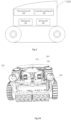
- the pool cleaning device 100 may include a housing 110, a traveling unit 120, a cleaning unit 130 and other structures/components.
- the pool cleaning device 100 may further include a buoyancy adjusting unit (not illustrated), so that the pool cleaning device can adjust its depth in the water as required, for example, it can float on the water surface, dive into the water, and sink to the bottom of the water, so as to carry out the cleaning operation on the water surface, in the water or on the bottom of the water.
- a buoyancy adjusting unit not illustrated
- a control bin, a power bin and a filter bin can be arranged in the housing 100, wherein control circuits such as a microprocessor, a digital signal processor (DSP) and a microcontroller can be arranged in the control bin, drive units such as a water pump and a drive motor can be arranged in the power bin, and a filter unit can be arranged in the filter bin, so as to filter and purify the water entering the filter bin through an inlet, and filter out debris therein; the filtered water is discharged from the pool cleaning device via outlet(s) to the pool.
- control circuits such as a microprocessor, a digital signal processor (DSP) and a microcontroller can be arranged in the control bin
- drive units such as a water pump and a drive motor can be arranged in the power bin
- a filter unit can be arranged in the filter bin, so as to filter and purify the water entering the filter bin through an inlet, and filter out debris therein; the filtered water is discharged from the pool cleaning device via
- the traveling unit 120 may include crawler traveling units on both sides of the lower part of the pool cleaning device 100, so that the pool cleaning device can travel in the water, on the bottom of the pool, or on the wall of the pool, so as to perform corresponding cleaning operations.
- the traveling unit is not limited to the travelling unit of the type illustrated in Fig. 1A , but may include, for example, a wheeled traveling unit, which is not limited herein.
- Fig. 1A also illustrates discharging openings 140 symmetrically arranged on the rear side of the housing 110 of the pool cleaning device 100 with respect to the longitudinal axis of the body of the pool cleaning device, and discharging openings 150 symmetrically arranged on the top of the housing 110 with respect to the longitudinal axis of the body of the pool cleaning device; and Fig. 1B further illustrates one of the discharging openings 160 symmetrically arranged at the front side of the housing 110 of the pool cleaning device 100.
- the discharging openings 140-160 may be mesh-like or grid-like as required, so as to discharge the water filtered and cleaned by the pool cleaning device into the pool.
- a detachable grid/mesh board such as a detachable board with grid/mesh for discharging the water or a detachable waterflow guiding plate, may be provided on any one of the discharge openings 140-160.
- the pool cleaning device 100 can use the fluid ejecting unit as an auxiliary traveling unit, so that the pool cleaning device can be pushed to travel on the water surface, in the water, on the bottom and/or the wall of the pool by using the reaction force generated by the water ejected from the nozzle of the fluid ejecting unit.
- the water ejected from the nozzle can be guided to one of the discharge openings 140-160 provided on the housing 110 of the pool cleaning device 100, thereby generating thrust in different directions.
- the pool cleaning device 100 when the water ejected from the nozzle is guided to the discharge opening(s) 140 arranged at the rear side of the housing 110 and discharged, the pool cleaning device 100 can generate a forward thrust parallel to the longitudinal axis of the body of the pool cleaning device to push the pool cleaning device 100 to move forward; when the water ejected from the nozzle is guided to the discharge opening(s) 160 arranged at the front side of the housing 110 and discharged, the pool cleaning device 100 can generate a backward thrust parallel to the longitudinal axis of the body of the pool cleaning device, and push the pool cleaning device 100 to move backward; when the water ejected from the nozzle is guided to the discharge opening(s) 150 arranged at the top of the housing 110 and discharged, the pool cleaning device 100 can generate a downward thrust perpendicular to the bottom plane of the body of the pool cleaning device, thereby applying a pressure towards the bottom of the pool cleaning device 100,wherein such a pressure can be used not only as the power
- FIGs. 1A-1B illustrate an overall appearance of the pool cleaning apparatus of the embodiment of the present disclosure. It should be understood that this is only schematic and does not constitute any limitation of the principles of the present disclosure. For example, the position, shape and/or number of the outlets 140-160 provided on the housing 110 of the pool cleaning device 100 can be adjusted according to the actual operation requirements of the pool cleaning device, and there is no limitation here.
- the water ejected from the fluid ejecting unit can be guided to the corresponding discharging openings, so that the traveling direction of the pool cleaning device is not limited to the horizontal and/or vertical direction, but also can be an inclined direction at a certain angle with the vertical direction.
- the position, shape and/or number of the discharging openings on the housing of the pool cleaning device can be set according to the specific application situation, size and other related factors.
- pool cleaning device 100 illustrated in Figs. 1A-1B is only an example, and one or more aspects such as appearance, structure, layout, components, functions, etc. can be changed by those skilled in the art according to actual needs without departing from the principles of the present disclosure.
- the direction of the outlet of the nozzle can be controlled to be parallel to the longitudinal axis of the body of the pool cleaning device, for example, forward/backward direction of the pool cleaning device, so as to generate a thrust for the pool cleaning device to travel.
- the motion state can include steering, extricating, accelerating, decelerating, sudden braking, special motion path and etc., and can include any motion state that needs to change the direction of the thrust generated by the nozzle.
- the driving unit 220 of the pool cleaning device may further include a second driving unit 340.
- the second driving unit 340 may drive the vector nozzle 360 to rotate so that the outlet of the vector nozzle is at least partially aligned with at least one outlet of the waterflow guiding unit.
- the second driving unit 340 can drive the vector nozzle 360 to rotate based on the operation requirement or motion state of the pool cleaning device. For example, as described above, when the pool cleaning device needs to be switched from the bottom operation to the cleaning operation or traveling on the pool wall, the vector nozzle 360 as illustrated in Fig. 3D can be controlled to rotate at a proper timing, so that its outlet is aligned with the outlet 380 of the waterflow guiding unit as illustrated in Fig. 3B , so that the water ejected from the fluid ejecting unit can be guided to the discharge openings 150 on both sides of the top of the housing of the pool cleaning device, thereby generating a thrust perpendicular to the plane of the bottom of the pool cleaning device and towards the bottom of the pool cleaning device.
- the vector nozzle 360 as illustrated in Fig. 3D can be controlled to rotate at a proper timing, so that its outlet is switched from being aligned with the outlet 380 to being aligned with the outlet 370 or 390 of the waterflow guiding unit as illustrated in Fig.3B , so that the water ejected from the fluid ejecting unit can be guided to the discharge openings 140 or 160 on both sides of the housing of the pool cleaning device along the longitudinal axis of the body, thereby generating a thrust along the longitudinal axis of the body for the forward/backward movement.
- first direction and the third direction are parallel to the longitudinal axis of the body of the pool cleaning device, and the second direction is vertical and upward to the plane where the bottom of the body of the pool cleaning device is located. That is, the first direction and the third direction are opposite, and the second direction is perpendicular to the first and third directions.
- the first direction, the second direction and the third direction are located on the same plane.
- the second driving unit 340 may control the motor to drive the vector nozzle 360 to rotate based on the received control signal, for example, so that the outlet of the vector nozzle is rotated from the first direction to the second direction, or from the first direction to the third direction via the second direction.
- the water ejecting speed of the vector nozzle in different directions can also be adjusted accordingly.
- the second driving unit 340 may adopt various driving strategies in which, for example, the duration in which the second driving unit drives the vector nozzle 360 to rotate may be set as a time threshold.
- the time threshold may be set not to exceed 3S.
- the second driving unit 340 may control the motor to drive the vector nozzle 360 to rotate so that the outlet of the vector nozzle is rotated from the first direction to the third direction via the second direction, instead of continuously driving, and the motor pauses for a few seconds when the second direction is arrived, and then continue to drive the vector nozzle 360 to rotate until its outlet direction is aligned with the third direction.
- the second driving unit 340 may control the motor to drive the vector nozzle 360 to rotate so that the outlet of the vector nozzle is rotated from the first direction to the third direction via the second direction, instead of continuously driving, and the motor pauses for a few seconds when the second direction is arrived, and then continue to drive the vector nozzle 360 to rotate until its outlet direction is aligned with the third direction.
- the pool cleaning device may further include a transmission unit 330.
- the vector nozzle can be driven to rotate by the second driving unit 340 illustrated in Fig. 3D via the transmission unit 330, so that the direction of outlet of the vector nozzle is at least partially aligned with one of the outlets 370, 380 or 390 of the waterflow guiding unit illustrated in Fig. 3B or Fig. 3C , and then the water can be discharged from the pool cleaning device via the discharge opening(s) 140, 150 or 160 on the housing of the pool cleaning device, thus generating a thrust for the pool cleaning device to travel in the corresponding direction.
- the transmission unit 330 is coupled between the vector nozzle 360 and the second driving unit 340; the second driving unit 340 drives the vector nozzle 360 to rotate via the transmission unit 330.
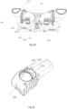
- the transmission unit 330 includes a first set of gears including a first gear 3310 and a second gear 3320, wherein the first gear 3310 is arranged on the vector nozzle 360 and the second gear 3320 meshes with the first gear 3310.
- the transmission unit 330 further includes a second set of gears including a third gear 3330 and a fourth gear 3340, wherein the third gear 3330 and the second gear 3320 are installed on a rod, and the fourth gear 3340 meshes with the third gear 3330; the fourth gear 3340 is driven by the second driving unit 340.
- the fourth gear 3340 is driven by the second driving unit 340 to rotate, and the third gear 3330 is driven to rotate by the engagement between the fourth gear 3340 and the third gear 3330.
- the third gear 3330 and the second gear 3320 are installed on the same rod, the rotation of the third gear 3330 will be transmitted to the second gear 3320 through the rod, and finally the vector nozzle 360 will be driven to rotate through the rotation of the second gear 3320 and the engagement between the second gear 3320 and the first gear 3310.
- the second driving unit 340 can finally drive the vector nozzle 360 to rotate through the transmission of the transmission unit 330.
- the third gear 3330 and the fourth gear 3340 may be bevel gears.
- transmission unit 330 illustrated in Figs. 3B and 3D is only an example of an embodiment of the present disclosure, and the principles of the present disclosure are not limited thereto. In fact, those skilled in the art can devise other transmission unit which adopts different structures and can also drive the vector nozzle 360 to rotate under the driving of the second driving unit 340 according to actual needs.
- each fluid ejecting unit can be separately equipped with a corresponding driving unit and transmission unit, that is, each vector nozzle can be separately equipped with a corresponding driving unit and transmission unit, instead of two vector nozzles sharing a driving unit and a transmission unit as illustrated in Figures 3A-3D .
- the vector nozzle 560 of each fluid ejecting unit can be equipped with a separate driving unit 540 and a corresponding transmission unit 530. That is, the vector nozzle of each fluid ejecting unit can be driven independently to rotate.
- each fluid ejecting unit may share a first driving units (not illustrated); in this case, corresponding valves can be arranged in the fluid channels of the two fluid ejecting units respectively, and the volume/velocity of waterflow in the two fluid channels can be adjusted by controlling the extent to which the valves in the respective fluid channels is open/closed, so as to control the water ejected from the nozzles of the two fluid ejecting units respectively.
- the pool cleaning device may further include a direction determining unit for determining the direction of the outlet of the vector nozzle.
- the second driving unit may drive the vector nozzle to rotate.
- the pool cleaning device can include a direction determining unit for determining the direction of the outlet of the vector nozzle.
- the direction determining unit can be realized as a sensor which detects the direction of the outlet of the vector nozzle, or can obtain the information about the rotation of the vector nozzle recorded by the pool cleaning device.
- a signal transmitting component can be arranged on one of the vector nozzle and the fluid channel of the fluid ejecting unit, and a corresponding signal receiving component can be arranged on the other of the vector nozzle and the fluid channel, so as to receive signals emitted by the signal transmitting component, thus determining the relative positional relationship between the direction of the outlet of the vector nozzle and that of the fluid channel (for example, the direction of the outlet of the fluid channel), and further determining the specific position of the outlet direction of the vector nozzle.
- the signal transmitting component is a magnetic component
- the signal receiving component is a Hall sensor
- the signal transmitting component is an infrared emitting component
- the signal receiving part is an infrared receiving component
- a position detecting component such as a photoelectric encoder, a resolver
- the output signals are fed back to a processing unit/control unit of the pool cleaning device, and are used as information about the rotation of the vector nozzle to be recorded by the pool cleaning device, so that the corresponding control instructions can be sent to the second driving unit through the processing unit/control unit of the pool cleaning device to drive the vector nozzle to rotate towards a target direction, for example, to align with one of the outlets of the waterflow guiding unit.
- the vector nozzle is driven to rotate by the second driving unit of the pool cleaning device, so that the direction of the water ejected from the fluid ejecting unit of the pool cleaning device can be changed, and the water ejected from the fluid ejecting unit can be guided to the corresponding discharging opening on the housing of the pool cleaning device via the waterflow guiding unit arranged in the pool cleaning device, thus providing a thrust for the pool cleaning device in different directions.
- the first driving unit of the pool cleaning device the volume and/or velocity of waterflow via the fluid channel and the vector nozzle of the fluid ejecting unit can be controlled, thus controlling a magnitude of the thrust provided for the pool cleaning device.
- a method for controlling the pool cleaning device includes: S610, driving water to be ejected from the vector nozzle of the pool cleaning device; and S620, based on an operation requirement or motion state of the pool cleaning device, controlling the vector nozzle to rotate so as to guide the water ejected from the vector nozzle to one of a plurality of outlets in different directions of the pool cleaning device and discharge the water from the pool cleaning device.
- the direction and magnitude of the thrust provided for the pool cleaning device can be controlled, and make it convenient for the pool cleaning device to perform various cleaning operations, and the traveling direction and posture can be changed as required.
- the principle of this disclosure is also applicable to the case where the discharge opening(s) is arranged at the bottom of the housing of the pool cleaning device, and the direction of the discharge opening(s) can be perpendicular to the plane where the bottom of the pool cleaning device is located.
- the water ejected from the fluid ejecting unit can be guided downward to the direction perpendicular to the plane where the bottom of the pool cleaning device is located, thus generating an upward thrust for the pool cleaning device.
Landscapes
- Engineering & Computer Science (AREA)
- Architecture (AREA)
- Civil Engineering (AREA)
- Structural Engineering (AREA)
- Aviation & Aerospace Engineering (AREA)
- Radar, Positioning & Navigation (AREA)
- Remote Sensing (AREA)
- Physics & Mathematics (AREA)
- General Physics & Mathematics (AREA)
- Automation & Control Theory (AREA)
- Cleaning By Liquid Or Steam (AREA)
Applications Claiming Priority (2)
| Application Number | Priority Date | Filing Date | Title |
|---|---|---|---|
| PCT/CN2024/070969 WO2025145455A1 (fr) | 2024-01-05 | 2024-01-05 | Appareil de nettoyage d'eau et mécanisme de pulvérisation d'eau |
| CN202411011435.6A CN118950641A (zh) | 2024-01-05 | 2024-07-24 | 水池清洁装置及其相应的控制方法 |
Publications (1)
| Publication Number | Publication Date |
|---|---|
| EP4582656A1 true EP4582656A1 (fr) | 2025-07-09 |
Family
ID=92883148
Family Applications (1)
| Application Number | Title | Priority Date | Filing Date |
|---|---|---|---|
| EP24201389.4A Pending EP4582656A1 (fr) | 2024-01-05 | 2024-09-19 | Dispositif de nettoyage de piscine et son procédé de commande |
Country Status (3)
| Country | Link |
|---|---|
| US (1) | US20250223826A1 (fr) |
| EP (1) | EP4582656A1 (fr) |
| AU (1) | AU2024287129B2 (fr) |
Families Citing this family (1)
| Publication number | Priority date | Publication date | Assignee | Title |
|---|---|---|---|---|
| USD1109463S1 (en) * | 2024-01-31 | 2026-01-13 | Suzhou Smorobot Technology Co., Ltd. | Robotic pool cleaner |
Citations (4)
| Publication number | Priority date | Publication date | Assignee | Title |
|---|---|---|---|---|
| EP2848751A1 (fr) * | 2013-09-11 | 2015-03-18 | Maytronics Ltd. | Robot de nettoyage de piscine ayant des capacités de mouvement à ligne de flottaison |
| US20150143643A1 (en) * | 2012-05-28 | 2015-05-28 | Electronics & Pool Accessories Import | Device for cleaning a submerged surface with a propelled water jet |
| US20160060887A1 (en) * | 2014-09-03 | 2016-03-03 | Maytronics Ltd. | Pool cleaning robot and a method for cleaning a pool |
| US20190032356A1 (en) * | 2017-07-31 | 2019-01-31 | Maytronics Ltd. | Pool cleaning robot with directional jet thrusts |
-
2024
- 2024-09-19 EP EP24201389.4A patent/EP4582656A1/fr active Pending
- 2024-10-22 US US18/922,969 patent/US20250223826A1/en active Pending
- 2024-12-20 AU AU2024287129A patent/AU2024287129B2/en active Active
Patent Citations (4)
| Publication number | Priority date | Publication date | Assignee | Title |
|---|---|---|---|---|
| US20150143643A1 (en) * | 2012-05-28 | 2015-05-28 | Electronics & Pool Accessories Import | Device for cleaning a submerged surface with a propelled water jet |
| EP2848751A1 (fr) * | 2013-09-11 | 2015-03-18 | Maytronics Ltd. | Robot de nettoyage de piscine ayant des capacités de mouvement à ligne de flottaison |
| US20160060887A1 (en) * | 2014-09-03 | 2016-03-03 | Maytronics Ltd. | Pool cleaning robot and a method for cleaning a pool |
| US20190032356A1 (en) * | 2017-07-31 | 2019-01-31 | Maytronics Ltd. | Pool cleaning robot with directional jet thrusts |
Also Published As
| Publication number | Publication date |
|---|---|
| AU2024287129A1 (en) | 2025-07-24 |
| AU2024287129B2 (en) | 2026-04-23 |
| US20250223826A1 (en) | 2025-07-10 |
Similar Documents
| Publication | Publication Date | Title |
|---|---|---|
| US11939791B2 (en) | Controlling a movement of a pool cleaning robot | |
| EP4582656A1 (fr) | Dispositif de nettoyage de piscine et son procédé de commande | |
| US10407930B2 (en) | Automatic electric top bottom swimming pool cleaner with internal pumps | |
| CN115542922B (zh) | 一种泳池清洁机器人及控制方法、电子设备与存储介质 | |
| CN108423141B (zh) | 一种水下作业机器人及其控制方法 | |
| EP3842604B1 (fr) | Nettoyeur de piscine | |
| CN117052204A (zh) | 一种水池清洁机器人及其控制方法 | |
| US12392157B1 (en) | Water surface cleaning apparatus | |
| CN118950641A (zh) | 水池清洁装置及其相应的控制方法 | |
| CN119531642A (zh) | 控制水池清洁装置的方法以及相应的水池清洁装置 | |
| US20240122429A1 (en) | Electric robot | |
| CN220036259U (zh) | 一种泳池清洗机器人 | |
| CN116290950B (zh) | 一种喷水推进式泳池机器人及其控制方法 | |
| CN116043796A (zh) | 一种漂浮式河道垃圾收集装置及使用方法 | |
| CN112536300A (zh) | 一种水族馆水池清洗装置 | |
| CN118749488A (zh) | 一种循环水养殖池底清污机器人及其清污控制方法 | |
| CN117536483A (zh) | 水面清洁机器人及其控制方法 | |
| CN208630731U (zh) | 一种疏浚机器人全自动履带结构 | |
| CN120631002A (zh) | 水池自动清洁装置及其脱困方法 | |
| CN121523335A (zh) | 水池自动清洁装置及其控制方法 | |
| CN220721365U (zh) | 一种防止入水后姿态失衡的水下清洁机器人 | |
| CN119311000A (zh) | 一种控制方法及应用其的水下清洁机器人 | |
| CN213921434U (zh) | 一种新型结构的水下无人机 | |
| CN121952372A (zh) | 水池自动清洁装置 | |
| CN121956981A (zh) | 控制水池自动清洁装置的方法以及相应的水池自动清洁装置 |
Legal Events
| Date | Code | Title | Description |
|---|---|---|---|
| PUAI | Public reference made under article 153(3) epc to a published international application that has entered the european phase |
Free format text: ORIGINAL CODE: 0009012 |
|
| STAA | Information on the status of an ep patent application or granted ep patent |
Free format text: STATUS: THE APPLICATION HAS BEEN PUBLISHED |
|
| AK | Designated contracting states |
Kind code of ref document: A1 Designated state(s): AL AT BE BG CH CY CZ DE DK EE ES FI FR GB GR HR HU IE IS IT LI LT LU LV MC ME MK MT NL NO PL PT RO RS SE SI SK SM TR |
|
| STAA | Information on the status of an ep patent application or granted ep patent |
Free format text: STATUS: REQUEST FOR EXAMINATION WAS MADE |
|
| 17P | Request for examination filed |
Effective date: 20251231 |