EP4582665A2 - Ensemble porte ayant un panneau de porte à fond souple - Google Patents
Ensemble porte ayant un panneau de porte à fond souple Download PDFInfo
- Publication number
- EP4582665A2 EP4582665A2 EP25178304.9A EP25178304A EP4582665A2 EP 4582665 A2 EP4582665 A2 EP 4582665A2 EP 25178304 A EP25178304 A EP 25178304A EP 4582665 A2 EP4582665 A2 EP 4582665A2
- Authority
- EP
- European Patent Office
- Prior art keywords
- door panel
- drive
- column
- teeth
- tooth
- Prior art date
- Legal status (The legal status is an assumption and is not a legal conclusion. Google has not performed a legal analysis and makes no representation as to the accuracy of the status listed.)
- Pending
Links
Images







Classifications
-
- E—FIXED CONSTRUCTIONS
- E06—DOORS, WINDOWS, SHUTTERS, OR ROLLER BLINDS IN GENERAL; LADDERS
- E06B—FIXED OR MOVABLE CLOSURES FOR OPENINGS IN BUILDINGS, VEHICLES, FENCES OR LIKE ENCLOSURES IN GENERAL, e.g. DOORS, WINDOWS, BLINDS, GATES
- E06B9/00—Screening or protective devices for wall or similar openings, with or without operating or securing mechanisms; Closures of similar construction
- E06B9/56—Operating, guiding or securing devices or arrangements for roll-type closures; Spring drums; Tape drums; Counterweighting arrangements therefor
- E06B9/58—Guiding devices
- E06B9/581—Means to prevent or induce disengagement of shutter from side rails
-
- E—FIXED CONSTRUCTIONS
- E06—DOORS, WINDOWS, SHUTTERS, OR ROLLER BLINDS IN GENERAL; LADDERS
- E06B—FIXED OR MOVABLE CLOSURES FOR OPENINGS IN BUILDINGS, VEHICLES, FENCES OR LIKE ENCLOSURES IN GENERAL, e.g. DOORS, WINDOWS, BLINDS, GATES
- E06B9/00—Screening or protective devices for wall or similar openings, with or without operating or securing mechanisms; Closures of similar construction
- E06B9/02—Shutters, movable grilles, or other safety closing devices, e.g. against burglary
- E06B9/08—Roll-type closures
- E06B9/11—Roller shutters
- E06B9/13—Roller shutters with closing members of one piece, e.g. of corrugated sheet metal
-
- E—FIXED CONSTRUCTIONS
- E06—DOORS, WINDOWS, SHUTTERS, OR ROLLER BLINDS IN GENERAL; LADDERS
- E06B—FIXED OR MOVABLE CLOSURES FOR OPENINGS IN BUILDINGS, VEHICLES, FENCES OR LIKE ENCLOSURES IN GENERAL, e.g. DOORS, WINDOWS, BLINDS, GATES
- E06B9/00—Screening or protective devices for wall or similar openings, with or without operating or securing mechanisms; Closures of similar construction
- E06B9/56—Operating, guiding or securing devices or arrangements for roll-type closures; Spring drums; Tape drums; Counterweighting arrangements therefor
- E06B9/58—Guiding devices
- E06B2009/583—Cords or cables
-
- E—FIXED CONSTRUCTIONS
- E06—DOORS, WINDOWS, SHUTTERS, OR ROLLER BLINDS IN GENERAL; LADDERS
- E06B—FIXED OR MOVABLE CLOSURES FOR OPENINGS IN BUILDINGS, VEHICLES, FENCES OR LIKE ENCLOSURES IN GENERAL, e.g. DOORS, WINDOWS, BLINDS, GATES
- E06B9/00—Screening or protective devices for wall or similar openings, with or without operating or securing mechanisms; Closures of similar construction
- E06B9/56—Operating, guiding or securing devices or arrangements for roll-type closures; Spring drums; Tape drums; Counterweighting arrangements therefor
- E06B9/68—Operating devices or mechanisms, e.g. with electric drive
- E06B9/70—Operating devices or mechanisms, e.g. with electric drive comprising an electric motor positioned outside the roller
Definitions
- the present invention is directed to a door assembly and related components, wherein the door assembly includes a soft bottomed door panel and a system for driving the same.
- Overhead roll-up door assemblies like those found in U.S. Pat. No. 8,607,842 typically include a flexible door panel which is guided within side columns and/or guide tracks positioned on opposite sides of a doorway as the flexible door panel is opened and closed.
- a drum and motor combination is typically provided, with the door panel being fixed at one end to the drum.
- the motor is typically mechanically coupled to the drum so that activation of the motor in a first direction causes the drum to rotate in a first direction, and activation of the motor in a second, reverse, direction causes the drum to rotate in a second direction.
- the first direction for example, the door panel will begin winding up on the drum, opening the doorway which was previously blocked by the door panel.
- the second direction for example, the door panel will unwind from the drum, blocking the previously open doorway.
- a weighted bottom bar is attached to a lower end of the door panel so that the door panel remains taut in the guide tracks and doorway opening.
- Weighted bottom bars - along with thickened bodies placed proximate each lateral edge of the door panel - also help prevent wind pressure on one side of the door panel, or pressure differentials on opposing sides of the door panel, from causing the door panel to disengage the guide tracks as it opens, closes, or stops and remains static in a partially or fully closed position.
- weighted bottom bars are successful in facilitating the opening and closing of overhead roll-up door panels, and, along with thickened bodies along the edges in preventing such door panels from disengaging with associated guide tracks as a result of a wind load on one side of the door panel or pressure differential on opposing sides of the door panel, weighted bottom bars may cause damage if the door panel is closed on a person or object located beneath the panel.
- Safety systems have been developed in order to prevent such occurrences, however it would be advantageous to have a door assembly which utilizes a door panel which does not have a weighted bottom bar, but instead has a soft bottom edge while maintaining the tautness within the panel as the door opens and closes, as well as maintaining the wind load benefits realized from the use of a weighted bottom bar.
- a door assembly includes a door panel having a top edge, a bottom edge, a first vertical edge and a second vertical edge.
- the top edge of the door panel (and/or some portion of the door panel proximate thereto) is permanently fixed to a drum, with the drum being rotatable in a first direction and a second direction. Rotation of the drum in the first direction causes the door panel to wind onto the drum (open the door), while rotation of the drum in the second, opposite, direction causes the door panel to unwind from the drum (close the door).
- the door assembly further comprises a first side column and a second side column, wherein the first side column is positioned proximate a first side of a doorway which is opened and closed by the door panel, and the second side column is positioned proximate a second side of the doorway.
- Each of the first side column and the second side column include a guide track. Each guide track is positioned to guide one of the first vertical edge or the second vertical edge of the door panel as it opens and closes the doorway.
- a first column of drive teeth is positioned along the first vertical edge of the door panel, and a second column of drive teeth is positioned along the second vertical edge of the door panel, wherein each of the first column of drive teeth and the second column of drive teeth are formed by a plurality of adjacent individual drive teeth, with each drive tooth in each column abutting an adjacent drive tooth as the door panel is wound and unwound from the drum.
- the door assembly may further include a first drive sprocket being positioned proximate a top of the first side column and guide track (adjacent or located in close proximity above, and/or offset from, the top of the first side column and guide track) and a second drive sprocket positioned proximate a top of the second side column and guide track.
- the first drive sprocket may be positioned to engage the first column of drive teeth
- the second drive sprocket may be positioned to engage the second column of drive teeth, as the door panel is wound and unwound from the drum.
- the drive sprockets may be connected by a second drum, with at least one of the drive sprockets and/or the drum being connected to a motor to rotate and drive sprockets and drum.
- each drive tooth in the first column of drive teeth and the second column of drive teeth may include an opening formed in the outer surface of the drive tooth.
- the opening in each drive tooth may provide access to an open channel extending vertically through the middle of the drive tooth, the opening and vertical channel being configured to facilitate engagement of each drive tooth with the first or second vertical edge of the door panel, while providing an opening and channel through which each individual drive tooth can be disengaged and removed from the door panel if necessary.
- each drive tooth may be rounded.
- the bottom portion of each drive tooth in addition to or in the alternative of being flat, may include a projection which abuts and engages an adjacent flat top portion in order to create a further upwards and/or downwards force within the column of drive teeth.
- each drive tooth in the first column of drive teeth and the second column of drive teeth may also further include an angled or second planar top portion and an angled or second planar bottom portion.
- the angled top potion of each drive tooth may connect to the flat top portion, and extend in a plane at an angle thereto, at a top pivot point.
- the angled bottom portion of each drive tooth may connect to the flat bottom portion, and extend in a plane at an upward angle to the flat portion from a bottom pivot point.
- each drive tooth By providing a plurality of gaps in each column of drive teeth, a space is provided for each drive tooth to pivot and contact the adjacent drive tooth when the drive tooth columns are wound on the drum or flexed around a drive sprocket. At least a substantial portion of the plurality of gaps, i.e. at least all the teeth which are wound on the drum, are closed and each of the top angled portion and the bottom angled portion of each adjacent drive tooth in each drive tooth column abut each other when the door panel is substantially wound on the drum, i.e. the door panel is mostly or completely open.
- the door assembly may further include a first drive guide and a second drive guide to help facilitate proper (and aligned) engagement between the drive teeth and the guide sprockets.
- the first drive guide may partially surround the first guide sprocket and facilitate engagement between the first column of drive teeth and the first guide sprocket
- the second drive guide may partially surround the second guide sprocket and facilitate engagement between the second column of drive teeth and the second guide sprocket.
- the guide track of the first side column and the guide track of the second side column of the door assembly may each include a first track and a second track, with each side column further including a track holder.
- Each track holder may include a first support and a second support, with the first support of each track holder being coupled to the first track of the guide track of the respective side column, and the second support being coupled to the second track of the guide track of the respective side column.
- Each track holder support may be made from a material more rigid than the first track and the second track.
- the first track and the second track of each guide track may extend laterally towards the interior of the doorway a first distance
- the first support and the second support of each track holder of each side column may extend laterally towards the interior of the doorway a second distance, wherein the first distance is greater than the second distance so that each track holder only partially overlaps the attached track.
- the first track and the second track of each of the first and second drive tracks may include a curved portion, the curved portions defining a gap through which the door panel extends from the guide track into the doorway opening.
- the curved portions may each include a curved seat.
- the curved seat may match a geometry of each drive tooth in the first column of drive teeth and the second column of drive teeth. For example, the matching geometry may create a ball and socket interface.
- the first guide track and the second guide track may be constructed from flexible materials.
- the first guide track and the second guide track may be constructed using ultra-high molecular weight plastic or polymer.
- each drive tooth in the first column of drive teeth and each drive tooth in the second column of drive teeth may be fastened to the vertical edge of the door panel and/or any Keder positioned proximate the vertical edge, by a fastener.
- counterweight 27 may be provided within the side column 18 and connected to drum 14 using strap 21.
- a first end of strap 21 may connect to a spool or pulley 23 at the end of drum 14. Strap 21 may then be guided around pulley 25, before connecting at a second end to a counterweight 27 housed within side column 18.
- Drum 14 and drum 17 may be configured to rotate in the same direction when opening or closing the door panel, with strap 21 being wound about spool 23 and pulley 25 in a manner which accommodates this rotation.
- drum 14 may be configured and attached to the door panel in a manner in which drum 14 rotates in the first, counterclockwise direction to wind up door panel 12 onto drum 14 and open the door.
- drum 17 rotates
- drive sprockets 110, 112 lower the door panel to the closed position, unwinding the door panel from drum 14.
- the force of the motor driving door panel 12 downwards causes drum 14 to rotate in the clockwise direction as the door panel is unwound from drum 14, and since spool 23 is coupled directly to and rotates with drum 14, this rotation causes strap 21 to rewind on the spool 23 and consequently raises counterweight 27.
- the motor is both rotating drive sprockets 110, 112 and drum 17 to lower the door panel, and providing the force to rotate drum 14 which is coupled to drum 17 by door panel 12, with the rotation of drum 14 raising counterweight 27.
- counterweight 27 helps maintain a tautness in the door panel, as it provides some resistance to the clockwise rotation of drum 14 so that the door panel is unwound in a more controlled manner.
- clockwise and counterclockwise directions can be reversed. Such is different from standard overhead roll-up door assemblies wherein the motor is typically used to drive the drum on which the door panel is wound to open the door panel.
- Door panel 12 can be more clearly seen in FIG. 2 , which shows the door panel 12 from FIGs. 1A and 1B isolated and removed from door assembly 10.
- door panel 12 includes a top edge 20, a bottom or leading edge 22, and opposing vertical side edges 24, 26 which extend between the top edge and the bottom edge.
- the opposing vertical side edges extend into and are guided by the guide tracks within side columns 16, 18 when the door panel is integrated with a door assembly as in FIG. 1A and FIG. 1B . While top edge 20 is shown free in FIG.
- bottom edge 22 may be constructed or formed using the door panel material itself, a combination of door panel material and/or other fabric and/or other light weight or non-weighted and non-rigid material, and/or may include a cord or wire cable. Regardless of how bottom edge 22 is formed, the bottom edge will lead the door panel as it is closed, for example, and contact the floor or bottom edge of the doorway when in the door panel is in the fully closed position.
- each of the columns of drive teeth 28, 30 are shown in FIG. 2 as extending substantially along the entirety of its respective vertical edge, such is not necessary in order to realize the advantages of the present invention. It is contemplated that each column of drive teeth may stop short of top edge 20, and may, for example, only extend along a substantial portion of the vertical edge and not extend to some portion of the door panel which extends above the side columns when the door panel is fully closed.
- drive sprockets or drive gears 110, 112 are incorporated into the drive assembly above the side columns and guide tracks, as is shown in FIGs.
- the drive tooth columns may extend beyond the side columns and guide tracks to the drive sprockets or gears when the door panel is fully closed, but may only extend beyond the drive sprockets or gears a short distance, i.e. one or two teeth beyond the number of teeth required to maintain engagement of the drive tooth column with the drive sprocket or gear when the door panel is fully closed.
- the remainder of each vertical edge of the door panel between the few teeth located above or past the drive sprocket and the top edge of the door panel may not have any drive teeth engaged therewith.
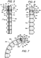
- the second effect of the continuous column of drive teeth on each vertical edge is, if the individual teeth are properly configured, the column of teeth will enhance the rigidity and stiffness of the unwound portion of the door panel by, for example, preventing the door panel from being wound or bent in one direction, i.e. towards the non-toothed portion or in direction H in FIG. 5 as the abutting drive teeth will prevent flexing of the column in that direction.
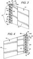
- each drive tooth extends in the same direction, i.e. away from a second side 44 of the door panel (see FIG. 4 for example).
- Each toothed portion 38 includes a tooth 46 extending about the outside surface of the drive tooth and being surrounded on the top and bottom with recesses 48, 50, with the remainder of the drive tooth between the upper portion 34 and the lower portion 36 being the non-toothed portion.
- the angled portions 34b, 36b of each of the upper and lower portions 34, 36 may be angled from the flat portion 34a, 36a towards the toothed portion 38 and tooth 46 of each drive tooth 32.
- the upper angled portion 34b and the lower angled portion 36b may begin at an upper or lower pivot point 34c, 36c, respectively, with a pivot point 52 between adjacent teeth being formed where the angled portion meets the respective flat portion 34a, 36a.
- the pivot points may be moved along the upper and lower portions of each drive tooth to change the ratio of the flat portion to the angled portion of each drive tooth in order to enhance rigidity or flexibility of the drive tooth column. For example, moving each pivot point closer to the toothed side will change the ratio of the flat portion to the angled portion to create a larger flat portion of each upper and lower portion of each drive tooth, resulting in a stiffer drive tooth column (and therefore stiffer door panel). Conversely, movement of the pivot away from the toothed side will result in a higher ratio of angled portion of the upper and lower portions of each drive tooth, resulting in a more flexible drive tooth column (and therefore a more flexible door panel).
- teeth having different pivot points may be utilized within the same drive tooth column.
- drive teeth engaged closer to the top of the door panel may be configured so that the drive tooth column in this portion of the door panel is more flexible, by for example, providing a larger angle or longer angled portion to promote flexibility of the top, tightest wound portion of the door panel.
- drive teeth engaged closer to the lower portion of the door panel may be configured so that the drive tooth column in this portion of the door panel is more rigid to enhance wind load or pressure differential resistance at the lower portion of the door panel.
- each drive tooth 32 may include an opening 58 which provides access to a horizontal or radial channel 60 which extends from an outer surface 62 of the drive tooth to an interior portion or interior channel 64 as can most easily be seen in FIGs. 9-12 .
- Horizontal or radial channel 60 may be narrower than the vertical edge of the door panel and any element associated therewith, with the interior channel 64 being configured to have a dimension which substantially matches the width or diameter of the outer edge of the door panel or any elements fixed thereto. Both the horizontal or radial channel and the interior channel are configured to extend along the entire vertical length of the drive tooth.
- each drive tooth may pinch a portion of the door panel proximate the vertical side edge in order to help hold the drive tooth in place.
- a Keder 68 having a thickened longitudinal element 66 such as a PVC or steel cable may be provided along, or be formed as, each vertical edge of the door panel.
- opening 58 and horizonal or radial channel 60 may be sized so as to be wide or open enough to accept the thickness of the door panel 12, while being narrower than the thickened longitudinal element.
- Interior channel 64 may be sized to accept and substantially match the circumference or perimeter of the thickened longitudinal element.
- Keder 68 includes a sheet body 69 wrapped around elongated body 66. Flaps 69a and 69b which extend beyond the elongated body 66 can be fixed to door panel 12 using one or more of adhesive, stitching, or any other fastening means to fix the Keder in place.
- One Keder may be attached to each edge of the door panel, with the Keder forming the outer most edge of the door panel, and each drive tooth column attaching to the Keder and door panel in order to fix each column in place.
- Utilizing a thickened longitudinal element like a Keder along each vertical edge of the door panel, or as the outer most vertical edge of the door panel, has the advantage of stabilizing the individual drive teeth and the drive tooth columns insofar as the Keder provides an element having a constant length to which the drive teeth can be anchored to individually.
- the door panel material may flex and stretch or contract causing adjacent teeth in the drive tooth column to separate, creating gaps in the column where one or more adjacent teeth no longer abut each other.
- a Keder having a thickened longitudinal element also provides an anchor to which one or more drive teeth may be fastened using a fastener 70 to hold one or more, or all, of the individual drive teeth in a relatively constant position relative to one another and the vertical side edge of the door panel, as seen in FIG. 4 , for example.
- a fastener 70 to hold one or more, or all, of the individual drive teeth in a relatively constant position relative to one another and the vertical side edge of the door panel, as seen in FIG. 4 , for example.
- each drive tooth which is to be fastened to the door panel or Keder may include a fastener opening 72 in the non-toothed portion of the drive tooth, and have a third internal channel, fastener channel 74, into which the fastener extends once engaged with the drive tooth.
- the breakaway ability and friction reduction can be further realized by providing a guide track which is flexible and/or provides a mating curved surface on the interior to receive and engage the drive teeth as seen in FIGs. 15 and 16 , for example.
- the drive teeth may also be made of a low friction material, such as acetal with a silicon additive to further reduce friction.
- the door panel may further include two longitudinal strips of material 76 attached proximate each vertical edge, with one strip 76 being adhered to first side 42 of the door panel proximate each vertical edge and a second strip 76 being adhered to second side 44 of the door panel.
- These strips of material may extend from substantially the top edge to the bottom edge in a manner such that they overlap each other on opposite sides of the door panel, and, along with the door panel, have a combined thickness greater than the thickness of each individual drive tooth.
- the exterior edge 34d, 36d of upper and lower surfaces 34, 36 of each drive tooth 32 may have a rounded or chamfered edge as seen in FIGs. 3-7 , 11, and 12 in particular.
- the arc along the back portion 36e of each tooth promotes engagement with the guides and prevents jamming and damage to the same.
- the arc along the non-toothed portion of each tooth mates with the curvature of the guides in order to prevent jamming and unwanted friction.
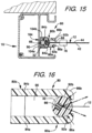
- FIG. 15 is a cross section of side column 16 taken along the line D-D in FIG. 1A .
- side column 16 and the accompanying guide track will be discussed herein, it should be understood that side column 18 is of similar construction, albeit with a housing and channel for the counterweight, and otherwise includes the same design elements and features as side column 16.
- side columns 16, 18 each include a guide track 80, 82 respectively, with each guide track being of identical construction.
- guide track 80 and the engagement of vertical edge 24 and drive tooth column 28 provided herein applies equally to guide track 82, vertical edge 26, and drive tooth column 30.
- Guide track 80 and drive teeth 32 may be configured to form a ball and socket like interface as seen in FIG. 16 .
- This configuration may be accomplished by providing drive teeth which have a curved outer surface, such as a spherical or cylindrical or rounded body and providing a guide tracks which have a first track 80a and a second track 80b which together form a c-shaped guide track.
- Each track 80a, 80b of guide track 80 may include a first portion 84a, 84b respectively, which extends laterally towards the doorway and a curved second portion 86a, 86b respectively, which extends from the first portion towards the opposing track.
- the curved second portions each stop short of each other, defining a gap 88 through which door panel 12 extends from doorway 15 into the guide track, with the combination of tracks 80a, 80b further defining a guide channel 90 in which the column of drive teeth 28 and vertical edge 24 travels as the door panel opens and closes.
- the interior portion of the curved second portion 86a, 86b of each track may include a curved seat 92a, 92b respectively which is configured to mate with the curvature of the drive teeth 32, forming a ball and socket like arrangement.
- any friction resulting from the drive teeth engaging the guide track may be substantially reduced as, for example, a wind load or pressure differential is applied to one or both sides of the door panel causing the door panel to bow in one direction and the drive teeth to engage the guide tracks to hold the door panel in place and not be blown out of the tracks.
- the drive teeth can freely rotate within the guide channel while engaged with the drive track in response to changes in the wind load or pressure differential on the door panel, as seen in FIG. 16 .
- the ball and socket configuration is particularly advantageous when opening or closing the door panel under a wind load or pressure differential as the configuration not only reduces friction on the drive teeth and side column, but also prevents the drive teeth from becoming jammed in the gap formed by the tracks as the door opens or closes under a wind load or pressure differential.
- the ball and socket configuration has the advantage over known systems, like for example the thickened bodies discussed herein, or laterally positioned cylindrical bodies which have the "top" flat edge engaging the guide tracks rather than a rounded middle portion, insofar as the rounded body can freely rotate in the matching side column and avoid edges or bodies which may become wedged within the gap in the side column, potentially jamming the door panel which increases friction and potentially damaging the door panel, wind lock, motor and/or guide track.
- a further advantage of using a ball and socket configuration is that the configuration helps prevent the drive teeth from disengaging from the vertical edges of the door panel under increased wind loads or pressure differentials, or in the event that the door panel is impacted and is required to break away from the guide tracks and side column.
- the inward catenary tension on the panel pulls the drive teeth towards gap 88 formed in guide track 80, and into engagement with the guide tracks.
- the reaction forces of the guide track and specifically second portion 86a, 86b of the tracks (as seen in FIG.
- drive teeth 32 pushes back on the exterior surface of drive teeth 32 in a way which causes the drive teeth to pinch down against door panel 12 and any longitudinal element 66 positioned in or coupled to the vertical edge 24 of the door panel.
- opening 58 and channel 60 of the drive tooth will clamp down on door panel 12 and/or Keder 68, enhancing the engagement between the teeth and the door panel and/or Keder to prevent teeth from breaking off or disengaging from the door panel.
- the clamping of the drive teeth helps maintain engagement of the drive teeth with the door panel, and reduces the size of the door panel and drive tooth columns, in order to make it easier for the door panel and drive tooth columns to pass through gap 88 and disengage from the side columns.
- the clamping of the drive teeth may also eliminate the need to fasten or fix each tooth to Keder or door panel insofar as the pinching will prevent the drive teeth from disengaging from the door panel when disengaging from the side column when an impact on the door panel occurs.
- Using a rounded shape for the drive teeth further helps maintain the engagement insofar as there are no edges or corners which can catch on the side columns and be pulled off the door panel.
- each guide track 80, 82 may include a discontinuity 94 for a disengaged vertical edge and associated drive tooth column to reenter the guide tracks proximate the top of the guide tracks as seen in FIG. 20
- the ball and socket configuration along with the continuous nature of each drive tooth column allows for the door panel and drive teeth to reenter the guide track at the point of disengagement from the track, i.e . where the door panel broke away from the guide track.
- the drive teeth and guide track of the present invention may provide for complete reinsertion without fully opening the door panel, only having to open the door panel to the height where the column of drive teeth and door panel exited the guide track.
- the flexible nature of the guide tracks and the ball and socket configuration allow for the guide teeth to simply pop back into the guide track where the lower most tooth remains engaged within the guide track after impact.
- discontinuity 94 is provided proximate the top of each track which allows for the door panel and drive tooth columns to be reinserted in the guide tracks as the door panel is moved to a full or substantially opened position.
- the guide tracks and guide track material may be altered to meet specific specifications of a particular environment. For example, where a lower wind load/pressure differential resistance but a higher disengageability is required, in an indoor setting with high traffic for example, the guide tracks may be made more flexible from top to bottom to allow for the drive tooth columns and door panel to more easily disengage from the guide tracks. Where a higher wind load/pressure differential resistance but a lower disengageability is required, in an outdoor loading dock setting for example, the guide tracks may be made less flexible and more rigid to better prevent the drive tooth columns and door panel from disengaging from the guide tracks.
- the door panel is better able to break away from the guide tracks throughout most of the opening/closing or winding/unwinding sequence if impacted by a break away force.
- the door panel can be better locked in place with a higher wind load or pressure differential resistance as the door panel approaches and reaches its final closed position, where the wind load or pressure differential load on the door panel becomes the highest as a result of a greater surface area of the door panel being exposed.
- the end of the closing sequence as the door approaches the fully closed position is also where the likelihood of an impact becomes the lowest, as the door panel is more visibly blocking the doorway, reducing the possibility of an accidental impact of the door panel.
- the configuration guide track 80 (and 82) may be changed in different portions of the guide track.
- gap 88 formed between the curved or second portions 86a, 86b of each track may be adjusted as desired.
- a majority of the guide track 100 (and above) may have a first gap width W, while a second smaller portion 102 proximate the bottom of the guide track, like for example the bottom 12-36 inches, has a reduced or narrower gap X.
- the reduced or narrower gap has the effect of keeping the drive tooth column engaged within the guide track by making it more difficult for the drive teeth and the drive tooth column to escape through the gap.
- tracks 80a, 80b may be made from UHMW plastic or polymers with track holders 104a, 104b being constructed from metal, steel, aluminum or the like.
- the track holders may only extend laterally across the first portion 84a, 84b of each track a very short distance, allowing a majority of each first portion of the flexible the tracks to flex easier so that the gap can be expanded and the door panel allowed to disengage therefrom.
- the track holder When extending only a short distance, the track holder provides some rigidity to the base of each track of the guide track, but primarily acts as a holder or anchor and mount to couple the guide track to the side column 16, 18.
- track holders 104a, 104b may extend laterally a first distance Y, while along a second smaller portion 108 (and below) proximate the bottom of each track 80a, 80b, like for example the bottom 12-36 inches of the guide track, track holder 104a, 104b may laterally across a second distance Z which is greater than the first distance Y.
- the door panel can be better locked in place with a higher wind load resistance as the door panel approaches and reaches its final closed position as the track holders will provide extra rigidity to the guide tracks where the wind load on the door panel becomes the highest as a result of a greater surface area of the door panel being exposed and the likelihood of an impact on the door panel becomes the lowest.
- guide or drive sprocket 110 is fixed to drum 17 and includes multiple sprocket teeth 114 separated by sprocket gaps 116 which mate with, and preferably match nearly identically or identically match, and are capable of engaging drive teeth 32.
- the respective drive sprockets By engaging and rotating with each column of drive teeth, the respective drive sprockets drive the drive tooth columns and door panel up and down as the door panel is opened and closed.
- Each sprocket may be made as a single body, or in a clamshell configuration wherein the sprocket is two separate bodies joined together as one.
- Clearances 128 provide room for the individual drive teeth 32 to deflect if any drive tooth slides along the attached vertical edge of the door panel or otherwise move out of synch or out of alignment with the mating sprocket teeth 114 and sprocket gaps 116. Rather than forcing the drive teeth into misalignment with the sprocket and sprocket teeth, potentially damaging the drive guide, one or more drive teeth, the door panel and/or the sprocket and any sprocket teeth, the clearance on each first and second portion of the drive channel allows for the drive tooth to transition into the clearance and slide into engagement with the next sprocket tooth and gap as the guide sprocket rotates. For example, as seen in FIG.
Landscapes
- Engineering & Computer Science (AREA)
- Structural Engineering (AREA)
- Architecture (AREA)
- Civil Engineering (AREA)
- Power-Operated Mechanisms For Wings (AREA)
- Wing Frames And Configurations (AREA)
Applications Claiming Priority (3)
| Application Number | Priority Date | Filing Date | Title |
|---|---|---|---|
| US201862773863P | 2018-11-30 | 2018-11-30 | |
| EP19890769.3A EP3887636B1 (fr) | 2018-11-30 | 2019-11-27 | Ensemble de porte avec deux pignons d'entraînement et deux guides d'entraînement correspondants |
| PCT/US2019/063700 WO2020113070A1 (fr) | 2018-11-30 | 2019-11-27 | Ensemble porte ayant un panneau de porte à fond souple et système et procédé d'entraînement de celui-ci |
Related Parent Applications (2)
| Application Number | Title | Priority Date | Filing Date |
|---|---|---|---|
| EP19890769.3A Division EP3887636B1 (fr) | 2018-11-30 | 2019-11-27 | Ensemble de porte avec deux pignons d'entraînement et deux guides d'entraînement correspondants |
| EP19890769.3A Division-Into EP3887636B1 (fr) | 2018-11-30 | 2019-11-27 | Ensemble de porte avec deux pignons d'entraînement et deux guides d'entraînement correspondants |
Publications (2)
| Publication Number | Publication Date |
|---|---|
| EP4582665A2 true EP4582665A2 (fr) | 2025-07-09 |
| EP4582665A3 EP4582665A3 (fr) | 2025-12-17 |
Family
ID=70849955
Family Applications (3)
| Application Number | Title | Priority Date | Filing Date |
|---|---|---|---|
| EP25178304.9A Pending EP4582665A3 (fr) | 2018-11-30 | 2019-11-27 | Ensemble porte ayant un panneau de porte à fond souple |
| EP19890769.3A Active EP3887636B1 (fr) | 2018-11-30 | 2019-11-27 | Ensemble de porte avec deux pignons d'entraînement et deux guides d'entraînement correspondants |
| EP25178301.5A Pending EP4582664A3 (fr) | 2018-11-30 | 2019-11-27 | Ensemble porte ayant un panneau de porte à fond souple |
Family Applications After (2)
| Application Number | Title | Priority Date | Filing Date |
|---|---|---|---|
| EP19890769.3A Active EP3887636B1 (fr) | 2018-11-30 | 2019-11-27 | Ensemble de porte avec deux pignons d'entraînement et deux guides d'entraînement correspondants |
| EP25178301.5A Pending EP4582664A3 (fr) | 2018-11-30 | 2019-11-27 | Ensemble porte ayant un panneau de porte à fond souple |
Country Status (5)
| Country | Link |
|---|---|
| US (6) | US12571254B2 (fr) |
| EP (3) | EP4582665A3 (fr) |
| CA (1) | CA3121198A1 (fr) |
| MX (5) | MX2021006256A (fr) |
| WO (1) | WO2020113070A1 (fr) |
Families Citing this family (10)
| Publication number | Priority date | Publication date | Assignee | Title |
|---|---|---|---|---|
| US10274216B2 (en) | 2008-08-22 | 2019-04-30 | Rite-Hite Holding Corporation | Under-floor pliable air duct/dispersion systems |
| WO2017123992A1 (fr) * | 2016-01-13 | 2017-07-20 | Ciw Enterprises, Inc. | Portes à enroulement et leur procédé de fixation |
| US11643864B2 (en) * | 2018-01-23 | 2023-05-09 | Pella Corporation | Screen edge retention and screen rethreading features for a hidden screen assembly and a fenestration assembly |
| WO2021050540A2 (fr) * | 2019-09-09 | 2021-03-18 | Rite-Hite Holding Corporation | Appareil et procédés de détection d'état de sortie de guide de rideau de porte |
| US12153989B2 (en) * | 2020-05-15 | 2024-11-26 | Rielec Automatización Industrial SL | High-speed tunnel for the reading and mass encoding of RFID labels contained in a package |
| WO2022015839A1 (fr) * | 2020-07-14 | 2022-01-20 | Rytec Corporation | Configuration de montants latéraux d'un ensemble formant porte |
| WO2022235891A1 (fr) * | 2021-05-07 | 2022-11-10 | Rite-Hite Holding Corporation | Procédés et appareil pour surveiller et/ou ajuster des manoeuvres de portes |
| EP4334566A1 (fr) * | 2021-05-07 | 2024-03-13 | Rite-Hite Holding Corporation | Procédés et appareil pour ajuster des manoeuvres de porte en réponse à des charges de pression superficielle |
| US12434083B2 (en) * | 2021-11-02 | 2025-10-07 | Smoke Guard, Inc. | Deployable fire or smoke barrier with manual egress |
| US12305446B2 (en) * | 2022-06-23 | 2025-05-20 | Dynatect Manufacturing, Inc. | Powered door system |
Citations (1)
| Publication number | Priority date | Publication date | Assignee | Title |
|---|---|---|---|---|
| US8607842B2 (en) | 2011-03-23 | 2013-12-17 | Rytec Corporation | Device and method for increasing the wind load resistance and disengage-ability of overhead roll-up doors |
Family Cites Families (157)
| Publication number | Priority date | Publication date | Assignee | Title |
|---|---|---|---|---|
| US528071A (en) | 1894-10-23 | Curtain | ||
| US2862399A (en) | 1958-12-02 | Prefabricated gear assembly | ||
| US436900A (en) | 1890-09-23 | Half to william o | ||
| US766541A (en) | 1903-10-12 | 1904-08-02 | Frederick Molledore Spiegle | Roller-screen. |
| US755675A (en) | 1903-10-12 | 1904-03-29 | Dayton Mfg Company | Curtain-fixture. |
| US1405618A (en) | 1920-01-02 | 1922-02-07 | Nels H Nelson | Rolling window screen |
| US1393405A (en) | 1920-10-14 | 1921-10-11 | Louis C Soteros | Screen |
| US1764880A (en) | 1925-06-08 | 1930-06-17 | Rolscreen Co | Guide track for rolling window screens |
| US1766730A (en) | 1928-03-17 | 1930-06-24 | Higgin Mfg Co | Drawbar for screens |
| US1749180A (en) | 1929-07-29 | 1930-03-04 | Rolscreen Co | Roll-screen latch |
| US1796760A (en) | 1929-12-11 | 1931-03-17 | Norquist Ralph August | Window screen |
| US1914431A (en) | 1930-04-01 | 1933-06-20 | Saul B Jacobs | Bottom rail for roller screens |
| US1832387A (en) | 1930-06-12 | 1931-11-17 | Hansen Bernard | Roller screen |
| US1866788A (en) | 1930-12-12 | 1932-07-12 | Arthur Metal Products Company | Roller screen |
| US1972182A (en) | 1931-12-05 | 1934-09-04 | Corry Metal Corp | Roll screen |
| US1925578A (en) | 1932-02-15 | 1933-09-05 | Higgin Mfg Co | Rolling light-tight closures |
| US1997846A (en) | 1933-01-30 | 1935-04-16 | Kinnear Mfg Co | Rolling door |
| US2126782A (en) | 1938-02-17 | 1938-08-16 | Chamberlin Metal Weather Strip | Roller screen |
| US2350288A (en) | 1943-09-04 | 1944-05-30 | Michelman Nathan | Guide rail for rolling doors |
| US2572334A (en) | 1948-08-12 | 1951-10-23 | Francis W Guibert | Gearing utilizing detachable gear teeth |
| US2803297A (en) | 1954-05-22 | 1957-08-20 | Wenke Helmuth Berthold Carlos | Roll shutters |
| US2797652A (en) | 1956-01-03 | 1957-07-02 | James S Waddell | Doughnut making machine |
| US3149665A (en) | 1962-01-19 | 1964-09-22 | Hunter Douglas Int Quebec Ltd | Roller type screens for windows |
| US3421568A (en) | 1966-06-29 | 1969-01-14 | Wilbur R Youngs | Flexible door closure |
| US3439551A (en) | 1967-09-13 | 1969-04-22 | Frank A Militana | Toothed wheel with replaceable toothed segments |
| US3430677A (en) | 1967-12-22 | 1969-03-04 | Ernest E Pierce | Roll-type closure |
| US3489200A (en) | 1968-03-22 | 1970-01-13 | Overhead Door Construction | Sealing and guiding structure for a door |
| US3864203A (en) | 1970-11-20 | 1975-02-04 | Owens Corning Fiberglass Corp | Fiber reinforced elastomers |
| US3796010A (en) | 1972-12-07 | 1974-03-12 | Presray Corp | Pneumatically sealable flood panel assembly |
| US3996814A (en) | 1974-09-13 | 1976-12-14 | Glen Edgar Westlake | Sprocket |
| US4016920A (en) | 1975-05-23 | 1977-04-12 | United States Steel Corporation | Flexible guiding track and release mechanism for an overhead rolling door assembly |
| US4222282A (en) | 1978-05-24 | 1980-09-16 | The Bendix Corporation | Rack and pinion teeth configuration |
| US4357978A (en) | 1980-06-02 | 1982-11-09 | Keller Products, Inc. | Roller shade seal system |
| US4478268B1 (en) | 1980-12-29 | 1991-04-23 | Door structure | |
| DK11881A (da) | 1981-01-13 | 1982-07-14 | P A Frederiksen | Gardin til lys og eller varmeafskaermning |
| GB2108839B (en) | 1981-10-13 | 1985-09-04 | Andrew Paul Cooper | Fire screens or curtains |
| GB2137271B (en) | 1983-03-18 | 1986-04-09 | Byrne & Davidson Ind Ltd | Windlocked rolling door |
| CA1221019A (fr) | 1983-06-10 | 1987-04-28 | H.M. Robert Labelle | Guide-galets pour fermeture roulante |
| IT1161493B (it) | 1983-07-11 | 1987-03-18 | Olivetti & Co Spa | Convertitore di corrente continua per alimentatori stabilizzati tipo switching |
| US4601320A (en) | 1984-02-09 | 1986-07-22 | Douglas Taylor | Industrial door |
| US4601321A (en) | 1984-05-10 | 1986-07-22 | Toyota Kidosha Kogyo Kabushiki Kaisha | Vertical die casting device |
| US4649981A (en) | 1985-03-07 | 1987-03-17 | Appropriate Technology Corporation | Edge seal for fabric covers |
| CA1260025A (fr) | 1985-11-14 | 1989-09-26 | M & I Door Systems Limited | Mecanisme de manoeuvre (ouverture et fermeture) d'une porte de complexe industriel |
| GB8624735D0 (en) | 1986-10-15 | 1986-11-19 | Clark Door Ltd | Roller door assemblies |
| BE906022A (fr) | 1986-12-23 | 1987-04-16 | Coenraets B J | Dispositif a volet. |
| US4887660A (en) | 1988-06-30 | 1989-12-19 | Frommelt Industries, Inc. | Roll-up door |
| US5365993A (en) | 1988-08-25 | 1994-11-22 | Jella John F | Sectional door |
| IT8904810V0 (it) | 1989-05-12 | 1989-05-12 | Sunproject Srl | Dispositivo per il bloccaggio in posizione di chiusura di un telo avvolgibile di protezione del vano di finestre e simili |
| US5219015A (en) | 1989-05-19 | 1993-06-15 | Nergeco Sa | Lifting curtain door |
| US5141043A (en) | 1989-05-19 | 1992-08-25 | Nergeco Sa | Lifting curtain door |
| EP0405093A3 (en) | 1989-06-27 | 1991-07-17 | Rytec Corporation | Apparatus configured for maintaining a barrier in a position against a trans-barrier force less than a predetermined magnitude |
| US5172744A (en) | 1989-10-23 | 1992-12-22 | Finch Harry E | Roll-up door system |
| US4987943A (en) | 1989-12-20 | 1991-01-29 | Cel-Franc Inc. | Wedging assembly for sealing an edge of a window shade |
| US5163495A (en) | 1990-06-08 | 1992-11-17 | Dale Lichy | Closure assembly for structural members |
| US5131450A (en) | 1990-06-08 | 1992-07-21 | Dale Lichy | Closure assembly for structural members |
| DE4029011A1 (de) | 1990-09-13 | 1992-03-19 | Webasto Ag Fahrzeugtechnik | Flexible kunststoff-zahnstange |
| CA2038862C (fr) | 1991-03-22 | 1995-10-24 | Douglas B. Taylor | Mecanisme compensateur pour porte a enroulement vertical a vitesse variable |
| US5139074A (en) | 1991-04-03 | 1992-08-18 | Kelley Company Inc. | Industrial door having flexible and releasable beam |
| US5123474A (en) * | 1991-05-13 | 1992-06-23 | Smith Richard C | Roll-up closure device |
| BE1004897A3 (fr) | 1991-05-24 | 1993-02-16 | Coenraets Benoit | Dispositif de fermeture, de separation ou de couverture. |
| DE4131762C2 (de) | 1991-09-24 | 1997-05-22 | Winkhaus Fa August | Betätigungsvorrichtung für einen Flügel eines Fensters, einer Tür, einer Lüftungsklappe oder dergleichen |
| FR2683259A1 (fr) | 1991-10-30 | 1993-05-07 | Nergeco Sa | Porte a rideau relevable a glissieres accessibles. |
| FR2689174A1 (fr) | 1992-03-27 | 1993-10-01 | Nergeco Sa | Dispositif d'équilibrage pour porte de manutention à rideau relevable. |
| US5392836A (en) | 1992-06-23 | 1995-02-28 | Rite Hite Corporation | Door assembly |
| US5222541A (en) | 1992-07-22 | 1993-06-29 | Kelley Company, Inc. | Industrial door having releasable beam and tension bracket retention mechanism |
| US5271448A (en) | 1992-07-27 | 1993-12-21 | Rytec Corporation | Movable barrier with two part guide follower |
| US5482104A (en) | 1993-06-04 | 1996-01-09 | Lichy; Dale M. | Guide system for vertically moveable flexible door |
| US5445209A (en) | 1993-06-04 | 1995-08-29 | Lichy; Dale M. | Guide system for vertically moveable flexible door |
| US5878803A (en) | 1993-09-08 | 1999-03-09 | Kraeutler; Bernard | Goods-handling door |
| US5450890A (en) | 1993-10-01 | 1995-09-19 | Rite-Hite Corporation | Roll-up strip curtain barrier apparatus |
| US5544690A (en) | 1994-05-11 | 1996-08-13 | Magro; Sebastian | Roll-up door provided with thermal protection means and a direct drive gearing arrangement |
| US6089305A (en) | 1995-02-10 | 2000-07-18 | Rite-Hite Holding Corporation | Curtain guiding assembly for a soft edge door with a selectively tensioned leading edge |
| US6357507B1 (en) | 1995-03-22 | 2002-03-19 | Räsontec N.V. Rabobank Trust Comp. Curacao N.V. | Curtain arrangement for preventing spread of smoke |
| US5632317A (en) | 1995-03-31 | 1997-05-27 | Overhead Door Corporation | Roll-up door |
| US5655591A (en) | 1995-03-31 | 1997-08-12 | Rite-Hite Corporation | Tension assembly for roller door |
| US5601133A (en) | 1995-03-31 | 1997-02-11 | Overhead Door Corporation | Roll-up door |
| US5722476A (en) | 1995-04-12 | 1998-03-03 | Ceraper S.L. | Reversible slatted shutter |
| US5657805A (en) | 1995-10-03 | 1997-08-19 | Magro; Sebastian | Wind-resistant overhead closure |
| US6019156A (en) * | 1996-05-09 | 2000-02-01 | Kelley Company, Inc. | Roll-up door |
| US6257303B1 (en) | 1996-11-08 | 2001-07-10 | Howick Engineering Limited | Rack and pinion door drive system |
| NZ330098A (en) | 1998-03-31 | 2000-09-29 | Howick Engineering Ltd | A rack and pinion door drive device for an automatic door with rack having bifurcate transverse section to locate onto rail of door track |
| DE19726156C2 (de) | 1997-06-20 | 2001-08-02 | Guido Langenbach | Schnellaufrolltor |
| CA2210283C (fr) | 1997-07-11 | 2003-01-07 | M & I Door Systems Limited | Porte-rideau avec bords a frottement reduit |
| BR9811549A (pt) | 1997-07-25 | 2000-11-28 | Rytec Corp | Porta suspensa de enrolar para aplicações sanitárias |
| US6039106A (en) | 1998-01-09 | 2000-03-21 | Albany International Corp. | Door with articulated cam |
| US5964271A (en) | 1998-05-01 | 1999-10-12 | Lapointe; Serge | Automatic screen structure |
| US6068040A (en) | 1998-07-24 | 2000-05-30 | Alpine Overhead Doors, Inc. | Slat edge retainer for overhead rolling doors |
| US6152208A (en) | 1998-10-13 | 2000-11-28 | Rytec Corporation | Flexible door with actuatable sealing mechanism |
| JP2000160961A (ja) * | 1998-11-24 | 2000-06-13 | Toyo Shutter Co Ltd | シートシャッター装置 |
| US6065525A (en) | 1999-02-04 | 2000-05-23 | Overhead Door Corporation | Rollup door assembly |
| US6341639B1 (en) | 2000-03-08 | 2002-01-29 | Wayne-Dalton Corporation | Apparatus and method for windlocking a building opening |
| US6431250B2 (en) | 2000-03-08 | 2002-08-13 | Wayne-Dalton Corporation | Apparatus and method for windlocking a building opening |
| US6296039B1 (en) | 2000-03-08 | 2001-10-02 | Wayne-Dalton Corporation | Apparatus and method for windlocking a building opening |
| US6574832B1 (en) | 2000-05-30 | 2003-06-10 | Rite-Hite Holding Corporation | Yieldable guide for a door |
| EP1191184A1 (fr) | 2000-09-25 | 2002-03-27 | Dynaco International | Dispositif à volet destiné à la fermeture d'une baie |
| US6394172B1 (en) | 2000-12-22 | 2002-05-28 | Jacques Kessous | Trackless roll-up door opening covering |
| KR200256886Y1 (ko) * | 2001-09-20 | 2001-12-31 | 정해국 | 도어 밀폐용 커튼 장치 |
| US6915832B2 (en) | 2001-10-25 | 2005-07-12 | Edward J. Stern, Jr. | Protection device for an overhead door |
| BE1014506A3 (fr) | 2001-12-03 | 2003-11-04 | Dynaco Internat | Dispositif a volet avec element de reintroduction. |
| BE1014712A3 (fr) | 2002-03-20 | 2004-03-02 | Dynaco Internat | Dispositif a volet presentant des bords lateraux flexibles |
| BE1014713A3 (fr) | 2002-03-20 | 2004-03-02 | Dynaco Internat | Dispositif a volet perfectionne. |
| US6792998B2 (en) | 2002-03-21 | 2004-09-21 | Kenneth David | Automatically resettable guide system for an overhead door |
| US6722416B2 (en) | 2002-04-03 | 2004-04-20 | Overhead Door Corporation | Flexible curtain rollup door with combination stiffening struts and windlocks |
| BE1016275A3 (fr) | 2002-06-13 | 2006-07-04 | Dynaco International Sa | Dipositif a volet enroulable autour d'un tambour. |
| KR20030095870A (ko) * | 2002-06-15 | 2003-12-24 | 주식회사 포스콘 | 가요성 시트 개폐장치 |
| US6959748B2 (en) | 2002-12-06 | 2005-11-01 | Wayne-Dalton Corp. | Apparatus for covering an opening in a building |
| GB0313587D0 (en) * | 2003-06-12 | 2003-07-16 | Cooper Andrew P | Barrier |
| CA2446648C (fr) | 2003-07-10 | 2005-03-29 | Tnr Industrial Doors Inc. | Porte-rideau flexible et guides connexes |
| CA2463208C (fr) * | 2003-07-10 | 2008-01-22 | Tnr Industrial Doors Inc. | Porte rideau souple et guides connexes |
| US6942003B2 (en) | 2003-07-25 | 2005-09-13 | Service Door Industries Limited | Roll-up door curtain and guides and bottom bar therefor |
| CN1580479B (zh) | 2003-08-12 | 2010-06-23 | 三和控股株式会社 | 薄板卷帘门装置 |
| US7028738B2 (en) | 2003-09-26 | 2006-04-18 | Ceccofiglio David H | Shutter system and barrier assembly for use in connection therewith |
| US20070131358A1 (en) | 2003-10-30 | 2007-06-14 | Shinya Iwasaki | Shutter curtain lifting prevention structure in shutter device |
| US7128125B2 (en) | 2004-03-09 | 2006-10-31 | Charles Harbison | Durable sealing curtain |
| BE1016320A3 (fr) | 2004-03-17 | 2006-08-01 | Dynaco International Sa | Dispositif a rideau deroulable. |
| US20050252623A1 (en) | 2004-05-12 | 2005-11-17 | Mctavish Donald | Flexible curtain closure device drive and containment mechanism |
| DE102005024657C5 (de) | 2004-11-19 | 2016-04-21 | Webasto Ag | Rolloanordnung für ein Fahrzeug |
| US20080093037A1 (en) | 2004-12-10 | 2008-04-24 | Bernard Kraeutler | Door Provided With a Curtain Which is Raisable by Winding and Has an Improved Lateral Tightness |
| BE1016495A3 (fr) * | 2005-04-15 | 2006-12-05 | Dynaco International Sa | |
| US7464743B1 (en) | 2005-10-24 | 2008-12-16 | Berger Jr Allen | Roll formed roll-up door guide with double wind bar end |
| US20070148429A1 (en) * | 2005-12-19 | 2007-06-28 | Mcgrath Ralph D | Tri-excluded WUCS glass fiber reinforced plastic composite articles and methods for making such articles |
| EP1840321A1 (fr) * | 2006-03-29 | 2007-10-03 | Dynaco International S.A. | Dispositif de fermeture avec un rideau présentant des bords latéraux flexibles |
| US7748431B2 (en) | 2006-06-05 | 2010-07-06 | Rite-Hite Holding Corporation | Track and guide system for a door |
| KR100698757B1 (ko) * | 2006-07-11 | 2007-03-21 | (주)우송티아이디 | 자동복구형 하이 스피드 도어장치 |
| WO2008016573A2 (fr) | 2006-07-29 | 2008-02-07 | Rytec Corporation | Ensemble de porte à haute vitesse |
| US9493948B1 (en) | 2006-09-15 | 2016-11-15 | Regents Of The University Of Minnesota | Self-supporting roof panel |
| JP4151725B2 (ja) * | 2006-10-30 | 2008-09-17 | 三和シヤッター工業株式会社 | シャッター装置 |
| WO2008127327A1 (fr) | 2006-12-27 | 2008-10-23 | Rytec Corporation | Ensemble de porte à vitesse élevée |
| EP1953018B1 (fr) | 2007-01-31 | 2010-03-17 | ArvinMeritor GmbH | Système de guidage pour un store à enrouleur d'un toit ouvrant |
| EP1956177A1 (fr) | 2007-02-07 | 2008-08-13 | Dynaco International S.A. | Dispositif à rideau flexible |
| EP1956178A1 (fr) | 2007-02-07 | 2008-08-13 | Dynaco International S.A. | Procédé de fabrication d'un volet et procédé de fabrication d'un ensemble de deux courroies crantées |
| EP1956176A1 (fr) | 2007-02-07 | 2008-08-13 | Dynaco International S.A. | Dispositif à rideau enroulable |
| EP2003284A1 (fr) * | 2007-06-13 | 2008-12-17 | Dynaco International S.A. | Dispositif à volet et élément de réintroduction d'un volet dans une glissière de guidage |
| US20090229767A1 (en) | 2008-03-12 | 2009-09-17 | Mullet Willis J | Storm curtain side retention system |
| US8935883B2 (en) | 2008-07-29 | 2015-01-20 | The Chamberlain Group, Inc. | Barrier operator with rack and pinion drive and coupling assembly for an integrated door and operator |
| GB0819360D0 (en) | 2008-10-22 | 2008-11-26 | Derolo Ltd | Roller cover |
| BRPI1005325A2 (pt) | 2009-01-28 | 2016-02-10 | Rytec Corp | método e dispositivo para prevenir a contaminação a partir de uma porta a qual abre verticalmente |
| US8113265B2 (en) | 2009-03-02 | 2012-02-14 | Rite-Hite Holding Corporation | Washdown door |
| JP5458695B2 (ja) | 2009-06-29 | 2014-04-02 | アイシン精機株式会社 | ロールシェード装置 |
| US8622112B2 (en) | 2009-09-15 | 2014-01-07 | Storm Solutions, Inc. | Retractable, low-profile storm shield systems and methods |
| US8291960B2 (en) | 2010-04-15 | 2012-10-23 | Tnr Industrial Doors Inc. | Pivoting bottom bar for roll-up door |
| US20120036955A1 (en) | 2010-08-10 | 2012-02-16 | Michael Gogola | Involute gear |
| IT1402346B1 (it) * | 2010-10-13 | 2013-08-30 | Ditec S P A | Dispositivo per il rilevamento della velocita' del telo di una porta ad avvolgimento rapido. |
| US9260911B2 (en) | 2011-03-23 | 2016-02-16 | Rytec Corporation | Door panel for overhead roll-up doors and a method for creating the same |
| US8851147B2 (en) | 2011-03-23 | 2014-10-07 | Rytec Corporation | Segmented wind lock configuration for overhead roll-up doors and method of constructing the same |
| US9187953B2 (en) | 2011-03-23 | 2015-11-17 | Rytec Corporation | Side column configuration for overhead roll-up door assemblies |
| TW201241297A (en) | 2011-04-06 | 2012-10-16 | Komatsu Denki Sangyo Kabushiki Kaisha | Sheet shutter |
| EP2757224B1 (fr) | 2011-06-24 | 2017-02-15 | Hayashiguchi Mfg Co., Ltd. | Dispositif d'écran à rouleaux |
| US8887790B2 (en) | 2011-09-13 | 2014-11-18 | Rytec Corporation | Wind lock configuration for overhead roll-up doors |
| US20130180673A1 (en) | 2012-01-18 | 2013-07-18 | Rami Hashimshony | High speed door mechanism |
| ES2434105B1 (es) * | 2012-05-11 | 2014-07-24 | Amiserru, S.L. | Puerta de apertura rápida |
| US9410363B2 (en) | 2012-06-25 | 2016-08-09 | Rite-Hite Holding Corporation | Insulated door panels |
| US9416589B2 (en) | 2012-12-11 | 2016-08-16 | Indotech Industrial Doors Inc. | Deformable guide for a rollable door, rollable door guiding system having a deformable guide, and door using the same |
| ES2555705B1 (es) | 2014-06-30 | 2016-10-14 | Llaza World, S.A. | Estor enrollable |
| ITUA20164156A1 (it) * | 2016-06-07 | 2017-12-07 | B Projet S R L | Telo di una porta avvolgibile, particolarmente a scorrimento rapido del tipo "autoriparabile". |
| US11028639B2 (en) * | 2016-06-10 | 2021-06-08 | Overhead Door Corporation | Low friction high speed roll door at high wind loads |
| US9702665B1 (en) * | 2016-08-01 | 2017-07-11 | Burose, LLC | Ballistic shade system |
-
2019
- 2019-11-27 EP EP25178304.9A patent/EP4582665A3/fr active Pending
- 2019-11-27 EP EP19890769.3A patent/EP3887636B1/fr active Active
- 2019-11-27 US US16/698,409 patent/US12571254B2/en active Active
- 2019-11-27 MX MX2021006256A patent/MX2021006256A/es unknown
- 2019-11-27 EP EP25178301.5A patent/EP4582664A3/fr active Pending
- 2019-11-27 WO PCT/US2019/063700 patent/WO2020113070A1/fr not_active Ceased
- 2019-11-27 CA CA3121198A patent/CA3121198A1/fr active Pending
-
2021
- 2021-05-27 MX MX2025005674A patent/MX2025005674A/es unknown
- 2021-05-27 MX MX2025005675A patent/MX2025005675A/es unknown
- 2021-05-27 MX MX2025005676A patent/MX2025005676A/es unknown
- 2021-05-27 MX MX2025005672A patent/MX2025005672A/es unknown
-
2024
- 2024-01-04 US US18/404,220 patent/US20240141726A1/en active Pending
- 2024-01-04 US US18/404,250 patent/US20240141727A1/en active Pending
- 2024-01-04 US US18/404,284 patent/US20240133239A1/en active Pending
- 2024-01-04 US US18/404,319 patent/US20240133241A1/en active Pending
- 2024-01-04 US US18/404,302 patent/US20240133240A1/en active Pending
Patent Citations (1)
| Publication number | Priority date | Publication date | Assignee | Title |
|---|---|---|---|---|
| US8607842B2 (en) | 2011-03-23 | 2013-12-17 | Rytec Corporation | Device and method for increasing the wind load resistance and disengage-ability of overhead roll-up doors |
Also Published As
| Publication number | Publication date |
|---|---|
| MX2025005672A (es) | 2025-06-02 |
| EP4582665A3 (fr) | 2025-12-17 |
| US20240133241A1 (en) | 2024-04-25 |
| EP3887636B1 (fr) | 2025-07-02 |
| EP4582664A2 (fr) | 2025-07-09 |
| MX2025005674A (es) | 2025-06-02 |
| MX2025005676A (es) | 2025-06-02 |
| US20240141727A1 (en) | 2024-05-02 |
| MX2021006256A (es) | 2021-09-10 |
| EP3887636A1 (fr) | 2021-10-06 |
| US20240133240A1 (en) | 2024-04-25 |
| US12571254B2 (en) | 2026-03-10 |
| EP3887636A4 (fr) | 2022-12-14 |
| CA3121198A1 (fr) | 2020-06-04 |
| US20200173231A1 (en) | 2020-06-04 |
| US20240141726A1 (en) | 2024-05-02 |
| EP4582664A3 (fr) | 2025-12-17 |
| WO2020113070A1 (fr) | 2020-06-04 |
| MX2025005675A (es) | 2025-06-02 |
| US20240133239A1 (en) | 2024-04-25 |
Similar Documents
| Publication | Publication Date | Title |
|---|---|---|
| US20240133241A1 (en) | Door assembly having a soft bottomed door panel and system and method of driving the same | |
| US7775252B2 (en) | Vertically movable door with safety barrier | |
| US5139074A (en) | Industrial door having flexible and releasable beam | |
| AU2010201885B2 (en) | High load operation of an industrial roll door | |
| US6481487B2 (en) | Guidance device for a flexible curtain door | |
| US11248416B2 (en) | Roll-up doors and method for securing same | |
| EP0808407B1 (fr) | Systeme pour tendre le bas d'un rideau | |
| US4852300A (en) | Stacking gates or doors | |
| US20200240205A1 (en) | Door assembly with flexible door having automatically locking bottom bar | |
| EP4182534B1 (fr) | Configuration de montants latéraux d'un ensemble formant porte | |
| US4754795A (en) | Shutter | |
| US20030041980A1 (en) | Cable tensioner for a door |
Legal Events
| Date | Code | Title | Description |
|---|---|---|---|
| PUAI | Public reference made under article 153(3) epc to a published international application that has entered the european phase |
Free format text: ORIGINAL CODE: 0009012 |
|
| STAA | Information on the status of an ep patent application or granted ep patent |
Free format text: STATUS: REQUEST FOR EXAMINATION WAS MADE |
|
| 17P | Request for examination filed |
Effective date: 20250522 |
|
| AC | Divisional application: reference to earlier application |
Ref document number: 3887636 Country of ref document: EP Kind code of ref document: P |
|
| AK | Designated contracting states |
Kind code of ref document: A2 Designated state(s): AL AT BE BG CH CY CZ DE DK EE ES FI FR GB GR HR HU IE IS IT LI LT LU LV MC MK MT NL NO PL PT RO RS SE SI SK SM TR |
|
| REG | Reference to a national code |
Ref country code: DE Ref legal event code: R079 Free format text: PREVIOUS MAIN CLASS: E06B0009580000 Ipc: E06B0009170000 |
|
| PUAL | Search report despatched |
Free format text: ORIGINAL CODE: 0009013 |
|
| AK | Designated contracting states |
Kind code of ref document: A3 Designated state(s): AL AT BE BG CH CY CZ DE DK EE ES FI FR GB GR HR HU IE IS IT LI LT LU LV MC MK MT NL NO PL PT RO RS SE SI SK SM TR |
|
| RIC1 | Information provided on ipc code assigned before grant |
Ipc: E06B 9/17 20060101AFI20250911BHEP Ipc: A47G 5/02 20060101ALI20250911BHEP Ipc: E06B 9/11 20060101ALI20250911BHEP Ipc: E06B 9/13 20060101ALI20250911BHEP Ipc: E06B 9/54 20060101ALI20250911BHEP Ipc: E06B 9/56 20060101ALI20250911BHEP Ipc: E06B 9/58 20060101ALI20250911BHEP |
|
| PUAF | Information related to the publication of a search report (a3 document) modified or deleted |
Free format text: ORIGINAL CODE: 0009199SEPU |
|
| PUAL | Search report despatched |
Free format text: ORIGINAL CODE: 0009013 |
|
| D17D | Deferred search report published (deleted) | ||
| AK | Designated contracting states |
Kind code of ref document: A3 Designated state(s): AL AT BE BG CH CY CZ DE DK EE ES FI FR GB GR HR HU IE IS IT LI LT LU LV MC MK MT NL NO PL PT RO RS SE SI SK SM TR |
|
| RIC1 | Information provided on ipc code assigned before grant |
Ipc: E06B 9/17 20060101AFI20251112BHEP Ipc: A47G 5/02 20060101ALI20251112BHEP Ipc: E06B 9/11 20060101ALI20251112BHEP Ipc: E06B 9/13 20060101ALI20251112BHEP Ipc: E06B 9/54 20060101ALI20251112BHEP Ipc: E06B 9/56 20060101ALI20251112BHEP Ipc: E06B 9/58 20060101ALI20251112BHEP |