EP4582678A1 - Procédé et dispositif de commande de rapport air-carburant pour moteur à combustion interne - Google Patents
Procédé et dispositif de commande de rapport air-carburant pour moteur à combustion interne Download PDFInfo
- Publication number
- EP4582678A1 EP4582678A1 EP22957434.8A EP22957434A EP4582678A1 EP 4582678 A1 EP4582678 A1 EP 4582678A1 EP 22957434 A EP22957434 A EP 22957434A EP 4582678 A1 EP4582678 A1 EP 4582678A1
- Authority
- EP
- European Patent Office
- Prior art keywords
- oxygen storage
- storage amount
- fuel ratio
- air
- purifying catalyst
- Prior art date
- Legal status (The legal status is an assumption and is not a legal conclusion. Google has not performed a legal analysis and makes no representation as to the accuracy of the status listed.)
- Granted
Links
Images


Classifications
-
- F—MECHANICAL ENGINEERING; LIGHTING; HEATING; WEAPONS; BLASTING
- F02—COMBUSTION ENGINES; HOT-GAS OR COMBUSTION-PRODUCT ENGINE PLANTS
- F02D—CONTROLLING COMBUSTION ENGINES
- F02D41/00—Electrical control of supply of combustible mixture or its constituents
- F02D41/02—Circuit arrangements for generating control signals
- F02D41/021—Introducing corrections for particular conditions exterior to the engine
- F02D41/0235—Introducing corrections for particular conditions exterior to the engine in relation with the state of the exhaust gas treating apparatus
- F02D41/0295—Control according to the amount of oxygen that is stored on the exhaust gas treating apparatus
-
- F—MECHANICAL ENGINEERING; LIGHTING; HEATING; WEAPONS; BLASTING
- F01—MACHINES OR ENGINES IN GENERAL; ENGINE PLANTS IN GENERAL; STEAM ENGINES
- F01N—GAS-FLOW SILENCERS OR EXHAUST APPARATUS FOR MACHINES OR ENGINES IN GENERAL; GAS-FLOW SILENCERS OR EXHAUST APPARATUS FOR INTERNAL-COMBUSTION ENGINES
- F01N3/00—Exhaust or silencing apparatus having means for purifying, rendering innocuous, or otherwise treating exhaust
- F01N3/08—Exhaust or silencing apparatus having means for purifying, rendering innocuous, or otherwise treating exhaust for rendering innocuous
- F01N3/10—Exhaust or silencing apparatus having means for purifying, rendering innocuous, or otherwise treating exhaust for rendering innocuous by thermal or catalytic conversion of noxious components of exhaust
- F01N3/101—Three-way catalysts
-
- F—MECHANICAL ENGINEERING; LIGHTING; HEATING; WEAPONS; BLASTING
- F01—MACHINES OR ENGINES IN GENERAL; ENGINE PLANTS IN GENERAL; STEAM ENGINES
- F01N—GAS-FLOW SILENCERS OR EXHAUST APPARATUS FOR MACHINES OR ENGINES IN GENERAL; GAS-FLOW SILENCERS OR EXHAUST APPARATUS FOR INTERNAL-COMBUSTION ENGINES
- F01N9/00—Electrical control of exhaust gas treating apparatus
-
- F—MECHANICAL ENGINEERING; LIGHTING; HEATING; WEAPONS; BLASTING
- F02—COMBUSTION ENGINES; HOT-GAS OR COMBUSTION-PRODUCT ENGINE PLANTS
- F02D—CONTROLLING COMBUSTION ENGINES
- F02D41/00—Electrical control of supply of combustible mixture or its constituents
- F02D41/02—Circuit arrangements for generating control signals
- F02D41/14—Introducing closed-loop corrections
- F02D41/1438—Introducing closed-loop corrections using means for determining characteristics of the combustion gases; Sensors therefor
- F02D41/1439—Introducing closed-loop corrections using means for determining characteristics of the combustion gases; Sensors therefor characterised by the position of the sensor
- F02D41/1441—Plural sensors
-
- F—MECHANICAL ENGINEERING; LIGHTING; HEATING; WEAPONS; BLASTING
- F02—COMBUSTION ENGINES; HOT-GAS OR COMBUSTION-PRODUCT ENGINE PLANTS
- F02D—CONTROLLING COMBUSTION ENGINES
- F02D41/00—Electrical control of supply of combustible mixture or its constituents
- F02D41/02—Circuit arrangements for generating control signals
- F02D41/14—Introducing closed-loop corrections
- F02D41/1438—Introducing closed-loop corrections using means for determining characteristics of the combustion gases; Sensors therefor
- F02D41/1444—Introducing closed-loop corrections using means for determining characteristics of the combustion gases; Sensors therefor characterised by the characteristics of the combustion gases
- F02D41/1454—Introducing closed-loop corrections using means for determining characteristics of the combustion gases; Sensors therefor characterised by the characteristics of the combustion gases the characteristics being an oxygen content or concentration or the air-fuel ratio
-
- F—MECHANICAL ENGINEERING; LIGHTING; HEATING; WEAPONS; BLASTING
- F02—COMBUSTION ENGINES; HOT-GAS OR COMBUSTION-PRODUCT ENGINE PLANTS
- F02D—CONTROLLING COMBUSTION ENGINES
- F02D41/00—Electrical control of supply of combustible mixture or its constituents
- F02D41/02—Circuit arrangements for generating control signals
- F02D41/14—Introducing closed-loop corrections
- F02D41/1438—Introducing closed-loop corrections using means for determining characteristics of the combustion gases; Sensors therefor
- F02D41/1473—Introducing closed-loop corrections using means for determining characteristics of the combustion gases; Sensors therefor characterised by the regulation method
- F02D41/1475—Regulating the air fuel ratio at a value other than stoichiometry
-
- F—MECHANICAL ENGINEERING; LIGHTING; HEATING; WEAPONS; BLASTING
- F01—MACHINES OR ENGINES IN GENERAL; ENGINE PLANTS IN GENERAL; STEAM ENGINES
- F01N—GAS-FLOW SILENCERS OR EXHAUST APPARATUS FOR MACHINES OR ENGINES IN GENERAL; GAS-FLOW SILENCERS OR EXHAUST APPARATUS FOR INTERNAL-COMBUSTION ENGINES
- F01N2430/00—Influencing exhaust purification, e.g. starting of catalytic reaction, filter regeneration, or the like, by controlling engine operating characteristics
- F01N2430/06—Influencing exhaust purification, e.g. starting of catalytic reaction, filter regeneration, or the like, by controlling engine operating characteristics by varying fuel-air ratio, e.g. by enriching fuel-air mixture
-
- F—MECHANICAL ENGINEERING; LIGHTING; HEATING; WEAPONS; BLASTING
- F01—MACHINES OR ENGINES IN GENERAL; ENGINE PLANTS IN GENERAL; STEAM ENGINES
- F01N—GAS-FLOW SILENCERS OR EXHAUST APPARATUS FOR MACHINES OR ENGINES IN GENERAL; GAS-FLOW SILENCERS OR EXHAUST APPARATUS FOR INTERNAL-COMBUSTION ENGINES
- F01N2560/00—Exhaust systems with means for detecting or measuring exhaust gas components or characteristics
- F01N2560/02—Exhaust systems with means for detecting or measuring exhaust gas components or characteristics the means being an exhaust gas sensor
- F01N2560/025—Exhaust systems with means for detecting or measuring exhaust gas components or characteristics the means being an exhaust gas sensor for measuring or detecting O2, e.g. lambda sensors
-
- F—MECHANICAL ENGINEERING; LIGHTING; HEATING; WEAPONS; BLASTING
- F01—MACHINES OR ENGINES IN GENERAL; ENGINE PLANTS IN GENERAL; STEAM ENGINES
- F01N—GAS-FLOW SILENCERS OR EXHAUST APPARATUS FOR MACHINES OR ENGINES IN GENERAL; GAS-FLOW SILENCERS OR EXHAUST APPARATUS FOR INTERNAL-COMBUSTION ENGINES
- F01N2560/00—Exhaust systems with means for detecting or measuring exhaust gas components or characteristics
- F01N2560/14—Exhaust systems with means for detecting or measuring exhaust gas components or characteristics having more than one sensor of one kind
-
- F—MECHANICAL ENGINEERING; LIGHTING; HEATING; WEAPONS; BLASTING
- F01—MACHINES OR ENGINES IN GENERAL; ENGINE PLANTS IN GENERAL; STEAM ENGINES
- F01N—GAS-FLOW SILENCERS OR EXHAUST APPARATUS FOR MACHINES OR ENGINES IN GENERAL; GAS-FLOW SILENCERS OR EXHAUST APPARATUS FOR INTERNAL-COMBUSTION ENGINES
- F01N2900/00—Details of electrical control or of the monitoring of the exhaust gas treating apparatus
- F01N2900/04—Methods of control or diagnosing
- F01N2900/0416—Methods of control or diagnosing using the state of a sensor, e.g. of an exhaust gas sensor
-
- F—MECHANICAL ENGINEERING; LIGHTING; HEATING; WEAPONS; BLASTING
- F01—MACHINES OR ENGINES IN GENERAL; ENGINE PLANTS IN GENERAL; STEAM ENGINES
- F01N—GAS-FLOW SILENCERS OR EXHAUST APPARATUS FOR MACHINES OR ENGINES IN GENERAL; GAS-FLOW SILENCERS OR EXHAUST APPARATUS FOR INTERNAL-COMBUSTION ENGINES
- F01N2900/00—Details of electrical control or of the monitoring of the exhaust gas treating apparatus
- F01N2900/06—Parameters used for exhaust control or diagnosing
- F01N2900/16—Parameters used for exhaust control or diagnosing said parameters being related to the exhaust apparatus, e.g. particulate filter or catalyst
- F01N2900/1624—Catalyst oxygen storage capacity
-
- F—MECHANICAL ENGINEERING; LIGHTING; HEATING; WEAPONS; BLASTING
- F02—COMBUSTION ENGINES; HOT-GAS OR COMBUSTION-PRODUCT ENGINE PLANTS
- F02D—CONTROLLING COMBUSTION ENGINES
- F02D2200/00—Input parameters for engine control
- F02D2200/02—Input parameters for engine control the parameters being related to the engine
- F02D2200/08—Exhaust gas treatment apparatus parameters
- F02D2200/0814—Oxygen storage amount
Definitions
- a three-way catalyst as an exhaust purifying catalyst is capable of oxidizing CO and HC and reducing NOx in the exhaust gas, in order to achieve a high level of both oxidation and reduction by catalytic action, it is important for the catalyst to be able to absorb, store and release oxygen, the so-called oxygen storage amount. Therefore, a technique has been known to estimate the amount of oxygen storage in the three-way catalyst and control a target air-fuel ratio to maintain this oxygen storage amount within an appropriate range.
- Patent Document 1 Japanese Patent Application Publication No. 2015-71959
- the target oxygen storage amount is set not at the median of the first oxygen storage amount and second oxygen storage amount, but at the side with smaller oxygen storage amount, namely, closer to the first oxygen storage amount.
- the difference in oxygen storage amount from the target oxygen storage amount to the first oxygen storage amount is larger than the difference in oxygen storage amount from the target oxygen storage amount to the second oxygen storage amount. Therefore, when there is an estimation error due to disturbance or some other factor, the frequency at which the estimated oxygen storage amount is reset when the actual oxygen storage amount reaches the second oxygen storage amount is relatively less, as compared with the frequency at which the estimated oxygen storage amount is reset when the actual oxygen storage amount reaches the first oxygen storage amount. Consequently, NOx emissions, which have the characteristic of increasing rapidly when the oxygen storage amount becomes equal to or larger than the second oxygen storage amount, are suppressed.
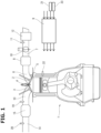
- FIG. 1 is an illustrative view showing the schematic configuration of an internal combustion engine 1 in one embodiment to which the present invention is applied.
- Internal combustion engine 1 in one embodiment is a four-stroke cycle spark-ignition internal combustion engine (so-called gasoline engine), and is equipped with an intake valve 2, an exhaust valve 3 and a spark plug 4 in each cylinder.
- it is configured as a cylinder direct-injection engine, and a fuel injection valve 5 which injects fuel into a cylinder is disposed, for example, on the intake valve 2 side.
- internal combustion engine 1 may have a port injection type configuration in which fuel is injected toward an intake port 6.
- Three-way catalyst 15 is, for example, a so-called monolithic ceramic catalyst in which a catalyst layer containing a catalyst metal is coated on the surface of a monolithic ceramic body in which fine passages are formed.
- Three-way catalyst 15 may further include a downstream-side catalyst arranged in series (so-called under-floor catalyst).
- the estimated oxygen storage amount deviates from an actual oxygen storage amount due to some disturbance or estimation error, the actual oxygen storage amount of three-way catalyst 15 becomes smaller or larger than the target oxygen storage amount, and the air-fuel ratio of the exhaust gas flowing out of three-way catalyst 15, that is, the exhaust air-fuel ratio detected by downstream-side air-fuel ratio sensor 20 (hereafter, this is referred to as "downstream-side exhaust air-fuel ratio") changes to the rich side or the lean side. Based on these changes in the downstream-side exhaust air-fuel ratio, the estimated oxygen storage amount is reset to be in accordance with the actual oxygen storage amount.
- a first oxygen storage amount OSA1, where the oxygen storage amount is smaller than the target oxygen storage amount, and a second oxygen storage amount OSA2, where the oxygen storage amount is larger than the target oxygen storage amount, are preset, and threshold values RAF1 and RAF2 for the downstream-side exhaust air-fuel ratio are given for first and second oxygen storage amounts OSA1 and OSA2, respectively.
- Threshold value RAF1 is set on the slightly richer side than the air-fuel ratio equivalent to the theoretical air-fuel ratio
- threshold value RAF2 is set on the slightly leaner side than the air-fuel ratio equivalent to the theoretical air-fuel ratio.
- FIG. 3 is a flowchart showing the air-fuel ratio control based on the oxygen storage amount.
- the oxygen storage amount of three-way catalyst 15 is estimated based on the upstream-side exhaust air-fuel ratio (FrA/F) detected by upstream-side air-fuel ratio sensor 19 and the intake air amount detected by air flow meter 11, which corresponds to the gas flow rate flowing into three-way catalyst 15.
- the "intake air amount” does not mean the amount of air per cylinder cycle, but rather the flow rate of air per unit time that is sucked into internal combustion engine 1 (that is, passes through air flow meter 11).
- step 6 based on the estimated oxygen storage amount and a predetermined target oxygen storage amount, a required target air-fuel ratio is calculated such that the estimated oxygen storage amount matches the target oxygen storage amount.
- FIG. 4 is a block diagram showing the process of step 6, and the difference between the estimated oxygen storage amount and the target oxygen storage amount is obtained in a target air-fuel ratio calculation section 31, and a target air-fuel ratio is calculated such that the oxygen storage amount changes at an appropriate rate. For example, when the estimated oxygen storage amount is larger than the target oxygen storage amount, the target air-fuel ratio is set richer than the theoretical air-fuel ratio. Conversely, when the estimated oxygen storage amount is smaller than the target oxygen storage amount, the target air-fuel ratio is set leaner than the theoretical air-fuel ratio.
- the target oxygen storage amount is not the median of first oxygen storage amount OSA1 and second oxygen storage amount OSA2, but is set within the range where the oxygen storage amount is smaller than the median.
- the oxygen storage amount can be treated in terms of the mass of oxygen (unit "g"), conventionally, it can be expressed as a percentage of the maximum oxygen storage amount of three-way catalyst 15, which is 100 (%).
- first oxygen storage amount OSA1 is larger than 10% of the maximum oxygen storage amount of three-way catalyst 15, and second oxygen storage amount OSA2 is smaller than 90% of the maximum oxygen storage amount of three-way catalyst 15.
- the target oxygen storage amount is smaller than 40% of the maximum oxygen storage amount of three-way catalyst 15.
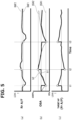
- FIG. 2 is a characteristic diagram schematically showing the relationship between the oxygen storage amount of three-way catalyst 15 and CO and NOx flowing out of three-way catalyst 15. As illustrated, both CO emissions and NOx emissions are minimized when the oxygen storage amount of three-way catalyst 15 is within a certain intermediate range. When the oxygen storage amount becomes smaller than a certain level, CO flows out of three-way catalyst 15. The emission amount of this CO increases proportionally with the decrease in oxygen storage amount. The same trend applies to HC that needs to be oxidized.
- NOx stars to flow out of three-way catalyst 15 when the oxygen storage amount becomes greater than a certain level, and the emission amount of this NOx has the characteristic of increasing rapidly when the oxygen storage amount exceeds a certain level. Then, as oxygen storage amount approaches 100%, the gradient of NOx increase becomes slower.
- three-way catalyst 15 is illustrated as an exhaust purifying catalyst, the present invention can be similarly applied to exhaust purifying catalysts having oxygen storage capacity other than three-way catalysts.
Landscapes
- Engineering & Computer Science (AREA)
- Chemical & Material Sciences (AREA)
- Combustion & Propulsion (AREA)
- Mechanical Engineering (AREA)
- General Engineering & Computer Science (AREA)
- Materials Engineering (AREA)
- Health & Medical Sciences (AREA)
- Chemical Kinetics & Catalysis (AREA)
- Toxicology (AREA)
- Electrical Control Of Air Or Fuel Supplied To Internal-Combustion Engine (AREA)
- Exhaust Gas After Treatment (AREA)
Applications Claiming Priority (1)
| Application Number | Priority Date | Filing Date | Title |
|---|---|---|---|
| PCT/JP2022/032936 WO2024047839A1 (fr) | 2022-09-01 | 2022-09-01 | Procédé et dispositif de commande de rapport air-carburant pour moteur à combustion interne |
Publications (3)
| Publication Number | Publication Date |
|---|---|
| EP4582678A1 true EP4582678A1 (fr) | 2025-07-09 |
| EP4582678A4 EP4582678A4 (fr) | 2025-10-29 |
| EP4582678B1 EP4582678B1 (fr) | 2026-03-18 |
Family
ID=90098995
Family Applications (1)
| Application Number | Title | Priority Date | Filing Date |
|---|---|---|---|
| EP22957434.8A Active EP4582678B1 (fr) | 2022-09-01 | 2022-09-01 | Procédé et dispositif de commande de rapport air-carburant pour moteur à combustion interne |
Country Status (5)
| Country | Link |
|---|---|
| US (1) | US20260071584A1 (fr) |
| EP (1) | EP4582678B1 (fr) |
| JP (1) | JP7758210B2 (fr) |
| CN (1) | CN119731414A (fr) |
| WO (1) | WO2024047839A1 (fr) |
Family Cites Families (10)
| Publication number | Priority date | Publication date | Assignee | Title |
|---|---|---|---|---|
| US5678402A (en) * | 1994-03-23 | 1997-10-21 | Honda Giken Kogyo Kabushiki Kaisha | Air-fuel ratio control system for internal combustion engines and exhaust system temperature-estimating device applicable thereto |
| JP3572961B2 (ja) * | 1998-10-16 | 2004-10-06 | 日産自動車株式会社 | エンジンの排気浄化装置 |
| JP3622661B2 (ja) * | 2000-10-06 | 2005-02-23 | トヨタ自動車株式会社 | 内燃機関の空燃比制御装置 |
| JP3729083B2 (ja) * | 2001-04-27 | 2005-12-21 | 日産自動車株式会社 | エンジンの排気浄化装置 |
| US7918086B2 (en) * | 2005-10-19 | 2011-04-05 | Ford Global Technologies, Llc | System and method for determining a NOx storage capacity of catalytic device |
| JP5326969B2 (ja) * | 2009-09-28 | 2013-10-30 | トヨタ自動車株式会社 | 内燃機関の燃料供給量制御装置 |
| JP5360312B1 (ja) * | 2013-01-29 | 2013-12-04 | トヨタ自動車株式会社 | 内燃機関の制御装置 |
| JP6094438B2 (ja) * | 2013-09-27 | 2017-03-15 | トヨタ自動車株式会社 | 内燃機関の制御装置 |
| JP6056726B2 (ja) | 2013-10-02 | 2017-01-11 | トヨタ自動車株式会社 | 内燃機関の制御装置 |
| JP7047742B2 (ja) | 2018-12-12 | 2022-04-05 | 株式会社デンソー | 状態推定装置 |
-
2022
- 2022-09-01 WO PCT/JP2022/032936 patent/WO2024047839A1/fr not_active Ceased
- 2022-09-01 CN CN202280099165.1A patent/CN119731414A/zh active Pending
- 2022-09-01 US US19/107,554 patent/US20260071584A1/en active Pending
- 2022-09-01 EP EP22957434.8A patent/EP4582678B1/fr active Active
- 2022-09-01 JP JP2024543728A patent/JP7758210B2/ja active Active
Also Published As
| Publication number | Publication date |
|---|---|
| EP4582678A4 (fr) | 2025-10-29 |
| JP7758210B2 (ja) | 2025-10-22 |
| US20260071584A1 (en) | 2026-03-12 |
| WO2024047839A1 (fr) | 2024-03-07 |
| JPWO2024047839A1 (fr) | 2024-03-07 |
| EP4582678B1 (fr) | 2026-03-18 |
| CN119731414A (zh) | 2025-03-28 |
Similar Documents
| Publication | Publication Date | Title |
|---|---|---|
| US8892337B2 (en) | Apparatus for detecting imbalance abnormality in air-fuel ratio between cylinders in multi-cylinder internal combustion engine | |
| EP0926327B1 (fr) | Régulateur de combustion et méthode pour moteur à combustion de mélange pauvre | |
| EP1477652A2 (fr) | Système de contrôle des émissions d'un moteur à combustion interne | |
| WO2012157059A1 (fr) | Dispositif de commande de rapport air/carburant pour moteur à combustion interne | |
| JP3988518B2 (ja) | 内燃機関の排ガス浄化装置 | |
| WO2005017336A1 (fr) | Dispositif de commande de moteur a combustion interne | |
| JP6711310B2 (ja) | 内燃機関の排気処理装置 | |
| EP4582678B1 (fr) | Procédé et dispositif de commande de rapport air-carburant pour moteur à combustion interne | |
| US8122705B2 (en) | Exhaust cleaning apparatus and method thereof | |
| US12529330B2 (en) | Control method and control device for internal combustion engine | |
| US20140331973A1 (en) | Internal combustion engine | |
| JP7718589B2 (ja) | 三元触媒の酸素ストレージ量制御方法および装置 | |
| JP3309776B2 (ja) | 内燃機関の点火時期制御装置 | |
| JP4389139B2 (ja) | 内燃機関の排出ガス浄化制御装置 | |
| JP2004346917A (ja) | 内燃機関制御装置 | |
| JP4468287B2 (ja) | 内燃機関の排ガス浄化装置 | |
| JP3834951B2 (ja) | 内燃機関の空燃比制御装置 | |
| JPH11107828A (ja) | 内燃機関の空燃比制御装置 | |
| JP2010112192A (ja) | 内燃機関の排気浄化装置 | |
| WO2025163844A1 (fr) | Procédé et dispositif de commande de rapport air-carburant pour moteur à combustion interne | |
| JP5074717B2 (ja) | 内燃機関の燃料噴射制御装置 | |
| KR20180067898A (ko) | 엔진의 소기 제어 시의 배기 가스 저감 방법 | |
| JP5040838B2 (ja) | 内燃機関の制御装置 | |
| JP2005155331A (ja) | ディーゼルエンジンの燃料噴射制御装置 | |
| JPH0429855B2 (fr) |
Legal Events
| Date | Code | Title | Description |
|---|---|---|---|
| STAA | Information on the status of an ep patent application or granted ep patent |
Free format text: STATUS: THE INTERNATIONAL PUBLICATION HAS BEEN MADE |
|
| PUAI | Public reference made under article 153(3) epc to a published international application that has entered the european phase |
Free format text: ORIGINAL CODE: 0009012 |
|
| STAA | Information on the status of an ep patent application or granted ep patent |
Free format text: STATUS: REQUEST FOR EXAMINATION WAS MADE |
|
| 17P | Request for examination filed |
Effective date: 20250306 |
|
| AK | Designated contracting states |
Kind code of ref document: A1 Designated state(s): AL AT BE BG CH CY CZ DE DK EE ES FI FR GB GR HR HU IE IS IT LI LT LU LV MC MK MT NL NO PL PT RO RS SE SI SK SM TR |
|
| REG | Reference to a national code |
Ref country code: DE Ref legal event code: R079 Free format text: PREVIOUS MAIN CLASS: F01N0003200000 Ipc: F02D0041020000 Ref country code: DE Ref legal event code: R079 Ref document number: 602022032790 Country of ref document: DE Free format text: PREVIOUS MAIN CLASS: F01N0003200000 Ipc: F02D0041020000 |
|
| A4 | Supplementary search report drawn up and despatched |
Effective date: 20250929 |
|
| RIC1 | Information provided on ipc code assigned before grant |
Ipc: F02D 41/02 20060101AFI20250923BHEP Ipc: F02D 41/14 20060101ALI20250923BHEP Ipc: F01N 3/20 20060101ALI20250923BHEP Ipc: F01N 3/22 20060101ALI20250923BHEP Ipc: F02D 45/00 20060101ALI20250923BHEP |
|
| DAV | Request for validation of the european patent (deleted) | ||
| DAX | Request for extension of the european patent (deleted) | ||
| GRAP | Despatch of communication of intention to grant a patent |
Free format text: ORIGINAL CODE: EPIDOSNIGR1 |
|
| STAA | Information on the status of an ep patent application or granted ep patent |
Free format text: STATUS: GRANT OF PATENT IS INTENDED |
|
| RIC1 | Information provided on ipc code assigned before grant |
Ipc: F02D 41/02 20060101AFI20251219BHEP Ipc: F02D 41/14 20060101ALI20251219BHEP Ipc: F01N 3/20 20060101ALI20251219BHEP Ipc: F01N 3/22 20060101ALI20251219BHEP Ipc: F02D 45/00 20060101ALI20251219BHEP Ipc: F01N 3/10 20060101ALI20251219BHEP Ipc: F01N 9/00 20060101ALI20251219BHEP |
|
| GRAS | Grant fee paid |
Free format text: ORIGINAL CODE: EPIDOSNIGR3 |
|
| GRAA | (expected) grant |
Free format text: ORIGINAL CODE: 0009210 |
|
| STAA | Information on the status of an ep patent application or granted ep patent |
Free format text: STATUS: THE PATENT HAS BEEN GRANTED |
|
| INTG | Intention to grant announced |
Effective date: 20260120 |
|
| AK | Designated contracting states |
Kind code of ref document: B1 Designated state(s): AL AT BE BG CH CY CZ DE DK EE ES FI FR GB GR HR HU IE IS IT LI LT LU LV MC MK MT NL NO PL PT RO RS SE SI SK SM TR |
|
| REG | Reference to a national code |
Ref country code: CH Ref legal event code: F10 Free format text: ST27 STATUS EVENT CODE: U-0-0-F10-F00 (AS PROVIDED BY THE NATIONAL OFFICE) Effective date: 20260318 Ref country code: GB Ref legal event code: FG4D |
|
| REG | Reference to a national code |
Ref country code: IE Ref legal event code: FG4D |
|
| REG | Reference to a national code |
Ref country code: DE Ref legal event code: R096 Ref document number: 602022032790 Country of ref document: DE |