EP4582830A1 - Drahtfedersensorverschluss - Google Patents
Drahtfedersensorverschluss Download PDFInfo
- Publication number
- EP4582830A1 EP4582830A1 EP24150753.2A EP24150753A EP4582830A1 EP 4582830 A1 EP4582830 A1 EP 4582830A1 EP 24150753 A EP24150753 A EP 24150753A EP 4582830 A1 EP4582830 A1 EP 4582830A1
- Authority
- EP
- European Patent Office
- Prior art keywords
- closure device
- wire spring
- housing portion
- housing
- retaining
- Prior art date
- Legal status (The legal status is an assumption and is not a legal conclusion. Google has not performed a legal analysis and makes no representation as to the accuracy of the status listed.)
- Pending
Links
Images


Classifications
-
- G—PHYSICS
- G01—MEASURING; TESTING
- G01S—RADIO DIRECTION-FINDING; RADIO NAVIGATION; DETERMINING DISTANCE OR VELOCITY BY USE OF RADIO WAVES; LOCATING OR PRESENCE-DETECTING BY USE OF THE REFLECTION OR RERADIATION OF RADIO WAVES; ANALOGOUS ARRANGEMENTS USING OTHER WAVES
- G01S7/00—Details of systems according to groups G01S13/00, G01S15/00, G01S17/00
- G01S7/02—Details of systems according to groups G01S13/00, G01S15/00, G01S17/00 of systems according to group G01S13/00
- G01S7/027—Constructional details of housings, e.g. form, type, material or ruggedness
-
- B—PERFORMING OPERATIONS; TRANSPORTING
- B60—VEHICLES IN GENERAL
- B60W—CONJOINT CONTROL OF VEHICLE SUB-UNITS OF DIFFERENT TYPE OR DIFFERENT FUNCTION; CONTROL SYSTEMS SPECIALLY ADAPTED FOR HYBRID VEHICLES; ROAD VEHICLE DRIVE CONTROL SYSTEMS FOR PURPOSES NOT RELATED TO THE CONTROL OF A PARTICULAR SUB-UNIT
- B60W60/00—Drive control systems specially adapted for autonomous road vehicles
- B60W60/001—Planning or execution of driving tasks
- B60W60/0027—Planning or execution of driving tasks using trajectory prediction for other traffic participants
-
- G—PHYSICS
- G01—MEASURING; TESTING
- G01D—MEASURING NOT SPECIALLY ADAPTED FOR A SPECIFIC VARIABLE; ARRANGEMENTS FOR MEASURING TWO OR MORE VARIABLES NOT COVERED IN A SINGLE OTHER SUBCLASS; TARIFF METERING APPARATUS; MEASURING OR TESTING NOT OTHERWISE PROVIDED FOR
- G01D11/00—Component parts of measuring arrangements not specially adapted for a specific variable
- G01D11/16—Elements for restraining, or preventing the movement of, parts, e.g. for zeroising
- G01D11/18—Springs
-
- G—PHYSICS
- G01—MEASURING; TESTING
- G01D—MEASURING NOT SPECIALLY ADAPTED FOR A SPECIFIC VARIABLE; ARRANGEMENTS FOR MEASURING TWO OR MORE VARIABLES NOT COVERED IN A SINGLE OTHER SUBCLASS; TARIFF METERING APPARATUS; MEASURING OR TESTING NOT OTHERWISE PROVIDED FOR
- G01D11/00—Component parts of measuring arrangements not specially adapted for a specific variable
- G01D11/24—Housings ; Casings for instruments
- G01D11/245—Housings for sensors
-
- G—PHYSICS
- G01—MEASURING; TESTING
- G01S—RADIO DIRECTION-FINDING; RADIO NAVIGATION; DETERMINING DISTANCE OR VELOCITY BY USE OF RADIO WAVES; LOCATING OR PRESENCE-DETECTING BY USE OF THE REFLECTION OR RERADIATION OF RADIO WAVES; ANALOGOUS ARRANGEMENTS USING OTHER WAVES
- G01S13/00—Systems using the reflection or reradiation of radio waves, e.g. radar systems; Analogous systems using reflection or reradiation of waves whose nature or wavelength is irrelevant or unspecified
- G01S13/88—Radar or analogous systems specially adapted for specific applications
- G01S13/93—Radar or analogous systems specially adapted for specific applications for anti-collision purposes
- G01S13/931—Radar or analogous systems specially adapted for specific applications for anti-collision purposes of land vehicles
-
- H—ELECTRICITY
- H05—ELECTRIC TECHNIQUES NOT OTHERWISE PROVIDED FOR
- H05K—PRINTED CIRCUITS; CASINGS OR CONSTRUCTIONAL DETAILS OF ELECTRIC APPARATUS; MANUFACTURE OF ASSEMBLAGES OF ELECTRICAL COMPONENTS
- H05K5/00—Casings, cabinets or drawers for electric apparatus
- H05K5/10—Casings, cabinets or drawers for electric apparatus comprising several parts forming a closed casing
- H05K5/15—Casings, cabinets or drawers for electric apparatus comprising several parts forming a closed casing assembled by resilient members
-
- H—ELECTRICITY
- H05—ELECTRIC TECHNIQUES NOT OTHERWISE PROVIDED FOR
- H05K—PRINTED CIRCUITS; CASINGS OR CONSTRUCTIONAL DETAILS OF ELECTRIC APPARATUS; MANUFACTURE OF ASSEMBLAGES OF ELECTRICAL COMPONENTS
- H05K7/00—Constructional details common to different types of electric apparatus
- H05K7/20—Modifications to facilitate cooling, ventilating, or heating
- H05K7/2039—Modifications to facilitate cooling, ventilating, or heating characterised by the heat transfer by conduction from the heat generating element to a dissipating body
- H05K7/20409—Outer radiating structures on heat dissipating housings, e.g. fins integrated with the housing
-
- B—PERFORMING OPERATIONS; TRANSPORTING
- B60—VEHICLES IN GENERAL
- B60W—CONJOINT CONTROL OF VEHICLE SUB-UNITS OF DIFFERENT TYPE OR DIFFERENT FUNCTION; CONTROL SYSTEMS SPECIALLY ADAPTED FOR HYBRID VEHICLES; ROAD VEHICLE DRIVE CONTROL SYSTEMS FOR PURPOSES NOT RELATED TO THE CONTROL OF A PARTICULAR SUB-UNIT
- B60W2420/00—Indexing codes relating to the type of sensors based on the principle of their operation
- B60W2420/40—Photo, light or radio wave sensitive means, e.g. infrared sensors
- B60W2420/408—Radar; Laser, e.g. lidar
-
- G—PHYSICS
- G01—MEASURING; TESTING
- G01S—RADIO DIRECTION-FINDING; RADIO NAVIGATION; DETERMINING DISTANCE OR VELOCITY BY USE OF RADIO WAVES; LOCATING OR PRESENCE-DETECTING BY USE OF THE REFLECTION OR RERADIATION OF RADIO WAVES; ANALOGOUS ARRANGEMENTS USING OTHER WAVES
- G01S13/00—Systems using the reflection or reradiation of radio waves, e.g. radar systems; Analogous systems using reflection or reradiation of waves whose nature or wavelength is irrelevant or unspecified
- G01S13/88—Radar or analogous systems specially adapted for specific applications
- G01S13/93—Radar or analogous systems specially adapted for specific applications for anti-collision purposes
- G01S13/931—Radar or analogous systems specially adapted for specific applications for anti-collision purposes of land vehicles
- G01S2013/9323—Alternative operation using light waves
-
- G—PHYSICS
- G01—MEASURING; TESTING
- G01S—RADIO DIRECTION-FINDING; RADIO NAVIGATION; DETERMINING DISTANCE OR VELOCITY BY USE OF RADIO WAVES; LOCATING OR PRESENCE-DETECTING BY USE OF THE REFLECTION OR RERADIATION OF RADIO WAVES; ANALOGOUS ARRANGEMENTS USING OTHER WAVES
- G01S13/00—Systems using the reflection or reradiation of radio waves, e.g. radar systems; Analogous systems using reflection or reradiation of waves whose nature or wavelength is irrelevant or unspecified
- G01S13/88—Radar or analogous systems specially adapted for specific applications
- G01S13/93—Radar or analogous systems specially adapted for specific applications for anti-collision purposes
- G01S13/931—Radar or analogous systems specially adapted for specific applications for anti-collision purposes of land vehicles
- G01S2013/9324—Alternative operation using ultrasonic waves
-
- G—PHYSICS
- G01—MEASURING; TESTING
- G01S—RADIO DIRECTION-FINDING; RADIO NAVIGATION; DETERMINING DISTANCE OR VELOCITY BY USE OF RADIO WAVES; LOCATING OR PRESENCE-DETECTING BY USE OF THE REFLECTION OR RERADIATION OF RADIO WAVES; ANALOGOUS ARRANGEMENTS USING OTHER WAVES
- G01S7/00—Details of systems according to groups G01S13/00, G01S15/00, G01S17/00
- G01S7/48—Details of systems according to groups G01S13/00, G01S15/00, G01S17/00 of systems according to group G01S17/00
- G01S7/481—Constructional features, e.g. arrangements of optical elements
- G01S7/4811—Constructional features, e.g. arrangements of optical elements common to transmitter and receiver
- G01S7/4813—Housing arrangements
Definitions
- Radar sensors are conventionally used in connection with detecting and classifying objects in an environment. Radar is particularly robust with regard to lighting and weather conditions. Often, radar sensors are deployed with cameras and/or lidar sensors to provide different modes of detection and redundancy. In certain scenarios, performance of lidar and/or cameras can be supplemented by radar when affected by environmental features, such as temperature, fog, rain, snow, bright sunlight, lack of adequate light, etc.
- Autonomous vehicles often have to operate in extreme temperatures and other extreme conditions.
- Sensor systems e.g., radar sensors, camera sensors, lidar sensors, sonar sensors, etc.
- sensor housings need to be able to tolerate large temperature ranges, including extremely low temperatures that can cause the sensor housing to contract and extremely high temperatures that can cause the sensor housing to expand. Contraction and expansion of the sensor housing can deteriorate the effectiveness of fasteners used to hold the sensor housing together. This problem can be exacerbated when the fasteners used to hold the sensor housing together are of a different material than the housing itself, and therefore have different expansion and contraction properties.
- the housing is a sensor housing for housing a sensor (e.g., radar, lidar, camera, sonar, etc.) employed in autonomous vehicles, aircrafts, watercrafts, and the like.
- a sensor e.g., radar, lidar, camera, sonar, etc.
- a first housing portion may be formed of a first plastic and another may be formed of a metal or another plastic that is denser than the first plastic.
- a screw used to fasten the two housing portions together may provide a secure coupling when the housing portions are originally secured, but the coupling can become compromised over time due to the different thermal tolerances of the different materials used for the two housing portions.
- the plastic portion may expand and contract much more during temperature changes than the metal portion.
- a mechanical fastener such as a metal screw may not contract as much as the plastic material, causing a loose fit at low temperatures.
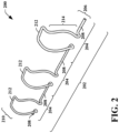
- the wire spring closure device comprises an upper portion coupled to a spring portion which in turn is coupled to a lower portion.
- the upper portion comprises an upper retaining bar
- the lower portion comprises a lower retaining bar.
- the lower portion mates with receiving slots in a retaining structure on a lower housing portion such that the lower retaining bar is positioned against a lower surface of the retaining structure on the lower housing portion.
- the upper portion of the wire spring closure device is engaged with the upper housing portion by forcing the upper retaining bar along a sloped mating feature on the upper housing portion until the upper retaining bar drops into retaining notches in the upper housing portion. As the upper retaining bar traverses the sloped mating feature, the spring portion of the wire spring closure device is stretched.
- the spring portion of the wire spring closure device is locked in a stretched or extended state and biases the upper housing portion against the lower housing portion to securely and removably lock the upper and lower portions together.
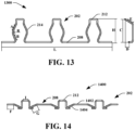
- the upper housing portion comprises a heat sink with cooling fins.
- One or more of the cooling fins is modified to have a sloped edge along which the upper retaining bar is forced during engagement, and a retaining notch into which the upper retaining bar drops after traversing the sloped edge.
- the described housing portions and wire spring closure device form a sensor housing system that can be deployed on an autonomous vehicle.
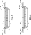
- Fig. 5 shows a side view 500 the upper housing portion 302 and the lower housing portion 304 prior to engagement of the wire spring closure device 202 by the closure tools 310.
- Operation of the closure tools 310 can be automated or can be performed manually. In another embodiment, application of the wire spring closure device can be performed manually without the closure tool(s).
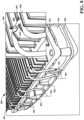
- Fig. 9 is a top-down view 900 of the upper housing portion 302. Shown in this view are the cooling fins 402 and the upper portions 210 of the wire spring closure device 202 in their locked positions on the fins 402. Also shown is the retaining structure 308 of the lower housing portion 304. Reinforcement brackets 802 are visible on the retaining structure 308.
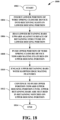
- Fig. 18 illustrates an exemplary methodology relating to securing two or more sensor housing portions together using a wire spring closure device in accordance with various aspects described herein. While the methodology is shown and described as being a series of acts that are performed in a sequence, it is to be understood and appreciated that the methodology is not limited by the order of the sequence. For example, some acts can occur in a different order than is described herein. In addition, an act can occur concurrently with another act. Further, in some instances, not all acts may be required to implement a methodology described herein.
- the method begins at 1802.
- a lower portion of a wire spring closure device is inserted into receiving slots in a lower housing portion to be secured to an upper housing portion.
- the receiving slots are disposed in a retaining structure on the lower housing portion.
- lower retaining bars on the lower portion of the wire spring closure device are biased upward against the lower surface of the retaining structure on the lower housing portion.
- an upper portion of the wire spring closure device is pushed toward mating features on the upper housing portion.
- the spring tension generated by stretching the spring portions of the wire spring closure device causes the upper retaining bars to exert a downward force on the upper housing portion and the lower retaining bars to exert an upward force on the lower housing portion, thereby securing the upward housing portion to the lower housing portion in a lockable and unlockable manner.
- the method terminates at 1814.
- Fig. 19 shows a manual removal tool 1900
- the removal process can be automated, such as in a case where multiple sensor housings need to be opened in order to service their contents.
- the described wire spring closure device may be employed to secure any desired type of housing or container and is not limited to a sensor housing.
- the wire spring closure device may be employed to close other containers such as shipping containers, storage containers, food containers, or any other container for which a secure, airtight, watertight, etc. closure is desired.
- a sensor housing system includes a first housing portion, a second housing portion, and a wire spring closure device having a closure feature configured to secure the first housing portion to the second housing portion.
- the wire spring closure device includes a first portion comprising a first retaining bar and a spring portion coupled to the first portion.
- the wire spring closure device further includes a second portion coupled to the spring portion and comprising a second retaining bar.
- the second retaining bar abuts a surface of the retaining structure.
- the first housing portion includes retaining notches that retain the first retaining bar when in an engaged position.
- the first housing portion includes a sloped feature that directs the first retaining bar into the retaining notches during engagement of the closure feature.
- the spring portion when stretched in an engaged position, biases the first retaining bar toward the first housing portion and biases the second retaining bar toward the retaining structure to secure the first housing portion to the second housing portion.
- the first housing portion includes a heat sink including cooling fins.
- the cooling fins include retaining notches that retain the first retaining bar when in an engaged position.
- the cooling fins include a sloped feature that directs the first retaining bar into the retaining notches during engagement of the closure feature.
Landscapes
- Engineering & Computer Science (AREA)
- Physics & Mathematics (AREA)
- Remote Sensing (AREA)
- Radar, Positioning & Navigation (AREA)
- General Physics & Mathematics (AREA)
- Computer Networks & Wireless Communication (AREA)
- Microelectronics & Electronic Packaging (AREA)
- Electromagnetism (AREA)
- Thermal Sciences (AREA)
- Automation & Control Theory (AREA)
- Human Computer Interaction (AREA)
- Transportation (AREA)
- Mechanical Engineering (AREA)
- Casings For Electric Apparatus (AREA)
Priority Applications (2)
| Application Number | Priority Date | Filing Date | Title |
|---|---|---|---|
| EP24150753.2A EP4582830A1 (de) | 2024-01-08 | 2024-01-08 | Drahtfedersensorverschluss |
| US18/414,395 US20250224483A1 (en) | 2024-01-08 | 2024-01-16 | Wire spring sensor closure |
Applications Claiming Priority (1)
| Application Number | Priority Date | Filing Date | Title |
|---|---|---|---|
| EP24150753.2A EP4582830A1 (de) | 2024-01-08 | 2024-01-08 | Drahtfedersensorverschluss |
Publications (1)
| Publication Number | Publication Date |
|---|---|
| EP4582830A1 true EP4582830A1 (de) | 2025-07-09 |
Family
ID=89535881
Family Applications (1)
| Application Number | Title | Priority Date | Filing Date |
|---|---|---|---|
| EP24150753.2A Pending EP4582830A1 (de) | 2024-01-08 | 2024-01-08 | Drahtfedersensorverschluss |
Country Status (2)
| Country | Link |
|---|---|
| US (1) | US20250224483A1 (de) |
| EP (1) | EP4582830A1 (de) |
Citations (8)
| Publication number | Priority date | Publication date | Assignee | Title |
|---|---|---|---|---|
| GB483742A (en) * | 1936-10-27 | 1938-04-26 | Keith Alexander Robinson | Improvements in closures for bottles, jars and like containers |
| US20040001315A1 (en) * | 2002-06-28 | 2004-01-01 | Yue-June Li | Heat dissipation assembly |
| DE102007042173A1 (de) * | 2007-09-05 | 2009-03-12 | Hella Kgaa Hueck & Co. | Radarsensor |
| US20100014224A1 (en) * | 2006-07-19 | 2010-01-21 | Continental Automotive Gmbh | Housing for Receiving an Electronic Assembly |
| US20130081361A1 (en) * | 2009-06-08 | 2013-04-04 | 3Rd Stone Design Inc. | Food container |
| US20130334268A1 (en) * | 2012-06-13 | 2013-12-19 | Decoma (Germany) Gmbh | Carrier device |
| DE202017103974U1 (de) * | 2017-07-04 | 2017-12-11 | Gl-Design Gmbh | Klammer aus Federstahldraht |
| EP4140822A1 (de) * | 2021-08-25 | 2023-03-01 | Bayerische Motoren Werke Aktiengesellschaft | Befestigungsvorrichtung für einen umfeldsensor sowie sensorverbausystem für ein fahrzeug |
Family Cites Families (3)
| Publication number | Priority date | Publication date | Assignee | Title |
|---|---|---|---|---|
| US7746647B2 (en) * | 2007-12-18 | 2010-06-29 | Fu Zhun Precision Industry (Shen Zhen) Co., Ltd. | Clip and heat dissipation assembly using the same |
| EP2348561A1 (de) * | 2010-01-23 | 2011-07-27 | Braun GmbH | Batteriekontaktfeder |
| DE102016123439A1 (de) * | 2016-12-05 | 2018-06-07 | Valeo Schalter Und Sensoren Gmbh | Radarsensor für ein Fahrzeug und Verfahren zum Zusammenbau eines Radarsensors |
-
2024
- 2024-01-08 EP EP24150753.2A patent/EP4582830A1/de active Pending
- 2024-01-16 US US18/414,395 patent/US20250224483A1/en active Pending
Patent Citations (8)
| Publication number | Priority date | Publication date | Assignee | Title |
|---|---|---|---|---|
| GB483742A (en) * | 1936-10-27 | 1938-04-26 | Keith Alexander Robinson | Improvements in closures for bottles, jars and like containers |
| US20040001315A1 (en) * | 2002-06-28 | 2004-01-01 | Yue-June Li | Heat dissipation assembly |
| US20100014224A1 (en) * | 2006-07-19 | 2010-01-21 | Continental Automotive Gmbh | Housing for Receiving an Electronic Assembly |
| DE102007042173A1 (de) * | 2007-09-05 | 2009-03-12 | Hella Kgaa Hueck & Co. | Radarsensor |
| US20130081361A1 (en) * | 2009-06-08 | 2013-04-04 | 3Rd Stone Design Inc. | Food container |
| US20130334268A1 (en) * | 2012-06-13 | 2013-12-19 | Decoma (Germany) Gmbh | Carrier device |
| DE202017103974U1 (de) * | 2017-07-04 | 2017-12-11 | Gl-Design Gmbh | Klammer aus Federstahldraht |
| EP4140822A1 (de) * | 2021-08-25 | 2023-03-01 | Bayerische Motoren Werke Aktiengesellschaft | Befestigungsvorrichtung für einen umfeldsensor sowie sensorverbausystem für ein fahrzeug |
Also Published As
| Publication number | Publication date |
|---|---|
| US20250224483A1 (en) | 2025-07-10 |
Similar Documents
| Publication | Publication Date | Title |
|---|---|---|
| JP4033772B2 (ja) | 車体構造素子を自動車の構造体に固定するクリップ | |
| US8585121B2 (en) | Device for fastening a vehicle interior trim panel | |
| US11867219B2 (en) | Rail mounting apparatus, system and method of securing devices to a structure | |
| US20160091011A1 (en) | Apparatus, system, and method for retaining a nut element to a part | |
| US10006479B2 (en) | Fastener clip assembly with funnel guide | |
| US7954206B2 (en) | Pin and grommet fastener assembly | |
| EP3300197B1 (de) | Selbstindizierende mutternplatte | |
| US10302109B2 (en) | Panel fastening system | |
| US9314904B2 (en) | Method for attaching a photovoltaic panel | |
| EP4582830A1 (de) | Drahtfedersensorverschluss | |
| US10914337B2 (en) | Fastener locating and retention design to accommodate part expansion and contraction | |
| CN112081807A (zh) | 紧固件 | |
| US20250226792A1 (en) | Torque Tube Clamps for Automated Solar Panel Installation | |
| CN1083334A (zh) | 防松扣件 | |
| US20180026577A1 (en) | Device for attaching a solar panel | |
| US7523980B2 (en) | Mounting structure and mounting method for resin vehicle panel | |
| US6257794B1 (en) | Sliding mount for securing a plastics motor vehicle body part piece on a support | |
| US5508902A (en) | Methods and apparatus for the interlocking of parts by a tab-and-slot arrangement | |
| US6347491B1 (en) | Separable fastener system, a method of assembly, and an assembly assembled thereby | |
| US20070046054A1 (en) | Interior trim accessory attachment apparatus | |
| US6942280B2 (en) | System for attaching colored insert to vehicle frame assembly | |
| US11542975B2 (en) | Blind assembly fastener system | |
| US5446957A (en) | Apparatus and method for forming a vehicle panel having a preplugged | |
| US20080141500A1 (en) | Retainer-plastic trim molding | |
| US11821451B2 (en) | Blind assembly fastener system |
Legal Events
| Date | Code | Title | Description |
|---|---|---|---|
| PUAI | Public reference made under article 153(3) epc to a published international application that has entered the european phase |
Free format text: ORIGINAL CODE: 0009012 |
|
| STAA | Information on the status of an ep patent application or granted ep patent |
Free format text: STATUS: THE APPLICATION HAS BEEN PUBLISHED |
|
| AK | Designated contracting states |
Kind code of ref document: A1 Designated state(s): AL AT BE BG CH CY CZ DE DK EE ES FI FR GB GR HR HU IE IS IT LI LT LU LV MC ME MK MT NL NO PL PT RO RS SE SI SK SM TR |
|
| STAA | Information on the status of an ep patent application or granted ep patent |
Free format text: STATUS: REQUEST FOR EXAMINATION WAS MADE |
|
| 17P | Request for examination filed |
Effective date: 20251209 |