EP4582834A1 - Laserradar - Google Patents
Laserradar Download PDFInfo
- Publication number
- EP4582834A1 EP4582834A1 EP23858563.2A EP23858563A EP4582834A1 EP 4582834 A1 EP4582834 A1 EP 4582834A1 EP 23858563 A EP23858563 A EP 23858563A EP 4582834 A1 EP4582834 A1 EP 4582834A1
- Authority
- EP
- European Patent Office
- Prior art keywords
- module
- lidar
- laser beam
- height
- optomechanics
- Prior art date
- Legal status (The legal status is an assumption and is not a legal conclusion. Google has not performed a legal analysis and makes no representation as to the accuracy of the status listed.)
- Pending
Links
Images






Classifications
-
- G—PHYSICS
- G01—MEASURING; TESTING
- G01S—RADIO DIRECTION-FINDING; RADIO NAVIGATION; DETERMINING DISTANCE OR VELOCITY BY USE OF RADIO WAVES; LOCATING OR PRESENCE-DETECTING BY USE OF THE REFLECTION OR RERADIATION OF RADIO WAVES; ANALOGOUS ARRANGEMENTS USING OTHER WAVES
- G01S7/00—Details of systems according to groups G01S13/00, G01S15/00, G01S17/00
- G01S7/48—Details of systems according to groups G01S13/00, G01S15/00, G01S17/00 of systems according to group G01S17/00
- G01S7/481—Constructional features, e.g. arrangements of optical elements
- G01S7/4816—Constructional features, e.g. arrangements of optical elements of receivers alone
-
- G—PHYSICS
- G01—MEASURING; TESTING
- G01S—RADIO DIRECTION-FINDING; RADIO NAVIGATION; DETERMINING DISTANCE OR VELOCITY BY USE OF RADIO WAVES; LOCATING OR PRESENCE-DETECTING BY USE OF THE REFLECTION OR RERADIATION OF RADIO WAVES; ANALOGOUS ARRANGEMENTS USING OTHER WAVES
- G01S17/00—Systems using the reflection or reradiation of electromagnetic waves other than radio waves, e.g. lidar systems
- G01S17/88—Lidar systems specially adapted for specific applications
- G01S17/93—Lidar systems specially adapted for specific applications for anti-collision purposes
- G01S17/931—Lidar systems specially adapted for specific applications for anti-collision purposes of land vehicles
-
- G—PHYSICS
- G01—MEASURING; TESTING
- G01S—RADIO DIRECTION-FINDING; RADIO NAVIGATION; DETERMINING DISTANCE OR VELOCITY BY USE OF RADIO WAVES; LOCATING OR PRESENCE-DETECTING BY USE OF THE REFLECTION OR RERADIATION OF RADIO WAVES; ANALOGOUS ARRANGEMENTS USING OTHER WAVES
- G01S7/00—Details of systems according to groups G01S13/00, G01S15/00, G01S17/00
- G01S7/48—Details of systems according to groups G01S13/00, G01S15/00, G01S17/00 of systems according to group G01S17/00
- G01S7/481—Constructional features, e.g. arrangements of optical elements
-
- G—PHYSICS
- G01—MEASURING; TESTING
- G01S—RADIO DIRECTION-FINDING; RADIO NAVIGATION; DETERMINING DISTANCE OR VELOCITY BY USE OF RADIO WAVES; LOCATING OR PRESENCE-DETECTING BY USE OF THE REFLECTION OR RERADIATION OF RADIO WAVES; ANALOGOUS ARRANGEMENTS USING OTHER WAVES
- G01S7/00—Details of systems according to groups G01S13/00, G01S15/00, G01S17/00
- G01S7/48—Details of systems according to groups G01S13/00, G01S15/00, G01S17/00 of systems according to group G01S17/00
- G01S7/481—Constructional features, e.g. arrangements of optical elements
- G01S7/4811—Constructional features, e.g. arrangements of optical elements common to transmitter and receiver
- G01S7/4813—Housing arrangements
-
- G—PHYSICS
- G01—MEASURING; TESTING
- G01S—RADIO DIRECTION-FINDING; RADIO NAVIGATION; DETERMINING DISTANCE OR VELOCITY BY USE OF RADIO WAVES; LOCATING OR PRESENCE-DETECTING BY USE OF THE REFLECTION OR RERADIATION OF RADIO WAVES; ANALOGOUS ARRANGEMENTS USING OTHER WAVES
- G01S7/00—Details of systems according to groups G01S13/00, G01S15/00, G01S17/00
- G01S7/48—Details of systems according to groups G01S13/00, G01S15/00, G01S17/00 of systems according to group G01S17/00
- G01S7/481—Constructional features, e.g. arrangements of optical elements
- G01S7/4817—Constructional features, e.g. arrangements of optical elements relating to scanning
Definitions
- This disclosure relates to the field of environmental perception and, in particular, to a LiDAR.
- the LiDAR is an important sensor for perceiving surrounding information. With the gradual development of forward-sensing LiDARs, it has become increasingly important in the field of mass-produced vehicles to better mount a LiDAR onto a vehicle body (even the inner side of a windshield.).
- a region near a rearview mirror on the inner side of the windshield of the vehicle body is typically occupied by devices such as a main camera, the heights of these devices are low, and the existing LiDAR is higher than these devices, so that the requirement for arrangement of the existing LiDAR in the region near the rearview mirror on the inner side of the windshield of the vehicle body is not met.
- an external vehicle body e.g., a front vehicle roof
- the height of the existing LiDAR hardly meets the actual design requirements of the vehicle body, and it is difficult for the LiDAR to strike a balance between small size and performance parameters.
- this disclosure provides a LiDAR to reduce the height of the LiDAR, so that the LiDAR is miniaturized in structure, the assembly and production of the LiDAR are facilitated, the requirements for a mounting environment in a vehicle body can be met, and easy compatibility and integration with the vehicle body are achieved.
- LiDAR including:
- the emitter module and the receiver module are arranged on two sides of the optomechanics module, respectively.
- the emitter module, the receiver module, and the scanner module are arranged within the preset height of the optomechanics module.
- the scanner module includes:
- a ratio of a height of the scanner module to a height of the LiDAR is greater than or equal to 0.72.
- a ratio of a height of the first scanner module to a height of the LiDAR is greater than or equal to 0.72.
- the first scanner module includes:
- the magnetic component and the first scanning mirror are arranged on two sides of the fixing component, respectively.
- the second scanner module is configured to scan and direct a first scanned laser beam formed by the first scanner module to the outside of the LiDAR, and scan and direct the echo laser beam onto the first scanner module.
- a ratio of a height of the second scanner module to a height of the LiDAR is greater than or equal to 0.8.
- the second scanner module includes:
- an angle between an optical axis of the laser beam directed onto a first scanning mirror of the first scanner module and the first scanning mirror at an initial position ranges from 50° to 60°.
- an angle between an optical axis of a first scanned laser beam formed by the first scanner module at an initial position and a second scanning mirror of the second scanner module at an initial position ranges from 30° to 40°, and an optical axis of a second scanned laser beam formed by reflecting the first scanned laser beam by the second scanning mirror at the initial position is perpendicular to a window of the LiDAR.
- the first scanning mirror reciprocates at an angle ranging from 4° to 8° in the second direction, and is configured to scan the laser beam directed onto the first scanning mirror in the first direction.
- the second scanning mirror reciprocates at an angle ranging from 15° to 30° in the first direction, and is configured to scan the laser beam directed onto the second scanning mirror in the second direction.
- a scanning direction of the first scanner module is a fast-axis direction of the scanner module when scanning
- a scanning direction of the second scanner module is a slow-axis direction of the scanner module when scanning
- the emitter module and the receiver module are arranged on two sides of the optomechanics module, respectively.
- the emitter module and the receiver module are obliquely and symmetrically arranged on two sides of the optomechanics module, respectively.
- the optics device includes: a receiving deflecting mirror configured to reflect the received echo laser beam through the optomechanics module and vertically direct the echo laser beam onto the receiver module.
- the optics device further includes: a light homogenizing component arranged close to one end of the emitter module and configured to change a shape of a light spot formed by the detection laser beam.
- the optics device further includes: an emitting deflecting mirror arranged adjacent to the emitter module along a height direction of the LiDAR and configured to reflect the detection laser beam through the optomechanics module and vertically direct the detection laser beam onto the optics device of the optomechanics module.
- an emitting deflecting mirror arranged adjacent to the emitter module along a height direction of the LiDAR and configured to reflect the detection laser beam through the optomechanics module and vertically direct the detection laser beam onto the optics device of the optomechanics module.
- the optics device further includes:
- the light homogenizing component includes a cylindrical lens array.
- the cylindrical lens array includes a plurality of cylindrical lens units arranged in sequence along a height direction of the LiDAR and configured to change the shape of the light spot formed by the detection laser beam.
- the optomechanics module includes a lens barrel and a mounter unit.
- the optics device further includes:
- the mounter unit and the lens barrel are arranged in the optomechanics module or a lens barrel structure of optical components, and the lens barrel structure of optical components is detachably mounted on the optomechanics module.
- the mounter unit and the lens barrel are located on a same surface of the optomechanics module.
- the mounter unit is arranged in the optomechanics module, and the lens barrel is detachably mounted in the optomechanics module.
- the lens barrel structure of optical components is integrally formed with an emitter module fixing portion of the LiDAR, and the emitter module fixing portion is configured to fixedly mount the emitter module.
- the lens barrel structure of optical components is integrally formed with an emitter module fixing portion of the LiDAR and a receiver module fixing portion of the LiDAR, and the receiver module fixing portion is configured to fixedly mount the receiver module.
- a LiDAR provided in embodiments of this disclosure includes: an emitter module configured to emit a detection laser beam; a receiver module configured to receive an echo laser beam of the detection laser beam reflected by a target object; a scanner module configured to scan the detection laser beam and the echo laser beam; and an optomechanics module having a preset height and configured to mount an optics device of the LiDAR.
- the emitter module and the receiver module are arranged on two sides of the optomechanics module, respectively.
- the emitter module, the receiver module, and the scanner module are arranged within the preset height of the optomechanics module.
- the first scanner module includes: the first scanning mirror; and the first driver device, where the ratio of the height of the first scanning mirror to the height of the first driver device is 1.
- the main structures (the first scanning mirror and the first driver device) forming the first scanner module are set to have the same height.
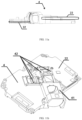
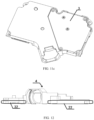
- FIG. 13 shows a schematic diagram of an arrangement position of a mounter unit and a lens barrel of a LiDAR, provided in embodiments of this disclosure
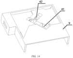
- Fig. 14 shows a schematic diagram of another arrangement position of a mounter unit and a lens barrel of a LiDAR, provided in embodiments of this disclosure
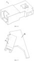
- Fig. 15a shows a schematic structural diagram of a partial structure of a LiDAR, provided in embodiments of this disclosure
- Fig. 15b shows a perspective view of a lens barrel of the LiDAR in Fig. 15a
- Fig. 15c shows a schematic structural diagram of an optomechanics module of the LiDAR in Fig. 15a
- Fig. 15d shows a bottom view of the LiDAR in Fig. 15a
- Fig. 15a shows a schematic structural diagram of an arrangement position of a mounter unit and a lens barrel of a LiDAR, provided in embodiments of this disclosure
- Fig. 14 shows a schematic diagram of another arrangement position of a mounter
- a LiDAR provided in embodiments of this disclosure includes:
- the laser 21 can be an edge emitting laser ("EEL”) or a vertical-cavity surface-emitting laser (“VCSEL”).).
- EEL edge emitting laser
- VCSEL vertical-cavity surface-emitting laser
- the detection laser beams emitted from the multiple groups of lasers 21 in a time-dividing manner are detected by corresponding detector groups in a time-dividing manner, respectively, to reduce the mutual interference between the detector groups and increase the coverage rate of detection.
- the multiple lasers 21 can also emit the detection laser beams simultaneously, and the lasers 21 can no longer be grouped.
- a control circuit board 8 (shown in Fig. 2 ) where the lasers 21 are located employs single-sided component arrangement, that is, electronic components are arranged on one surface of the control circuit board, and copper is exposed on the other surface of the control circuit board 8. For the convenience of mounting, the copper-exposed surface of the control circuit board 8 can be directly attached to a metal back plate.
- the metal back plate is clamped by a fixture to achieve a three-dimensional mounting range, and then the metal back plate is fixed to the optomechanics module 4.
- the control circuit board 8 can be directly fixed to the optomechanics module 4. In this way, the flatness among the multiple lasers 21 can be ensured, and a heat dissipation path of the lasers 21 can be optimized to ensure that the lasers 21 can work within a reasonable temperature range.
- the receiver module 3 includes a detector 31 and a receiver board 32.
- the detector 31 is fixed to the receiver board 32 and can receive the reflected echo laser beam.
- the detector 31 can be a single photon detector, such as a silicon photomultiplier ("SiPM”) or a single photon avalanche diode (“SPAD").
- the receiver module 3 can include two detector groups. Each detector group includes multiple detectors 31. The detectors 31 at different positions in the detector group simultaneously receive signals, so that the multiple detection laser beams along the second direction B emitted from the lasers 21 in the laser group can be detected when the laser group emits laser once.
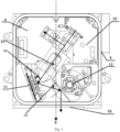
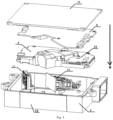
- Fig. 4 shows an inverted placement of the LiDAR in Fig. 1 . That is, Fig. 4 shows a structure of the LiDAR when placed upside down. To facilitate the description of an internal structural arrangement of the LiDAR, the exploded structure shown in Fig. 4 is selected to introduce the complete structure of the LiDAR in the embodiments of this disclosure.
- Reference number 70 in Fig. 1 denotes a top plate of the LiDAR
- oppositely reference number 71 in Fig. 4 denotes a bottom plate of the LiDAR.
- Fig. 1 it can be seen that for the LiDAR provided in the embodiments of this disclosure, due to the flat design of the internal structure and the compact mounting of various functional components, the height of the assembled LiDAR is sufficiently low, the overall structure is miniaturized, the mounting requirements of the vehicle body can be met, and the compatibility and integration with the vehicle body are achieved.
- the emitter module 2 and the receiver module 3 are arranged on two sides of the optomechanics module 4 , respectively; and the emitter module 2, the receiver module 3, and the scanner module 1 are arranged within the preset height of the optomechanics module 4, so that the size of the LiDAR in the height direction is smaller than the size thereof in width and length directions.
- the size of an existing scanning LiDAR in the height direction is at least 50 mm.
- the size of the LiDAR in the height direction in this disclosure is reduced by about 50% compared with the size of the existing scanning LiDAR in the height direction, making the overall size of the LiDAR close to two-dimensional.
- the LiDAR in this disclosure uses two scanner modules 1 for scanning, where the two scanner modules 1 are arranged in the plane perpendicular to the height direction of the LiDAR. Extension directions of the emitter module 2 and the receiver module 3, and an arrangement direction of optics devices 5 in a coaxial light path are perpendicular to the height direction of the LiDAR.
- Each optics device 5 is arranged in the optomechanics module 4.
- the emitter module 2 and the receiver module 3 are arranged on different sides of the optomechanics module 4.
- a light homogenizing component 53 arranged close to one end of the emitter module 2 is configured to change a shape of a light spot formed by the detection laser beam. The detection laser beam after change of the shape of the light spot cooperates with the two scanner modules 1 to scan and cover a detection field of view.
- the scanner module 1 includes a first scanner module 11 and a second scanner module 12 that are mounted inside the LiDAR, where the scanner module 1 determines the height of the LiDAR, and other components of the LiDAR, such as the optics device 5 and the optomechanics module for mounting the optics device 5, are limited by product performance requirements and do not have many design changes in size, so that it is needed to reduce the height of the scanner module 1 to the height of the optics device 5 and the optomechanics module as much as possible, thereby reducing the overall height of the LiDAR.
- a ratio of the height of the scanner module 1 to the height of the LiDAR is set to be greater than or equal to 0.72, that is, the height of the scanner module 1 is approximately equal to the height of the LiDAR.
- the first scanner module 11 and the second scanner module 12 are arranged in the plane perpendicular to the height direction (the direction indicated by the arrow H) of the LiDAR, which also helps to reduce the height of the LiDAR.
- the detection laser beam emitted is scanned by the first scanner module 11 and reflected to the second scanner module 12.
- the second scanner module 12 scans the detection laser beam and reflects it to a window 10.
- the detection laser beam is emitted from the window 10 to the outside of the LiDAR for detecting a surrounding object.
- the reflected echo laser beam reaches the window 10 and then sequentially passes through the second scanner module 12 and the first scanner module 11, and the received echo laser beam is reflected to the receiver module 3 of the LiDAR for subsequent processing.
- Fig. 4 For specific mounting of various structures, reference can be made to Fig. 4 .
- the scanner module 1 i.e., the first scanner module 11 and the second scanner module 12
- various other functional modules of the LiDAR provided in the embodiments of this disclosure are sequentially mounted in the direction of the arrow N as shown in the figure.
- the overall height of the LiDAR can be reduced while there can be sufficient spaces inside the LiDAR for mounting the optomechanics module 4 and various functional components thereon.
- the scanner module 1 occupying a small space in the LiDAR is placed close to the light-emitting side of the housing 9 of the LiDAR and the window 10, and the optomechanics module 4 occupying a large space and the various functional components thereon are placed in a middle of the LiDAR, so that an arrangement angle of the scanner module 1 occupying the small space can be changed and matches with an arrangement angle of the optomechanics module 4 occupying the large space to achieve minimum envelope assembly of all functional modules.
- the ratio of the height of the scanner module 1 to the height of the LiDAR can also be set to be greater than or equal to 0.8 and less than or equal to 0.95.
- the overall height of the LiDAR is changed based on the specific height of the scanner module 1 to achieve miniaturization of the LiDAR as a whole.
- the height of the scanner module 1 is set to be close to the height of the LiDAR, so that the height of the scanner module 1 mounted inside the LiDAR is reduced, thereby reducing the height of the overall structure of the LiDAR. It can be seen that in the LiDAR provided in the embodiments of this disclosure, the height of the scanner module 1 is made close to that of the LiDAR by reducing the height of the scanner module 1, so that the height of the overall structure of the LiDAR can be reduced, thereby miniaturizing the LiDAR in structure, facilitating the assembly and production of the LiDAR, meeting the requirements for the mounting environment in the vehicle body, and making it easy to be compatible with and integrate with the vehicle body.
- two one-dimensional scanner modules 1 are used to replace one two-dimensional scanner module 1.
- the optomechanics module and the two-dimensional scanner module 1 are typically arranged along the height direction of the LiDAR (i.e., the two are arranged one above the other in the height direction of the LiDAR), and the first scanner module 11 and the second scanner module 12 are arranged in the plane perpendicular to the height direction of the LiDAR, which helps to reduce the height of the LiDAR.
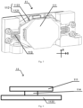
- Fig. 5 shows a schematic structural diagram of a first scanner module of a LiDAR, provided in embodiments of this disclosure.
- Fig. 6 shows another schematic structural diagram of a first scanner module of a LiDAR, provided in embodiments of this disclosure.
- Fig. 7 shows a schematic structural diagram of a second scanner module of a LiDAR, provided in embodiments of this disclosure.
- Fig. 8 shows a schematic diagram of an arrangement structure of a coaxial light path of a LiDAR, provided in embodiments of this disclosure.
- the first direction can be a horizontal direction
- the second direction can be a vertical direction
- the schematic structural diagram shown in Fig. 6 is a schematic sectional view of the first scanner module 11. It can be seen that in this schematic sectional view, a bottom structure of the first scanner module 11 is the fixing component 1122, a middle structure is a separation layer 114, and an uppermost structure is the first scanning mirror 111.
- the second driver device 122 can be a driving motor, such as a resonant voice coil motor.
- the second driver device 122 drives the second scanning mirror 121 to reciprocate with the rotating shaft F as the axis.
- a motion region of the second scanning mirror 121 only needs to be set based on the actual scanning field-of-view angle of the LiDAR in the second direction, and the second scanning mirror 121 does not scan at other angles outside the scanning field-of-view angle in the second direction.
- the second scanner module 12 achieves scanning of the laser beam in the second direction.
- a scanning speed of the first scanner module 11 and a scanning speed of the second scanner module 12 can be specifically set based on the first driver device 112 and the second driver device 122. Based on the actual requirements, in some embodiments, the driving scanning speed of the first driver device 112 along the first direction A can be set to be greater than the driving scanning speed of the second driver device 122 along the second direction B.
- an angle between an optical axis of the laser beam emitted from the optomechanics module 4 and directed onto a first scanning mirror 111 of the first scanner module 11 and the first scanning mirror 111 at an initial position ranges from 50° to 60°.
- the set angle of the second scanner module 12 is further set in combination with the set angle of the first scanner module 11, so that the envelope of the internal depth and width of the LiDAR is minimized.
- Fig. 10 shows a schematic scanning diagram of a scanning field of view of a LiDAR, provided in embodiments of this disclosure.
- the first laser group and the second laser group can emit the detection laser beams in a time-dividing manner.
- the lasers 21 in the first laser group simultaneously emit the detection laser beams to form a light spot in the scanning field of view, such as A-1.
- the lasers 21 in the second laser group simultaneously emit the detection laser beams to form a light spot in the scanning field of view, such as B-1.
- the optics devices 5 inside the LiDAR are arranged in the direction perpendicular to the height of the LiDAR. Moreover, to ensure that the detection laser beam emitted from the emitter module 2 and the echo laser beam received by the receiver module 3 need to be transmitted by the optics devices 5 in the optomechanics module 4, it is needed to set the emitter module 2, the receiver module 3, and the optics devices 5 in a coaxial light path. Specifically, reference continues to be made to Fig. 8 . Due to the characteristics of the coaxial light path, emitting and receiving light paths (laser beam transmission paths for the detection laser beam and the echo laser beam) need to be located in a same horizontal plane.
- the receiving deflecting mirror 51 is used to deflect the echo laser beam in the receiving light path by 90°, so that the receiver board 32 is arranged in the direction perpendicular to the height of the LiDAR, the echo laser beam can be vertically directed onto the receiver module 3, and the height of the LiDAR can be reduced without affecting reliable operation of the LiDAR.
- the optics device 5 can further include a light homogenizing component 53 arranged close to one end of the emitter module 2 and configured to change a shape of a light spot formed by the detection laser beam. Specifically, the shape of the light spot formed by the multiple detection laser beams T emitted from each laser group is changed.
- the cylindrical lens array includes multiple cylindrical lens units 530.
- the cylindrical lens array includes multiple cylindrical lens units 530.
- the cylindrical lens units 530 are arranged in sequence along a height direction of the LiDAR, and the cylindrical lens units 530 can change the shape of the light spot formed by the detection laser beam.
- the detection laser beams emitted in a time-dividing manner from different laser groups of the LiDAR can be homogenized by the multiple cylindrical lens units, so that the multiple detection laser beams are changed to form the uniform light spot (e.g., the linear light spot.).
- a diaphragm can further be arranged directly in front of the detector 31 to reduce the impact of ambient light on the echo laser beam.
- a collimator unit can further be added. Specifically, reference continues to be made to FIG. 8 .
- the optics device 5 further includes
- the fast-axis collimating lens 541 (“FAC”) and the slow-axis collimating lens 542 (“SAC”) can reduce the divergence angle of the detection laser beam and achieve change of the light spot of the detection laser beam from an elliptical shape to an approximately circular shape. Moreover, the use of the fast-axis collimating lens 541 (“FAC”) and the slow-axis collimating lens 542 (“SAC”) facilitates mounting as well as automated assembly.
- the extension directions of both the emitter module 2 and the receiver module 3 are perpendicular to the height direction of the LiDAR (shown in Fig. 11a and Fig. 12 .).
- the planes where the emitter module 2 and the receiver module 3 are arranged can be set parallel to a plane where the optomechanics module 4 is arranged(shown in Fig. 11a and Fig. 12 .).
- the positions of the receiver module 3 and the emitter module 2 are reasonably arranged to reduce the height of the LiDAR.
- the emitter module 2 and the receiver module 3 are arranged on the same side of the optomechanics module 4.
- the emitter board 22 and the receiver board 32 are arranged on the same side of the optomechanics module 4, such as on a lower side in Fig. 12 .
- the optics device 5 further includes: an emitting deflecting mirror arranged adjacent to the emitter module 2 along a height direction of the LiDAR and configured to reflect the detection laser beam through the optomechanics module 4 and vertically direct the detection laser beam onto the optics device 5 of the optomechanics module 4.
- the emitting deflecting mirror is used to deflect the detection laser beam in the emitting light path by 90°, so that the detection laser beam can be vertically directed onto the optics device 5 in the optomechanics module 4, and the height of the LiDAR can be reduced without affecting reliable operation of the LiDAR.
- the optomechanics module 4 includes the emitter module 2 (including the laser 21 and the emitter board 22), the receiver module 3 (including the detector 31 and the receiver board 32), and the optics device 5.
- the coaxial light path includes the laser 21 mounted on the emitter board 22, the fast-axis collimating lens 541, the light homogenizing component 53, the slow-axis collimating lens 542, and the receiving deflecting mirror 51.
- the optomechanics module 4 includes a lens barrel 41 and a mounter unit 42, and the optics device 5 further includes:
- the positive lens 55 the wave plate 56, the first negative lens 57, the second negative lens 58, and the beam splitter unit 59, reference can continue to be made to Fig. 8 , and they are also optical components in the coaxial light path.
- the positive lens 55, the wave plate 56, and the first negative lens 57 have large mirror surface areas, so that during assembly, it is needed to take into account the risk of thermal stress caused by adhesion between lens elements of the positive lens 55, the wave plate 56, and the first negative lens 57 and the lens barrel 41 for fixing the lens elements, and reduce cut edges and cut edge adhesion of the lens elements as much as possible. Accordingly, a structure for fixation by the lens barrel 41 is used to adhere arc surfaces of the lens elements.
- these lens elements can be fixed by the mounter unit 42 because they have small areas and are mostly not cut from circular lens elements.
- the detection laser beam first passes through the fast-axis collimating lens 541, then is homogenized by the light homogenizing component 53, passes through the slow-axis collimating lens 542, is emitted to the beam splitter unit 59, passes through the first negative lens 57, the wave plate 56, and the positive lens 55, and is scanned by the first scanning mirror 111 in the first direction A and reflected to the second scanning mirror 121, and the second scanning mirror 121 scans the detection laser beam in the second direction B and reflects it to the outside of the LiDAR.
- the echo laser beam is reflected.
- the second scanning mirror 121 receives the echo laser beam and reflects it to the first scanning mirror 111.
- the echo laser beam is reflected to the positive lens 55, the wave plate 56, and the first negative lens 57.
- the beam splitter unit 59 the echo laser beam is reflected to the light filter 52, the second negative lens 58, and the receiving deflecting mirror 51. After being deflected by the receiving deflecting mirror 51, the echo laser beam is vertically reflected onto the detector 31.
- such an arrangement can improve the positioning accuracy and thermal adaptability between the emitter board 22 and the optics device 5.
- the mounter unit 42 and the lens barrel 41 are of an integrally formed structure (i.e., the lens barrel structure of optical components 6), in an embodiment, the mounter unit 42 and the lens barrel 41 are located on the same surface of the optomechanics module 4.
Landscapes
- Engineering & Computer Science (AREA)
- Physics & Mathematics (AREA)
- Computer Networks & Wireless Communication (AREA)
- General Physics & Mathematics (AREA)
- Radar, Positioning & Navigation (AREA)
- Remote Sensing (AREA)
- Electromagnetism (AREA)
- Optical Radar Systems And Details Thereof (AREA)
Applications Claiming Priority (2)
| Application Number | Priority Date | Filing Date | Title |
|---|---|---|---|
| CN202211048493.7A CN117665753A (zh) | 2022-08-30 | 2022-08-30 | 激光雷达 |
| PCT/CN2023/078590 WO2024045520A1 (zh) | 2022-08-30 | 2023-02-28 | 激光雷达 |
Publications (2)
| Publication Number | Publication Date |
|---|---|
| EP4582834A1 true EP4582834A1 (de) | 2025-07-09 |
| EP4582834A4 EP4582834A4 (de) | 2026-01-21 |
Family
ID=90071923
Family Applications (1)
| Application Number | Title | Priority Date | Filing Date |
|---|---|---|---|
| EP23858563.2A Pending EP4582834A4 (de) | 2022-08-30 | 2023-02-28 | Laserradar |
Country Status (4)
| Country | Link |
|---|---|
| US (1) | US20250199131A1 (de) |
| EP (1) | EP4582834A4 (de) |
| CN (1) | CN117665753A (de) |
| WO (1) | WO2024045520A1 (de) |
Family Cites Families (14)
| Publication number | Priority date | Publication date | Assignee | Title |
|---|---|---|---|---|
| JP6819098B2 (ja) * | 2016-07-01 | 2021-01-27 | 株式会社リコー | 物体検出装置、センシング装置及び移動体装置 |
| CN107085207B (zh) * | 2017-04-01 | 2020-05-01 | 北京图来激光科技有限公司 | 一种360°扫描探测激光雷达装置 |
| CN207488485U (zh) * | 2017-08-02 | 2018-06-12 | 周虎基 | 回波信号采集装置 |
| WO2019109993A1 (zh) * | 2017-12-08 | 2019-06-13 | 上海禾赛光电科技有限公司 | 激光雷达系统及其控制方法、扫描角度的获取方法及车辆 |
| CN109343226A (zh) * | 2018-11-22 | 2019-02-15 | 常州英诺激光科技有限公司 | 一种将激光光斑转化成均匀线列光斑的光学系统 |
| CN109270515B (zh) * | 2018-11-29 | 2020-06-16 | 北京理工大学 | 可变扫描区域同轴收发扫描激光雷达 |
| CN109239693B (zh) * | 2018-11-29 | 2020-08-11 | 北京理工大学 | 收发共路扫描激光雷达 |
| CN112327275B (zh) * | 2019-01-07 | 2022-08-02 | 上海禾赛科技有限公司 | 一种激光雷达 |
| CN112147636B (zh) * | 2019-06-26 | 2024-04-26 | 华为技术有限公司 | 一种激光雷达及激光雷达的探测方法 |
| CN110346811B (zh) * | 2019-08-08 | 2022-05-06 | 上海禾赛科技有限公司 | 激光雷达及其探测装置 |
| CN212060560U (zh) * | 2020-01-06 | 2020-12-01 | 北京北科天绘科技有限公司 | 具有对称收发光路的光学系统、激光雷达及智能车、无人机 |
| CN214669609U (zh) * | 2021-03-08 | 2021-11-09 | 上海禾赛科技有限公司 | 激光雷达及其收发模块 |
| CN113589256A (zh) * | 2021-07-23 | 2021-11-02 | 苏州光之矩光电科技有限公司 | 一种分视场多面转镜的无人驾驶用激光雷达 |
| CN114114320B (zh) * | 2021-12-22 | 2026-01-23 | 上海禾赛科技有限公司 | 激光收发组件及激光雷达 |
-
2022
- 2022-08-30 CN CN202211048493.7A patent/CN117665753A/zh active Pending
-
2023
- 2023-02-28 EP EP23858563.2A patent/EP4582834A4/de active Pending
- 2023-02-28 WO PCT/CN2023/078590 patent/WO2024045520A1/zh not_active Ceased
-
2025
- 2025-02-28 US US19/066,755 patent/US20250199131A1/en active Pending
Also Published As
| Publication number | Publication date |
|---|---|
| EP4582834A4 (de) | 2026-01-21 |
| US20250199131A1 (en) | 2025-06-19 |
| WO2024045520A1 (zh) | 2024-03-07 |
| CN117665753A (zh) | 2024-03-08 |
Similar Documents
| Publication | Publication Date | Title |
|---|---|---|
| CN107561551B (zh) | 一种基于多线激光雷达的光路系统 | |
| US20230145710A1 (en) | Laser receiving device, lidar, and intelligent induction apparatus | |
| CN111381218B (zh) | 一种混合固态激光雷达及其制造方法和探测方法 | |
| WO2025113566A1 (en) | Optical scanner system for lidar and lidar | |
| CN114114320A (zh) | 激光收发组件及激光雷达 | |
| CN211402711U (zh) | 一种激光雷达 | |
| CN221946172U (zh) | 固态激光雷达 | |
| EP4582834A1 (de) | Laserradar | |
| CN115980709B (zh) | 激光雷达探测方法 | |
| CN110596675A (zh) | 一种激光发射装置及激光雷达系统 | |
| CN222232674U (zh) | 激光雷达 | |
| CN220491038U (zh) | 一种多点激光测距装置 | |
| CN219285418U (zh) | 一种激光雷达 | |
| EP4641850A1 (de) | Emittierende vorrichtung, detektionsvorrichtung und endgerät | |
| CN217112718U (zh) | 一种镜片组件及激光雷达 | |
| CN116840846A (zh) | 激光雷达 | |
| CN116359880A (zh) | 激光发射装置和激光雷达 | |
| CN120322694A (zh) | 一种发射装置、探测装置和终端 | |
| CN118011360A (zh) | 激光雷达 | |
| CN116953713B (zh) | 激光收发结构以及激光雷达 | |
| CN221126534U (zh) | 光学组件、光发射装置、激光雷达及结构光装置 | |
| CN223401039U (zh) | 一种激光雷达及自动驾驶设备 | |
| US20250306174A1 (en) | LiDAR and Autonomous Driving Apparatus | |
| CN223857398U (zh) | 一种激光雷达以及自移动设备 | |
| CN220154640U (zh) | 用于激光雷达的光发射模块和激光雷达 |
Legal Events
| Date | Code | Title | Description |
|---|---|---|---|
| STAA | Information on the status of an ep patent application or granted ep patent |
Free format text: STATUS: THE INTERNATIONAL PUBLICATION HAS BEEN MADE |
|
| PUAI | Public reference made under article 153(3) epc to a published international application that has entered the european phase |
Free format text: ORIGINAL CODE: 0009012 |
|
| STAA | Information on the status of an ep patent application or granted ep patent |
Free format text: STATUS: REQUEST FOR EXAMINATION WAS MADE |
|
| 17P | Request for examination filed |
Effective date: 20250326 |
|
| AK | Designated contracting states |
Kind code of ref document: A1 Designated state(s): AL AT BE BG CH CY CZ DE DK EE ES FI FR GB GR HR HU IE IS IT LI LT LU LV MC ME MK MT NL NO PL PT RO RS SE SI SK SM TR |
|
| DAV | Request for validation of the european patent (deleted) | ||
| DAX | Request for extension of the european patent (deleted) | ||
| A4 | Supplementary search report drawn up and despatched |
Effective date: 20251222 |
|
| RIC1 | Information provided on ipc code assigned before grant |
Ipc: G01S 7/481 20060101AFI20251216BHEP Ipc: G01S 17/931 20200101ALI20251216BHEP |