EP4582849A2 - Unité de génération d'image tête haute avec miroir pliant - Google Patents
Unité de génération d'image tête haute avec miroir pliant Download PDFInfo
- Publication number
- EP4582849A2 EP4582849A2 EP25172155.1A EP25172155A EP4582849A2 EP 4582849 A2 EP4582849 A2 EP 4582849A2 EP 25172155 A EP25172155 A EP 25172155A EP 4582849 A2 EP4582849 A2 EP 4582849A2
- Authority
- EP
- European Patent Office
- Prior art keywords
- light
- mirror
- angle
- gaps
- folding mirror
- Prior art date
- Legal status (The legal status is an assumption and is not a legal conclusion. Google has not performed a legal analysis and makes no representation as to the accuracy of the status listed.)
- Pending
Links
Images



Classifications
-
- G—PHYSICS
- G02—OPTICS
- G02B—OPTICAL ELEMENTS, SYSTEMS OR APPARATUS
- G02B27/00—Optical systems or apparatus not provided for by any of the groups G02B1/00 - G02B26/00, G02B30/00
- G02B27/01—Head-up displays
- G02B27/0101—Head-up displays characterised by optical features
-
- B—PERFORMING OPERATIONS; TRANSPORTING
- B60—VEHICLES IN GENERAL
- B60K—ARRANGEMENT OR MOUNTING OF PROPULSION UNITS OR OF TRANSMISSIONS IN VEHICLES; ARRANGEMENT OR MOUNTING OF PLURAL DIVERSE PRIME-MOVERS IN VEHICLES; AUXILIARY DRIVES FOR VEHICLES; INSTRUMENTATION OR DASHBOARDS FOR VEHICLES; ARRANGEMENTS IN CONNECTION WITH COOLING, AIR INTAKE, GAS EXHAUST OR FUEL SUPPLY OF PROPULSION UNITS IN VEHICLES
- B60K35/00—Instruments specially adapted for vehicles; Arrangement of instruments in or on vehicles
- B60K35/20—Output arrangements, i.e. from vehicle to user, associated with vehicle functions or specially adapted therefor
- B60K35/21—Output arrangements, i.e. from vehicle to user, associated with vehicle functions or specially adapted therefor using visual output, e.g. blinking lights or matrix displays
- B60K35/23—Head-up displays [HUD]
-
- G—PHYSICS
- G02—OPTICS
- G02B—OPTICAL ELEMENTS, SYSTEMS OR APPARATUS
- G02B19/00—Condensers, e.g. light collectors or similar non-imaging optics
- G02B19/0004—Condensers, e.g. light collectors or similar non-imaging optics characterised by the optical means employed
- G02B19/0019—Condensers, e.g. light collectors or similar non-imaging optics characterised by the optical means employed having reflective surfaces only (e.g. louvre systems, systems with multiple planar reflectors)
-
- G—PHYSICS
- G02—OPTICS
- G02B—OPTICAL ELEMENTS, SYSTEMS OR APPARATUS
- G02B27/00—Optical systems or apparatus not provided for by any of the groups G02B1/00 - G02B26/00, G02B30/00
- G02B27/28—Optical systems or apparatus not provided for by any of the groups G02B1/00 - G02B26/00, G02B30/00 for polarising
- G02B27/283—Optical systems or apparatus not provided for by any of the groups G02B1/00 - G02B26/00, G02B30/00 for polarising used for beam splitting or combining
- G02B27/285—Optical systems or apparatus not provided for by any of the groups G02B1/00 - G02B26/00, G02B30/00 for polarising used for beam splitting or combining comprising arrays of elements, e.g. microprisms
-
- G—PHYSICS
- G02—OPTICS
- G02B—OPTICAL ELEMENTS, SYSTEMS OR APPARATUS
- G02B27/00—Optical systems or apparatus not provided for by any of the groups G02B1/00 - G02B26/00, G02B30/00
- G02B27/28—Optical systems or apparatus not provided for by any of the groups G02B1/00 - G02B26/00, G02B30/00 for polarising
- G02B27/286—Optical systems or apparatus not provided for by any of the groups G02B1/00 - G02B26/00, G02B30/00 for polarising for controlling or changing the state of polarisation, e.g. transforming one polarisation state into another
-
- G—PHYSICS
- G02—OPTICS
- G02B—OPTICAL ELEMENTS, SYSTEMS OR APPARATUS
- G02B5/00—Optical elements other than lenses
- G02B5/08—Mirrors
- G02B5/09—Multifaceted or polygonal mirrors, e.g. polygonal scanning mirrors; Fresnel mirrors
-
- B—PERFORMING OPERATIONS; TRANSPORTING
- B60—VEHICLES IN GENERAL
- B60K—ARRANGEMENT OR MOUNTING OF PROPULSION UNITS OR OF TRANSMISSIONS IN VEHICLES; ARRANGEMENT OR MOUNTING OF PLURAL DIVERSE PRIME-MOVERS IN VEHICLES; AUXILIARY DRIVES FOR VEHICLES; INSTRUMENTATION OR DASHBOARDS FOR VEHICLES; ARRANGEMENTS IN CONNECTION WITH COOLING, AIR INTAKE, GAS EXHAUST OR FUEL SUPPLY OF PROPULSION UNITS IN VEHICLES
- B60K2360/00—Indexing scheme associated with groups B60K35/00 or B60K37/00 relating to details of instruments or dashboards
- B60K2360/20—Optical features of instruments
- B60K2360/23—Optical features of instruments using reflectors
-
- B—PERFORMING OPERATIONS; TRANSPORTING
- B60—VEHICLES IN GENERAL
- B60K—ARRANGEMENT OR MOUNTING OF PROPULSION UNITS OR OF TRANSMISSIONS IN VEHICLES; ARRANGEMENT OR MOUNTING OF PLURAL DIVERSE PRIME-MOVERS IN VEHICLES; AUXILIARY DRIVES FOR VEHICLES; INSTRUMENTATION OR DASHBOARDS FOR VEHICLES; ARRANGEMENTS IN CONNECTION WITH COOLING, AIR INTAKE, GAS EXHAUST OR FUEL SUPPLY OF PROPULSION UNITS IN VEHICLES
- B60K2360/00—Indexing scheme associated with groups B60K35/00 or B60K37/00 relating to details of instruments or dashboards
- B60K2360/20—Optical features of instruments
- B60K2360/25—Optical features of instruments using filters
-
- G—PHYSICS
- G02—OPTICS
- G02B—OPTICAL ELEMENTS, SYSTEMS OR APPARATUS
- G02B27/00—Optical systems or apparatus not provided for by any of the groups G02B1/00 - G02B26/00, G02B30/00
- G02B27/01—Head-up displays
- G02B27/0101—Head-up displays characterised by optical features
- G02B2027/0118—Head-up displays characterised by optical features comprising devices for improving the contrast of the display / brillance control visibility
-
- G—PHYSICS
- G02—OPTICS
- G02B—OPTICAL ELEMENTS, SYSTEMS OR APPARATUS
- G02B27/00—Optical systems or apparatus not provided for by any of the groups G02B1/00 - G02B26/00, G02B30/00
- G02B27/01—Head-up displays
- G02B27/0101—Head-up displays characterised by optical features
- G02B2027/0127—Head-up displays characterised by optical features comprising devices increasing the depth of field
Definitions
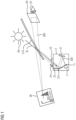
- the present invention relates to a head-up display having an image generation unit with a folding mirror.
- a head-up display also known as a HUD, is a display system that allows the viewer to maintain their line of sight by projecting the content into their field of vision. While such systems were originally used primarily in aviation due to their complexity and cost, they are now also being installed in large-scale production in the automotive sector.
- Head-up displays generally consist of an imaging unit or PGU (Picture Generating Unit), an optical unit, and a mirror unit.
- the imaging unit generates the image using at least one display element.
- Most modern head-up displays use LCD-based displays (LCD: Liquid Crystal Display) to generate the image.
- LCD Liquid Crystal Display
- the optical unit directs the image onto the mirror unit.
- the mirror unit is a partially reflective, translucent pane. The viewer therefore sees the content displayed by the imaging unit as a virtual image and, at the same time, the real world behind the pane. In the automotive sector, the windshield is often used as the mirror unit, and its curved shape must be taken into account when displaying the image.
- the interaction of the optical unit and the mirror unit results in the virtual image being an enlarged representation of the image generated by the imaging unit.
- the US 5,313,326 A , the WO 2014/041689 A , the US 2015/0362221 A1 and the US 2018/252917 A1 show head-up displays that use a folding mirror whose angle of incidence and angle of reflection are unequal.
- the folding mirror whose angle of incidence and angle of reflection are unequal, is positioned in the image path. This property can have an adverse effect on image quality and/or sensitivity to stray light.
- a backlight for a liquid crystal display is known in which one edge of a light guide is provided with a multitude of reflective surfaces that expand a tightly focused laser beam into a wide beam of light.
- a laser light source in head-up displays is mainly known for micro-mirror units (so-called DMDs, or Digital Micro Mirror Devices), which require a light beam with a very small cross-section and a narrow aperture angle.
- a head-up display in which an optical element comprises a mirror with microstructures that project light onto a display element.
- a disadvantage is that the illumination of the display element is uneven, with dark stripes.
- a head-up display in which a liquid crystal display element is designed to use as much of the unpolarized light generated by a light source as possible by means of a polarization converter.
- a head-up display that is improved compared to the known head-up displays is desired.
- a head-up display according to the invention is specified in claim 1.
- the head-up display has an imaging unit for generating an image and an optical unit for projecting the image through a mirror unit.
- the imaging unit has a folding mirror.
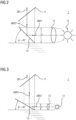
- the folding mirror is arranged between a light source and a display element illuminated by the light source, at an angle of incidence to the propagation direction of the light incident on it from the light source. The angle of incidence is preferably less than 45°, which allows for a flatter installation space.
- the folding mirror has microstructures.
- the microstructures have first mirror surfaces, which are arranged at a first angle different from the angle of incidence of the folding mirror and are spaced from one another to form gaps. Second surfaces are arranged in the gaps at a second angle.
- a polarizer directs light of a first polarization to the display element and light of a second polarization into the gaps.
- a retarder converts the polarization of the light directed into the gaps into the first polarization.
- the light directed into the gaps is then guided towards the display element after passing through them.
- This has the advantage of achieving polarization recycling, and also allowing light from the gaps to reach the display element.
- only one of the polarization directions generated by the light source is used if the display element is a linearly polarized light modulating display element. This is the case, for example, with liquid crystal displays (LCDs).
- the normally unused polarization is converted into the polarization required by the display element by means of a polarizer and retarder, exploiting the gaps in the folding mirror and then guided to the latter.
- the light directed into and passing through the gaps has the same polarization as the light polarized by the mirror surfaces.
- the display element is thus illuminated seamlessly with light of a single polarization.
- this also eliminates the need for additional homogenization measures.
- Such an ideal case exists, for example, for certain duty cycles.
- the stripe structure is further blurred with scatterers, for example. Such scattering also serves to illuminate the eyebox.
- the first mirror surfaces have different first angles among one another. Groups of first mirror surfaces with the same first angles can also have different first angles from group to group. In particular, however, each first playing surface has a different first angle than the other first mirror surfaces.
- the first mirror surfaces are designed as reflective polarizers, and the gaps are designed as retarders that rotate the polarization direction by 90°.
- a retarder is also referred to as a ⁇ /2 plate or half-wave plate.
- This variant according to the invention has the advantage of combining the functions of reflecting light at the mirror surfaces and filling the gaps between the mirror surfaces with light in a single component that can be separately prefabricated and tested. This also facilitates assembly.
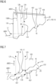
- the folding mirror has two parallel interfaces, both of which have the same microstructures arranged offset from one another.
- This configuration is particularly advantageous when gaps and mirror surfaces have the same extent when projected onto the direction of light propagation.
- the offset is then advantageously as large as this extent or an integer multiple thereof.
- Another advantage here is that the folding mirror can be manufactured in a single process, eliminating the need to adjust the macrostructures to one another.
- the folding mirror has two mutually parallel interfaces, of which the upper interface has first mirror surfaces and the lower interface has first mirror surfaces.
- the first mirror surfaces of the lower interface have different second angles among one another. For example, this can be achieved by having several groups of first mirror surfaces, in which the mirror surfaces of a group each have the same second angle, but the second angles differ from group to group.
- each of the first mirror surfaces of the lower interface has a different second angle than the other first mirror surfaces. This has the advantage that a fanned-out radiation or astigmatism is also achieved by means of the first mirror surfaces of the lower interface.
- Each of the first mirror surfaces of the lower interface has an angle, which is referred to as the second angle, and whose value lies between the values of the angles of two adjacent first mirror surfaces of the upper interface.
- the angle of the first mirror surfaces of the upper interface is referred to as the first angle.
- the polarizer is designed as a reflective polarizer and arranged between the folding mirror and the display element.
- the retarder is a retarder that converts linear polarization into circular polarization and is passed through by the light twice. Such a retarder is also referred to as a ⁇ /4 plate or quarter-wave plate.
- a lambda/2 retarder is split, and the delay is distributed over two passes.
- the retarder in this variant is arranged between the folding mirror and the polarizer. This has the advantage that the components can be designed as a flat surface, allowing the use of cost-effective, mass-produced components.
- the input-side polarizer of a display element that requires polarized input light is advantageously used as the polarizer. This saves components and, due to the fewer interfaces the light must pass through, also results in lower light output losses and less interference.
- the polarizer and retarder are also advantageously designed as a single piece as a reflective circular polarizer.
- the reflective polarizer is inclined at an angle other than 90° to the propagation direction of the light incident on it from the folding mirror, and the second reflective surfaces are arranged parallel to the reflective polarizer.
- This has the advantage that light reflected by the reflective polarizer, which is not or hardly divergent, is not reflected back onto the first mirror surfaces, but rather, with a suitable choice of angle and spacing, onto one of the second reflective surfaces in the gaps. From these, it is reflected parallel to the light reflected by the first mirror surfaces towards the polarizer, from which it is transmitted after the polarization direction has been adjusted by means of the retarder.
- a very large proportion of the light of both polarizations is utilized, and almost no dark areas are caused by the gaps.
- the display element is illuminated very homogeneously.
- the folding mirror is part of a transparent body with a wedge-shaped cross-section, in which the wedge base is the light entry surface facing the light source, the microstructures are arranged on one of the large side surfaces of the wedge, and the other large side surface of the wedge is the light exit surface facing the display element.
- the transparent body is a large-volume component that is less vulnerable than very thin components, which simplifies handling during production.
- the transparent body is cast in a large mold, for example, and subsequently provided with polarizer functionality and retarder functionality on the light exit surface, for example with an appropriate coating.
- Second reflecting surfaces which in pairs form a retroreflector.
- Such an arrangement is robust against angular tilt. Even if the reflector is not precisely aligned with the incident light, Folding mirrors reflect the light so that the outgoing light is parallel to the incoming light.
- the first mirror surfaces have different angles to one another. This can be done in groups, as mentioned above.
- each of the first mirror surfaces has a different first angle
- the reflective polarizer has first polarizer surfaces and second polarizer surfaces, each of which forms a retroreflector in pairs.
- the light fanned out by the first mirror surfaces is reflected by 180° when reflected by the reflective polarizer, regardless of the angle at which it hits the reflective polarizer.
- Reflection by the second surfaces also occurs by 180° if these are also designed as retroreflectors.
- the angular fanning caused by the first mirror surfaces is therefore retained even after this double reflection; the light with rotated polarization then passes through the reflective polarizer at the same angle as the light that was already polarized enough to pass through the reflective polarizer when it first hit it.
- a fanned-out radiation or astigmatism is realized, which is desirable in certain conditions of a head-up display.
- This advantage also occurs when, in general, a folding mirror in a head-up display is aligned parallel to a display element of this head-up display, with the property that the angle of incidence and the angle of reflection are macroscopically unequal.
Landscapes
- Physics & Mathematics (AREA)
- General Physics & Mathematics (AREA)
- Optics & Photonics (AREA)
- Engineering & Computer Science (AREA)
- Chemical & Material Sciences (AREA)
- Combustion & Propulsion (AREA)
- Transportation (AREA)
- Mechanical Engineering (AREA)
- Devices For Indicating Variable Information By Combining Individual Elements (AREA)
- Instrument Panels (AREA)
Applications Claiming Priority (3)
| Application Number | Priority Date | Filing Date | Title |
|---|---|---|---|
| DE102021214549.3A DE102021214549B3 (de) | 2021-12-16 | 2021-12-16 | Head-Up-Display Bilderzeugungseinheit mit Faltspiegel |
| DE102022201673 | 2022-02-17 | ||
| EP22211118.9A EP4198610B1 (fr) | 2021-12-16 | 2022-12-02 | Unité de génération d'image tête haute avec miroir pliant |
Related Parent Applications (2)
| Application Number | Title | Priority Date | Filing Date |
|---|---|---|---|
| EP22211118.9A Division EP4198610B1 (fr) | 2021-12-16 | 2022-12-02 | Unité de génération d'image tête haute avec miroir pliant |
| EP22211118.9A Division-Into EP4198610B1 (fr) | 2021-12-16 | 2022-12-02 | Unité de génération d'image tête haute avec miroir pliant |
Publications (2)
| Publication Number | Publication Date |
|---|---|
| EP4582849A2 true EP4582849A2 (fr) | 2025-07-09 |
| EP4582849A3 EP4582849A3 (fr) | 2025-09-03 |
Family
ID=84387887
Family Applications (2)
| Application Number | Title | Priority Date | Filing Date |
|---|---|---|---|
| EP22211118.9A Active EP4198610B1 (fr) | 2021-12-16 | 2022-12-02 | Unité de génération d'image tête haute avec miroir pliant |
| EP25172155.1A Pending EP4582849A3 (fr) | 2021-12-16 | 2022-12-02 | Unité de génération d'image tête haute avec miroir pliant |
Family Applications Before (1)
| Application Number | Title | Priority Date | Filing Date |
|---|---|---|---|
| EP22211118.9A Active EP4198610B1 (fr) | 2021-12-16 | 2022-12-02 | Unité de génération d'image tête haute avec miroir pliant |
Country Status (3)
| Country | Link |
|---|---|
| US (1) | US20230194862A1 (fr) |
| EP (2) | EP4198610B1 (fr) |
| CN (1) | CN116266015A (fr) |
Families Citing this family (1)
| Publication number | Priority date | Publication date | Assignee | Title |
|---|---|---|---|---|
| FR3164540A1 (fr) * | 2024-07-10 | 2026-01-16 | Valeo Comfort And Driving Assistance | Dispositif de génération d’images et afficheur tête haute comportant un tel dispositif |
Citations (8)
| Publication number | Priority date | Publication date | Assignee | Title |
|---|---|---|---|---|
| DE4102678A1 (de) | 1990-02-08 | 1991-08-14 | Smiths Industries Plc | Headup-anzeigevorrichtung |
| US5313326A (en) | 1991-10-04 | 1994-05-17 | Pilkington Plc | Car head-up display including a Fresnel mirror and a curved mirror |
| US20100195022A1 (en) | 2007-07-17 | 2010-08-05 | Shinichi Shikii | Liquid crystal display backlight device and liquid crystal display |
| WO2014041689A1 (fr) | 2012-09-14 | 2014-03-20 | パイオニア株式会社 | Afficheur tête haute |
| US20150362221A1 (en) | 2014-06-12 | 2015-12-17 | Raytheon Company | Frequency-matched cryocooler scaling for low-cost, minimal disturbance space cooling |
| US20180252917A1 (en) | 2017-03-06 | 2018-09-06 | Yazaki Corporation | Display Image Projection Apparatus and Display Image Projection System |
| US20190212560A1 (en) | 2016-08-08 | 2019-07-11 | Maxell, Ltd. | Head-up display apparatus and image display apparatus thereof |
| US20200033600A1 (en) | 2017-04-06 | 2020-01-30 | Lg Electronics Inc. | Head-up display device for vehicle |
Family Cites Families (7)
| Publication number | Priority date | Publication date | Assignee | Title |
|---|---|---|---|---|
| US5422756A (en) * | 1992-05-18 | 1995-06-06 | Minnesota Mining And Manufacturing Company | Backlighting system using a retroreflecting polarizer |
| US6775061B2 (en) * | 2002-05-17 | 2004-08-10 | Thomson Licensing S. A. | Reflecting light polarizer made of coated non-linear surfaces |
| US9001426B2 (en) * | 2009-01-23 | 2015-04-07 | Limo Patentverwaltung Gmbh & Co. Kg | Beam forming device for laser diode arrays |
| WO2013122214A1 (fr) * | 2012-02-15 | 2013-08-22 | シャープ株式会社 | Film optique |
| JP6451523B2 (ja) * | 2015-06-17 | 2019-01-16 | 株式会社デンソー | ヘッドアップディスプレイ装置 |
| US10983342B2 (en) * | 2016-10-04 | 2021-04-20 | Maxell, Ltd. | Light source apparatus and head up display apparatus |
| WO2018155958A1 (fr) * | 2017-02-23 | 2018-08-30 | 엘지전자 주식회사 | Affichage tête haute pour véhicule |
-
2022
- 2022-12-02 EP EP22211118.9A patent/EP4198610B1/fr active Active
- 2022-12-02 EP EP25172155.1A patent/EP4582849A3/fr active Pending
- 2022-12-15 CN CN202211614710.4A patent/CN116266015A/zh active Pending
- 2022-12-16 US US18/082,651 patent/US20230194862A1/en active Pending
Patent Citations (8)
| Publication number | Priority date | Publication date | Assignee | Title |
|---|---|---|---|---|
| DE4102678A1 (de) | 1990-02-08 | 1991-08-14 | Smiths Industries Plc | Headup-anzeigevorrichtung |
| US5313326A (en) | 1991-10-04 | 1994-05-17 | Pilkington Plc | Car head-up display including a Fresnel mirror and a curved mirror |
| US20100195022A1 (en) | 2007-07-17 | 2010-08-05 | Shinichi Shikii | Liquid crystal display backlight device and liquid crystal display |
| WO2014041689A1 (fr) | 2012-09-14 | 2014-03-20 | パイオニア株式会社 | Afficheur tête haute |
| US20150362221A1 (en) | 2014-06-12 | 2015-12-17 | Raytheon Company | Frequency-matched cryocooler scaling for low-cost, minimal disturbance space cooling |
| US20190212560A1 (en) | 2016-08-08 | 2019-07-11 | Maxell, Ltd. | Head-up display apparatus and image display apparatus thereof |
| US20180252917A1 (en) | 2017-03-06 | 2018-09-06 | Yazaki Corporation | Display Image Projection Apparatus and Display Image Projection System |
| US20200033600A1 (en) | 2017-04-06 | 2020-01-30 | Lg Electronics Inc. | Head-up display device for vehicle |
Also Published As
| Publication number | Publication date |
|---|---|
| US20230194862A1 (en) | 2023-06-22 |
| CN116266015A (zh) | 2023-06-20 |
| EP4582849A3 (fr) | 2025-09-03 |
| EP4198610A1 (fr) | 2023-06-21 |
| EP4198610B1 (fr) | 2025-09-03 |
Similar Documents
| Publication | Publication Date | Title |
|---|---|---|
| DE102020103967A1 (de) | Blickfeldanzeigevorrichtung mit einem hellen energieeffizienten Backlight für ein Fahrzeug | |
| DE69517220T2 (de) | Optisches Projektionssystem | |
| DE112018002005T5 (de) | Bildanzeigevorrichtung | |
| EP2294483A1 (fr) | Système de projection | |
| DE102017130376A1 (de) | Anzeigevorrichtung als Head-up Display mit einfacher Eyebox-Verschiebung | |
| EP1544660B1 (fr) | Ensemble pour la visualisation d'informations dans un véhicule automobile | |
| EP4198610B1 (fr) | Unité de génération d'image tête haute avec miroir pliant | |
| DE102013200443B4 (de) | Projektionsfläche für eine Blickfeldanzeige, Blickfeldanzeige für ein Fahrzeug und Verfahren zum Projizieren eines Bildes | |
| DE10157605C1 (de) | Projektionsvorrichtung zur Erzeugung eines Bildes | |
| DE102021214549B3 (de) | Head-Up-Display Bilderzeugungseinheit mit Faltspiegel | |
| DE102020215887B4 (de) | Head-Up-Display Bilderzeugungseinheit mit Faltspiegel | |
| DE102013203915A1 (de) | Projektionsfläche für eine Blickfeldanzeige, Blickfeldanzeige für ein Fahrzeug und Verfahren zum Betreiben einer Projektionsfläche | |
| DE112019003192T5 (de) | Head-up-Display-Vorrichtung | |
| DE102022105038A1 (de) | Wellenfrontmanipulator mit Totalreflexion und Reflexionshologramm | |
| DE102016102991A1 (de) | Kraftfahrzeug-Scheinwerfer mit einem Flüssigkristalldisplay | |
| DE102023121900A1 (de) | Zeitmultiplexen zur korrektur von farb-aberrationen in einer transparenten bildschirmeinheit | |
| WO2004109365A1 (fr) | Dispositif de projection | |
| DE102018207516B3 (de) | Head-Up-Display mit einer von mehreren verteilt angeordneten Lichtquellen beleuchteten Anzeige | |
| DE102024118519B3 (de) | Head-up-Display mit einem dispersionsfreien strukturierten Deckglas mit elastischen refraktiven Arraystrukturen | |
| DE102021207976B3 (de) | Abdeckanordnung und Head-Up-Display für ein Fortbewegungsmittel mit einer solchen Abdeckanordnung | |
| WO2019238869A1 (fr) | Appareil permettant de générer une image virtuelle | |
| DE10253729A1 (de) | Anordnung zur Visualisierung von Informationen in einem Kraftfahrzeug | |
| DE102023120547A1 (de) | System zur beleuchtung eines mehrpixel-anzeigegeräts | |
| WO2024251330A1 (fr) | Dispositif d'affichage doté d'une unité de formation d'image dotée d'un miroir de pliage | |
| WO2025027159A1 (fr) | Multiplexage temporel pour la correction d'aberrations chromatiques dans une unité d'écran transparent |
Legal Events
| Date | Code | Title | Description |
|---|---|---|---|
| PUAI | Public reference made under article 153(3) epc to a published international application that has entered the european phase |
Free format text: ORIGINAL CODE: 0009012 |
|
| STAA | Information on the status of an ep patent application or granted ep patent |
Free format text: STATUS: THE APPLICATION HAS BEEN PUBLISHED |
|
| AC | Divisional application: reference to earlier application |
Ref document number: 4198610 Country of ref document: EP Kind code of ref document: P |
|
| AK | Designated contracting states |
Kind code of ref document: A2 Designated state(s): AL AT BE BG CH CY CZ DE DK EE ES FI FR GB GR HR HU IE IS IT LI LT LU LV MC ME MK MT NL NO PL PT RO RS SE SI SK SM TR |
|
| REG | Reference to a national code |
Ref country code: DE Ref legal event code: R079 Free format text: PREVIOUS MAIN CLASS: G02B0019000000 Ipc: G02B0027010000 |
|
| PUAL | Search report despatched |
Free format text: ORIGINAL CODE: 0009013 |
|
| AK | Designated contracting states |
Kind code of ref document: A3 Designated state(s): AL AT BE BG CH CY CZ DE DK EE ES FI FR GB GR HR HU IE IS IT LI LT LU LV MC ME MK MT NL NO PL PT RO RS SE SI SK SM TR |
|
| RIC1 | Information provided on ipc code assigned before grant |
Ipc: G02B 27/01 20060101AFI20250729BHEP Ipc: G02B 27/28 20060101ALI20250729BHEP Ipc: G02B 5/09 20060101ALI20250729BHEP Ipc: G02B 19/00 20060101ALI20250729BHEP |
|
| RAP3 | Party data changed (applicant data changed or rights of an application transferred) |
Owner name: AUMOVIO GERMANY GMBH |
|
| STAA | Information on the status of an ep patent application or granted ep patent |
Free format text: STATUS: REQUEST FOR EXAMINATION WAS MADE |
|
| 17P | Request for examination filed |
Effective date: 20260303 |