EP4582921A1 - Elektronische vorrichtung zur anzeige eines symbols, verfahren zum betrieb davon und nichttransitorisches computerlesbares speichermedium - Google Patents
Elektronische vorrichtung zur anzeige eines symbols, verfahren zum betrieb davon und nichttransitorisches computerlesbares speichermedium Download PDFInfo
- Publication number
- EP4582921A1 EP4582921A1 EP24757324.9A EP24757324A EP4582921A1 EP 4582921 A1 EP4582921 A1 EP 4582921A1 EP 24757324 A EP24757324 A EP 24757324A EP 4582921 A1 EP4582921 A1 EP 4582921A1
- Authority
- EP
- European Patent Office
- Prior art keywords
- graphical object
- electronic device
- user
- display
- application
- Prior art date
- Legal status (The legal status is an assumption and is not a legal conclusion. Google has not performed a legal analysis and makes no representation as to the accuracy of the status listed.)
- Pending
Links
Images














Classifications
-
- G—PHYSICS
- G06—COMPUTING OR CALCULATING; COUNTING
- G06F—ELECTRIC DIGITAL DATA PROCESSING
- G06F3/00—Input arrangements for transferring data to be processed into a form capable of being handled by the computer; Output arrangements for transferring data from processing unit to output unit, e.g. interface arrangements
- G06F3/01—Input arrangements or combined input and output arrangements for interaction between user and computer
- G06F3/011—Arrangements for interaction with the human body, e.g. for user immersion in virtual reality
-
- G—PHYSICS
- G06—COMPUTING OR CALCULATING; COUNTING
- G06F—ELECTRIC DIGITAL DATA PROCESSING
- G06F3/00—Input arrangements for transferring data to be processed into a form capable of being handled by the computer; Output arrangements for transferring data from processing unit to output unit, e.g. interface arrangements
- G06F3/01—Input arrangements or combined input and output arrangements for interaction between user and computer
- G06F3/011—Arrangements for interaction with the human body, e.g. for user immersion in virtual reality
- G06F3/013—Eye tracking input arrangements
-
- G—PHYSICS
- G06—COMPUTING OR CALCULATING; COUNTING
- G06F—ELECTRIC DIGITAL DATA PROCESSING
- G06F3/00—Input arrangements for transferring data to be processed into a form capable of being handled by the computer; Output arrangements for transferring data from processing unit to output unit, e.g. interface arrangements
- G06F3/01—Input arrangements or combined input and output arrangements for interaction between user and computer
- G06F3/017—Gesture based interaction, e.g. based on a set of recognized hand gestures
-
- G—PHYSICS
- G06—COMPUTING OR CALCULATING; COUNTING
- G06F—ELECTRIC DIGITAL DATA PROCESSING
- G06F3/00—Input arrangements for transferring data to be processed into a form capable of being handled by the computer; Output arrangements for transferring data from processing unit to output unit, e.g. interface arrangements
- G06F3/01—Input arrangements or combined input and output arrangements for interaction between user and computer
- G06F3/048—Interaction techniques based on graphical user interfaces [GUI]
- G06F3/0481—Interaction techniques based on graphical user interfaces [GUI] based on specific properties of the displayed interaction object or a metaphor-based environment, e.g. interaction with desktop elements like windows or icons, or assisted by a cursor's changing behaviour or appearance
- G06F3/04815—Interaction with a metaphor-based environment or interaction object displayed as three-dimensional [3D], e.g. changing the user viewpoint with respect to the environment or object
-
- G—PHYSICS
- G06—COMPUTING OR CALCULATING; COUNTING
- G06F—ELECTRIC DIGITAL DATA PROCESSING
- G06F3/00—Input arrangements for transferring data to be processed into a form capable of being handled by the computer; Output arrangements for transferring data from processing unit to output unit, e.g. interface arrangements
- G06F3/01—Input arrangements or combined input and output arrangements for interaction between user and computer
- G06F3/048—Interaction techniques based on graphical user interfaces [GUI]
- G06F3/0481—Interaction techniques based on graphical user interfaces [GUI] based on specific properties of the displayed interaction object or a metaphor-based environment, e.g. interaction with desktop elements like windows or icons, or assisted by a cursor's changing behaviour or appearance
- G06F3/04817—Interaction techniques based on graphical user interfaces [GUI] based on specific properties of the displayed interaction object or a metaphor-based environment, e.g. interaction with desktop elements like windows or icons, or assisted by a cursor's changing behaviour or appearance using icons
-
- G—PHYSICS
- G06—COMPUTING OR CALCULATING; COUNTING
- G06F—ELECTRIC DIGITAL DATA PROCESSING
- G06F3/00—Input arrangements for transferring data to be processed into a form capable of being handled by the computer; Output arrangements for transferring data from processing unit to output unit, e.g. interface arrangements
- G06F3/01—Input arrangements or combined input and output arrangements for interaction between user and computer
- G06F3/048—Interaction techniques based on graphical user interfaces [GUI]
- G06F3/0481—Interaction techniques based on graphical user interfaces [GUI] based on specific properties of the displayed interaction object or a metaphor-based environment, e.g. interaction with desktop elements like windows or icons, or assisted by a cursor's changing behaviour or appearance
- G06F3/0482—Interaction with lists of selectable items, e.g. menus
-
- G—PHYSICS
- G06—COMPUTING OR CALCULATING; COUNTING
- G06F—ELECTRIC DIGITAL DATA PROCESSING
- G06F3/00—Input arrangements for transferring data to be processed into a form capable of being handled by the computer; Output arrangements for transferring data from processing unit to output unit, e.g. interface arrangements
- G06F3/01—Input arrangements or combined input and output arrangements for interaction between user and computer
- G06F3/048—Interaction techniques based on graphical user interfaces [GUI]
- G06F3/0484—Interaction techniques based on graphical user interfaces [GUI] for the control of specific functions or operations, e.g. selecting or manipulating an object, an image or a displayed text element, setting a parameter value or selecting a range
- G06F3/04842—Selection of displayed objects or displayed text elements
-
- G—PHYSICS
- G06—COMPUTING OR CALCULATING; COUNTING
- G06F—ELECTRIC DIGITAL DATA PROCESSING
- G06F3/00—Input arrangements for transferring data to be processed into a form capable of being handled by the computer; Output arrangements for transferring data from processing unit to output unit, e.g. interface arrangements
- G06F3/01—Input arrangements or combined input and output arrangements for interaction between user and computer
- G06F3/048—Interaction techniques based on graphical user interfaces [GUI]
- G06F3/0484—Interaction techniques based on graphical user interfaces [GUI] for the control of specific functions or operations, e.g. selecting or manipulating an object, an image or a displayed text element, setting a parameter value or selecting a range
- G06F3/04845—Interaction techniques based on graphical user interfaces [GUI] for the control of specific functions or operations, e.g. selecting or manipulating an object, an image or a displayed text element, setting a parameter value or selecting a range for image manipulation, e.g. dragging, rotation, expansion or change of colour
-
- G—PHYSICS
- G06—COMPUTING OR CALCULATING; COUNTING
- G06F—ELECTRIC DIGITAL DATA PROCESSING
- G06F2203/00—Indexing scheme relating to G06F3/00 - G06F3/048
- G06F2203/048—Indexing scheme relating to G06F3/048
- G06F2203/04804—Transparency, e.g. transparent or translucent windows
Definitions
- Electronic devices come in various types, such as smartphones, tablet personal computers (PCs), or personal digital assistants (PDAs). Electronic devices have been developed to be worn by users so as to enhance portability and user accessibility.
- PCs tablet personal computers
- PDAs personal digital assistants
- electronic devices may provide a variety of applications and may simply execute an application by displaying icons representing various applications on the home screen or a designated screen.
- technology e.g., virtual reality (VR)
- VR virtual reality
- the electronic device may be configured in various forms to be worn on the user's body part, display icons in the virtual space, and execute applications.
- the conventional electronic device displays an icon in the form of a shortcut icon (e.g., a shortcut) of one application in a 2D and 3D environment and may not reflect changes in the state of the application.
- a shortcut icon e.g., a shortcut
- enhancement of the structure of the icon for executing the application is required, so that it is configured in a structure capable of receiving various interactive functions, and it is required to provide icons that may apply to both the 2D environment and the 3D environment.
- a wearable electronic device includes a display, memory, a camera, and one or more processors communicatively connected to the display, the memory, and the camera.
- the memory store one or more computer programs including computer-executable instructions that, when executed by the one or more processors, cause the wearable electronic device to display a user-selectable icon for an execution of an application in a 3D virtual space, wherein the user-selectable icon includes a first graphical object representing a virtual window and a second graphical object representing the application, and the second graphical object is selectable through the first graphical.
- the one or more computer programs includes computer-executable instructions that, when executed by the one or more processors, cause the wearable electronic device to, while the user-selectable icon is displayed in the 3D virtual space, detect a movement of a user's finger.
- the one or more computer programs includes computer-executable instructions that, when executed by the one or more processors, cause the wearable electronic device to, based on detecting the movement of the user's finger to select the second graphical object in a depth direction of the virtual window of the first graphical object, display an execution screen of the application.
- a method of an operation in a wearable electronic device includes displaying a user-selectable icon for an execution of an application in a 3D virtual space, wherein the user-selectable icon includes a first graphical object representing a virtual window and a second graphical object representing the application, and the second graphical object is selectable through the first graphical.
- the method includes, while the user-selectable icon is displayed in the 3D virtual space, detecting a movement of a user's finger.
- the method includes based on detecting the movement of the user's finger to select the second graphical object in a depth direction of the virtual window of the first graphical object, displaying an execution screen of the application.
- a wearable electronic device in a one or more non-transitory computerreadable storage media storing one or more computer programs including computer-executable instructions that, when executed by one or more processors of a wearable electronic device, cause the wearable electronic device to perform operations is provided.
- the operations include displaying a user-selectable icon for an execution of an application in a three-dimensional 3D virtual space, wherein the user-selectable icon includes a first graphical object representing a virtual window and a second graphical object representing the application, and the second graphical object is selectable through the first graphical, while the user-selectable icon is displayed in the 3D virtual space, detecting a movement of a user's finger, and based on detecting the movement of the user's finger to select the second graphical object in a depth direction of the virtual window of the first graphical object, displaying an execution screen of the application.
- the term "user” may denote a human or another device using the electronic device.
- FIG. 1 is a block diagram illustrating an electronic device 101 in a network environment 100 according to various embodiments.
- the electronic device 101 in the network environment 100 may communicate with at least one of an electronic device 102 via a first network 198 (e.g., a short-range wireless communication network), or an electronic device 104 or a server 108 via a second network 199 (e.g., a long-range wireless communication network).
- the electronic device 101 may communicate with the electronic device 104 via the server 108.
- the electronic device 101 may include a processor 120, memory 130, an input module 150, a sound output module 155, a display module 160, an audio module 170, a sensor module 176, an interface 177, a connecting terminal
- the display module 160 may include a first display module 351 corresponding to the user's left eye and/or a second display module 353 corresponding to the user's right eye., a haptic module 179, a camera module 180, a power management module 188, a battery 189, a communication module 190, a subscriber identification module (SIM) 196, or an antenna module 197.
- SIM subscriber identification module
- At least one (e.g., the connecting terminal 178) of the components may be omitted from the electronic device 101, or one or more other components may be added in the electronic device 101.
- some (e.g., the sensor module 176, the camera module 180, or the antenna module 197) of the components may be integrated into a single component (e.g., the display module 160).
- the processor 120 may execute, for example, software (e.g., a program 140) to control at least one other component (e.g., a hardware or software component) of the electronic device 101 coupled with the processor 120, and may perform various data processing or computation.
- the processor 120 may store a command or data received from another component (e.g., the sensor module 176 or the communication module 190) in volatile memory 132, process the command or the data stored in the volatile memory 132, and store resulting data in non-volatile memory 134.
- the processor 120 may include a main processor 121 (e.g., a central processing unit (CPU) or an application processor (AP)), or an auxiliary processor 123 (e.g., a graphics processing unit (GPU), a neural processing unit (NPU), an image signal processor (ISP), a sensor hub processor, or a communication processor (CP)) that is operable independently from, or in conjunction with, the main processor 121.
- a main processor 121 e.g., a central processing unit (CPU) or an application processor (AP)
- auxiliary processor 123 e.g., a graphics processing unit (GPU), a neural processing unit (NPU), an image signal processor (ISP), a sensor hub processor, or a communication processor (CP)
- the main processor 121 may be configured to use lower power than the main processor 121 or to be specified for a designated function.
- the auxiliary processor 123 may be implemented as separate from, or as part of the main processor 121.
- the auxiliary processor 123 may control at least some of functions or states related to at least one component (e.g., the display module 160, the sensor module 176, or the communication module 190) among the components of the electronic device 101, instead of the main processor 121 while the main processor 121 is in an inactive (e.g., sleep) state, or together with the main processor 121 while the main processor 121 is in an active state (e.g., executing an application).
- the auxiliary processor 123 e.g., an image signal processor or a communication processor
- the auxiliary processor 123 may include a hardware structure specified for artificial intelligence model processing.
- the artificial intelligence model may be generated via machine learning. Such learning may be performed, e.g., by the electronic device 101 where the artificial intelligence is performed or via a separate server (e.g., the server 108). Learning algorithms may include, but are not limited to, e.g., supervised learning, unsupervised learning, semi-supervised learning, or reinforcement learning.
- the artificial intelligence model may include a plurality of artificial neural network layers.
- the communication module 190 may include a wireless communication module 192 (e.g., a cellular communication module, a short-range wireless communication module, or a global navigation satellite system (GNSS) communication module) or a wired communication module 194 (e.g., a local area network (LAN) communication module or a power line communication (PLC) module).
- a wireless communication module 192 e.g., a cellular communication module, a short-range wireless communication module, or a global navigation satellite system (GNSS) communication module
- GNSS global navigation satellite system
- wired communication module 194 e.g., a local area network (LAN) communication module or a power line communication (PLC) module.
- LAN local area network
- PLC power line communication
- the one or more external electronic devices receiving the request may perform the at least part of the function or the service requested, or an additional function or an additional service related to the request, and transfer an outcome of the performing to the electronic device 101.
- the electronic device 101 may provide the outcome, with or without further processing of the outcome, as at least part of a reply to the request.
- a cloud computing, distributed computing, mobile edge computing (MEC), or client-server computing technology may be used, for example.
- the electronic device 101 may provide ultra low-latency services using, e.g., distributed computing or mobile edge computing.
- the external electronic device 104 may include an Internet-of-things (IoT) device.
- the server 108 may be an intelligent server using machine learning and/or a neural network.
- the electronic device 200 may be a device (e.g., a head-mounted display (HMD) or glasses-type AR glasses device) configured to be worn on the user's body.
- the electronic device 200 may be configured to couple with an external electronic device, e.g., a mobile device to be able to use the components (e.g., the display module, camera module, sound output module, or other components) of the external electronic device.
- the electronic device 200 may be implemented in other various forms wearable on the user's body.
- the electronic device 200 may control the display module 160 to configure a virtual reality space (e.g., augmented reality space) that displays an augmented reality image corresponding to the actual environment captured in the ambient environment where the user is located or a virtually provided image (e.g., 2D or 3D image) and display at least one virtual object corresponding to a thing for user interaction and/or at least one virtual object corresponding to the user in the virtual reality space.
- a virtual reality space e.g., augmented reality space
- a virtually provided image e.g., 2D or 3D image
- the electronic device 200 may include a processor 120, a memory 130, a display module 160, a sensor module 176, a camera module 180, a charging module (e.g., the battery 189 of FIG. 1 ), and a communication module 190 as shown in FIG. 1 .
- the electronic device 200 may further include a sound output module 155, an input module 150, or other components as shown in FIG. 1 .
- the electronic device 200 may further include other components necessary to provide an augmented reality function (e.g., a service or scheme).
- the processor 120 may be electrically connected to other components to control the other components.
- the processor 120 may perform various data processing or computations according to the execution of various functions (e.g., operations, services, or programs) provided by the electronic device 200.
- the processor 120 may perform various types of data processing and computations for displaying, in a virtual reality space, at least one virtual object related to real things included in an image captured in an actual space and/or a virtual object (e.g., an avatar) corresponding to the user.
- the processor 120 may perform various types of data processing or computations for representing a user interaction or motion of the virtual object displayed in the virtual reality space.
- the electronic device 200 is not limited to the glasses-type (e.g., AR glasses) augmented reality device, and it may be implemented as various devices capable of providing immersive content (e.g., XR technology-based content) to the user's eyes (e.g., AR head mounted-type display type, 2D/3D head-mounted display device, or VR head-mounted display device).
- glasses-type e.g., AR glasses
- VR head-mounted display device e.g., VR head-mounted display device
- the camera module (e.g., the camera module 180 of FIG. 1 ) of the electronic device 200 may capture a still image and/or a video.
- the camera module may be disposed in the lens frame and be disposed around the first display 251 and the second display 252.
- the camera module may include one or more first cameras 211-1 and 211-2, one or more second cameras 212-1 and 212-2, and one or more third cameras 213.
- an image obtained through the one or more first cameras 211-1 and 211-2 may be used for detection of the user's hand gesture, tracking the user's head, and/or spatial recognition.
- the one or more first cameras 211-1 and 211-2 may be a global shutter (GS) camera or a rolling shutter (RS) camera.
- the one or more first cameras 211-1 and 211-2 may perform a simultaneous localization and mapping (SLAM) operation through depth capture.
- the one or more first cameras 211-1 and 211-2 may perform spatial recognition and/or movement recognition for 3 depth of field (DoF) and/or 6DoF.
- the first cameras 211-1 and 211-2 may periodically or aperiodically transmit information related to the trajectory of the user's eye or gaze (e.g., trajectory information) to the processor (e.g., the processor 120 of FIG. 1 ).
- the electronic device 200 may use another camera (e.g., the third camera 213) for hand detection and tracking and recognition of the user's gesture.
- the third camera module 213 may be replaced with a sensor module (e.g., a LiDAR sensor).
- the sensor module may include at least one of a vertical cavity surface emitting laser (VCSEL), an infrared sensor, and/or a photodiode.
- an image obtained through the one or more second cameras 212-1 and 212-2 may be used to detect and track the user's pupil.
- the one or more second cameras 212-1 and 212-2 may be GS cameras.
- the one or more second cameras 212-1 and 212-2 may correspond to the left eye and the right eye, respectively.
- the one or more second cameras 212-1 and 212-2 may have substantially the same performance.
- the one or more third cameras 213 may be relatively high-resolution cameras.
- the one or more third cameras 213 may perform an auto-focusing (AF) function and an optical image stabilization (OIS) function.
- the one or more third cameras 213 may be a global shutter (GS) camera or a rolling shutter (RS) camera.
- the one or more third cameras 213 may be color cameras.
- the electronic device 200 may include one or more light emitting devices 214-1 and 214-2.
- the light emitting elements 214-1 and 214-2 are different from a light source, which is described below, for irradiating light to a screen output area of the display.
- the light emitting devices 214-1 and 214-2 may irradiate light to facilitate pupil detection in detecting and tracking the user's pupils through the one or more second cameras 212-1 and 212-2.
- each of the light emitting devices 214-1 and 214-2 may include an LED.
- the light emitting devices 214-1 and 214-2 may irradiate light in an infrared band.
- the light emitting devices 214-1 and 214-2 may be attached around the frame of the electronic device 200. According to an embodiment, the light emitting devices 214-1 and 214-2 may be positioned around the one or more first cameras 211-1 and 211-2 and may assist in gesture detection, head tracking, and spatial recognition by the one or more first cameras 211-1 and 211-2 when the electronic device 200 is used in a dark environment. According to an embodiment, the light emitting devices 214-1 and 214-2 may be positioned around the one or more third cameras 213 and may assist in obtaining images by the one or more third cameras 213 when the electronic device 200 is used in a dark environment.
- the electronic device 200 may include batteries 235-1 and 235-2 (e.g., the battery 189 of FIG. 1 ).
- the batteries 235-1 and 235-2 may store power for operating the remaining components of the electronic device 200.
- the electronic device 200 may include a light source for irradiating light to a screen output area of the display.
- the first display 251 and the second display 252 may generate light on their own, e.g., when formed of either organic light emitting diodes or micro LEDs, the electronic device 200 may provide a virtual image (e.g., an image of a virtual reality space) of good quality to the user even when a separate light source is not included.
- the one or more transparent members 290-1 and 290-2 included in the electronic device 200 may be disposed to face the user's eyes when the user wears the electronic device 200.
- the one or more transparent members 290-1 and 290-2 may include at least one of a glass plate, a plastic plate, and a polymer. The user may view the outside world through the one or more transparent members 290-1 and 290-2 when the user wears the electronic device 200.
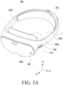
- FIG. 3A is a perspective view illustrating a structure of an electronic device according to an embodiment.
- FIGS. 3B and 3C are perspective views illustrating a structure of an electronic device according to an embodiment.
- camera modules 311, 312, 313, 314, 315, and 316 and/or a depth sensor 317 for obtaining information related to the ambient environment of the electronic device 300 may be disposed on the first surface 301 of the housing.
- the camera modules 311 and 312 may obtain images related to the ambient environment of the electronic device 300.
- the camera modules 313, 314, 315, and 316 may obtain images while the electronic device 300 is worn by the user.
- the camera modules 313, 314, 315, and 316 may be used for hand detection, tracking, and recognition of the user gesture (e.g., hand motion).
- the camera modules 313, 314, 315, and 316 may be used for 3DoF or 6DoF head tracking, location (space or environment) recognition, and/or movement recognition.
- the camera modules 311 and 312 may be used for hand detection and tracking and recognition of the user's gesture.
- the depth sensor 317 may be configured to transmit a signal and receive a signal reflected from an object and be used for identifying the distance to the object, such as time of flight (TOF).
- TOF time of flight
- the camera modules 313, 314, 315, and 316 may identify the distance to the object.
- camera modules 325 and 326 for face recognition and/or a display module 321 (and/or lens) may be disposed on the second surface 302 of the housing of the electronic device 300.
- the display module 321 (and/or lens) of FIG. 3C may be, or may be a part of, the display member 340 of FIG. 3A .
- the face recognition camera modules 325 and 326 adjacent to the display may be used for recognizing the user's face or may recognize and/or track both eyes of the user.
- the display module 321 (and/or lens) may be disposed on the second surface 320 of the electronic device 300.
- the electronic device 300 may not include the camera modules 315 and 316 among the plurality of camera modules 313, 314, 315, and 316.
- the electronic device 300 may not include the camera modules 315 and 316 among the plurality of camera modules 313, 314, 315, and 316.
- the electronic device 300 may further include at least one of the components shown in FIG. 2 .
- the display module 160 may display (e.g., provide) an image (e.g., the icon 410 or an execution screen related to a specified application) in the 3D virtual space 401 (e.g., space of augmented reality, virtual reality, mixed reality, and/or extended reality) through a plurality of displays (e.g., the first display 251 and second display 252 of FIG. 2 , the display member 340 of FIG. 3A , the display module 321 of FIG. 3C ).
- an image e.g., the icon 410 or an execution screen related to a specified application
- 3D virtual space 401 e.g., space of augmented reality, virtual reality, mixed reality, and/or extended reality
- a plurality of displays e.g., the first display 251 and second display 252 of FIG. 2 , the display member 340 of FIG. 3A , the display module 321 of FIG. 3C ).
- the icon 410 may include a plurality of graphical objects (e.g., a plurality of 3D graphical objects) configured in each of a plurality of layers having a depth (e.g., a predetermined distance in the depth direction (z direction), and may be configured as a tile of a minimum size as an image representing an application.
- the icon 410 may be configured to execute the application when a user input (e.g., tap) is received.
- the icon 410 may be displayed to have a sense of space in a virtual space of a 3D environment in a changeable form, and may be displayed not only in a 3D environment but also in a 2D environment.
- the icon 410 is a three-dimensional (3D) icon for a specified application, and may be displayed in the 3D virtual space through a display as a three-dimensional (3D) graphical object generated based on at least in part of a group of graphical objects.
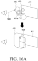
- the graphical objects may include a first graphical object (e.g., world) 411 representing a background area including the content of at least one application and fixed and displayed in the 3D virtual space, a second graphical object (e.g., picto or symbol image) 413 representing at least one application (e.g., a specified application) or one or more contents of at least one application, and a third graphical object (e.g., virtual window) 415 representing a frame area (e.g., outline) directly exposed to the user and configured as a transparent window through which the first graphical object and the second graphical object are shown to the user in the 3D virtual space 401.
- a first graphical object e.g., world
- a second graphical object e.
- the plurality of graphical objects may be displayed in the 3D virtual space 401 while the camera modules (e.g., the camera module 180 of FIG. 1 , the first cameras 211-1 and 211-2 of FIG. 2 , the third camera 213, the camera module 313, 314, 315, and 316 of FIG. 3B ) of the electronic device 200 are spaced apart from each other at a predetermined distance (e.g., with a gap) in the depth direction (e.g., z direction) toward the third graphical object.
- the camera modules e.g., the camera module 180 of FIG. 1 , the first cameras 211-1 and 211-2 of FIG. 2 , the third camera 213, the camera module 313, 314, 315, and 316 of FIG. 3B
- a predetermined distance e.g., with a gap
- the depth direction e.g., z direction
- the first graphical object 411, the second graphical object 413, and the third graphical object 415 may be arranged in a specified arrangement order along the depth direction and displayed in the 3D virtual space, and the arrangement order, shape, size, or display position may be changed based on the state of the application.
- the icon 410 may be configured to be flexibly expandable or shrinkable.
- a form (title) of flexibly expanding the icon 410 may include a quick swipe that is exposed to the task of the application when swiping the icon, as a form (tile) in which the user may use the function of the application quickly with fewer motions, an application notification that exposes the notification of the application when swiping the icon in a state in which an application notification badge is floating as a form (tile) in which may identify the notification of the application quickly with fewer motions, and/or an application widget (e.g., small screen) that is expanded to expose the applicationrelated function when the user expands the icon area by a specific gesture input (e.g., two fingers) as a form (tile) capable of performing an immediate action or detailed information related to the application.
- a specific gesture input e.g., two fingers
- the at least one processor 120 may execute the application and may control the display module 160 (e.g., the first display 251 and the second display 252 of FIG. 1 , the display member 340 of FIG. 3A , the display module 321 of FIG. 3C ) to display the execution screen of the application.
- the at least one processor 120 may obtain state information related to a state change of at least one application or a state change of content included in the application by a user interaction or at least one sensor (e.g., the sensor module 176 of FIG. 1 ).
- the at least one processor 120 may change at least one graphical object among the plurality of graphical objects 411, 413, and 415 to indicate a state change of the at least one application, based on the state information about the at least one application, and may control the display module 160 to display the changed icon 410 reflecting the changed at least one graphical object in the 3D virtual space 401.
- the at least one processor 120 may change the layer order (e.g., arrangement order with respect to the depth direction (z direction)) of the plurality of graphical objects 411, 413, and 415 based on the state information about the at least one application.
- the at least one processor 120 may display an icon 410a configured as a layer in the order of the first graphical object 411, the second graphical object 413, and the third graphical object 415 in the direction toward the user.
- the at least one processor 120 may display an icon 410b in which the second graphical object 413 configured in the layer between the first graphical object 411 and the third graphical object 415 is changed in order (e.g., transition state) to a higher layer of the first graphical object 411.
- the processor 120 sets a layer between the first graphical object 411 and the third graphical object 415.
- An icon 410b obtained by changing the order of the second graphical object 413 to a higher layer of the first graphical object 411 may be displayed.
- the at least one processor 120 may display an icon 410c changed into a form of a content object 501 in which some (e.g., the second graphical object 413 among the plurality of graphical objects) are maintained to have continuity/consistency to expose the content included in at least one application (e.g., display in the virtual space).
- the changed icon 410c is a metaphor icon form (e.g., an icon form including the content object 501 into which the second graphical object 413 has been changed) of the application when the content object 501 included in the application is exposed and may remain in a portion of the execution screen of the application or a partial area of the expanded content while some (e.g., the second graphical object 413) of the plurality of graphical objects are maintained.
- the content object 501 may be an object changed by applying a visual effect (e.g., a graphic effect) to the second graphical object 413.
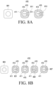
- the at least one processor 120 may apply, to the second graphical object 413 and/or the third graphical object 415, a visual effect that gradually changes the color or brightness according to changes in content information (e.g., resizing according to the number of received messages) or resize the second graphical object 413 and/or the third graphical object 415 in response to a change in content information as in the examples 611 and 612 of the icon 410 based on the content information (e.g., the number of received messages) about a specific application (e.g., messaging or messenger-related application).
- a specific application e.g., messaging or messenger-related application
- FIG. 7 is a view illustrating an example icon to be displayed on an electronic device according to an embodiment.
- the processor 120 may obtain image information using a camera module (e.g., the camera module 180 of FIG. 1 , the camera modules 212-1 and 212-2 of FIG. 2 , the camera modules 325 and 326 of FIG. 3C ) for facial recognition, identify at least one of the eye movement or eyelid movement using the obtained image information, and obtain (e.g., determine or identify) the user's gaze information based on at least one of the identified eye movement or eyelid movement.
- the gaze information may include information related to at least one of gaze fixing, gaze moving, or gaze direction.
- the processor 120 may obtain shape information about the user's eye (e.g., size of the eye obtained based on eyelid movement) based on the obtained image information.
- the specified application indicated by the icon 410 may be executed, and a state change of the icon 410 according to a distance change between the first graphical object 411 and the second graphical object 413 may be displayed based on the execution of the specified application.
- the state change of the icon 410 according to the change in the distance between the first graphical object 411 and the second graphical object 413 according to the state change e.g., an increase or decrease in the number of message receptions
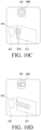
- the electronic device may dynamically change the icon 410 by applying a visual effect (e.g., lighting or outdate) 1003 or 1005 according to the event 1011 to the second graphical object 413, based on the state information of the specified application.
- a visual effect e.g., lighting or outdate
- the electronic device may display an object 1011 indicating the event when there is an active application currently used, as the event affecting the at least one graphical object 411, 413, and 415, and apply a visual effect 1003 to the at least one graphical object 411, 413, and 415 to display the application or lighting brightly.
- the electronic device may display an object 1013 indicating the event when there is an inactive application that may not be currently used, an application requiring an update, or an application running in the background, as the event affecting the at least one graphical object 411, 413, and 415, and apply a visual effect 1005 to the at least one graphical object 411, 413, and 415 to display the application or lighting darkly.
- the electronic device when objects respectively representing a plurality of applications included in the second graphical object are included, based on receiving a first user input, the electronic device according to an embodiment may execute the plurality of applications.
- the electronic device may display the respective execution screens of the plurality of applications in the 3D virtual space and, when displaying the execution screens, dynamically change the icon 410 by applying a visual effect (e.g., displaying a plurality of second graphical objects) 1007 of representing execution of a plurality of applications to the second graphical object when a plurality of applications are running.
- a visual effect e.g., displaying a plurality of second graphical objects
- an electronic device may display an icon 410 including a plurality of graphical objects in a virtual space.
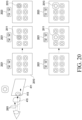
- the electronic device may execute a specified application (e.g., a message or messenger-related application) indicated by the icon 410, maintain display of the icon 410 while the specified application is executed, and display an icon 410 reflecting a visual effect 1111 (e.g., a graphic effect) in which the second graphical object 413 is pressed.
- a specified application e.g., a message or messenger-related application
- the execution screen 1113 may be a screen in which the first graphical object 411 included in the icon 410 is enlarged.
- the user input 1103 may be a different type of user input (e.g., pinch-to-zoom, zoom-in, swipe, or drag) from the first user input 1101.
- the electronic device in response to a user input 1105, may enlarge the execution screen 1113 to overlap and display other execution screens 1114 and 1115 including one or more other contents.
- the electronic device may change (e.g., spread the screens) the states of the execution screens 1114 and 1115 in response to a fourth user input 1107 and may display the changed states.
- the electronic device may shrink the execution screen 1113 by the user's input (e.g., pinch-in or zoom-out) of shrinking the enlarged content and display another execution screen including other functions or other contents as shown in FIGS. 11F to 11I .
- the user's input e.g., pinch-in or zoom-out
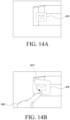
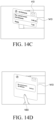
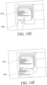
- FIGS. 12A to 12F are views illustrating an example of an operation method in an electronic device according to an embodiment.
- an electronic device may display an icon 410 including a plurality of graphical objects in a virtual space.
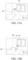
- the electronic device may display an object 1201 corresponding to a movement of the user's hand and display an icon 410 in which a visual effect 1211 indicating a state change of the application is applied to the second graphical object 413.
- the layer order may be changed so that the second graphical object 413 is shown on an upper layer of the first graphical object 411 in response to a first user input (e.g., grab) 1203.
- the electronic device may dynamically display the content icon (e.g., drawing tool or pen) 1205 corresponding to the second graphical object 413 in response to a movement of the object 1201 or a user interaction and execute an input (e.g., drawing) corresponding to the movement of the object 1201 or the user interaction.
- the content icon 1205 may be an icon in which some (e.g., a second graphical object) among the plurality of graphical objects of the icon 410 are changed into a content object form to be maintained and may be displayed in a partial area of the content or a portion of the execution screen of the application so that some of the plurality of graphical objects have consistency/continuity.
Landscapes
- Engineering & Computer Science (AREA)
- General Engineering & Computer Science (AREA)
- Theoretical Computer Science (AREA)
- Human Computer Interaction (AREA)
- Physics & Mathematics (AREA)
- General Physics & Mathematics (AREA)
- User Interface Of Digital Computer (AREA)
Applications Claiming Priority (5)
| Application Number | Priority Date | Filing Date | Title |
|---|---|---|---|
| KR20230021693 | 2023-02-17 | ||
| KR20230043811 | 2023-04-03 | ||
| KR20230061267 | 2023-05-11 | ||
| KR1020230172028A KR20240128554A (ko) | 2023-02-17 | 2023-12-01 | 아이콘을 표시하기 위한 전자 장치, 그 동작 방법과, 비 일시적 저장 매체 |
| PCT/KR2024/095320 WO2024172607A1 (ko) | 2023-02-17 | 2024-02-16 | 아이콘을 표시하기 위한 전자 장치, 그 동작 방법과, 비 일시적 컴퓨터 판독 가능 저장 매체 |
Publications (2)
| Publication Number | Publication Date |
|---|---|
| EP4582921A1 true EP4582921A1 (de) | 2025-07-09 |
| EP4582921A4 EP4582921A4 (de) | 2026-02-25 |
Family
ID=92304101
Family Applications (1)
| Application Number | Title | Priority Date | Filing Date |
|---|---|---|---|
| EP24757324.9A Pending EP4582921A4 (de) | 2023-02-17 | 2024-02-16 | Elektronische vorrichtung zur anzeige eines symbols, verfahren zum betrieb davon und nichttransitorisches computerlesbares speichermedium |
Country Status (3)
| Country | Link |
|---|---|
| US (1) | US20240281110A1 (de) |
| EP (1) | EP4582921A4 (de) |
| CN (1) | CN120641864A (de) |
Families Citing this family (2)
| Publication number | Priority date | Publication date | Assignee | Title |
|---|---|---|---|---|
| CN109274828B (zh) * | 2018-09-30 | 2021-01-15 | 华为技术有限公司 | 一种生成截图的方法、控制方法及电子设备 |
| WO2022208612A1 (ja) * | 2021-03-29 | 2022-10-06 | 京セラ株式会社 | ウェアラブル端末装置、プログラムおよび表示方法 |
Family Cites Families (10)
| Publication number | Priority date | Publication date | Assignee | Title |
|---|---|---|---|---|
| WO2014162762A1 (ja) * | 2013-04-02 | 2014-10-09 | ソニー株式会社 | 情報処理装置、情報処理方法、及びプログラム |
| US11983401B1 (en) * | 2014-06-04 | 2024-05-14 | ULTRAHAPTICS IP TWO LIMITED, , United Kingd | Systems and methods of interacting with a virtual grid in a three-dimensional (3D) sensory space |
| US10437415B2 (en) * | 2015-08-18 | 2019-10-08 | Sony Corporation | System, method, and device for controlling a display |
| US20180095635A1 (en) * | 2016-10-04 | 2018-04-05 | Facebook, Inc. | Controls and Interfaces for User Interactions in Virtual Spaces |
| CA3084149A1 (en) * | 2017-12-22 | 2019-06-27 | Magic Leap, Inc. | Methods and system for managing and displaying virtual content in a mixed reality system |
| US20220229534A1 (en) * | 2020-04-08 | 2022-07-21 | Multinarity Ltd | Coordinating cursor movement between a physical surface and a virtual surface |
| US20230297447A1 (en) * | 2020-06-02 | 2023-09-21 | Maxell, Ltd. | Information processing system, information processing method, and information processing terminal |
| KR20220149191A (ko) * | 2021-04-30 | 2022-11-08 | 삼성전자주식회사 | 손 제스처에 기반하여 기능을 실행하는 전자 장치 및 그 작동 방법 |
| KR102539045B1 (ko) * | 2021-08-06 | 2023-06-02 | 주식회사 피앤씨솔루션 | 착용형 증강현실 장치를 위한 대시보드 제어 장치 및 대시보드 제어 방법 |
| US12548208B2 (en) * | 2022-11-21 | 2026-02-10 | Samsung Electronics Co., Ltd. | Wearable device for displaying visual object for controlling virtual object and method thereof |
-
2024
- 2024-02-16 CN CN202480013172.4A patent/CN120641864A/zh active Pending
- 2024-02-16 EP EP24757324.9A patent/EP4582921A4/de active Pending
- 2024-02-16 US US18/444,234 patent/US20240281110A1/en active Pending
Also Published As
| Publication number | Publication date |
|---|---|
| CN120641864A (zh) | 2025-09-12 |
| US20240281110A1 (en) | 2024-08-22 |
| EP4582921A4 (de) | 2026-02-25 |
Similar Documents
| Publication | Publication Date | Title |
|---|---|---|
| US11914835B2 (en) | Method for displaying user interface and electronic device therefor | |
| JP7674441B2 (ja) | 頭部装着型画像ディスプレイデバイスのための入力を提供するための方法および装置 | |
| US12254234B2 (en) | Apparatus and method for providing contents related to augmented reality service between electronic device and wearable electronic device | |
| EP4390644A1 (de) | Tragbare vorrichtung, die mehrere anwendungsausführungsbildschirme gruppiert und bereitstellt, und verfahren zur steuerung davon | |
| EP4582921A1 (de) | Elektronische vorrichtung zur anzeige eines symbols, verfahren zum betrieb davon und nichttransitorisches computerlesbares speichermedium | |
| US12321526B2 (en) | Wearable electronic device for displaying virtual object and method of controlling the same | |
| US20250384598A1 (en) | Electronic device and method for anchoring of augmented reality object | |
| EP4307157A1 (de) | Elektronische vorrichtung und verfahren zur eingabe von informationen einer elektronischen vorrichtung durch verwendung einer externen elektronischen vorrichtung | |
| KR20230108186A (ko) | 복수의 어플리케이션 실행 화면들을 그룹화하여 제공하는 웨어러블 디바이스 및 그 제어 방법 | |
| EP4325341B1 (de) | Vorrichtung und verfahren zur anzeige eines erweiterten bildschirms einer mobilen vorrichtung | |
| US20230262323A1 (en) | Method and device for obtaining image of object | |
| KR20240128554A (ko) | 아이콘을 표시하기 위한 전자 장치, 그 동작 방법과, 비 일시적 저장 매체 | |
| KR20220162956A (ko) | 영상 통화 중 다양한 커뮤니케이션을 지원하는 전자 장치 및 그의 동작 방법 | |
| US12561933B2 (en) | Wearable device for identifying area for displaying image and method thereof | |
| US20260016951A1 (en) | Electronic device for supporting xr content, and input mode support method therefor | |
| US20250298484A1 (en) | Electronic device and method for identifying user input in virtual space | |
| EP4579396A1 (de) | Durch eine externe vorrichtung gesteuerte vorrichtung für erweiterte realität und verfahren zum betrieb davon | |
| KR20240094948A (ko) | 객체에 대한 정보를 획득하기 위한 전자 장치 및 방법 | |
| KR20240062858A (ko) | 화면의 상태를 변경하기 위한 웨어러블 장치 및 그 방법 | |
| KR20260029952A (ko) | 사용자 입력을 식별하기 위한 전자 장치, 방법, 및 비-일시적 컴퓨터 판독 가능 저장 매체 | |
| KR20250023244A (ko) | 가상 환경에서 객체 선택을 지원하는 방법 및 이를 지원하는 전자 장치 | |
| KR20250026717A (ko) | 가상 현실 공간에서 가상 스크린의 복수의 윈도우들을 관리하기 위한 전자 장치, 방법 및 비 일시적 저장 매체 | |
| KR20230072256A (ko) | 증강 현실 객체의 앵커링을 위한 전자 장치 및 방법 | |
| KR20250015612A (ko) | 객체와 관련된 정보를 공유하는 방법 및 이를 지원하는 웨어러블 전자 장치 | |
| KR20240072880A (ko) | 가상 현실 공간 상에 가상 객체를 제공하기 위한 전자 장치 및 방법 |
Legal Events
| Date | Code | Title | Description |
|---|---|---|---|
| STAA | Information on the status of an ep patent application or granted ep patent |
Free format text: STATUS: THE INTERNATIONAL PUBLICATION HAS BEEN MADE |
|
| PUAI | Public reference made under article 153(3) epc to a published international application that has entered the european phase |
Free format text: ORIGINAL CODE: 0009012 |
|
| STAA | Information on the status of an ep patent application or granted ep patent |
Free format text: STATUS: REQUEST FOR EXAMINATION WAS MADE |
|
| 17P | Request for examination filed |
Effective date: 20250331 |
|
| AK | Designated contracting states |
Kind code of ref document: A1 Designated state(s): AL AT BE BG CH CY CZ DE DK EE ES FI FR GB GR HR HU IE IS IT LI LT LU LV MC ME MK MT NL NO PL PT RO RS SE SI SK SM TR |
|
| A4 | Supplementary search report drawn up and despatched |
Effective date: 20260126 |
|
| RIC1 | Information provided on ipc code assigned before grant |
Ipc: G06F 3/04817 20220101AFI20260120BHEP Ipc: G06F 3/04845 20220101ALI20260120BHEP Ipc: G06F 3/04842 20220101ALI20260120BHEP Ipc: G06F 3/01 20060101ALI20260120BHEP Ipc: G06F 3/0482 20130101ALI20260120BHEP |