EP4583106A2 - Benutzerschnittstellen zur änderung von visuellen medien - Google Patents
Benutzerschnittstellen zur änderung von visuellen medien Download PDFInfo
- Publication number
- EP4583106A2 EP4583106A2 EP25178454.2A EP25178454A EP4583106A2 EP 4583106 A2 EP4583106 A2 EP 4583106A2 EP 25178454 A EP25178454 A EP 25178454A EP 4583106 A2 EP4583106 A2 EP 4583106A2
- Authority
- EP
- European Patent Office
- Prior art keywords
- camera
- computer system
- representation
- video
- view
- Prior art date
- Legal status (The legal status is an assumption and is not a legal conclusion. Google has not performed a legal analysis and makes no representation as to the accuracy of the status listed.)
- Pending
Links
Images







































Classifications
-
- G—PHYSICS
- G11—INFORMATION STORAGE
- G11B—INFORMATION STORAGE BASED ON RELATIVE MOVEMENT BETWEEN RECORD CARRIER AND TRANSDUCER
- G11B27/00—Editing; Indexing; Addressing; Timing or synchronising; Monitoring; Measuring tape travel
- G11B27/10—Indexing; Addressing; Timing or synchronising; Measuring tape travel
- G11B27/19—Indexing; Addressing; Timing or synchronising; Measuring tape travel by using information detectable on the record carrier
- G11B27/28—Indexing; Addressing; Timing or synchronising; Measuring tape travel by using information detectable on the record carrier by using information signals recorded by the same method as the main recording
-
- G—PHYSICS
- G06—COMPUTING OR CALCULATING; COUNTING
- G06T—IMAGE DATA PROCESSING OR GENERATION, IN GENERAL
- G06T3/00—Geometric image transformations in the plane of the image
- G06T3/40—Scaling of whole images or parts thereof, e.g. expanding or contracting
-
- G—PHYSICS
- G11—INFORMATION STORAGE
- G11B—INFORMATION STORAGE BASED ON RELATIVE MOVEMENT BETWEEN RECORD CARRIER AND TRANSDUCER
- G11B27/00—Editing; Indexing; Addressing; Timing or synchronising; Monitoring; Measuring tape travel
- G11B27/02—Editing, e.g. varying the order of information signals recorded on, or reproduced from, record carriers
- G11B27/031—Electronic editing of digitised analogue information signals, e.g. audio or video signals
-
- G—PHYSICS
- G11—INFORMATION STORAGE
- G11B—INFORMATION STORAGE BASED ON RELATIVE MOVEMENT BETWEEN RECORD CARRIER AND TRANSDUCER
- G11B27/00—Editing; Indexing; Addressing; Timing or synchronising; Monitoring; Measuring tape travel
- G11B27/10—Indexing; Addressing; Timing or synchronising; Measuring tape travel
- G11B27/102—Programmed access in sequence to addressed parts of tracks of operating record carriers
-
- G—PHYSICS
- G11—INFORMATION STORAGE
- G11B—INFORMATION STORAGE BASED ON RELATIVE MOVEMENT BETWEEN RECORD CARRIER AND TRANSDUCER
- G11B27/00—Editing; Indexing; Addressing; Timing or synchronising; Monitoring; Measuring tape travel
- G11B27/10—Indexing; Addressing; Timing or synchronising; Measuring tape travel
- G11B27/34—Indicating arrangements
-
- H—ELECTRICITY
- H04—ELECTRIC COMMUNICATION TECHNIQUE
- H04N—PICTORIAL COMMUNICATION, e.g. TELEVISION
- H04N23/00—Cameras or camera modules comprising electronic image sensors; Control thereof
- H04N23/60—Control of cameras or camera modules
- H04N23/62—Control of parameters via user interfaces
-
- H—ELECTRICITY
- H04—ELECTRIC COMMUNICATION TECHNIQUE
- H04N—PICTORIAL COMMUNICATION, e.g. TELEVISION
- H04N23/00—Cameras or camera modules comprising electronic image sensors; Control thereof
- H04N23/60—Control of cameras or camera modules
- H04N23/63—Control of cameras or camera modules by using electronic viewfinders
-
- H—ELECTRICITY
- H04—ELECTRIC COMMUNICATION TECHNIQUE
- H04N—PICTORIAL COMMUNICATION, e.g. TELEVISION
- H04N23/00—Cameras or camera modules comprising electronic image sensors; Control thereof
- H04N23/60—Control of cameras or camera modules
- H04N23/63—Control of cameras or camera modules by using electronic viewfinders
- H04N23/631—Graphical user interfaces [GUI] specially adapted for controlling image capture or setting capture parameters
-
- H—ELECTRICITY
- H04—ELECTRIC COMMUNICATION TECHNIQUE
- H04N—PICTORIAL COMMUNICATION, e.g. TELEVISION
- H04N23/00—Cameras or camera modules comprising electronic image sensors; Control thereof
- H04N23/90—Arrangement of cameras or camera modules, e.g. multiple cameras in TV studios or sports stadiums
-
- H—ELECTRICITY
- H04—ELECTRIC COMMUNICATION TECHNIQUE
- H04N—PICTORIAL COMMUNICATION, e.g. TELEVISION
- H04N23/00—Cameras or camera modules comprising electronic image sensors; Control thereof
- H04N23/95—Computational photography systems, e.g. light-field imaging systems
- H04N23/958—Computational photography systems, e.g. light-field imaging systems for extended depth of field imaging
-
- H—ELECTRICITY
- H04—ELECTRIC COMMUNICATION TECHNIQUE
- H04N—PICTORIAL COMMUNICATION, e.g. TELEVISION
- H04N23/00—Cameras or camera modules comprising electronic image sensors; Control thereof
- H04N23/95—Computational photography systems, e.g. light-field imaging systems
- H04N23/958—Computational photography systems, e.g. light-field imaging systems for extended depth of field imaging
- H04N23/959—Computational photography systems, e.g. light-field imaging systems for extended depth of field imaging by adjusting depth of field during image capture, e.g. maximising or setting range based on scene characteristics
-
- H—ELECTRICITY
- H04—ELECTRIC COMMUNICATION TECHNIQUE
- H04N—PICTORIAL COMMUNICATION, e.g. TELEVISION
- H04N5/00—Details of television systems
- H04N5/222—Studio circuitry; Studio devices; Studio equipment
- H04N5/262—Studio circuits, e.g. for mixing, switching-over, change of character of image, other special effects ; Cameras specially adapted for the electronic generation of special effects
-
- H—ELECTRICITY
- H04—ELECTRIC COMMUNICATION TECHNIQUE
- H04N—PICTORIAL COMMUNICATION, e.g. TELEVISION
- H04N23/00—Cameras or camera modules comprising electronic image sensors; Control thereof
- H04N23/45—Cameras or camera modules comprising electronic image sensors; Control thereof for generating image signals from two or more image sensors being of different type or operating in different modes, e.g. with a CMOS sensor for moving images in combination with a charge-coupled device [CCD] for still images
-
- H—ELECTRICITY
- H04—ELECTRIC COMMUNICATION TECHNIQUE
- H04N—PICTORIAL COMMUNICATION, e.g. TELEVISION
- H04N23/00—Cameras or camera modules comprising electronic image sensors; Control thereof
- H04N23/60—Control of cameras or camera modules
- H04N23/67—Focus control based on electronic image sensor signals
-
- H—ELECTRICITY
- H04—ELECTRIC COMMUNICATION TECHNIQUE
- H04N—PICTORIAL COMMUNICATION, e.g. TELEVISION
- H04N23/00—Cameras or camera modules comprising electronic image sensors; Control thereof
- H04N23/60—Control of cameras or camera modules
- H04N23/69—Control of means for changing angle of the field of view, e.g. optical zoom objectives or electronic zooming
-
- H—ELECTRICITY
- H04—ELECTRIC COMMUNICATION TECHNIQUE
- H04N—PICTORIAL COMMUNICATION, e.g. TELEVISION
- H04N5/00—Details of television systems
- H04N5/222—Studio circuitry; Studio devices; Studio equipment
- H04N5/262—Studio circuits, e.g. for mixing, switching-over, change of character of image, other special effects ; Cameras specially adapted for the electronic generation of special effects
- H04N5/272—Means for inserting a foreground image in a background image, i.e. inlay, outlay
Definitions
- the present disclosure relates generally to computer user interfaces and related techniques, and more specifically to user interfaces and techniques for altering visual media.
- Some techniques for altering visual information using computer systems and other electronic devices are generally cumbersome and inefficient. For example, some existing techniques use a complex and time-consuming user interface, which may include multiple key presses or keystrokes. Existing techniques require more time than necessary, wasting user time and device energy. This latter consideration is particularly important in battery-operated devices.
- the present technique provides electronic devices with faster, more efficient methods and interfaces for altering visual content, including applying a synthetic depth-of-field effect to the visual content to emphasize portions of media.
- Such methods and interfaces optionally complement or replace other methods for altering visual content.
- Such methods and interfaces reduce the cognitive burden on a user and produce a more efficient human-machine interface.
- For battery-operated computing devices, such methods and interfaces conserve power and increase the time between battery charges.
- a method performed at a computer system that is in communication with one or more cameras and one or more input devices comprises: detecting, via the one or more input devices, a request to capture a video representative of a field-of-view of the one or more cameras; in response to detecting the request to capture the video: capturing the video over a first capture duration, where the video includes a plurality of frames that are captured over the first capture duration, where the plurality of frames represent a first subject in the field-of-view of the one or more cameras and a second subject in the field-of-view of the one or more cameras, and where, in the plurality of frames, the first subject is moving relative to the field-of-view of the one or more cameras over the first capture duration; applying, to the plurality of frames of the video, a synthetic depth-of-field effect that alters visual information captured by the one or more cameras to emphasize the first subject in the plurality of frames of the video relative to the second subject in the plurality of frames of the video
- a computer program product comprises: one or more programs configured to be executed by one or more processors of a computer system that is in communication with one or more cameras and one or more input devices, the one or more programs including instructions for: detecting, via the one or more input devices, a request to capture a video representative of a field-of-view of the one or more cameras; in response to detecting the request to capture the video: capturing the video over a first capture duration, where the video includes a plurality of frames that are captured over the first capture duration, where the plurality of frames represent a first subject in the field-of-view of the one or more cameras and a second subject in the field-of-view of the one or more cameras, and where, in the plurality of frames, the first subject is moving relative to the field-of-view of the one or more cameras over the first capture duration; applying, to the plurality of frames of the video, a synthetic depth-of-field effect that alters visual information captured by the one or more cameras to
- a transitory computer-readable storage medium stores one or more programs configured to be executed by one or more processors of a computer system that is in communication with one or more cameras, a display generation component, and one or more input devices, the one or more programs including instructions for: displaying, via the display generation component, a user interface that includes: a representation of a video that includes a plurality of frames, the representation including a first subject and a second subject; and a first user interface object indicating that the first subject is being emphasized by a synthetic depth-of-field effect that alters visual information captured by the one or more cameras to emphasize the first subject in the plurality of frames relative to the second subject; while displaying the user interface that includes the representation of the video and the first user interface object, detecting, via the one or more input devices, a gesture that corresponds to selection of the second subject in the representation of the video; and in response to detecting the gesture that corresponds to selection of the second subject in the representation of the representation of the video
- a computer program product comprises: one or more cameras; a display generation component; one or more input devices; one or more processors; and memory storing one or more programs configured to be executed by the one or more processors, the one or more programs including instructions for: displaying, via the display generation component, a user interface that includes: a representation of a video that includes a plurality of frames, the representation including a first subject and a second subject; and a first user interface object indicating that the first subject is being emphasized by a synthetic depth-of-field effect that alters visual information captured by the one or more cameras to emphasize the first subject in the plurality of frames relative to the second subject; while displaying the user interface that includes the representation of the video and the first user interface object, detecting, via the one or more input devices, a gesture that corresponds to selection of the second subject in the representation of the video; and in response to detecting the gesture that corresponds to selection of the second subject in the representation of the video: changing the synthetic depth-of
- a method performed at a computer system that is in communication with a display generation component comprises: displaying, via the display generation component, a user interface that includes concurrently displaying: a representation of a video having a first duration, where the video includes a plurality of changes in subject emphasis in the video, where a change in subject emphasis in the video includes a change in appearance of visual information captured by one or more cameras to emphasize one subject relative to one or more elements in the video, where the plurality of changes include an automatic change in subject emphasis at a first time during the first duration and a user-specified change in subject emphasis at a second time during the first duration that is different from the first time; and a video navigation user interface element for navigating through the video that includes a representation of the first time and a representation of the second time, where: the representation of the second time is visually distinguished from other times in the first duration of the video that do not correspond to changes in subject emphasis; and the representation of the first time is visually distinguished from the representation of the second time.
- a non-transitory computer-readable storage medium stores one or more programs configured to be executed by one or more processors of a computer system that is in communication with a display generation component, the one or more programs including instructions for: displaying, via the display generation component, a user interface that includes concurrently displaying: a representation of a video having a first duration, where the video includes a plurality of changes in subject emphasis in the video, where a change in subject emphasis in the video includes a change in appearance of visual information captured by one or more cameras to emphasize one subject relative to one or more elements in the video, where the plurality of changes include an automatic change in subject emphasis at a first time during the first duration and a user-specified change in subject emphasis at a second time during the first duration that is different from the first time; and a video navigation user interface element for navigating through the video that includes a representation of the first time and a representation of the second time, where: the representation of the second time is visually
- a transitory computer-readable storage medium stores one or more programs configured to be executed by one or more processors of a computer system that is in communication with a display generation component, the one or more programs including instructions for: displaying, via the display generation component, a user interface that includes concurrently displaying: a representation of a video having a first duration, where the video includes a plurality of changes in subject emphasis in the video, where a change in subject emphasis in the video includes a change in appearance of visual information captured by one or more cameras to emphasize one subject relative to one or more elements in the video, where the plurality of changes include an automatic change in subject emphasis at a first time during the first duration and a user-specified change in subject emphasis at a second time during the first duration that is different from the first time; and a video navigation user interface element for navigating through the video that includes a representation of the first time and a representation of the second time, where: the representation of the second time is visually distinguished from other times
- a computer system configured to communicate with one or more cameras; a display generation component.
- the computer system comprises: one or more processors; and memory storing one or more programs configured to be executed by the one or more processors, the one or more programs including instructions for: displaying, via the display generation component, a user interface that includes concurrently displaying: a representation of a video having a first duration, where the video includes a plurality of changes in subject emphasis in the video, where a change in subject emphasis in the video includes a change in appearance of visual information captured by one or more cameras to emphasize one subject relative to one or more elements in the video, where the plurality of changes include an automatic change in subject emphasis at a first time during the first duration and a user-specified change in subject emphasis at a second time during the first duration that is different from the first time; and a video navigation user interface element for navigating through the video that includes a representation of the first time and a representation of the second time, where: the representation of the second time is visually
- a computer system configured to communicate with one or more cameras; a display generation component.
- the computer system comprises: means for displaying, via the display generation component, a user interface that includes: displaying, via the display generation component, a user interface that includes concurrently displaying: a representation of a video having a first duration, where the video includes a plurality of changes in subject emphasis in the video, where a change in subject emphasis in the video includes a change in appearance of visual information captured by one or more cameras to emphasize one subject relative to one or more elements in the video, where the plurality of changes include an automatic change in subject emphasis at a first time during the first duration and a user-specified change in subject emphasis at a second time during the first duration that is different from the first time; and a video navigation user interface element for navigating through the video that includes a representation of the first time and a representation of the second time, where: the representation of the second time is visually distinguished from other times in the first duration of the video that do not correspond to changes
- a computer program product comprises: a display generation component; one or more processors; memory storing one or more programs configured to be executed by the one or more processors, the one or more programs including instructions for: displaying, via the display generation component, a user interface that includes concurrently displaying: a representation of a video having a first duration, where the video includes a plurality of changes in subject emphasis in the video, where a change in subject emphasis in the video includes a change in appearance of visual information captured by one or more cameras to emphasize one subject relative to one or more elements in the video, where the plurality of changes include an automatic change in subject emphasis at a first time during the first duration and a user-specified change in subject emphasis at a second time during the first duration that is different from the first time; and a video navigation user interface element for navigating through the video that includes a representation of the first time and a representation of the second time, where: the representation of the second time is visually distinguished from other times in the first duration of the video that
- a method performed at a computer system that is in communication with a display generation component and a plurality of cameras that includes a first camera with first image capture parameters determined by hardware of the first camera and a second camera with second image capture parameters determined by hardware of the second camera, wherein the second image capture parameters are different than the first image capture parameters, is described.
- a non-transitory computer-readable storage medium stores one or more programs configured to be executed by one or more processors of a computer system that is in communication with a display generation component and a plurality of cameras that includes a first camera with first image capture parameters determined by hardware of the first camera and a second camera with second image capture parameters determined by hardware of the second camera, wherein the second image capture parameters are different than the first image capture parameters, the one or more programs including instructions for: displaying, via the display generation component, a camera user interface that includes a representation of a field-of-view of one or more of the plurality of cameras, wherein the representation of the field-of-view is displayed using visual information collected by the first camera with the first image capture parameters; while displaying the representation of the field-of-view using the visual information collected by the first camera, detecting a decrease in distance between a camera location that corresponds to at least one of the plurality of cameras and a focal point location that correspond to
- a transitory computer-readable storage medium stores one or more programs configured to be executed by one or more processors of a computer system that is in communication with a display generation component and a plurality of cameras that includes a first camera with first image capture parameters determined by hardware of the first camera and a second camera with second image capture parameters determined by hardware of the second camera, wherein the second image capture parameters are different than the first image capture parameters, the one or more programs including instructions for: displaying, via the display generation component, a camera user interface that includes a representation of a field-of-view of one or more of the plurality of cameras, wherein the representation of the field-of-view is displayed using visual information collected by the first camera with the first image capture parameters; while displaying the representation of the field-of-view using the visual information collected by the first camera, detecting a decrease in distance between a camera location that corresponds to at least one of the plurality of cameras and a focal point location that correspond to a focal point;
- a computer system configured to communicate with a display generation component and a plurality of cameras that includes a first camera with first image capture parameters determined by hardware of the first camera and a second camera with second image capture parameters determined by hardware of the second camera, wherein the second image capture parameters are different than the first image capture parameters.
- the computer system comprises: one or more processors; and memory storing one or more programs configured to be executed by the one or more processors, the one or more programs including instructions for: displaying, via the display generation component, a camera user interface that includes a representation of a field-of-view of one or more of the plurality of cameras, wherein the representation of the field-of-view is displayed using visual information collected by the first camera with the first image capture parameters; while displaying the representation of the field-of-view using the visual information collected by the first camera, detecting a decrease in distance between a camera location that corresponds to at least one of the plurality of cameras and a focal point location that correspond to a focal point; and in response to detecting the decrease in distance between the camera location and the focal point location: in accordance with a determination that the decreased distance between the camera location and the focal point location is closer than a predetermined threshold distance, transitioning from using the visual information collected by the first camera to display the representation of the field-of-view to using visual information collected by the second camera to display the representation of
- a computer system configured to communicate with a display generation component and a plurality of cameras that includes a first camera with first image capture parameters determined by hardware of the first camera and a second camera with second image capture parameters determined by hardware of the second camera, wherein the second image capture parameters are different than the first image capture parameters, is described.
- the computer system comprises: means for displaying, via the display generation component, a camera user interface that includes a representation of a field-of-view of one or more of the plurality of cameras, wherein the representation of the field-of-view is displayed using visual information collected by the first camera with the first image capture parameters; means, while displaying the representation of the field-of-view using the visual information collected by the first camera, for detecting a decrease in distance between a camera location that corresponds to at least one of the plurality of cameras and a focal point location that correspond to a focal point; and means, responsive to detecting the decrease in distance between the camera location and the focal point location, for: in accordance with a determination that the decreased distance between the camera location and the focal point location is closer than a predetermined threshold distance, transitioning from using the visual information collected by the first camera to display the representation of the field-of-view to using visual information collected by the second camera to display the representation of the field-of-view.
- a computer program product comprises one or more programs configured to be executed by one or more processors of a computer system that is in communication with a display generation component and a plurality of cameras that includes a first camera with first image capture parameters determined by hardware of the first camera and a second camera with second image capture parameters determined by hardware of the second camera, wherein the second image capture parameters are different than the first image capture parameters.
- the one or more programs include instructions for: displaying, via the display generation component, a camera user interface that includes a representation of a field-of-view of one or more of the plurality of cameras, wherein the representation of the field-of-view is displayed using visual information collected by the first camera with the first image capture parameters; while displaying the representation of the field-of-view using the visual information collected by the first camera, detecting a decrease in distance between a camera location that corresponds to at least one of the plurality of cameras and a focal point location that correspond to a focal point; and in response to detecting the decrease in distance between the camera location and the focal point location: in accordance with a determination that the decreased distance between the camera location and the focal point location is closer than a predetermined threshold distance, transitioning from using the visual information collected by the first camera to display the representation of the field-of-view to using visual information collected by the second camera to display the representation of the field-of-view.
- a method performed at a computer system that is in communication with a display generation component comprises: playing, via the display generation component, a portion of a video that includes a first subject emphasis change that occurs at a first time, wherein the first subject emphasis change includes a change in appearance of visual information captured by one or more cameras to emphasize a respective subject relative to one or more elements in the video during a first period of time that follows the first time; after playing the portion of the video that includes the first subject emphasis change that occurs at the first time, detecting a request to change subject emphasis at a second time in the video that is different from the first time; and in response to detecting the request to change subject emphasis at the second time in the video: changing the subject emphasis in the video during a second period of time that follows the second time; and changing the first subject emphasis change that occurs at the first time including changing the emphasis of the respective subject relative to the one or more elements in the video during the first period of time that follows the first time.
- a non-transitory computer-readable storage medium stores one or more programs configured to be executed by one or more processors of a computer system that is in communication with a display generation component, the one or more programs including instructions for: playing, via the display generation component, a portion of a video that includes a first subject emphasis change that occurs at a first time, wherein the first subject emphasis change includes a change in appearance of visual information captured by one or more cameras to emphasize a respective subject relative to one or more elements in the video during a first period of time that follows the first time; after playing the portion of the video that includes the first subject emphasis change that occurs at the first time, detecting a request to change subject emphasis at a second time in the video that is different from the first time; and in response to detecting the request to change subject emphasis at the second time in the video: changing the subject emphasis in the video during a second period of time that follows the second time; and changing the first subject emphasis change that occurs at the first time including
- a computer system that is configured to communicate with a display generation component.
- the computer system comprises: one or more processors; and memory storing one or more programs configured to be executed by the one or more processors, the one or more programs including instructions for: playing, via the display generation component, a portion of a video that includes a first subject emphasis change that occurs at a first time, wherein the first subject emphasis change includes a change in appearance of visual information captured by one or more cameras to emphasize a respective subject relative to one or more elements in the video during a first period of time that follows the first time; after playing the portion of the video that includes the first subject emphasis change that occurs at the first time, detecting a request to change subject emphasis at a second time in the video that is different from the first time; and in response to detecting the request to change subject emphasis at the second time in the video: changing the subject emphasis in the video during a second period of time that follows the second time; and changing the first subject emphasis change that occurs at the first time including changing the emphasis of the respective subject relative
- a computer system that is configured to communicate with a display generation component and one or more input devices.
- the computer system comprises: means for playing, via the display generation component, a portion of a video that includes a first subject emphasis change that occurs at a first time, wherein the first subject emphasis change includes a change in appearance of visual information captured by one or more cameras to emphasize a respective subject relative to one or more elements in the video during a first period of time that follows the first time; means, after playing the portion of the video that includes the first subject emphasis change that occurs at the first time, for detecting a request to change subject emphasis at a second time in the video that is different from the first time; and means, responsive to detecting the request to change subject emphasis at the second time in the video, for: changing the subject emphasis in the video during a second period of time that follows the second time; and changing the first subject emphasis change that occurs at the first time including changing the emphasis of the respective subject relative to the one or more elements in the video during the first period of time that follows the first time.
- a computer program product comprises one or more programs configured to be executed by one or more processors of a computer system that is in communication with a display generation component.
- the one or more programs include instructions for: playing, via the display generation component, a portion of a video that includes a first subject emphasis change that occurs at a first time, wherein the first subject emphasis change includes a change in appearance of visual information captured by one or more cameras to emphasize a respective subject relative to one or more elements in the video during a first period of time that follows the first time; after playing the portion of the video that includes the first subject emphasis change that occurs at the first time, detecting a request to change subject emphasis at a second time in the video that is different from the first time; and in response to detecting the request to change subject emphasis at the second time in the video: changing the subject emphasis in the video during a second period of time that follows the second time; and changing the first subject emphasis change that occurs at the first time including changing the emphasis of the respective subject relative to the one or more elements
- Executable instructions for performing these functions are, optionally, included in a non-transitory computer-readable storage medium or other computer program product configured for execution by one or more processors. Executable instructions for performing these functions are, optionally, included in a transitory computer-readable storage medium or other computer program product configured for execution by one or more processors.
- electronic devices that provide efficient methods and interfaces altering visual content.
- electronic devices are needed that allow a user to alter visual content by applying a synthetic depth-of-field effect to multiple frames of media without having to manually change and/or blur the frames of the media to mimic a depth-of-field effect.
- Such techniques can reduce the cognitive burden on a user who desires to alter visual content in media, thereby enhancing productivity. Further, such techniques can reduce processor use and battery power otherwise wasted on redundant user inputs.
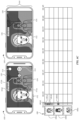
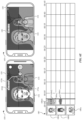
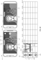
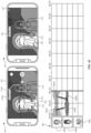
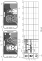
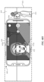
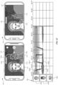
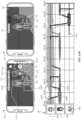
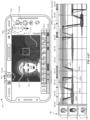
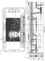
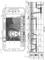
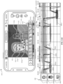
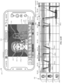
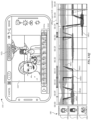
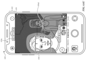
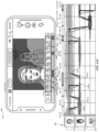
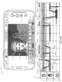
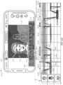
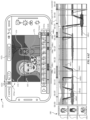
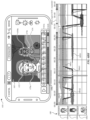
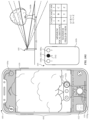
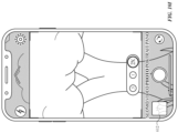
- FIGS. 6A-6BJ are user interfaces for altering visual media using a computer system in accordance with some embodiments.
- FIG. 7 is a flow diagram illustrating methods of altering visual content in accordance with some embodiments.
- FIG. 8 is a flow diagram illustrating methods of altering visual content in accordance with some embodiments.
- FIG. 9 is a flow diagram illustrating methods of altering visual content in accordance with some embodiments.
- FIG. 13 is a flow diagram illustrating methods of altering visual content in accordance with some embodiments.
- the user interfaces in FIGS. 6A-6BJ are used to illustrate the processes described below, including the processes in FIGS. 7 , 8 , 9 , and 13 .
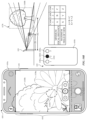
- FIGS. 10A-10I illustrate exemplary user interfaces for managing media capture using a computer system in accordance with some embodiments.
- FIG. 11 is a flow diagram illustrating an exemplary method for managing media capture using a computer system in accordance with some embodiments.
- the user interfaces in FIGS. 10A-10I are used to illustrate the processes described below, including the processes in FIG. 11 .
- the processes described below enhance the operability of the devices and make the user-device interfaces more efficient (e.g., by helping the user to provide proper inputs and reducing user mistakes when operating/interacting with the device) through various techniques, including by providing improved visual feedback to the user, reducing the number of inputs needed to perform an operation, providing additional control options without cluttering the user interface with additional displayed controls, performing an operation when a set of conditions has been met without requiring further user input, and/or additional techniques. These techniques also reduce power usage and improve battery life of the device by enabling the user to use the device more quickly and efficiently.
- system or computer readable medium contains instructions for performing the contingent operations based on the satisfaction of the corresponding one or more conditions and thus is capable of determining whether the contingency has or has not been satisfied without explicitly repeating steps of a method until all of the conditions upon which steps in the method are contingent have been met.
- a system or computer readable storage medium can repeat the steps of a method as many times as are needed to ensure that all of the contingent steps have been performed.
- first means "first,” “second,” etc. to describe various elements, these elements should not be limited by the terms. These terms are only used to distinguish one element from another.
- a first touch could be termed a second touch, and, similarly, a second touch could be termed a first touch, without departing from the scope of the various described embodiments.
- the first touch and the second touch are both touches, but they are not the same touch.
- if is, optionally, construed to mean “when” or “upon” or “in response to determining” or “in response to detecting,” depending on the context.
- phrase “if it is determined” or “if [a stated condition or event] is detected” is, optionally, construed to mean “upon determining” or “in response to determining” or “upon detecting [the stated condition or event]” or “in response to detecting [the stated condition or event],” depending on the context.
- the device is a portable communications device, such as a mobile telephone, that also contains other functions, such as PDA and/or music player functions.
- portable multifunction devices include, without limitation, the iPhone ® , iPod Touch ® , and iPad ® devices from Apple Inc. of Cupertino, California.
- Other portable electronic devices such as laptops or tablet computers with touch-sensitive surfaces (e.g., touch screen displays and/or touchpads), are, optionally, used.
- the device is not a portable communications device, but is a desktop computer with a touch-sensitive surface (e.g., a touch screen display and/or a touchpad).
- the electronic device is a computer system that is in communication (e.g., via wireless communication, via wired communication) with a display generation component.
- the display generation component is configured to provide visual output, such as display via a CRT display, display via an LED display, or display via image projection.
- the display generation component is integrated with the computer system. In some embodiments, the display generation component is separate from the computer system.
- displaying includes causing to display the content (e.g., video data rendered or decoded by display controller 156) by transmitting, via a wired or wireless connection, data (e.g., image data or video data) to an integrated or external display generation component to visually produce the content.
- content e.g., video data rendered or decoded by display controller 1566
- data e.g., image data or video data
- an electronic device that includes a display and a touch-sensitive surface is described. It should be understood, however, that the electronic device optionally includes one or more other physical user-interface devices, such as a physical keyboard, a mouse, and/or a joystick.
- the device typically supports a variety of applications, such as one or more of the following: a drawing application, a presentation application, a word processing application, a website creation application, a disk authoring application, a spreadsheet application, a gaming application, a telephone application, a video conferencing application, an e-mail application, an instant messaging application, a workout support application, a photo management application, a digital camera application, a digital video camera application, a web browsing application, a digital music player application, and/or a digital video player application.
- applications such as one or more of the following: a drawing application, a presentation application, a word processing application, a website creation application, a disk authoring application, a spreadsheet application, a gaming application, a telephone application, a video conferencing application, an e-mail application, an instant messaging application, a workout support application, a photo management application, a digital camera application, a digital video camera application, a web browsing application, a digital music player application, and/or a digital video player application.
- the various applications that are executed on the device optionally use at least one common physical user-interface device, such as the touch-sensitive surface.
- One or more functions of the touch-sensitive surface as well as corresponding information displayed on the device are, optionally, adjusted and/or varied from one application to the next and/or within a respective application.
- a common physical architecture (such as the touch-sensitive surface) of the device optionally supports the variety of applications with user interfaces that are intuitive and transparent to the user.
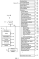
- FIG. 1A is a block diagram illustrating portable multifunction device 100 with touch-sensitive display system 112 in accordance with some embodiments.
- Touch-sensitive display 112 is sometimes called a "touch screen” for convenience and is sometimes known as or called a "touch-sensitive display system.”
- Device 100 includes memory 102 (which optionally includes one or more computer-readable storage mediums), memory controller 122, one or more processing units (CPUs) 120, peripherals interface 118, RF circuitry 108, audio circuitry 110, speaker 111, microphone 113, input/output (I/O) subsystem 106, other input control devices 116, and external port 124.
- Device 100 optionally includes one or more optical sensors 164.
- Device 100 optionally includes one or more contact intensity sensors 165 for detecting intensity of contacts on device 100 (e.g., a touch-sensitive surface such as touch-sensitive display system 112 of device 100).
- Device 100 optionally includes one or more tactile output generators 167 for generating tactile outputs on device 100 (e.g., generating tactile outputs on a touch-sensitive surface such as touch-sensitive display system 112 of device 100 or touchpad 355 of device 300). These components optionally communicate over one or more communication buses or signal lines 103.
- the term "intensity" of a contact on a touch-sensitive surface refers to the force or pressure (force per unit area) of a contact (e.g., a finger contact) on the touch-sensitive surface, or to a substitute (proxy) for the force or pressure of a contact on the touch-sensitive surface.
- the intensity of a contact has a range of values that includes at least four distinct values and more typically includes hundreds of distinct values (e.g., at least 256).
- Intensity of a contact is, optionally, determined (or measured) using various approaches and various sensors or combinations of sensors. For example, one or more force sensors underneath or adjacent to the touch-sensitive surface are, optionally, used to measure force at various points on the touch-sensitive surface.
- force measurements from multiple force sensors are combined (e.g., a weighted average) to determine an estimated force of a contact.
- a pressure-sensitive tip of a stylus is, optionally, used to determine a pressure of the stylus on the touch-sensitive surface.
- the size of the contact area detected on the touch-sensitive surface and/or changes thereto, the capacitance of the touch-sensitive surface proximate to the contact and/or changes thereto, and/or the resistance of the touch-sensitive surface proximate to the contact and/or changes thereto are, optionally, used as a substitute for the force or pressure of the contact on the touch-sensitive surface.
- the substitute measurements for contact force or pressure are used directly to determine whether an intensity threshold has been exceeded (e.g., the intensity threshold is described in units corresponding to the substitute measurements).
- the substitute measurements for contact force or pressure are converted to an estimated force or pressure, and the estimated force or pressure is used to determine whether an intensity threshold has been exceeded (e.g., the intensity threshold is a pressure threshold measured in units of pressure).
- intensity of a contact as an attribute of a user input allows for user access to additional device functionality that may otherwise not be accessible by the user on a reduced-size device with limited real estate for displaying affordances (e.g., on a touch-sensitive display) and/or receiving user input (e.g., via a touch-sensitive display, a touch-sensitive surface, or a physical/mechanical control such as a knob or a button).
- the term "tactile output” refers to physical displacement of a device relative to a previous position of the device, physical displacement of a component (e.g., a touch-sensitive surface) of a device relative to another component (e.g., housing) of the device, or displacement of the component relative to a center of mass of the device that will be detected by a user with the user's sense of touch.
- a component e.g., a touch-sensitive surface
- another component e.g., housing
- the tactile output generated by the physical displacement will be interpreted by the user as a tactile sensation corresponding to a perceived change in physical characteristics of the device or the component of the device.
- a touch-sensitive surface e.g., a touch-sensitive display or trackpad
- movement of a touch-sensitive surface is, optionally, interpreted by the user as a "down click" or "up click" of a physical actuator button.
- a user will feel a tactile sensation such as an "down click” or “up click” even when there is no movement of a physical actuator button associated with the touch-sensitive surface that is physically pressed (e.g., displaced) by the user's movements.
- movement of the touch-sensitive surface is, optionally, interpreted or sensed by the user as "roughness" of the touch-sensitive surface, even when there is no change in smoothness of the touch-sensitive surface. While such interpretations of touch by a user will be subject to the individualized sensory perceptions of the user, there are many sensory perceptions of touch that are common to a large majority of users.
- a tactile output is described as corresponding to a particular sensory perception of a user (e.g., an "up click,” a “down click,” “roughness")
- the generated tactile output corresponds to physical displacement of the device or a component thereof that will generate the described sensory perception for a typical (or average) user.
- device 100 is only one example of a portable multifunction device, and that device 100 optionally has more or fewer components than shown, optionally combines two or more components, or optionally has a different configuration or arrangement of the components.
- the various components shown in FIG. 1A are implemented in hardware, software, or a combination of both hardware and software, including one or more signal processing and/or application-specific integrated circuits.
- Memory 102 optionally includes high-speed random access memory and optionally also includes non-volatile memory, such as one or more magnetic disk storage devices, flash memory devices, or other non-volatile solid-state memory devices.
- Memory controller 122 optionally controls access to memory 102 by other components of device 100.
- Peripherals interface 118 can be used to couple input and output peripherals of the device to CPU 120 and memory 102.
- the one or more processors 120 run or execute various software programs (such as computer programs (e.g., including instructions)) and/or sets of instructions stored in memory 102 to perform various functions for device 100 and to process data.
- peripherals interface 118, CPU 120, and memory controller 122 are, optionally, implemented on a single chip, such as chip 104. In some other embodiments, they are, optionally, implemented on separate chips.
- RF circuitry 108 optionally communicates with networks, such as the Internet, also referred to as the World Wide Web (WWW), an intranet and/or a wireless network, such as a cellular telephone network, a wireless local area network (LAN) and/or a metropolitan area network (MAN), and other devices by wireless communication.
- the RF circuitry 108 optionally includes well-known circuitry for detecting near field communication (NFC) fields, such as by a short-range communication radio.
- NFC near field communication
- Audio circuitry 110, speaker 111, and microphone 113 provide an audio interface between a user and device 100.
- Audio circuitry 110 receives audio data from peripherals interface 118, converts the audio data to an electrical signal, and transmits the electrical signal to speaker 111.
- Speaker 111 converts the electrical signal to human-audible sound waves.
- Audio circuitry 110 also receives electrical signals converted by microphone 113 from sound waves.
- Audio circuitry 110 converts the electrical signal to audio data and transmits the audio data to peripherals interface 118 for processing. Audio data is, optionally, retrieved from and/or transmitted to memory 102 and/or RF circuitry 108 by peripherals interface 118.
- audio circuitry 110 also includes a headset jack (e.g., 212, FIG. 2 ). The headset jack provides an interface between audio circuitry 110 and removable audio input/output peripherals, such as output-only headphones or a headset with both output (e.g., a headphone for one or both ears) and input (e.g., a microphone
- I/O subsystem 106 couples input/output peripherals on device 100, such as touch screen 112 and other input control devices 116, to peripherals interface 118.
- I/O subsystem 106 optionally includes display controller 156, optical sensor controller 158, depth camera controller 169, intensity sensor controller 159, haptic feedback controller 161, and one or more input controllers 160 for other input or control devices.
- the one or more input controllers 160 receive/send electrical signals from/to other input control devices 116.
- the other input control devices 116 optionally include physical buttons (e.g., push buttons, rocker buttons, etc.), dials, slider switches, joysticks, click wheels, and so forth.
- input controller(s) 160 are, optionally, coupled to any (or none) of the following: a keyboard, an infrared port, a USB port, and a pointer device such as a mouse.
- the one or more buttons optionally include an up/down button for volume control of speaker 111 and/or microphone 113.
- the one or more buttons optionally include a push button (e.g., 206, FIG. 2 ).
- the electronic device is a computer system that is in communication (e.g., via wireless communication, via wired communication) with one or more input devices.
- the one or more input devices include a touch-sensitive surface (e.g., a trackpad, as part of a touch-sensitive display).
- the one or more input devices include one or more camera sensors (e.g., one or more optical sensors 164 and/or one or more depth camera sensors 175), such as for tracking a user's gestures (e.g., hand gestures) and/or air gestures) as input.
- the one or more input devices are integrated with the computer system. In some embodiments, the one or more input devices are separate from the computer system.
- an air gesture is a gesture that is detected without the user touching an input element that is part of the device (or independently of an input element that is a part of the device) and is based on detected motion of a portion of the user's body through the air including motion of the user's body relative to an absolute reference (e.g., an angle of the user's arm relative to the ground or a distance of the user's hand relative to the ground), relative to another portion of the user's body (e.g., movement of a hand of the user relative to a shoulder of the user, movement of one hand of the user relative to another hand of the user, and/or movement of a finger of the user relative to another finger or portion of a hand of the user), and/or absolute motion of a portion of the user's body (e.g., a tap gesture that includes movement of a hand in a predetermined pose by a predetermined amount and/or speed, or a shake gesture that includes a predetermined speed or amount of rotation of a portion of the user
- a quick press of the push button optionally disengages a lock of touch screen 112 or optionally begins a process that uses gestures on the touch screen to unlock the device, as described in U.S. Patent Application 11/322,549, "Unlocking a Device by Performing Gestures on an Unlock Image," filed December 23, 2005 , U.S. Pat. No. 7,657,849 , which is hereby incorporated by reference in its entirety.
- a longer press of the push button e.g., 206) optionally turns power to device 100 on or off.
- the functionality of one or more of the buttons are, optionally, user-customizable.
- Touch screen 112 is used to implement virtual or soft buttons and one or more soft keyboards.
- Touch-sensitive display 112 provides an input interface and an output interface between the device and a user.
- Display controller 156 receives and/or sends electrical signals from/to touch screen 112.
- Touch screen 112 displays visual output to the user.
- the visual output optionally includes graphics, text, icons, video, and any combination thereof (collectively termed "graphics"). In some embodiments, some or all of the visual output optionally corresponds to user-interface objects.
- Touch screen 112 has a touch-sensitive surface, sensor, or set of sensors that accepts input from the user based on haptic and/or tactile contact.
- Touch screen 112 and display controller 156 (along with any associated modules and/or sets of instructions in memory 102) detect contact (and any movement or breaking of the contact) on touch screen 112 and convert the detected contact into interaction with user-interface objects (e.g., one or more soft keys, icons, web pages, or images) that are displayed on touch screen 112.
- user-interface objects e.g., one or more soft keys, icons, web pages, or images
- a point of contact between touch screen 112 and the user corresponds to a finger of the user.
- Touch screen 112 optionally uses LCD (liquid crystal display) technology, LPD (light emitting polymer display) technology, or LED (light emitting diode) technology, although other display technologies are used in other embodiments.
- Touch screen 112 and display controller 156 optionally detect contact and any movement or breaking thereof using any of a plurality of touch sensing technologies now known or later developed, including but not limited to capacitive, resistive, infrared, and surface acoustic wave technologies, as well as other proximity sensor arrays or other elements for determining one or more points of contact with touch screen 112.
- touch sensing technologies now known or later developed, including but not limited to capacitive, resistive, infrared, and surface acoustic wave technologies, as well as other proximity sensor arrays or other elements for determining one or more points of contact with touch screen 112.
- projected mutual capacitance sensing technology is used, such as that found in the iPhone ® and iPod Touch ® from Apple Inc. of Cupertino, California.
- a touch-sensitive display in some embodiments of touch screen 112 is, optionally, analogous to the multi-touch sensitive touchpads described in the following U.S. Patents: 6,323,846 (Westerman et al. ), 6,570,557 (Westerman et al. ), and/or 6,677,932 (Westerman ), and/or U.S. Patent Publication 2002/0015024A1 , each of which is hereby incorporated by reference in its entirety.
- touch screen 112 displays visual output from device 100, whereas touch-sensitive touchpads do not provide visual output.
- a touch-sensitive display in some embodiments of touch screen 112 is described in the following applications: (1) U.S. Patent Application No. 11/381,313, "Multipoint Touch Surface Controller,” filed May 2, 2006 ; (2) U.S. Patent Application No. 10/840,862, “Multipoint Touchscreen,” filed May 6, 2004 ; (3) U.S. Patent Application No. 10/903,964, "Gestures For Touch Sensitive Input Devices," filed July 30, 2004 ; (4) U.S. Patent Application No. 11/048,264, “Gestures For Touch Sensitive Input Devices,” filed January 31, 2005 ; (5) U.S. Patent Application No.
- Touch screen 112 optionally has a video resolution in excess of 100 dpi. In some embodiments, the touch screen has a video resolution of approximately 160 dpi.
- the user optionally makes contact with touch screen 112 using any suitable object or appendage, such as a stylus, a finger, and so forth.
- the user interface is designed to work primarily with finger-based contacts and gestures, which can be less precise than stylus-based input due to the larger area of contact of a finger on the touch screen.
- the device translates the rough finger-based input into a precise pointer/cursor position or command for performing the actions desired by the user.
- Contact/motion module 130 optionally detects contact with touch screen 112 (in conjunction with display controller 156) and other touch-sensitive devices (e.g., a touchpad or physical click wheel).
- Contact/motion module 130 includes various software components for performing various operations related to detection of contact, such as determining if contact has occurred (e.g., detecting a finger-down event), determining an intensity of the contact (e.g., the force or pressure of the contact or a substitute for the force or pressure of the contact), determining if there is movement of the contact and tracking the movement across the touch-sensitive surface (e.g., detecting one or more finger-dragging events), and determining if the contact has ceased (e.g., detecting a finger-up event or a break in contact).
- Contact/motion module 130 receives contact data from the touch-sensitive surface. Determining movement of the point of contact, which is represented by a series of contact data, optionally includes determining speed (magnitude), velocity (magnitude and direction), and/or an acceleration (a change in magnitude and/or direction) of the point of contact. These operations are, optionally, applied to single contacts (e.g., one finger contacts) or to multiple simultaneous contacts (e.g., "multitouch"/multiple finger contacts). In some embodiments, contact/motion module 130 and display controller 156 detect contact on a touchpad.
- contact/motion module 130 uses a set of one or more intensity thresholds to determine whether an operation has been performed by a user (e.g., to determine whether a user has "clicked" on an icon).
- at least a subset of the intensity thresholds are determined in accordance with software parameters (e.g., the intensity thresholds are not determined by the activation thresholds of particular physical actuators and can be adjusted without changing the physical hardware of device 100). For example, a mouse "click" threshold of a trackpad or touch screen display can be set to any of a large range of predefined threshold values without changing the trackpad or touch screen display hardware.
- Contact/motion module 130 optionally detects a gesture input by a user.
- Different gestures on the touch-sensitive surface have different contact patterns (e.g., different motions, timings, and/or intensities of detected contacts).
- a gesture is, optionally, detected by detecting a particular contact pattern.
- detecting a finger tap gesture includes detecting a finger-down event followed by detecting a finger-up (liftoff) event at the same position (or substantially the same position) as the finger-down event (e.g., at the position of an icon).
- detecting a finger swipe gesture on the touch-sensitive surface includes detecting a finger-down event followed by detecting one or more finger-dragging events, and subsequently followed by detecting a finger-up (liftoff) event.
- Graphics module 132 includes various known software components for rendering and displaying graphics on touch screen 112 or other display, including components for changing the visual impact (e.g., brightness, transparency, saturation, contrast, or other visual property) of graphics that are displayed.
- graphics includes any object that can be displayed to a user, including, without limitation, text, web pages, icons (such as user-interface objects including soft keys), digital images, videos, animations, and the like.
- graphics module 132 stores data representing graphics to be used. Each graphic is, optionally, assigned a corresponding code. Graphics module 132 receives, from applications etc., one or more codes specifying graphics to be displayed along with, if necessary, coordinate data and other graphic property data, and then generates screen image data to output to display controller 156.
- Haptic feedback module 133 includes various software components for generating instructions used by tactile output generator(s) 167 to produce tactile outputs at one or more locations on device 100 in response to user interactions with device 100.
- Text input module 134 which is, optionally, a component of graphics module 132, provides soft keyboards for entering text in various applications (e.g., contacts 137, e-mail 140, IM 141, browser 147, and any other application that needs text input).
- applications e.g., contacts 137, e-mail 140, IM 141, browser 147, and any other application that needs text input).
- GPS module 135 determines the location of the device and provides this information for use in various applications (e.g., to telephone 138 for use in location-based dialing; to camera 143 as picture/video metadata; and to applications that provide location-based services such as weather widgets, local yellow page widgets, and map/navigation widgets).
- applications e.g., to telephone 138 for use in location-based dialing; to camera 143 as picture/video metadata; and to applications that provide location-based services such as weather widgets, local yellow page widgets, and map/navigation widgets).
- Applications 136 optionally include the following modules (or sets of instructions), or a subset or superset thereof:
- contacts module 137 are, optionally, used to manage an address book or contact list (e.g., stored in application internal state 192 of contacts module 137 in memory 102 or memory 370), including: adding name(s) to the address book; deleting name(s) from the address book; associating telephone number(s), e-mail address(es), physical address(es) or other information with a name; associating an image with a name; categorizing and sorting names; providing telephone numbers or e-mail addresses to initiate and/or facilitate communications by telephone 138, video conference module 139, e-mail 140, or IM 141; and so forth.
- an address book or contact list e.g., stored in application internal state 192 of contacts module 137 in memory 102 or memory 370
- telephone module 138 are optionally, used to enter a sequence of characters corresponding to a telephone number, access one or more telephone numbers in contacts module 137, modify a telephone number that has been entered, dial a respective telephone number, conduct a conversation, and disconnect or hang up when the conversation is completed.
- the wireless communication optionally uses any of a plurality of communications standards, protocols, and technologies.
- video conference module 139 includes executable instructions to initiate, conduct, and terminate a video conference between a user and one or more other participants in accordance with user instructions.
- e-mail client module 140 includes executable instructions to create, send, receive, and manage e-mail in response to user instructions.
- e-mail client module 140 makes it very easy to create and send e-mails with still or video images taken with camera module 143.
- workout support module 142 includes executable instructions to create workouts (e.g., with time, distance, and/or calorie burning goals); communicate with workout sensors (sports devices); receive workout sensor data; calibrate sensors used to monitor a workout; select and play music for a workout; and display, store, and transmit workout data.
- create workouts e.g., with time, distance, and/or calorie burning goals
- communicate with workout sensors sports devices
- receive workout sensor data calibrate sensors used to monitor a workout
- select and play music for a workout and display, store, and transmit workout data.
- camera module 143 includes executable instructions to capture still images or video (including a video stream) and store them into memory 102, modify characteristics of a still image or video, or delete a still image or video from memory 102.
- image management module 144 includes executable instructions to arrange, modify (e.g., edit), or otherwise manipulate, label, delete, present (e.g., in a digital slide show or album), and store still and/or video images.
- modify e.g., edit
- present e.g., in a digital slide show or album
- browser module 147 includes executable instructions to browse the Internet in accordance with user instructions, including searching, linking to, receiving, and displaying web pages or portions thereof, as well as attachments and other files linked to web pages.
- calendar module 148 includes executable instructions to create, display, modify, and store calendars and data associated with calendars (e.g., calendar entries, to-do lists, etc.) in accordance with user instructions.
- widget modules 149 are mini-applications that are, optionally, downloaded and used by a user (e.g., weather widget 149-1, stocks widget 149-2, calculator widget 149-3, alarm clock widget 149-4, and dictionary widget 149-5) or created by the user (e.g., user-created widget 149-6).
- a widget includes an HTML (Hypertext Markup Language) file, a CSS (Cascading Style Sheets) file, and a JavaScript file.
- a widget includes an XML (Extensible Markup Language) file and a JavaScript file (e.g., Yahoo! Widgets).
- the widget creator module 150 are, optionally, used by a user to create widgets (e.g., turning a user-specified portion of a web page into a widget).
- search module 151 includes executable instructions to search for text, music, sound, image, video, and/or other files in memory 102 that match one or more search criteria (e.g., one or more user-specified search terms) in accordance with user instructions.
- search criteria e.g., one or more user-specified search terms
- video and music player module 152 includes executable instructions that allow the user to download and play back recorded music and other sound files stored in one or more file formats, such as MP3 or AAC files, and executable instructions to display, present, or otherwise play back videos (e.g., on touch screen 112 or on an external, connected display via external port 124).
- device 100 optionally includes the functionality of an MP3 player, such as an iPod (trademark of Apple Inc.).
- notes module 153 includes executable instructions to create and manage notes, to-do lists, and the like in accordance with user instructions.
- map module 154 are, optionally, used to receive, display, modify, and store maps and data associated with maps (e.g., driving directions, data on stores and other points of interest at or near a particular location, and other location-based data) in accordance with user instructions.
- maps e.g., driving directions, data on stores and other points of interest at or near a particular location, and other location-based data
- device 100 is a device where operation of a predefined set of functions on the device is performed exclusively through a touch screen and/or a touchpad.
- a touch screen and/or a touchpad as the primary input control device for operation of device 100, the number of physical input control devices (such as push buttons, dials, and the like) on device 100 is, optionally, reduced.
- the double tap for example, comprises a first touch (touch begin) on the displayed object for a predetermined phase, a first liftoff (touch end) for a predetermined phase, a second touch (touch begin) on the displayed object for a predetermined phase, and a second liftoff (touch end) for a predetermined phase.
- the definition for event 2 (187-2) is a dragging on a displayed object.
- the dragging for example, comprises a touch (or contact) on the displayed object for a predetermined phase, a movement of the touch across touch-sensitive display 112, and liftoff of the touch (touch end).
- the event also includes information for one or more associated event handlers 190.
- the gesture optionally includes one or more taps, one or more swipes (from left to right, right to left, upward and/or downward), and/or a rolling of a finger (from right to left, left to right, upward and/or downward) that has made contact with device 100.
- inadvertent contact with a graphic does not select the graphic.
- a swipe gesture that sweeps over an application icon optionally does not select the corresponding application when the gesture corresponding to selection is a tap.
- Device 100 optionally also include one or more physical buttons, such as "home" or menu button 204.
- menu button 204 is, optionally, used to navigate to any application 136 in a set of applications that are, optionally, executed on device 100.
- the menu button is implemented as a soft key in a GUI displayed on touch screen 112.
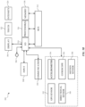
- FIG. 3 is a block diagram of an exemplary multifunction device with a display and a touch-sensitive surface in accordance with some embodiments.
- Device 300 need not be portable.
- device 300 is a laptop computer, a desktop computer, a tablet computer, a multimedia player device, a navigation device, an educational device (such as a child's learning toy), a gaming system, or a control device (e.g., a home or industrial controller).
- Device 300 typically includes one or more processing units (CPUs) 310, one or more network or other communications interfaces 360, memory 370, and one or more communication buses 320 for interconnecting these components.
- Communication buses 320 optionally include circuitry (sometimes called a chipset) that interconnects and controls communications between system components.
- Device 300 includes input/output (I/O) interface 330 comprising display 340, which is typically a touch screen display.
- I/O interface 330 also optionally includes a keyboard and/or mouse (or other pointing device) 350 and touchpad 355, tactile output generator 357 for generating tactile outputs on device 300 (e.g., similar to tactile output generator(s) 167 described above with reference to FIG. 1A ), sensors 359 (e.g., optical, acceleration, proximity, touch-sensitive, and/or contact intensity sensors similar to contact intensity sensor(s) 165 described above with reference to FIG. 1A ).
- sensors 359 e.g., optical, acceleration, proximity, touch-sensitive, and/or contact intensity sensors similar to contact intensity sensor(s) 165 described above with reference to FIG. 1A ).
- Memory 370 includes high-speed random access memory, such as DRAM, SRAM, DDR RAM, or other random access solid state memory devices; and optionally includes non-volatile memory, such as one or more magnetic disk storage devices, optical disk storage devices, flash memory devices, or other non-volatile solid state storage devices. Memory 370 optionally includes one or more storage devices remotely located from CPU(s) 310. In some embodiments, memory 370 stores programs, modules, and data structures analogous to the programs, modules, and data structures stored in memory 102 of portable multifunction device 100 ( FIG. 1A ), or a subset thereof. Furthermore, memory 370 optionally stores additional programs, modules, and data structures not present in memory 102 of portable multifunction device 100.
- memory 370 of device 300 optionally stores drawing module 380, presentation module 382, word processing module 384, website creation module 386, disk authoring module 388, and/or spreadsheet module 390, while memory 102 of portable multifunction device 100 ( FIG. 1A ) optionally does not store these modules.
- Each of the above-identified elements in FIG. 3 is, optionally, stored in one or more of the previously mentioned memory devices.
- Each of the above-identified modules corresponds to a set of instructions for performing a function described above.
- the above-identified modules or computer programs e.g., sets of instructions or including instructions
- memory 370 optionally stores a subset of the modules and data structures identified above.
- memory 370 optionally stores additional modules and data structures not described above.
- FIG. 4A illustrates an exemplary user interface for a menu of applications on portable multifunction device 100 in accordance with some embodiments. Similar user interfaces are, optionally, implemented on device 300.
- user interface 400 includes the following elements, or a subset or superset thereof:
- FIG. 4B illustrates an exemplary user interface on a device (e.g., device 300, FIG. 3 ) with a touch-sensitive surface 451 (e.g., a tablet or touchpad 355, FIG. 3 ) that is separate from the display 450 (e.g., touch screen display 112).
- Device 300 also, optionally, includes one or more contact intensity sensors (e.g., one or more of sensors 359) for detecting intensity of contacts on touch-sensitive surface 451 and/or one or more tactile output generators 357 for generating tactile outputs for a user of device 300.
- one or more contact intensity sensors e.g., one or more of sensors 359
- tactile output generators 357 for generating tactile outputs for a user of device 300.
- the device detects inputs on a touch-sensitive surface that is separate from the display, as shown in FIG. 4B .
- the touch-sensitive surface e.g., 451 in FIG. 4B
- the touch-sensitive surface has a primary axis (e.g., 452 in FIG. 4B ) that corresponds to a primary axis (e.g., 453 in FIG. 4B ) on the display (e.g., 450).
- the device detects contacts (e.g., 460 and 462 in FIG.
- finger inputs e.g., finger contacts, finger tap gestures, finger swipe gestures
- one or more of the finger inputs are replaced with input from another input device (e.g., a mouse-based input or stylus input).
- a swipe gesture is, optionally, replaced with a mouse click (e.g., instead of a contact) followed by movement of the cursor along the path of the swipe (e.g., instead of movement of the contact).
- a tap gesture is, optionally, replaced with a mouse click while the cursor is located over the location of the tap gesture (e.g., instead of detection of the contact followed by ceasing to detect the contact).
- multiple user inputs are simultaneously detected, it should be understood that multiple computer mice are, optionally, used simultaneously, or a mouse and finger contacts are, optionally, used simultaneously.
- FIG. 5A illustrates exemplary personal electronic device 500.
- Device 500 includes body 502.
- device 500 can include some or all of the features described with respect to devices 100 and 300 (e.g., FIGS. 1A-4B ).
- device 500 has touch-sensitive display screen 504, hereafter touch screen 504.
- touch screen 504 optionally includes one or more intensity sensors for detecting intensity of contacts (e.g., touches) being applied.
- the one or more intensity sensors of touch screen 504 (or the touch-sensitive surface) can provide output data that represents the intensity of touches.
- the user interface of device 500 can respond to touches based on their intensity, meaning that touches of different intensities can invoke different user interface operations on device 500.
- device 500 has one or more input mechanisms 506 and 508.
- Input mechanisms 506 and 508, if included, can be physical. Examples of physical input mechanisms include push buttons and rotatable mechanisms.
- device 500 has one or more attachment mechanisms. Such attachment mechanisms, if included, can permit attachment of device 500 with, for example, hats, eyewear, earrings, necklaces, shirts, jackets, bracelets, watch straps, chains, trousers, belts, shoes, purses, backpacks, and so forth. These attachment mechanisms permit device 500 to be worn by a user.
- FIG. 5B depicts exemplary personal electronic device 500.
- device 500 can include some or all of the components described with respect to FIGS. 1A , 1B , and 3 .
- Device 500 has bus 512 that operatively couples I/O section 514 with one or more computer processors 516 and memory 518.
- I/O section 514 can be connected to display 504, which can have touch-sensitive component 522 and, optionally, intensity sensor 524 (e.g., contact intensity sensor).
- I/O section 514 can be connected with communication unit 530 for receiving application and operating system data, using Wi-Fi, Bluetooth, near field communication (NFC), cellular, and/or other wireless communication techniques.
- Device 500 can include input mechanisms 506 and/or 508.
- Input mechanism 506 is, optionally, a rotatable input device or a depressible and rotatable input device, for example.
- Input mechanism 508 is, optionally, a button, in some examples.
- Input mechanism 508 is, optionally, a microphone, in some examples.
- Personal electronic device 500 optionally includes various sensors, such as GPS sensor 532, accelerometer 534, directional sensor 540 (e.g., compass), gyroscope 536, motion sensor 538, and/or a combination thereof, all of which can be operatively connected to I/O section 514.
- sensors such as GPS sensor 532, accelerometer 534, directional sensor 540 (e.g., compass), gyroscope 536, motion sensor 538, and/or a combination thereof, all of which can be operatively connected to I/O section 514.
- Memory 518 of personal electronic device 500 can include one or more non-transitory computer-readable storage mediums, for storing computer-executable instructions, which, when executed by one or more computer processors 516, for example, can cause the computer processors to perform the techniques described below, including processes 700, 800, 900, 1100, and 1300 ( FIGS. 7-9 , 11 , and 13 ).
- a computer-readable storage medium can be any medium that can tangibly contain or store computer-executable instructions for use by or in connection with the instruction execution system, apparatus, or device.
- the storage medium is a transitory computer-readable storage medium.
- the storage medium is a non-transitory computer-readable storage medium.
- the non-transitory computer-readable storage medium can include, but is not limited to, magnetic, optical, and/or semiconductor storages. Examples of such storage include magnetic disks, optical discs based on CD, DVD, or Blu-ray technologies, as well as persistent solid-state memory such as flash, solid-state drives, and the like.
- Personal electronic device 500 is not limited to the components and configuration of FIG. 5B , but can include other or additional components in multiple configurations.
- the term "affordance” refers to a user-interactive graphical user interface object that is, optionally, displayed on the display screen of devices 100, 300, and/or 500 ( FIGS. 1A , 3 , and 5A-5B ).
- an image e.g., icon
- a button e.g., button
- text e.g., hyperlink
- the term "focus selector” refers to an input element that indicates a current part of a user interface with which a user is interacting.
- the cursor acts as a "focus selector” so that when an input (e.g., a press input) is detected on a touch-sensitive surface (e.g., touchpad 355 in FIG. 3 or touch-sensitive surface 451 in FIG. 4B ) while the cursor is over a particular user interface element (e.g., a button, window, slider, or other user interface element), the particular user interface element is adjusted in accordance with the detected input.
- a touch screen display e.g., touch-sensitive display system 112 in FIG.
- a detected contact on the touch screen acts as a "focus selector" so that when an input (e.g., a press input by the contact) is detected on the touch screen display at a location of a particular user interface element (e.g., a button, window, slider, or other user interface element), the particular user interface element is adjusted in accordance with the detected input.
- an input e.g., a press input by the contact
- a particular user interface element e.g., a button, window, slider, or other user interface element
- focus is moved from one region of a user interface to another region of the user interface without corresponding movement of a cursor or movement of a contact on a touch screen display (e.g., by using a tab key or arrow keys to move focus from one button to another button); in these implementations, the focus selector moves in accordance with movement of focus between different regions of the user interface.
- the focus selector is generally the user interface element (or contact on a touch screen display) that is controlled by the user so as to communicate the user's intended interaction with the user interface (e.g., by indicating, to the device, the element of the user interface with which the user is intending to interact).
- a focus selector e.g., a cursor, a contact, or a selection box
- a press input is detected on the touch-sensitive surface (e.g., a touchpad or touch screen) will indicate that the user is intending to activate the respective button (as opposed to other user interface elements shown on a display of the device).
- the term "characteristic intensity" of a contact refers to a characteristic of the contact based on one or more intensities of the contact.
- the characteristic intensity is based on multiple intensity samples.
- the characteristic intensity is, optionally, based on a predefined number of intensity samples, or a set of intensity samples collected during a predetermined time period (e.g., 0.05, 0.1, 0.2, 0.5, 1, 2, 5, 10 seconds) relative to a predefined event (e.g., after detecting the contact, prior to detecting liftoff of the contact, before or after detecting a start of movement of the contact, prior to detecting an end of the contact, before or after detecting an increase in intensity of the contact, and/or before or after detecting a decrease in intensity of the contact).
- a predefined time period e.g., 0.05, 0.1, 0.2, 0.5, 1, 2, 5, 10 seconds
- a characteristic intensity of a contact is, optionally, based on one or more of: a maximum value of the intensities of the contact, a mean value of the intensities of the contact, an average value of the intensities of the contact, a top 10 percentile value of the intensities of the contact, a value at the half maximum of the intensities of the contact, a value at the 90 percent maximum of the intensities of the contact, or the like.
- the duration of the contact is used in determining the characteristic intensity (e.g., when the characteristic intensity is an average of the intensity of the contact over time).
- the characteristic intensity is compared to a set of one or more intensity thresholds to determine whether an operation has been performed by a user.
- the set of one or more intensity thresholds optionally includes a first intensity threshold and a second intensity threshold.
- a contact with a characteristic intensity that does not exceed the first threshold results in a first operation
- a contact with a characteristic intensity that exceeds the first intensity threshold and does not exceed the second intensity threshold results in a second operation
- a contact with a characteristic intensity that exceeds the second threshold results in a third operation.
- a comparison between the characteristic intensity and one or more thresholds is used to determine whether or not to perform one or more operations (e.g., whether to perform a respective operation or forgo performing the respective operation), rather than being used to determine whether to perform a first operation or a second operation.
- a portion of a gesture is identified for purposes of determining a characteristic intensity.
- a touch-sensitive surface optionally receives a continuous swipe contact transitioning from a start location and reaching an end location, at which point the intensity of the contact increases.
- the characteristic intensity of the contact at the end location is, optionally, based on only a portion of the continuous swipe contact, and not the entire swipe contact (e.g., only the portion of the swipe contact at the end location).
- a smoothing algorithm is, optionally, applied to the intensities of the swipe contact prior to determining the characteristic intensity of the contact.
- the smoothing algorithm optionally includes one or more of: an unweighted sliding-average smoothing algorithm, a triangular smoothing algorithm, a median filter smoothing algorithm, and/or an exponential smoothing algorithm.
- these smoothing algorithms eliminate narrow spikes or dips in the intensities of the swipe contact for purposes of determining a characteristic intensity.
- the intensity of a contact on the touch-sensitive surface is, optionally, characterized relative to one or more intensity thresholds, such as a contact-detection intensity threshold, a light press intensity threshold, a deep press intensity threshold, and/or one or more other intensity thresholds.
- the light press intensity threshold corresponds to an intensity at which the device will perform operations typically associated with clicking a button of a physical mouse or a trackpad.
- the deep press intensity threshold corresponds to an intensity at which the device will perform operations that are different from operations typically associated with clicking a button of a physical mouse or a trackpad.
- the device when a contact is detected with a characteristic intensity below the light press intensity threshold (e.g., and above a nominal contact-detection intensity threshold below which the contact is no longer detected), the device will move a focus selector in accordance with movement of the contact on the touch-sensitive surface without performing an operation associated with the light press intensity threshold or the deep press intensity threshold.
- a characteristic intensity below the light press intensity threshold e.g., and above a nominal contact-detection intensity threshold below which the contact is no longer detected
- these intensity thresholds are consistent between different sets of user interface figures.
- An increase of characteristic intensity of the contact from an intensity below the light press intensity threshold to an intensity between the light press intensity threshold and the deep press intensity threshold is sometimes referred to as a "light press” input.
- An increase of characteristic intensity of the contact from an intensity below the deep press intensity threshold to an intensity above the deep press intensity threshold is sometimes referred to as a "deep press” input.
- An increase of characteristic intensity of the contact from an intensity below the contact-detection intensity threshold to an intensity between the contact-detection intensity threshold and the light press intensity threshold is sometimes referred to as detecting the contact on the touch-surface.
- a decrease of characteristic intensity of the contact from an intensity above the contact-detection intensity threshold to an intensity below the contact-detection intensity threshold is sometimes referred to as detecting liftoff of the contact from the touch-surface.
- the contact-detection intensity threshold is zero. In some embodiments, the contact-detection intensity threshold is greater than zero.
- one or more operations are performed in response to detecting a gesture that includes a respective press input or in response to detecting the respective press input performed with a respective contact (or a plurality of contacts), where the respective press input is detected based at least in part on detecting an increase in intensity of the contact (or plurality of contacts) above a press-input intensity threshold.
- the respective operation is performed in response to detecting the increase in intensity of the respective contact above the press-input intensity threshold (e.g., a "down stroke" of the respective press input).
- the press input includes an increase in intensity of the respective contact above the press-input intensity threshold and a subsequent decrease in intensity of the contact below the press-input intensity threshold, and the respective operation is performed in response to detecting the subsequent decrease in intensity of the respective contact below the press-input threshold (e.g., an "up stroke" of the respective press input).
- the device employs intensity hysteresis to avoid accidental inputs sometimes termed "jitter," where the device defines or selects a hysteresis intensity threshold with a predefined relationship to the press-input intensity threshold (e.g., the hysteresis intensity threshold is X intensity units lower than the press-input intensity threshold or the hysteresis intensity threshold is 75%, 90%, or some reasonable proportion of the press-input intensity threshold).
- the hysteresis intensity threshold is X intensity units lower than the press-input intensity threshold or the hysteresis intensity threshold is 75%, 90%, or some reasonable proportion of the press-input intensity threshold.
- the press input includes an increase in intensity of the respective contact above the press-input intensity threshold and a subsequent decrease in intensity of the contact below the hysteresis intensity threshold that corresponds to the press-input intensity threshold, and the respective operation is performed in response to detecting the subsequent decrease in intensity of the respective contact below the hysteresis intensity threshold (e.g., an "up stroke" of the respective press input).
- the press input is detected only when the device detects an increase in intensity of the contact from an intensity at or below the hysteresis intensity threshold to an intensity at or above the press-input intensity threshold and, optionally, a subsequent decrease in intensity of the contact to an intensity at or below the hysteresis intensity, and the respective operation is performed in response to detecting the press input (e.g., the increase in intensity of the contact or the decrease in intensity of the contact, depending on the circumstances).
- UI user interfaces
- portable multifunction device 100 such as portable multifunction device 100, device 300, or device 500.
- FIG. 6A illustrates computer system 600 (e.g., an electronic device) displaying a camera user interface, which includes live preview 630 that optionally extends from the top of the display of computer system 600 to the bottom of the display of computer system 600.
- computer system 600 optionally includes one or more features of device 100, device 300, or device 500.
- computer system 600 is a tablet, phone, laptop, desktop, and/or camera.
- the camera user interface of FIG. 6A includes indicator region 602 and control region 606, which are positioned with respect to live preview 630 such that indicators and controls can be displayed concurrently with live preview 630.
- Camera display region 604 is substantially not overlaid with indicators and/or controls.
- the camera user interface includes visual boundary 608 that indicates the boundary between indicator region 602 and camera display region 604 and the boundary between camera display region 604 and control region 606.
- camera display region 604 includes live preview 630 and zoom controls (e.g., affordances) 622.
- Zoom controls 622 include 0.5x zoom control 622a, 1x zoom control 622b, and 2x zoom control 622c.
- 1x zoom control 622b is enlarged compared to the other zoom controls, which indicates that 1x zoom control 622b is selected and that computer system 600 is displaying live preview 630 at a "1x" zoom level.
- computer system 600 displays 1x zoom control 622b as being selected by displaying 1x zoom control 622b in a different color than the other zoom controls 622.
- control region 606 includes camera mode controls 620, shutter control 610, camera switcher control 614, and a representation of media collection 612.
- camera mode controls 620a-620e are displayed, which includes panoramic mode control 620a, portrait mode control 620b, photo mode control 620c, video mode control 620d, and cinematic video mode control 620e.
- photo mode control 620c is selected, which is indicated by photo mode control 620c being bolded.
- computer system 600 initiates capture of (e.g., and/or captures) photo media (e.g., a still photo) in response to computer system 600 detecting an input directed to shutter control 610.
- 6A is a representation of media (e.g., an image, a video) that was most recently captured by computer system 600.
- computer system 600 in response to detecting an input directed to media collection 612, displays a similar user interface to the user interface illustrated in FIG. 7 (discussed below).
- indicator region 602 is overlaid onto live preview 630 and, optionally, includes a colored (e.g., gray; translucent) overlay.
- FIGS. 6A-6BJ illustrate exemplary user interfaces for altering visual content in accordance with some embodiments.
- FIGS. 6A-6AC illustrate an exemplary embodiment where a synthetic (e.g., simulated, computer-generated) depth-of-field effect is applied to visual content of media that is currently being captured.
- the synthetic depth-of-field effect is applied automatically (e.g., not in response to one or more inputs) and/or in response to a user input.
- computer system 600 makes one or more determinations based on a set of criteria to determine how the synthetic depth-of-field effect is applied and applies the synthetic depth-of-field effect (e.g., without detecting an input to apply the synthetic depth-of-field effect).
- computer system 600 detects an input and applies the synthetic depth-of-field effect based on the type of input that was detected.
- computer system 600 displays live preview 630 that includes John 632 and Jane 634. As shown by live preview 630, John 632 is positioned closer to one or more rear-facing cameras of computer system 600 than Jane 634. Live preview 630 of FIG. 6A is displayed without a synthetic depth-of-field effect applied. However, it should be understood that live preview 630 of FIG. 6A is displayed with a natural depth-of-field effect.
- a natural depth-of-field is different from the synthetic depth-of-field effect.
- the natural depth-of-field effect is created based on the size of the aperture and focal length of the one or more cameras capturing the scene along with the distance between subjects (e.g., people, animals, objects) in the scene and the one or more cameras. Therefore, the natural depth-of-field effect is directly limited by the physical specification(s) (e.g., focal length, size of the aperture) of the one or more cameras used to capture the scene.
- the synthetic depth-of-field effect is a computer-generated depth-of-field effect (e.g., via software) and is not strictly limited by the physical specification(s) of the one or more cameras and/or the distance between the subjects in the scene and the one or more cameras.
- applying the synthetic depth-of-field effect can have distinct advantages over only applying a natural depth-of-field effect to media.
- applying the synthetic depth-of-field effect has an advantage over only applying a natural depth-of-field effect because the synthetic depth-of-field effect can be applied and adjusted in more ways during the capture of the media (e.g., in real-time) (e.g., while adjusting the natural depth-of-field effect is limited by the physical specifications of the one or more cameras).
- the synthetic depth-of-field effect provides an advantage because the hardware (e.g., one or more cameras) of computer system 600 do not have to be switched in order to apply a particular depth-of-field effect (e.g., and/or to replace a depth-of-field effect that has one type of tracking during a portion of a video with a depth-of-field effect that has another type of tracking).
- the type of tracking with regards to a depth-of-field effect includes emphasizing a particular subject relative to one or more other subjects in the media (e.g., for the duration of the media, for a certain portion of the duration of the media), emphasizing subjects at a particular location of the media relative other subjects in the media, etc.
- the synthetic depth-of-field effect of a scene e.g., 630, 640, and/or 660
- shading e.g., white, gray, black
- a portion of the scene that is illustrated with darker shading has a greater amount of synthetic blur (e.g., synthetic depth-of-field effect) than a portion of the scene that has lighter shading.
- synthetic blur e.g., synthetic depth-of-field effect
- FIGS. 6A-6BJ does not represent an exact/accurate representation of the synthetic depth-of-field effect that would be applied to the scene depicted in these figures. However, the shading shown in FIGS.
- live preview 630 is not shaded (e.g., is white), which indicates that live preview 630 has only the blur caused by the natural depth-of-field effect.
- computer system 600 detects rightward swipe input 650a1 on live preview 630 and/or a tap input 650a2 on cinematic video mode control 620e.
- computer system 600 moves camera mode controls 620 to the right so that cinematic video mode control 620e is displayed in the middle of the camera user interface.
- computer system 600 displays cinematic video mode control 620e as being selected (e.g., bolds) and ceases to display photo mode control 620a as being selected.
- computer system 600 is transitioned from being configured to operate in the photo camera mode to a cinematic video camera mode.
- computer system 600 detects a leftward swipe input while cinematic video mode control 620e is displayed as being selected and, in response to detecting the leftward swipe input (e.g., in opposite direction of rightward swipe input 650a1), computer system 600 moves the camera mode controls to the left so that photo mode control 620c is displayed as being selected.
- leftward swipe input e.g., in opposite direction of rightward swipe input 650a1
- While computer system 600 is operating in the cinematic video camera mode, computer system 600 applies a synthetic depth-of-field effect.
- certain camera modes employ a synthetic depth-of-field effect (e.g., cinematic video camera mode) while other camera modes do not employ a synthetic depth-of-field effect (e.g., photo mode, portrait mode, video mode).
- synthetic depth-of-field can be manually enabled or disabled for any given camera mode.
- the applied, synthetic depth-of-field effect emphasizes John 632 relative to Jane 634 (e.g., makes John appear more prominent than Jane by virtue of being less blurred), which can be seen via live preview 630 that shows John 632 and the area around John 632 being shaded lighter than Jane 634 and the area around Jane 634.
- John 632 is not shaded in live preview 630, which indicates John 632 is being displayed with only the natural blur, if any, that is created by the natural depth-of-field effect of the one or more cameras of computer system 600.
- John 632 not being shaded in live preview 630 indicates that the synthetic depth-of-field effect is not causing a synthetic blur to be applied to John 632.
- Jane 634 is displayed with shading (e.g., a darker than John 632) because computer system 600 is applying a synthetic blur to Jane 634 via the synthetic depth-of-field effect that is being applied at FIG. 6B .
- the natural blur less visually prominent (or has less blur) than some of the blur that is displayed when applying synthetic depth-of-field effect.
- computer system 600 displays primary subject indicator 672a around the head of John 632 and secondary subject indicator 674b around the head of Jane 634.
- Primary subject indicator 672a is displayed around the head of John 632 because John 632 is being emphasized via the applied synthetic depth-of-field effect.
- Secondary subject indicator 674b is displayed around the head of Jane 634 because Jane 634 is not being emphasized via the applied synthetic depth-of-field effect.
- computer system 600 displays different indicators to distinguish the subject(s) who are being emphasized by the synthetic depth-of-field effect from the subject(s) who are not being emphasized by the synthetic depth-of-field effect.
- secondary subject indicator 674b is displayed around the head of Jane 634 because computer system 600 has enough visual content to track and/or focus on (and/or apply a synthetic depth-of-field effect to emphasize) Jane 632. In some embodiments, if computer system 600 does not have enough visual content to track and/or focus on Jane 632, a secondary subject indicator is not displayed around the head of Jane 634 (and/or a secondary subject indicator that corresponds to Jane 634 is not displayed).
- FIG. 6B different portions of the scene shown in live preview 630 have different levels of blur applied.
- the tree and grass in live preview 630 of FIG. 6B is illustrated with less detail than the tree and grass in live preview 630 of FIG. 6A , which indicates that the background, foreground, and/or different portions of the scene are also blurred (e.g., not only the subjects in the scene).
- portions of the background of the scene in live preview 630 are displayed with more blur (e.g., darker shading) than the subjects (e.g., John 632 and Jane 634) in live preview 630 after the synthetic depth-of-field effect is applied.
- computer system 600 expands live preview 630 such that live preview 630 of FIG. 6B takes up more of the area of computer system 600 than live preview 630 of FIG. 6A .
- computer system 600 continues to display flash indicator 602a and ceases to display modes-to-settings indicator 602b and animated image indicator 602c of FIG. 6A in indicator region 602 of FIG. 6B .
- computer system 600 displays elapsed time indicator 602d at the position that modes-to-settings indicator 602b was previously displayed in FIG.
- computer system 600 displays depth indicator 602e in the place of animated image indicator 602c.
- computer system 600 in response to receiving an input directed to depth indicator 602e, computer system 600 displays a control for adjusting a bokeh effect that is applied to captured media (e.g., as described below in to FIGS. 6AD-6AH ).
- computer system 600 updates live preview 630 as the control for adjusting the bokeh effect is changed (e.g., using one or more techniques as discussed below in relation to FIGS. 6AD-6AF ).
- computer system 600 in response to detecting rightward swipe input 650a1 and/or tap input 650a2, computer system 600 also ceases to display 0.5x zoom control 622a and 2x zoom control 622c and maintains display of 1x zoom control 622b. In some embodiments, computer system 600 continues to display 1x zoom control 622b because of a determination that is made that the synthetic depth-of-field effect is applied only when computer system 600 is displaying a particular zoom level (e.g., 1x) and/or a range of zoom levels (e.g., 0.8x zoom - 1.7x zoom).
- a particular zoom level e.g., 1x
- zoom levels e.g., 0.8x zoom - 1.7x zoom
- computer system 600 continues to display 1x zoom control 622b because a set of cameras (e.g., a wide-angle camera (e.g., a camera having a f/1.6 aperture (e.g., and/or f/1.4- f/8.0 aperture) and 60°-120° field of view) is used to capture cinematic video media at the 1x zoom level (and/or a range of zoom values that includes the 1x zoom level).
- a set of cameras e.g., a wide-angle camera (e.g., a camera having a f/1.6 aperture (e.g., and/or f/1.4- f/8.0 aperture) and 60°-120° field of view) is used to capture cinematic video media at the 1x zoom level (and/or a range of zoom values that includes the 1x zoom level).
- a set of cameras e.g., a wide-angle camera (e.g., a camera having a f/1.6 aperture (e.g., and/or
- computer system 600 ceases to display zoom control 622a and 2x zoom control 622c because computer system 600 does not a particular set of cameras (e.g., an ultra-wide angle camera (e.g., a camera having a f/2.4 aperture (e.g., and/or f/1.4- f/8.0 aperture) and greater than a 120° field of view), a telephoto camera (e.g., a camera having a f/2.0 aperture (e.g., and/or f/1.4- f/8.0 aperture) and 30°-60° field of view and/or less than a 60° field of view) to capture cinematic media at the .5x and/or 2x zoom level.
- a particular set of cameras e.g., an ultra-wide angle camera (e.g., a camera having a f/2.4 aperture (e.g., and/or f/1.4- f/8.0 aperture) and greater than a 120° field of view)
- a telephoto camera e.
- computer system 600 use of the particular set of cameras when applying the syndetic depth-of-field effect is not preferred and/or not optimal (e.g., due to the physical specifications of the particular set of cameras).
- computer system 600 detects rotation 650b1 and tap input 650b2 directed to shutter control 610.
- FIG. 6C in response to detecting rotation 650b1, computer system 600 transitions the camera user interface from a portrait orientation to a landscape orientation.
- FIG. 6C illustrates two computer systems. Positioned on the right side of FIG. 6C is computer system 600, and positioned on the left side of FIG. 6C is computer system 690. Both computer system 600 and computer system 690 are illustrated such that their respective user interfaces are in a landscape orientation.
- Computer system 600 of FIG. 6C is capturing a video and displaying stop control 616 in response to tap input 650b2.
- Computer system 690 is illustrated to show that the frame (e.g., live preview 630) of the video being captured is at the one second capture duration (e.g., as indicated by elapsed time indicator 602d) and/or that one second has elapsed since tap input 650b2 was received.
- Computer system 690 is provided to show how a computer system would display the frame of the video being captured by computer system 600 at FIG. 6C during playback of the video (e.g., after the full video has been captured by computer system 600).
- One reason why computer system 690 is provided is to show the differences and/or similarities between how a frame of the video is shown while the video is being captured and how a frame of the video is shown after the video has been captured and is being played back.
- computer system 600 and computer system 690 are the same system (e.g., at different points in time). In some embodiments, computer system 600 and computer system 690 are different systems (e.g., where a file representing the video captured by computer system 600 has been transferred to computer system 690 after the video is captured).
- computer system 690 illustrates a media playback user interface that includes previously captured media representation 640 and elapsed time indicator 646.
- previously captured media representation 640 is the frame that is displayed during playback of the video that is being captured by computer system 600 (e.g., the frame that is captured and shown via live preview 630).
- live preview 630 and previously captured media representation 640 represent the same frame of the video being captured by computer system 600 but are shown at different instances in time (e.g., during capture of the video versus during playback of the video).
- previously captured media representation 640 is shown during the one second capture duration (and/or one second mark) of the video (e.g., as indicated by elapsed time indicator 646). Accordingly, elapsed time indicator 602d and elapsed time indicator 646 is displayed with the same elapsed time for the video (e.g., one second).
- FIG. 6C also includes graph 680 that includes activity tracker 680a, activity tracker 680b, and activity tracker 680c.
- Displayed within activity tracker 680a is John's activity level 680a1 (e.g., activity level for John 632); and displayed within activity tracker 680b is Jane's activity level 680b1 (e.g., activity level for Jane 634).
- the John's activity level 680a1 and Jane's activity level 680b2 are the activity levels that computer system 600 has detected and registered to correspond to the activity levels for John 632 and Jane 634 in real time.
- John's activity level 680a1 does not represent the absolute activity level of John 632
- Jane's activity level 680b2 does not represent the absolute activity level of Jane 634.
- John's activity level 680a1 represents the relative activity of John 632 compared to the activity level of Jane 634
- Jane's activity level 680a1 represents the relative activity of Jane 634 compared to the activity level of John 632.
- activity tracker 680c does not include an activity level because dog 638 has not been captured by computer system 600 (e.g., not displayed in live preview 630) before the one second elapsed time indicated by elapsed time indicator 602d. Looking forward to FIG.
- activity tracker 680c when dog 638 is captured by computer system 600 (e.g., dog 638 displayed in live preview 630 of FIG. 6W ), activity tracker 680c (e.g., in FIG. 6C ) includes dog's activity level 680c1 (e.g., activity level for dog 638).
- the activity levels displayed in graph 680 represents a subject's activity level at a certain time (e.g., 0:00-0:45) in the video being captured by computer system 600.
- John's activity level 680a1 is higher than Jane's activity level 680b1 (e.g., as indicated by John's activity level 680a1 occupying more area than Jane's activity level 680b1).
- Jane's activity level 680b1 e.g., as indicated by John's activity level 680a1 occupying more area than Jane's activity level 680b1).
- John's activity level 680a1 is higher because John 632 is closer to the one or more cameras of computer system 600 (e.g., that are capturing the scene shown in live preview 630) and because John 632 is currently talking (e.g., as indicated by the mouth of John 632 being higher).
- Jane's activity level 680b1 is lower because Jane 634 is further way from the one or more cameras of computer system 600 and because Jane 634 is not talking (e.g., as indicated by the mouth of Jane 634 being closed).
- computer system 600 in response to detecting tap input 650b2, initiates capture of the video and a determination is made that John 632 (e.g., based on the activity level of John 632) satisfies a set of automatic selection criteria.
- John 632 satisfies the set of automatic selection criteria because John 632 has had a higher activity level than Jane 634 during a duration of time that the video has been captured (e.g., as indicated by John's activity level 680a1 being higher than Jane's activity level 680b1 between zero seconds to one second).
- John's activity level 680a1 being higher than Jane's activity level 680b1 between zero seconds to one second.
- computer system 600 applies a synthetic depth-of-field effect to the frame of the video being captured at the one second capture duration.
- the synthetic depth-of-field effect that is applied emphasizes John 632 relative to Jane 634 such that John 632 is displayed with less blur than Jane 634 (e.g., as indicated by John 632 having lighter shading than Jane 634).
- computer system 600 displays primary subject indicator 672a around the head of John 632 because John 632 is being emphasized by the synthetic depth-of-field effect and displays secondary subject indicator 674b around the head of Jane 634 because Jane 634 is not being emphasized by the synthetic depth-of-field effect.
- graph 680 is provided to indicate which subject is being emphasized by the synthetic depth-of-field effect at a particular instance in time.
- graph 680 includes media capture line 680d1 and media playback line 680d2.
- Media capture line 680d1 indicates which subject that the synthetic depth-of-field effect is emphasizing at a particular time during the capture of the video (e.g., by computer system 600).
- media playback line 680d2 indicates which subject that the synthetic depth-of-field effect is emphasizing at a particular time during the playback of the video (e.g., by computer system 690).
- computer system 600 When media capture line 680d1 is at (or near) the center line of a respective activity tracker (e.g., media capture line 680d1 being on the center line of John's activity tracker 680a in FIG. 6C ), computer system 600 is applying the synthetic depth-of-field effect to emphasize the respective subject over other subjects in the FOV at the particular time.
- media playback line 680d2 is at (or near) the center line of a respective activity tracker (e.g., media playback line 680d2 being on the center line of John's activity tracker 680a in FIG. 6C )
- computer system 600 is applying the synthetic depth-of-field effect to emphasize the respective subject over other subjects in the FOV at the particular time.
- computer system 600 displaying live preview 630 with the synthetic depth-of-field effect that emphasizes John 632 relative to Jane 634 is indicated by media capture line 680d1 being at the center of John's activity tracker 680a.
- computer system 690 displaying previously captured media representation 640 with the synthetic depth-of-field effect that emphasizes John 632 relative to Jane 634 is indicated by media playback line 680d2 being at the center of John's activity tracker 680a.
- graph 680 e.g., graph 680 of FIG.
- a computer system is transitioning the synthetic depth-of-field effect such that a new subject will be emphasized over the respective subject in the media.
- FIGS. 6D-6G illustrate an exemplary embodiment where computer system 600 automatically changes the synthetic depth-of-field effect to emphasize Jane 634 relative to John 632.
- computer system 600 displays the scene shown in live preview 630 (e.g., representing a frame of the video) at two seconds during the capture of the video (e.g., as indicated by elapsed time indicator 602d).
- Live preview 630 shows the eyes of John 632 looking away from the one or more cameras in FIG. 6D , which is a change from the eyes of John 632 in live preview 630 of FIG. 6C .
- the gaze of John 632 has changed from being directed towards the one or more cameras of computer system 600 in FIG.
- the gaze of a subject being directed towards the one or more cameras of computer system 600 can increase the subject's activity level, which increases the probability of the subject satisfying the automatic selection criteria.
- the gaze of a subject being directed away from the one or more cameras of computer system 600 can decrease the subject's activity, which decreases the chances of the subject satisfying the automatic selection criteria.
- the activity level of John 632 has started to decrease along with the probability that John 632 will continue to satisfy the set of automatic selection criteria.
- John 632 has stopped talking in FIG. 6D and Jane 634 has started talking in FIG. 6D .
- computer system 600 has not made a determination that Jane 634 has satisfied the set of automatic selection criteria because computer system 600 is detecting the activity level of the subjects in real-time (e.g., as the video is being captured) and more information (e.g., data, visual content) is needed to make this determination.
- computer system 600 continues to apply the synthetic depth-of-field effect to emphasize John 632 relative to Jane 634 because the determination has not be made that Jane 634 satisfies the set of automatic selection criteria (e.g., computer system 600 is still relying on the determination that was made with regards to John satisfying the set of automatic selection criteria discussed above in FIG. 6C ) during a timeframe of the video.
- John's activity level 680a1 continues to be larger than Jane's activity level 680b2 in graph 680 of FIG. 6D .
- computer system 690 of FIG. 6D is playing back the video that was previously captured by computer system 600.
- computer system 690 has enough information to make the determination that Jane 634 satisfies the set of automatic selection criteria. This is at least because computer system 690 has more (or all) of the information that corresponds to the captured video.
- computer system 690 can make a determination as to whether a subject satisfies the set of automatic criteria during a particular timeframe of the video because computer system 690 can access the information in the previously captured video.
- computer system 690 makes a determination that Jane 634 satisfies the automatic selection criteria during a timeframe of the video and, based on this determination, automatically applies a synthetic depth-of-field effect to emphasize Jane 634 relative to John 632.
- computer system 690 displays an animation of previously captured media representation 640 smoothly transitioning from emphasizing John 632 relative to Jane 634 to emphasizing Jane 634 relative to John 632 (e.g., instead of a more abrupt transition).
- computer system 690 gradually displays John 632 with more blur and gradually displays Jane 634 with less blur such that Jane 634 is emphasized relative to John 632 (e.g., with about the same difference in blur when John 632 was emphasized relative to Jane 634 in FIG. 6B) at FIG. 6G .
- computer system 600 displays the scene shown in live preview 630 during the capture video. While elapsed time indicator 602d shows three seconds in FIG. 6F , live preview 630 of FIG. 6F is displayed after live preview 630 of FIG. 6E is displayed.
- computer system 600 makes a determination that Jane 634 satisfies the set of automatic selection criteria (e.g., because computer system 600 has enough information at FIG. 6F ). Based on this determination, computer system 600 automatically changes the synthetic depth-of-field effect to emphasize Jane 634 relative to John 632 and displays an animation of John 632 having more blur and Jane 634 having less blur in FIGS. 6F-6G .
- the animation displayed by computer system 600 in FIGS. 6F-6G includes a more abrupt and less smooth transition as compared to the transition included animation by computer system 690 in FIGS. 6E-6G .
- computer system 690 was able to determine that the set of automatic selection criteria is satisfied and that the change in the synthetic depth-of-field effect to emphasize Jane 634 relative to John 632 would need to occur by four seconds (e.g., because of live preview 630 of computer system 600 being updated to show the completed change in the synthetic depth-of-field effect at FIG. 6G ) into playback/capture of the video before computer system 600 was able to make this determination.
- live preview 630 of computer system 600 being updated to show the completed change in the synthetic depth-of-field effect at FIG. 6G
- computer system 600 and computer system 690 have applied the synthetic depth-of-field effect to emphasize Jane 634 relative to John 632 (e.g., where the shading of live preview 630 matches the shading of previously captured media representation 640).
- computer system 600 ceases to display primary subject indicator 672a around the head of John 632 and secondary subject indicator 674b around the head of Jane 634 and displays primary subject indicator 672b around the head of Jane 634 and secondary subject indicator 674a around the head of John 632.
- Primary subject indicator 672b indicates that Jane 634 is currently being emphasized by the synthetic depth-of-field effect
- secondary subject indicator 674b indicates that John 632 is not being emphasized by the synthetic depth-of-field effect.
- primary subject indicator 672a of FIG. 6F and primary subject indicator 672b of FIG. 6G have the same visual appearance (e.g., a focus bracket, same shape, and/or same object).
- secondary subject indicator 674a of FIG. 6G and secondary subject indicator 674b of FIG. 6F have the same visual appearance (e.g., a rectangle, same shape, and/or same object).
- a primary subject indicator and a secondary subject indicator do not have the same visual appearance (e.g., 672a-672b as compared to 674a-674b in FIGS. 6F-6G ).
- computer system 600 ceases to display primary subject indicator 672a around the head of John 632 and secondary subject indicator 674b around the head of Jane 634 and/or displays primary subject indicator 672b around the head of Jane 634 and secondary subject indicator 674a around the head of John 632 during the animation of the transition of the change in the application of the synthetic depth-of-field effect.
- computer system 600 and computer system 690 display their respective animations differently than the animations illustrated in and discussed above in relation to FIGS. 6AD-6AG .
- computer system 600 determines that an automatic change in the synthetic depth-of-field effect should occur (e.g., computer system 600 makes this determination at four seconds during the capture of the video).
- computer system 600 automatically displays an animation of the change in the synthetic depth-of-field effect when the determination is made that an automatic change in the synthetic depth-of-field effect should occur (e.g., animation that is played back between four and five during the capturing of the video).
- the animation that is displayed is fully completed, such that live preview 630 is updated to show the completion of the change in the synthetic depth-of-field effect at some time after the determination is made (e.g., at five second during the capturing of the video).
- computer system 690 determines that an automatic change in the synthetic depth-of-field effect should occur at the time (e.g., four seconds) that computer system 600 made this determination while capturing the live video (e.g., computer system 690 makes this determination at three seconds during playback of the video).
- computer system 690 displays an animation of the change in the synthetic depth-of-field effect when computer system 690 determines that an automatic change in the synthetic depth-of-field effect should occur (e.g., animation that is displayed between three and four seconds during the playback of the video).
- the animation of the change in the synthetic depth-of-field effect displayed by computer system 690 is fully completed, such that previously captured media representation 640 is updated to show the completion of the change in the synthetic depth-of-field effect at the time (e.g., four seconds) that computer system 600 made its determination while capturing the live video.
- the animation that is displayed by computer system 690 is as long as the animation that is displayed by computer system 600 (e.g., both animations are 1-5 seconds).
- the animation displayed by computer system 690 is fully completed at a time that corresponds to an earlier time of the video than the time at which the animation displayed by computer system 600 is fully completed.
- FIGS. 6H-6K illustrate an exemplary embodiment where computer system 600 automatically changes the synthetic depth-of-field effect to emphasize John 632 relative to Jane 634.
- computer system 600 displays the scene shown in live preview 630 (e.g., representing a frame of the video) at six seconds during the capture of the video (e.g., as indicated by elapsed time indicator 602d).
- Live preview 630 of FIG. 6H shows that the head of John 632 has moved (e.g., sideways), which indicates that John 632 is moving within the field-of-view of the one or more cameras.
- An increase in motion of a subject in the field-of-view of the one or more cameras can increase the subject's activity level, which increases the probability of the subject satisfying the automatic selection criteria.
- a decrease in motion of a subject in the field-of-view of the one or more cameras can decrease the subject's activity level, which decreases the probability of the subject satisfying the automatic selection criteria.
- Jane 634 has stopped talking (e.g., as indicated by the mouth of Jane 634 being closed in FIG. 6H ). As illustrated in FIG.
- computer system 600 continues to apply the synthetic depth-of-field effect to emphasize Jane 634 relative to John 632 because computer system 600 has not made the determination that Jane 634 satisfies the set of automatic selection criteria due to not having enough information (e.g., for similar reasons as discussed above in relation to FIG. 6D ).
- computer system 690 has made the determination that Jane 634 satisfies the set of automatic selection criteria during a particular time frame of the video (e.g., for similar reasons as discussed above in relation to FIGS. 6D-6G ) and, based on this determination, automatically changes the synthetic depth-of-field effect to emphasize John 632 relative to Jane 634.
- computer system 690 displays an animation of previously captured media representation 640 smoothly transitioning from emphasizing Jane 634 relative to John 632 to emphasizing John 632 relative to Jane 634.
- computer system 690 gradually displays Jane 634 with more blur and gradually displays John 632 with less blur such that John 632 is emphasized relative to Jane 634 at FIG. 6K (e.g., using one or more similar techniques as described above in relation to FIGS. 6D-6G ).
- computer system 600 displays the scene shown in live preview 630 at seven seconds during the capture of the video (e.g., as indicated by elapsed time indicator 602d). Live preview 630 continues to show that John 632 is moving in the FOV (e.g., John 632 head is in a different position in FIG. 6I than in FIG. 6H ).
- computer system 600 has not made a determination that John 632 satisfies the set of automatic selection criteria because more information is needed to make this determination. As illustrated in FIG.
- computer system 600 continues to apply the synthetic depth-of-field effect to emphasize Jane 634 relative to John 632 because the determination has not be made that John 632 satisfies the set of automatic selection criteria (e.g., relying on the determination made in FIG. 6F ).
- computer system 600 displays the scene shown in live preview 630 during the capture video and computer system 600 continues to show that John 632 is moving in the FOV. While elapsed time indicator 602d shows seven seconds, live preview 630 of FIG. 6J is displayed after live preview 630 of FIG. 6I is displayed. At FIG. 6J , computer system 600 makes a determination that John 632 satisfies the set of automatic selection criteria (e.g., for similar reasons as discussed above in relation to FIGS. 6F-6G ).
- computer system 600 automatically changes the synthetic depth-of-field effect to emphasize John 632 relative to Jane 634 and displays an animation of the blur that John 632 is displayed with decreasing and the blur that John 632 is displayed with increasing (e.g., using one or more techniques and for similar reasons as discussed above in relation to FIGS. 6F-6G ).
- computer system 600 displays primary subject indicator 672a around the head of John 632 and secondary subject indicator 674b around the head of Jane 634 (e.g., using one or more techniques and for similar reasons as discussed above in relation to FIGS. 6F-6G ).
- Media capture line 680d1 and media playback line 680d2 of graph 680 of FIGS. 6G-6J are also updated and displayed for similar reasons as discussed above in relation to FIGS. 6F-6G .
- FIGS. 6L-6M illustrate an exemplary embodiment where computer system 600 does not change the synthetic depth-of-field effect that has been previously applied.
- computer system 600 displays the scene shown in live preview 630 at ten seconds during the capture of the video (e.g., as indicated by elapsed time indicator 602d), where John 632 is wiping his face with towel 642.
- towel 642 covers (and/or obscures) the face of John 632.
- towel 642 covers the face of John 632 such that computer system 600 cannot detect the face of John 632 in the field-of-view of the one or more cameras (e.g., using one or more facial detection techniques).
- FIG. 6L illustrates an exemplary embodiment where computer system 600 does not change the synthetic depth-of-field effect that has been previously applied.
- computer system 600 displays the scene shown in live preview 630 at ten seconds during the capture of the video (e.g., as indicated by elapsed time indicator 602d), where John 632 is wiping his face with towel 642.
- computer system 600 displays the scene shown in live preview 630 at eleven seconds, where live preview 630 shows that John 632 has removed towel 642 of FIG. 6L from his face. Thus, at FIG. 6M , the face of John 632 is no longer covered.
- computer system 600 and computer system 690 make individual determinations that the face of John 632 was covered and/or obscured (e.g., and/or the respective computer system could not detect the face of John 632) for less than a predetermined period of time (e.g., 2-60 seconds).
- a predetermined period of time e.g. 2-60 seconds.
- computer system 600 and computer system 690 individually continue to apply the synthetic depth-of-field effect that has been previously applied (e.g., to emphasize John 632 relative to Jane 634 in FIGS. 6H-6K ), irrespective of whether or not towel 642 obscures the face of John 632.
- a predetermined period of time e.g. 2-60 seconds
- John 632 is emphasized relative to Jane 634 in both live preview 630 and previously captured media representation 640 even when towel 642 is obscuring the face of John 632.
- computer system 600 continues to display primary subject indicator 672a and secondary subject indicator 674a because computer system 600 is continuing to apply the synthetic depth-of-field effect that was being previously applied before John 632 covered his face with a towel 642 in FIG. 6L .
- the determination made by computer system 690 in FIGS. 6L-6M occurs earlier with respect to the elapsed time of the video than the determination made by computer system 600 (e.g., for similar reasons as discussed above in relation to FIGS. 6D-6G ).
- FIGS. 6N-6T illustrate an exemplary embodiment where computer system 600 changes the synthetic depth-of-field effect in response to a first type of user input (e.g., a user-specified change).
- computer system 600 displays the scene shown in live preview 630 (e.g., representing a frame of the video) at twelve seconds during the capture of the video (e.g., as indicated by elapsed time indicator 602d).
- computer system 600 is continuing to apply the synthetic depth-of-field effect to emphasize John 632 over Jane 634 to the content being captured by the one or more cameras of computer system 600 (e.g., as illustrated by the shading of live preview 630 of FIG. 6N ).
- computer system 600 detects single tap input 650o on Jane 634.
- computer system 600 in response to detecting single tap input 650o, changes the synthetic depth-of-field effect to emphasize Jane 634 over John 632 (e.g., as illustrated by the shading of live preview 630 of FIG. 6P ).
- computer system 600 makes an immediate change to the synthetic depth-of-field effect and does not display an animation of a transition that shows the synthetic depth-of-field effect changing (e.g., illustrated by live preview 630 of FIG. 6P being displayed at twelve seconds during the capture of the video).
- live preview 630 is updated to reflect user-specified change in the synthetic depth-of-field effect (e.g., a changed that occurs in response to detecting an input) differently than live preview 630 is updated to reflect an automatic change in the synthetic depth-of-field effect.
- live preview 630 is updated immediately (e.g., and/or the changed in the application of the synthetic depth-of-field occurs immediately).
- live preview 630 is updated more gradually (e.g., an animation is displayed of a transition between the current synthetic depth-of-field effect and a new synthetic depth-of-field effect, as discussed in relation to FIGS. 6D-6K ).
- graph 680 also shows this.
- media capture line 680d1 is drawn at a right angle at twelve seconds to reflect how the immediate change in the user-specified change in synthetic depth-of-field effect occurred (e.g., in response to single tap input 650o) and media capture line 680d1 between three and ten seconds and twelve seconds is drawn with a curve line to reflect how smoother automatic changes in synthetic depth-of-field effect occurred.
- computer system 690 displays previously captured media representation 640 with an animation of the user-specified change in the synthetic depth-of-field effect (e.g., that was occurs in response to detecting single tap input 650o) (e.g., during the playback of the captured video).
- computer system 690 provides a smoother transition when displaying previously captured media representation 640 with the user-specified change in the synthetic depth-of-field effect because computer system 690 has information that indicates that a user-specified change will occur (e.g., for similar reasons for those described above in relation to FIGS. 6D-6K ).
- previously captured media representation 640 differs from live preview 630, where previously captured representation media 640 has begun to show a change in the synthetic depth-of-field effect and live preview 630 has not.
- computer system 690 previously captured media representation 640 represents the change in the synthetic depth-of-field effect in its final state.
- computer system 690 completes the change in the synthetic depth-of-field effect to emphasize Jane 634 relative to John 632 at the frame where single tap input 650o was received (e.g., the blurring of previously captured media representation 640 of FIG. 6O looks is same as live preview 630 of FIG. 6P ).
- computer system 690 is able to display the user-specified changed at the frame that corresponds to when the input that caused to user-specified change was received.
- the comparison of media capture line 680d1 and media playback line 680d2 shows how the user-specified change impacts the visual content (e.g., via live preview 630 and previously captured media representation 640) during the playback of the video differently than during the capture of media.
- media playback line 680d2 shows a smoother and/longer transition than media capture line 680d1 (e.g., creates a right angle at twelve seconds) to change the synthetic depth-of-field effect in response to detecting single tap input 650o.
- live preview 630 (and previously captured media representation 640) is displayed with the user-specified synthetic depth-of-field effect change that was initiated via single tap input 650o, even though John's activity level 680a1 is greater than Jane's activity level 680b1 at FIG. 6Q .
- computer system 600 uses a modified set of automatic selection criteria.
- the modified set of automatic criteria is different from the set of criteria used to make the automatic changes synthetic depth-of-field effect discussed above in FIGS. 6B-6K (e.g., that occurred before a request to a user-specified requested to change synthetic depth-of-field effect was received, before single tap input 650o was detected).
- the modified set of automatic selection criteria has a higher threshold for automatically changing the synthetic depth-of-field effect than the set of criteria used to make the automatic changes synthetic depth-of-field effect discussed above in FIGS. 6B-6K .
- John 632 would have to talk louder, move more, move closer to the camera, stare straight into the camera, etc. for a longer period of time for computer system 600 to automatically change the synthetic depth-of-field effect to emphasize John 632 over Jane 634.
- computer system 600 after changing the application of the synthetic depth-of-field effect in response to detecting single tap input 650o, computer system 600 does not change the application of the synthetic depth-of-field effect for a predetermined period of time, irrespective of the subjects activity levels (e.g., unless the face of a subject is not detected for a predetermined period of time).
- Jane 634 has started to walk out of the field-of-view of the one or more cameras (e.g., walked out of the scene as shown by live preview 630 of FIG. 6Q ).
- Jane 634 is being emphasized relative to John 632 in live preview 630 (and previously captured media representation 640), while Jane 634 is moving in the field-of-view of the one or more cameras.
- This shows that the synthetic depth-of-field effect that is applied to emphasize a subject relative to other subjects follows and/or tracks the emphasized subject.
- subject indicators e.g., as shown by primary subject indicator 672b of FIGS.
- the applied synthetic depth-of-field effect in response to detecting an input at a location of live preview 630 that is not on a subject, the applied synthetic depth-of-field effect does not follow and/or track a subject.
- computer system 600 when Jane 634 is positioned outside of region 603 (e.g., outside of boundary 601), computer system 600 does not track (e.g., and/or does not store an identifier corresponding to) Jane 634. In some embodiments, when Jane 634 is positioned within region 603 and inside of the content in the FOV that used to display live preview, computer system 600 tracks Jane 634, irrespective of a predetermined period of time.
- FIGS. 6U-6Y an exemplary embodiment where computer system 600 changes the synthetic depth-of-field effect in response to a second type user input (e.g., a user-specified change).
- a second type user input e.g., a user-specified change.
- live preview 630 continues to be displayed with the synthetic depth-of-field effect that emphasizes John 632 relative to Jane 634, although ten seconds has passed since live preview 630 of FIG. 6S was displayed e.g., as indicated by 602d of FIGS. 6S-6T ).
- live preview 630 is displayed with the synthetic depth-of-field effect that emphasizes John 632 relative to Jane 634 for similar reasons as discussed above in relation to FIGS. 6S-6T .
- computer system 600 detects double tap input 650u.
- computer system 600 makes a user-specified change to the synthetic depth-of-field effect applied.
- computer system 600 does automatically re-apply the application of the user-specified change to the synthetic depth-of-field effect after an automatic change to the synthetic depth-of-field effect has occurred (e.g., as further discussed below in relation to FIG. 6Y ).
- tracking indicator 694a e.g., "AF TRACKING LOCK"
- Tracking indicator 694a indicates that an auto-focus setting (e.g., and/or the currently applied synthetic-depth-of-field) will not be automatically changed by computer system 600. Tracking indicator 694a is displayed in the camera user interface and concurrently with live preview 630 of FIG. 6V .
- an auto-focus setting e.g., and/or the currently applied synthetic-depth-of-field
- Jane 634 has started to walk out of the field-of-view of the one or more cameras (e.g., walked out of the scene as shown by live preview 630 of FIG. 6Q ) and the synthetic depth-of-field effect moves with Jane 634 (e.g., as shown in FIGS. 6U-6T and for similar reasons as discussed in relation to FIGS. 6P-6Q ).
- Jane 634 is not in the field-of-view of the one or more cameras (e.g., has walked out of the scene).
- FIG. 6W Jane 634 is not in the field-of-view of the one or more cameras (e.g., has walked out of the scene).
- computer system 600 automatically changes the synthetic depth-of-field effect to emphasize John 632 (e.g., John 632 is displayed with only a natural blur (e.g., no shading) relative to dog 638, which has entered the field-of-view of the one more cameras.
- Computer system 600 automatically changes the synthetic depth-of-field effect to emphasize John 632 relative to dog 638 (e.g., for similar reasons and using similar techniques as disclosed above in relation to FIG. 6W ).
- primary subject indicator 672a is displayed around the head of John 632 and secondary subject indicator 674c is displayed around the head of dog 638 because computer system 600 has applied the synthetic depth-of-field effect to emphasize John 632 relative to dog 638.
- FIG. 6Y Jane 634 has walked back into the field-of-view of the one or more cameras (e.g., standing in the scene shown by live preview 630 of FIG. 6Y ).
- computer system 600 has changed the synthetic depth-of-field effect to emphasize Jane 634 relative to the other subjects (e.g., John 632, dog 638) in the field-of-view of the one or more cameras.
- computer system 600 changes the synthetic depth-of-field effect to emphasize Jane 634 relative to the other subjects because a user-specified change to the synthetic depth-of-field effect was applied in response to detecting double tap input 650u.
- computer system 600 changes the synthetic depth-of-field effect to emphasize Jane 634 relative to the other subjects at FIG. 6Y , irrespective of whether an automatic change in the synthetic depth-of-field effect was applied after the permanent change to the synthetic depth-of-field effect was made (e.g., in response to detecting double tap input 650u).
- computer system 600 displays primary subject indicator 678b around the head of Jane 634 and displays secondary subject indicators 674a and 674c around the heads of John 632 and dog 638, respectively.
- FIG. 6Y because the synthetic depth-of-field effect has been applied to emphasize Jane 634 relative to the other subjects, computer system 600 displays primary subject indicator 678b around the head of Jane 634 and displays secondary subject indicators 674a and 674c around the heads of John 632 and dog 638, respectively.
- FIGS. 6Z-6AB an exemplary embodiment where computer system 600 changes the synthetic depth-of-field effect in response to a third type of user input (e.g., a user-specified change).
- live preview 630 is displayed with the synthetic depth-of-field effect that emphasizes Jane 634 relative to the other subjects in the media.
- computer system 600 detects press-and-hold input 650z on dog 638.
- press-and-hold input 650z is detected at another location on live preview 630 (e.g., such as a location that John 632, Jane 634, and dog 638 do not occupy, a location that does not correspond to a location of a subject).
- computer system 600 in response to detecting press-and-hold input 650z on dog 638, changes the synthetic depth-of-field effect to emphasize a focal plane of the field-of-view of the one or more cameras (e.g., because the press-and-hold input is the third type of input that is different the first and second types of inputs).
- the focal plane that is emphasized includes a location, object, and/or subject that corresponds to the location, object, and/or subject at which press-and-hold input 650z was detected. Because dog 638 is located within the focal plane, dog 638 is emphasized relative to the other subjects in live preview 630 (e.g., as indicated by dog 638 having no shading).
- John 632 is displayed with less blur than Jane 634 because John 632 is closer to the focal plane being emphasized than Jane 634 (e.g., as indicated by the shading of live preview 630).
- computer system 600 displays focus indicator 676 at a location that corresponds to the location at which press-and-hold input 650z was detected.
- computer system 600 displays secondary subject indicators 674a and 674b around the heads of John 632 and Jane 634, respectively.
- focus indicator 676 is displayed to indicated that the focal plane is being emphasized by the synthetic depth-of-field effect.
- focus indicator 676 is displayed because dog 638 is in the focal plane and is currently being emphasized.
- secondary subject indicator 674c is displayed around the head of dog 638.
- live preview 630 shows John 632, Jane 634, and dog 638 moving away from the focal plane that is currently being emphasized (e.g., as indicated by focus indicator 676).
- John 632, Jane 634, and dog 638 are displayed with a synthetic amount of blur because they are not within the focal plan that is currently being emphasized.
- one or more portions of live preview 630 that are within the focal plane are emphasized (e.g., while the focal plane is emphasized in response to detecting press-and-hold input 650z).
- computer system 600 detects tap input 650ab on stop control 616.
- FIGS. 6AC-6AQ illustrate an exemplary embodiment where the video captured in FIGS. 6B-6AB (e.g., in response to detecting tap input 650b2) is displayed and edited.
- computer system 600 stops the capture of video and saves the captured video (e.g., that was captured in FIGS. 6B-6AB ).
- computer system 600 updates media collection 624 to display a representation of the captured video (captured in FIGS. 6B-6AB ).
- computer system 600 detects one or more inputs and navigates to the cinematic video editing user interface shown in FIG. 6AD .
- the one or more inputs includes an input directed to media collection 624. In some embodiments, in response to detecting an input on media collection 624, a representation of the captured video is displayed and a control for editing the captured video is displayed. In some embodiments, the one or more inputs includes an input on the control for editing the captured video. In some embodiments, in response to detecting an input directed to the control for editing the captured video, computer system 600 displays the cinematic video editing user interface of FIG. 6AD .
- FIG. 6AD illustrates computer system 600 displaying a cinematic video editing user interface that includes control region 662, media representation 660, media navigation element 664, and media editing mode controls 684.
- Control region 662 is positioned above media representation 660 and includes done control 662a, redo control 662b1, undo control 662b2, cinematic video control 662c, synthetic depth-of-field effect (SDOFE) control 662d, depth indicator control 662e, mute control 662f, and cancel control 662g.
- SDOFE synthetic depth-of-field effect
- computer system 600 in response to detecting an input directed to done control 662a, saves a representation of media that has been edited while a the cinematic video editing user interface has been displayed.
- computer system 600 displays done control 662a as not being selectable when no changes and/or modification has been made to media (e.g., media represented by media representation 660). In some embodiments, computer system 600 displays done control 662a as being selectable when at least one change and/or modification has been made to media using the cinematic video editing user interface. In some embodiments, when done control 662a is not selectable, computer system 600 does not save a representation of media in response to detecting an input directed to done control 662a. In some embodiments, in response to detecting an input directed to redo control 662b1, computer system 600 reverses the most recent undue operation.
- computer system 600 in response to detecting an input directed to undo control 662b2, reverses the most recent edit (and, in some embodiments, reserves all edits) that has been made to the media. In some embodiments, in response to detecting an input directed to cinematic video control 662c, computer system 600 performs one or more operations as described below in relation to FIGS. 6AP-6AQ .
- SDOFE control 662d indicates that the computer system 600 is displaying and/or is currently configured to display a frame of the media via media representation 660 where a synthetic depth-of-field effect has been manually applied to the frame (e.g., a user-specified change in the synthetic depth-of-field effect as discussed above in relation to FIGS. 6O-6AB ).
- SDOFE control 662d indicates that the computer system 600 is displaying and/or is currently configured to display a frame of the media via media representation 660 where a synthetic depth-of-field effect has been automatically applied to the frame (e.g., an automatic change in the synthetic depth-of-field effect as discussed above in relation to FIGS. 6B-6N ).
- computer system 600 in response to detecting an input directed to SDOFE control 662d, ceases to display the media using user-specified changes to the synthetic depth-of-field effect in the media while continuing to display the media using automatic changes to the synthetic depth-of-field effect.
- computer system 600 modifies media representation 660 such that one or more user-specified changes in the synthetic depth-of-field effect are not applied to one or more frames of the media while maintaining the application of automatic changes in the synthetic depth-of-field effect (e.g., as discussed further below in relation to FIGS. 6AZ-6BC ).
- computer system 600 in response to detecting an input directed to mute control 662f, toggles a setting (e.g., on/off) that configures computer system 600 to output sound while playing back media. In some embodiments, in response to detecting an input directed to cancel control 662g, computer system 600 displays a confirmation screen for canceling one or more edits that were made to media.
- media representation 660 is a representation of a frame of the video captured in FIGS. 6B-6AB ("captured video").
- media representation 660 is the first frame of the video and that was captured before live preview 630 of FIG. 6B was captured (e.g., live preview 630 was captured during the 0:00).
- media representation 660 includes primary subject indicator 672a around the head of John 632 and secondary subject indicator 674b around the head of Jane 634 because media representation 660 is displayed with the synthetic depth-of-filed effect that is applied to emphasize John 632 relative to Jane 634 (e.g., for similar reasons as discussed above in relation to FIG. 6B ).
- effects region 664b includes time bar 664b1 and change indicators 686a, 686b, 688c, 686d, 688e, 686f, 686g, and 688h ("change indicators").
- Time bar 664b1 has multiple tick marks, where each tick mark corresponds to a time in the captured video.
- the tick marks displayed on time bar 664b1 cover at least a portion of the full length of the captured video.
- each change indicator is displayed near (e.g., on top of and/or adjacent to) a tick mark on time bar 664b1 that corresponds to a time in the captured video where computer system 600 changed the application of synthetic depth-of-field effect being applied to the visual content of the video that was being captured.
- edit media playback line 680d3 has decoupled from media playback line 680d2 after the forty second mark to indicate that computer system 600 has changed the application of the synthetic depth-of-field effect in response to detecting double tap input 650al and when the change occurred.
- edit media playback line has been changed so that edit media playback line 680d3 is on activity tracker 680a (e.g., "John's Tracker") to represent that John 632 is being emphasized and tracked (and not a selected focal plane) in the edited media after the forty-two second mark (e.g., the frame of the media during which double tap input 650al was detected).
- activity tracker 680a e.g., "John's Tracker”
- computer system 600 replaces user-specified change indicator 688h with a new user-specified change indicator.
- computer system 600 in response to detecting leftward swipe input 650as, moves camera mode controls 620 to the left so that portrait mode control 620b is displayed in the middle of the camera user interface.
- computer system 600 displays portrait mode control 620b as being selected (e.g., bolds) and ceases to display cinematic video mode control 620e (e.g., which indicates that cinematic video mode control 620e as being not selected).
- computer system 600 is transitioned from being configured to operate in the cinematic video camera mode to a portrait camera mode. As illustrated in FIG.
- computer system 600 does not display any subject indicators (e.g., primary subject indicator 672a, secondary subject indicator 674b) to indicate that a respective subject is/is not being emphasized.
- computer system 600 While operating in the portrait camera mode, computer system 600 is not applying a synthetic depth-of-field effect to emphasize another subject relative to another subject. However, computer system 600 is applying a bokeh effect and/or lighting effect based on the natural light control 618a being selected (e.g., illustrated by the shading of live preview 630 of FIG. 6AT ) while operating in the portrait camera mode.
- computer system 600 detects press-and-hold input 650at on live preview 630.
- computer system 600 In response to detecting a press-and-hold input, computer system 600 is configured to focus on a particular location in the FOV, irrespective of whether computer system 600 is operating in the cinematic camera mode (e.g., as discussed above in relation to the detection of press-and-hold input 650z in FIGS. 6Z-6AA ) or the portrait camera mode (e.g., as discussed above in relation to leftward swipe input 650as in FIGS. 6AS-6AU ).
- the visual appearance of focus and exposure control 696 of FIG. 6AU looks similar to focus indicator 676 of FIG. 6AA .
- focus and exposure control 696 includes exposure control indicator 696a1 while focus indicator 676 does not.
- FIGS. 6AV-6AY illustrate an exemplary embodiment where an automatic change to apply a synthetic depth-of-field effect is removed while editing the media.
- computer system 600 detects one or more inputs that include tap input 650ap2 on cancel control 662g (e.g., as an alternative to detecting tap input 650ap1 as discussed above in relation to FIG. 6AP ).
- computer system 600 in response to detecting the one or more inputs that include tap input 650ap2, computer system 600 discards the previous changes made to the media (e.g., changes to the application of one or more synthetic depth-of-field effects discussed above in relation to FIGS. 6AD-6AP ).
- computer system 600 in response to detecting tap input 650aw, computer system 600 displays delete option 686b2 adjacent to automatic change indicator 686b and deemphasizes (e.g., grey's out) scrubber region 664a and effects region 664b (e.g., using one or more similar techniques as discussed above in relation to FIGS. 6AN-6AO ).
- delete option 686b2 adjacent to automatic change indicator 686b and deemphasizes (e.g., grey's out) scrubber region 664a and effects region 664b (e.g., using one or more similar techniques as discussed above in relation to FIGS. 6AN-6AO ).
- deemphasizes e.g., grey's out
- computer system 600 in response to detecting tap input 650ax, removes automatic change indicator 686b of FIG. 6AX and the automatic change to the synthetic depth-of-field effect that was applied at the seven second mark in the media.
- computer system 600 updates media representation 660 to show Jane 634 being emphasized relative to John 632 at the seven second mark in the media.
- Jane 634 is being emphasized relative to John 632 because the automatic depth-of-field effect that corresponds to automatic change indicator 686a (e.g., which was most recent synthetic depth-of-field effect that was applied before the seven second mark) (e.g., as discussed in relation to FIGS.
- FIGS. 6AZ-6BC illustrate exemplary embodiments where computer system 600 detects one or more inputs on SDOFE control 662d.
- computer system 600 detects tap input 650ay on user-specified change indicator 688h.
- computer system 600 moves playhead 664a1 to right from the seven second mark to the forty-two second mark and updates media representation 660 to show the frame of the media that corresponds to the forty-two second mark (e.g., the frame that corresponds to user-specified change indicator 688h).
- media representation 660 has a synthetic depth-of-field effect applied to emphasize a focal plane (e.g., as discussed above in relation to FIGS. 6Z-6AB ).
- dog 638 is located within the focal plane (e.g., indicated by focus indicator 676), dog 638 is emphasized relative to the other subjects in media representation 660 (e.g., as indicated by dog 638 having no shading in media representation 660).
- John 632 is displayed with less blur than Jane 634 because John 632 is closer to the focal plane being emphasized than Jane 634 (e.g., as indicated by the shading of media representation 660).
- computer system 600 detects tap input 650az on SDOFE control 662d.
- computer system 600 in response to detecting tap input 650az, ceases to apply the changes in depth-of-field effect that corresponds to the user-specified changes (e.g., user-specified change indicators 688c, 688e, and 688h of FIG. 6AZ ) in the edited media. Moreover, in response to detecting tap input 650az, computer system 600 ceases to display user-specified change indicators 688c, 688e, and 688h and transition indicators 688c1, 688e1, and 688h1 because computer system 600 has been configured to not apply previously applied user-specified synthetic depth-of-field effect changes (e.g., in response to detecting tap input 650az).
- this respective determination is made while capturing the media (e.g., and/or before the user-specified change was removed) (e.g., as discussed below in relation to FIG. 12 ). In some embodiments, this respective determination is saved during the capture of media so that it can be available to be applied (or reapplied) once a user-specified change is removed (e.g., as discussed below in relation to FIG. 12 ). In some embodiments, a user-specified change can override a saved automatic change to the synthetic depth-of-field effect (e.g., as discussed below in relation to FIG. 12 ). In some embodiments, this respective determination is made after the user-specified change was removed. At FIG. 6BA , computer system 600 detects leftward swipe gesture 650ba on playhead 664a1.
- computer system 600 in response to detecting input 650bb 1 on SDOFE control 662d, reapplies the user-specified depth-of-field changes to the representation of the media and redisplays user-specified change indicators 688c, 688e, and 688h and transition indicators 688c1, 688e1, and 688h1 (e.g., the edited media and the cinematic video editing user interface goes back to the state shown in FIG. 6AZ and/or before tap input 650az was detected).
- computer system 600 detects input 650bb2 on wagon 628.
- computer system 600 in response to detecting input 650bb2 and based on a determination that input 650bb2 is a press-and-hold input, computer system 600 also displays focus setting indicator 694bc ("AF LOCK - 5M"), which includes an indication (e.g., "5M") of a distance between the computer system 600 and the currently selected focal plane (e.g., focal plane selected by input 650bb2).
- focus setting indicator 694bc (“AF LOCK - 5M"), which includes an indication (e.g., "5M") of a distance between the computer system 600 and the currently selected focal plane (e.g., focal plane selected by input 650bb2).
- media representation 660 shows wagon 628 being emphasized relative to John 632 and Jane 634.
- wagon 628 is emphasized relative to John 632 and Jane 634 in media representation 660 because wagon 628 is located in the emphasized focal plane.
- computer system 600 ceases to display automatic change indicators 686g and 686ba of FIG. 6BB because a determination was made that the automatic change to the synthetic depth-of-field effect that corresponds to automatic change indicator 686g was not needed.
- the automatic change to the synthetic depth-of-field effect that corresponds to automatic change indicator 686g was made because a determination was made that Jane 634 (e.g., a currently emphasized subject) was outside of the field-of-view of one or more cameras of computer system 600. However, Jane 634 is no longer being emphasized immediately before the time that corresponds to automatic change indicator 686g by a synthetic depth-of-field effect. Accordingly, at FIG.
- computer system 600 removes the automatic change to the synthetic depth-of-field effect that was made because a currently emphasized subject (e.g., Jane 634) could not be detected within the field-of-view of one or more cameras of computer system 600.
- Computer system 600 removes automatic change indicator 686ba for similar reasons (e.g., because the user specified that a focal plane is emphasized, the computer system determines that there is no need to implement a change to emphasize a subject in the media via the application of a synthetic depth-of-field effect).
- computer system 600 can remove changes to the synthetic depth-of-field effect in response to a user-specified change to the synthetic depth-of-field effect during the editing of captured media.
- media representation 661bc1 e.g., frame of the edited media at the thirty-six second mark
- media representation 661bc2 e.g., frame of the edited media at the forty-two second mark
- FIG. 6BC shows that the user-specified change to the synthetic depth-of-field effect that emphasizes the focal plane has been applied to frames of the media that occur after the time at which input 650bb2 was detected in the video (e.g., and that the changes to the synthetic depth-of-field effect that correspond to automatic change indicators 686g and 686ba of FIG.
- 6AZ are not applied because a user-specified change to the synthetic depth-of-field effect was added (e.g., the user-specified change that was added in response to detecting input 650bb2) while SDOFE control 662d was in the inactive state (and/or while the computer system is not configured to apply user-specified changes to the synthetic depth-of-field effect).
- the user-specified change added in response to detecting input 650bb2 overrides the previous user-specified changes to the synthetic depth-of-field effect (e.g., changes that were applied before the computer system was not configured to apply user-specified changes to the synthetic depth-of-field effect).
- computer system 600 displays user-specified change indicators 688c, 688e, and 688h along with user-specified change indicator 688j and applies changes to the synthetic depth-of-field effect that correspond to user-specified change indicators 688c, 688e, 688h, and 688j.
- FIG. 6BC1 illustrates an alternative situation to the situation described, in some embodiments, in FIG. 6BC .
- computer system 600 detected an input corresponding to selection of an object for which the computer system determined that the computer system did not have sufficient data to track the object through at least a predetermined portion of the video (e.g., through multiple frames in the video) (e.g., response to input 650bb2 being a tap input at FIGS. 6BB-6BC )
- computer system 600 detects an input corresponding to selection of an object for which the device determined that the device does have sufficient data to track the object through at least the predetermined portion of the video.
- 6BC1 which includes tracking progress indicator 694bc1, tracking focus indicator 674d, cancel control 688n3, temporary user-specific change indicator 688n, and temporary transition indicator 688n1 to indicate that the request is being processed.
- computer system 600 in response to detecting input 650bb2 and based on a determination that input 650bb2 is a tap input, computer system 600 also deemphasizes scrubber region 664a and effects region 664b to indicate that the request to focus on wagon 628 is being processed.
- computer system 600 processes the request based whether there is enough information to track and focus on wagon 628 based on the visual content in the captured media.
- computer system 600 based on a determination that is made that there is enough information to track and focus on wagon 628, computer system 600 applies a synthetic depth-of-field effect to emphasize wagon 628 relative to other subjects in the media (e.g., using one or more similar techniques as discussed above in relation to computer system 600 detecting a single tap input and/or a double tap input and/or as illustrated in FIG. 6BC2 ) and a new tracker (e.g., Tracker 4 in Figure 6BC2 ) is shown to indicate that the wagon is available to be emphasized and tracked through a portion of the media (e.g., applying a synthetic depth-of-field effect that emphasizes the wagon over other portions of the media).
- a synthetic depth-of-field effect to emphasize wagon 628 relative to other subjects in the media (e.g., using one or more similar techniques as discussed above in relation to computer system 600 detecting a single tap input and/or a double tap input and/or as illustrated in FIG. 6BC2 ) and a new tracker (e.g
- media representation 661bc1 that shows wagon 628 being emphasized is displayed at the thirty-five second time mark when determination that is made that there is enough information to track and focus on wagon 628 (and/or media representation 661bc2 is displayed at the thirty-six second time mark to show that no subjects are being emphasized when wagon 628 leaves the FOV for a brief period of time, as discussed above in relation to FIG. 6R1 ).
- computer system 600 based on a determination that is made that there is not enough information to track and focus on wagon 628, computer system 600 applies a synthetic depth-of-field effect to emphasize a focal plane at the location of input 650bb2 (e.g., using one or more similar techniques as discussed above in relation to FIG. 6BC ).
- computer system 600 in response to detecting an input on cancel control 688n3, cancels the request to focus on wagon 628 and redisplays the user interface of FIG. 6BB .
- computer system 600 in response to detecting an input on cancel control 688n3, applies a synthetic depth-of-field effect to emphasize a focal plane at the location of input 650bb2 (e.g., using one or more similar techniques as discussed above in relation to FIG. 6BC ) and/or displays the user interface of FIG. 6BC .
- computer system 600 displays one or more objects (e.g., tracking progress indicator 694bc1, temporary user-specific change indicator 688n, temporary transition indicator 688n1, and/or media representation 660) displayed in FIG.
- the size of temporary transition indicator 688n1 changes over a predetermined period of time (e.g., extends and/or moves along effects region 664b to the next change indicator) while computer system 600 indicates that the request is being processed.
- primary subject indicator 672a being shown around the head of John 632 indicates that computer system 600 is applying a temporary change to the synthetic depth-of-field effect to emphasize John 632 relative to Jane 634, which is represented by the shading in media representation 660.
- computer system 600 detects single tap input 650bd on John 632.
- the computer system detects (702), via the one or more input devices, a request (e.g., 650b2) (e.g., a tap gesture on a selectable user interface object for capturing media (e.g., 610)) (and/or, in some embodiments, a non-tap gesture (e.g., a press-and-hold gesture, a swipe gesture) directed to a selectable user interface object for capturing media) to capture a video (e.g., video media) representative of a field-of-view of the one or more cameras.
- a request e.g., 650b2
- a tap gesture on a selectable user interface object for capturing media e.g., 610)
- a non-tap gesture e.g., a press-and-hold gesture, a swipe gesture
- Reducing the number of operations enhances the operability of the system and makes the user-system interface more efficient (e.g., by helping the user to provide proper inputs and reducing user mistakes when operating/interacting with the system) which, additionally, reduces power usage and improves battery life of the system by enabling the user to use the system more quickly and efficiently.
- 6C-6AB includes (and/or modifying the first set of frames of the video to include) displaying the second subject (e.g., 634) at a first distance from (e.g., from a viewpoint (e.g., a position a frame of the video that corresponds to or is the position of the one or more cameras that captured the visual information of the frame) of the one or more cameras) the one or more cameras and with a first amount of blur (e.g., an amount of fading, appearing fuzziness, appearing out of focus).
- the first amount of blur is based on the second subject being at the first distance from the one or more cameras.
- the second subject is a respective distance from the first subject in the first set of frames.
- the computer system in accordance with a determination that the second subject is at a first respective distance from the one or more cameras in a first set of frames of the video, displays the second subject with the first blur; and in accordance with a determination that the second subject is at a second respective distance from the one or more cameras in the first set of frames of the video, where the second respective distance from the one or more cameras in the first set of frames is different from the first respective distance from the one or more cameras in the first set of frames, the computer system displays the second subject with the second amount of blur that is different from the first amount of blur.
- the first subject e.g., 632, 634, 638
- a third amount e.g., greater than or equal to zero
- the second subject e.g., 632, 634, 638
- a fourth amount e.g., a non-zero amount
- Displaying a first subject and a second subject with different amount of blur allows the user with feedback concerning which subject is being emphasized by the synthetic depth-of-field effect.
- Providing improved visual feedback to the user enhances the operability of the system and makes the user-system interface more efficient (e.g., by helping the user to provide proper inputs and reducing user mistakes when operating/interacting with the system) which, additionally, reduces power usage and improves battery life of the system by enabling the user to use the system more quickly and efficiently.
- applying, to the plurality of frames of the video includes applying a fifth amount of blur to a first portion (e.g., as indicated by live preview 630 of FIGS. 6C-6AB ) (e.g., an area of the scene and/or an object, an element, a subject in the scene) of a third frame (e.g., first frame, second frame, and/or another frame of the video) of the plurality of frames.
- applying, to the plurality of frames of the video e.g., as indicated by live preview 630 of FIGS.
- the synthetic depth-of-field effect includes applying a sixth amount of blur that is greater than the fifth amount of blur to a second portion (e.g., an area of the scene and/or an object, an element, a subject in the scene) of the third frame of the plurality of frames (e.g., as indicated by live preview 630 of FIGS. 6C-6AB ).
- the second portion of the third frame of the video is different from the first portion of the third frame of the video.
- the computer system displays the third frame of the video that includes the first portion (e.g., an area of the scene and/or an object, an element, a subject in the scene) that is displayed with the fifth amount (e.g., a non-zero amount) of blur and a second portion (e.g., an area of the scene and/or an object, an element, a subject in the scene) that is displayed with the sixth amount (e.g., a non-zero amount).
- the fifth amount e.g., a non-zero amount
- the sixth amount e.g., a non-zero amount
- Providing improved visual feedback to the user enhances the operability of the system and makes the user-system interface more efficient (e.g., by helping the user to provide proper inputs and reducing user mistakes when operating/interacting with the system) which, additionally, reduces power usage and improves battery life of the system by enabling the user to use the system more quickly and efficiently.
- applying, to the plurality of frames of the video includes blurring a portion of a fourth frame (e.g., first frame, second frame, third frame, and/or another frame of the video; a frame that includes the first subject and/or the second subject) of the plurality of frames (e.g., as indicated by live preview 630 of FIGS. 6C-6AB ).
- a fourth frame e.g., first frame, second frame, third frame, and/or another frame of the video; a frame that includes the first subject and/or the second subject
- the portion of the fourth frame does not include a subject (e.g., first subject, second subject) (e.g., a representation of a subject) that is in the field-of-view of the one or more cameras (e.g., as described above in relation to FIG. 6AB ).
- the computer system displays a frame (e.g., first frame, second frame, third frame, and/or another frame of the video) of the video that includes a portion of the video that does not include a subject, where the portion of the video that does not include a subject is blurred.
- Blurring a portion of the frame that does not include a subject allows the user with feedback concerning how the synthetic depth-of-field effect is being applied to the frame.
- Providing improved visual feedback to the user enhances the operability of the system and makes the user-system interface more efficient (e.g., by helping the user to provide proper inputs and reducing user mistakes when operating/interacting with the system) which, additionally, reduces power usage and improves battery life of the system by enabling the user to use the system more quickly and efficiently.
- the synthetic depth-of-field effect includes blurring a foreground of a fifth frame of the plurality of frames relative to the first subject (e.g., portion of scene shown in frame that is closet/nearest in the field-of-view to the one or more cameras and/or in front of the main subject(s) (e.g., the first subject) and/or object(s) in the field-of-view of the one or more cameras) and a background (e.g., portion of scene shown in frame that is furthest in the field-of-view to the one or more cameras and/or behind the main subject(s) (e.g., the first subject) and/or object(s) in the field-of-view of the one or more cameras) of the fifth frame relative to the subject (e.g., first frame, second frame, third frame, fourth frame, and/or another frame of the video
- the first subject e.g., portion of scene shown in frame that is closet/nearest in the field-of-view to the one or more cameras and
- the foreground is blurred differently than the background. Blurring the background and the foreground of the frame allows the user with feedback concerning how the synthetic depth-of-field effect is being applied to the frame. Providing improved visual feedback to the user enhances the operability of the system and makes the user-system interface more efficient (e.g., by helping the user to provide proper inputs and reducing user mistakes when operating/interacting with the system) which, additionally, reduces power usage and improves battery life of the system by enabling the user to use the system more quickly and efficiently.
- the video includes a second plurality of frames (e.g., as indicated by live preview 630 of FIGS. 6C-6AB ) (e.g., that are different from the plurality of frames (e.g., a first plurality of frames),) that are captured over a second capture duration.
- the second plurality of frames represent the first subject (e.g., 632, 634, 638) in the field-of-view of the one or more cameras and a third subject (e.g., 632, 634, 638) (e.g., the second subject or another subject that is different from the first subject and the second subject) (or an object) in the field-of-view of the one or more cameras.
- the second plurality of frames are captured and/or displayed after the first plurality of frames. In some embodiments, the second capture duration is different from the first capture duration. In some embodiments, the plurality of frames represent the first subject, the second subject, and the third subject. In some embodiments, the second subject is the same subject as the third subject. In some embodiments, the third subject is different from the first subject. In some embodiments, in the second plurality of frames, the first subject and the third subject are moving relative to the field-of-view of the one or more cameras over the first capture duration.
- the computer system (600) while capturing the video over the first capture duration (e.g., and when (e.g., after/while) applying, to the plurality of frames of the video (e.g., a first plurality of frames of the video), that alters the visual information captured by the one or more cameras to emphasize the first subject in the plurality of frames relative to the second subject in the plurality of frames of the video), the computer system (600) detects an indication (e.g., as described above in relation to FIGS. 6D-6G , FIGS.
- inputs 650u, 650z, and/or 650z) e.g., a user input selecting the third subject
- the third subject should be emphasized in the second plurality of frames relative to the first subject (e.g., 632, 634, 638) in the second plurality of frames (e.g., a user input selecting the third subject (e.g., a tap on the third subject or an affordance corresponding to the third subject); a system-generated indication).
- the indication e.g., as described above in relation to FIGS. 6D-6G , FIGS.
- the computer system applies, to the second plurality of frames of the video (e.g., as indicated by live preview 630), a second synthetic depth-of-field effect that alters the visual information captured by the one or more cameras to emphasize the third subject (e.g., 632, 634, 638) in the second plurality of frames of the video relative to the first subject in the second plurality of frames of the video.
- a second synthetic depth-of-field effect that alters the visual information captured by the one or more cameras to emphasize the third subject (e.g., 632, 634, 638) in the second plurality of frames of the video relative to the first subject in the second plurality of frames of the video.
- the set of automatic selection criteria includes a criterion that is satisfied based on a motion of the third subject (e.g., 632, 634, 638) (e.g., or any other respective subject) in the field-of-view of the one or more cameras (e.g., as described above in relation to FIGS. 6H-6K ) (e.g., when the motion (e.g., movement (e.g., speed, translation) of a respective subject (e.g., third subject) in the field-of-view of the one or more cameras is greater than the motion of other subjects (e.g., first subject) in the field-of-view of the one or more cameras).
- a motion of the third subject e.g., 632, 634, 638
- the motion e.g., movement (e.g., speed, translation) of a respective subject (e.g., third subject) in the field-of-view of the one or more cameras
- the motion e.g., movement
- Performing an optimized operation when a set of conditions has been met without requiring further user input enhances the operability of the system and makes the user-system interface more efficient (e.g., by helping the user to provide proper inputs and reducing user mistakes when operating/interacting with the system) which, additionally, reduces power usage and improves battery life of the system by enabling the user to use the system more quickly and efficiently.
- the criterion is satisfied based on audio corresponding the third subject being above an audio threshold (e.g., a non-zero threshold) (e.g., an absolute/actual prominence (e.g., audio level) of the audio of the third subject and/or audio of third subject relative to audio of other subjects (e.g., in the field-of-view of the one or more cameras)).
- an audio threshold e.g., a non-zero threshold
- an absolute/actual prominence e.g., audio level
- the second synthetic depth-of-field effect automatically based on audio corresponding to the subject allows the system to control how a synthetic depth-of-field effect is applied to a video, without user input, based on the subject's audio.
- Performing an optimized operation when a set of conditions has been met without requiring further user input enhances the operability of the system and makes the user-system interface more efficient (e.g., by helping the user to provide proper inputs and reducing user mistakes when operating/interacting with the system) which, additionally, reduces power usage and improves battery life of the system by enabling the user to use the system more quickly and efficiently.
- the set of automatic selection criteria include a criterion that is satisfied based on a gaze (e.g., a detected gaze) of the third subject (e.g., 632, 634, 638) (e.g., or any other respective subject) (e.g., as described above in relation to FIGS. 6D-6G ).
- the set of automatic selection criteria include a criterion that is satisfied when it is determined that the third subject is looking at the one or more cameras that captured the third subject (e.g., in the second plurality of frames).
- the set of automatic selection criteria include a criterion that is not satisfied when it is determined that the third subject is determined to be looking away from the one or more cameras and/or looking away from the one or more cameras more than another subject is looking away from the one or more cameras.
- the criterion that is satisfied based on the gaze of the third subject is determined based on absolute gaze of the third subject and/or the gaze of the third subject relative to one or more other subjects in the field-of-view of the one or more cameras (e.g., when the third subject is determined to be looking more towards the representation of the field-of-view of the one or more cameras than another subject in the representation of the field-of-view of the one or more cameras).
- Applying, to the second plurality of frames of the video, the second synthetic depth-of-field effect based on one or more changes in a feature allows the system to control how a synthetic depth-of-field effect is applied to a video, without user input, based on one or more changes in a feature.
- Performing an optimized operation when a set of conditions has been met without requiring further user input enhances the operability of the system and makes the user-system interface more efficient (e.g., by helping the user to provide proper inputs and reducing user mistakes when operating/interacting with the system) which, additionally, reduces power usage and improves battery life of the system by enabling the user to use the system more quickly and efficiently.
- the computer system while capturing the video over the first capture duration, the computer system (e.g., 600) detects, via the one or more input devices, a first gesture (e.g., 650o, 650u, 650z). In some embodiments, in response to detecting the first gesture, the computer system modifies the set of automatic selection criteria (e.g., as described above in relation to FIGS. 6O-6Q , FIGS. 6U-6V ).
- the set of automatic selection criteria includes a first set of automatic selection criteria before the computer system detects an indication that a respective subject should be emphasized by detecting a first gesture (e.g., a tap gesture, a press-and-hold gesture, a swipe gesture) (e.g., as further described in relation to method 800 and 900 and FIGS. 6O-6Y ) via the one or more input devices.
- a first gesture e.g., a tap gesture, a press-and-hold gesture, a swipe gesture
- the computer system modifies the set of automatic selection criteria to include a second set of automatic selection criteria that is different from the first set of automatic selection criteria.
- the modified set of automatic selection criteria does not include the first set of automatic selection criteria (and/or one or more criteria in the first set of automatic selection criteria).
- Performing an optimized operation when a set of conditions has been met without requiring further user input enhances the operability of the system and makes the user-system interface more efficient (e.g., by helping the user to provide proper inputs and reducing user mistakes when operating/interacting with the system) which, additionally, reduces power usage and improves battery life of the system by enabling the user to use the system more quickly and efficiently.
- the computer system detects the indication (e.g., as described above in relation to FIGS. 6O-6Q , FIGS. 6U-6V , input(s) 650o, 650u, and/or 650z) when a second gesture (e.g., a tap gesture, a press-and-hold gesture, a swipe gesture, and/or etc.) (e.g., as further described in relation to method 800) (e.g., a gesture directed to the third subject) is detected via the one or more input devices.
- the computer system detects the indication when the second gesture is detected irrespective of the third subject (e.g., or any other respective subject) satisfying the set of automatic selection criteria.
- Applying, to the second plurality of frames of the video, a second synthetic depth-of-field effect that alters the visual information captured by the one or more cameras to emphasize the third subject in the second plurality of frames of the video relative to the first subject in the second plurality of frames of the video in response to detecting the second gesture provides the user with more control of the system by helping the user change the synthetic depth-of-field effect to alter the visual information by providing a type of input.
- Providing additional control of the system without cluttering the UI with additional displayed controls enhances the operability of the system and makes the user-system interface more efficient (e.g., by helping the user to provide proper inputs and reducing user mistakes when operating/interacting with the system) which, additionally, reduces power usage and improves battery life of the system by enabling the user to use the system more quickly and efficiently.
- the computer system in response to detecting the indication and while capturing the video, displays a first animation (e.g., as described above in relation to live preview 630 of FIGS. 6C-6AB ) (e.g., that is displayed over a period of time (e.g., 1-5 seconds)) that includes a first transition (e.g., as described above in relation to FIGS.
- a first animation e.g., as described above in relation to live preview 630 of FIGS. 6C-6AB
- a period of time e.g., 1-5 seconds
- 6C-6AB e.g., a fading (e.g., gradual fading) transition, a cross-fade transition) from display of one or more representations (e.g., live preview 630) of the plurality of frames that have the synthetic depth-of-field effect that alters the visual information captured by the one or more cameras to emphasize the first subject in the plurality of frames relative to the second subject applied to display of one or more representations (e.g., live preview 630) of the second plurality of frames that have the second synthetic depth-of-field effect that alters the visual information captured by the one or more cameras to emphasize the third subject (e.g., 632, 634, 638) in the second plurality of frames of the video relative to the first subject in the second plurality of frames of the video applied e.g., as described above in relation to FIGS.
- a fading e.g., gradual fading
- Displaying a first animation that includes a first transition between displaying representation(s) that have one synthetic depth-of-field effect applied to representation(s) that have another synthetic depth-of-field effect applied provides the user with feedback to understand that the synthetic depth-of-field effect is changing.
- Providing improved visual feedback to the user enhances the operability of the system and makes the user-system interface more efficient (e.g., by helping the user to provide proper inputs and reducing user mistakes when operating/interacting with the system) which, additionally, reduces power usage and improves battery life of the system by enabling the user to use the system more quickly and efficiently.
- the computer system while playing back the video at a time after capture of the video ended, displays a second animation (e.g., as described above in relation to previously captured media representation 640 of FIGS. 6C-6AB ) (e.g., that has a smooth transition) that corresponds to the first animation (e.g., that has an abrupt transition) (e.g., as described above in relation to live preview 630 of FIGS. 6C-6AB ).
- the second animation e.g., as described above in relation to previously captured media representation 640 of FIGS.
- the first transition has a first transition duration.
- the computer system after capturing the video, via the one or more input devices, the computer system detects one or more gestures (e.g., one or more tap gestures, swipe gestures, and/or press-and-hold gestures) to initiate playback of the video. In some embodiments, in response to detecting the one or more gestures to initiate playback of the video, the computer system initiates playback of the video.
- one or more gestures e.g., one or more tap gestures, swipe gestures, and/or press-and-hold gestures
- the computer system in response to detecting the one or more gestures to initiate playback of the video, the computer system initiates playback of the video.
- the computer system while playing back the video, displays a second animation that includes a second transition (e.g., a fading (e.g., gradual fading) transition, a cross-fade transition) from the display of one or more representations of the plurality of frames that have the synthetic depth-of-field effect that alters the visual information captured by the one or more cameras to emphasize the first subject in the plurality of frames relative to the second subject applied to the display of one or more representations of the second plurality of frames that have the second synthetic depth-of-field effect that alters the visual information captured by the one or more cameras to emphasize the third subject in the second plurality of frames of the video relative to the first subject in the second plurality of frames of the video applied.
- the second transition has a second transition duration that is different from the first transition duration.
- the second synthetic depth-of-field effect that alters the visual information captured by the one or more cameras to emphasize the third subject in the second plurality of frames of the video relative to the first subject in the second plurality of frames of the video is a synthetic depth-of-field effect that alters the visual information captured by the one or more cameras to emphasize a selected focal plane in the video
- a transition characteristic e.g., a speed of transition, acceleration curve of the transition, and/or a duration of transition
- a difference e.g., distance between the selected focal plane in the video and a previous focal plane in the video (e.g., the focal plane in the video that was emphasized before the indication was detected) (e.g., as discussed above in relation to FIGS.
- Displaying the first animation where a transition characteristic for displaying the first animation is based on a difference between the selected focal plane in the video and a previous focal plane in the video provides visual feedback that allows a user to ascertain the magnitude of distance between the focal planes, which provides improved visual feedback.
- the computer system displays a first user interface object (e.g., 672a-672c) indicating that the first subject (e.g., 632, 634, 638) is being emphasized while applying the synthetic depth-of-field effect (e.g., using one or more techniques as described below in relation to methods 800 and 900).
- Displaying the first user interface object indicating that the first subject is being emphasized provides the user with feedback concerning a subject that is emphasized by a synthetic depth-of-field effect relative to other subject(s) in the video.
- the first user interface object (e.g., 672a-672c) indicating that the first subject is being emphasized (e.g., in a live preview, a representation of the current (e.g., live) field-of-view of the one or more cameras) is displayed while the video is being captured (e.g., 672a-672c in live preview 630).
- the first user interface object indicating that the first subject is being displayed can be displayed while the video is being captured and while capture of the video has ended (e.g., where the video is a previously captured video).
- the same user interface object is displayed, irrespective of whether a representation of the video is being captured is displayed and/or a representation of a previously captured video is displayed.
- Displaying the first user interface object indicating that the first subject is being emphasized while the video is being captured provides the user with feedback concerning a subject that is emphasized by a synthetic depth-of-field effect relative to other subject(s) in the video that is being captured.
- Providing improved visual feedback to the user enhances the operability of the system and makes the user-system interface more efficient (e.g., by helping the user to provide proper inputs and reducing user mistakes when operating/interacting with the system) which, additionally, reduces power usage and improves battery life of the system by enabling the user to use the system more quickly and efficiently.
- the computer system e.g., 600 detects the request (e.g., 650b2) to capture the video and in response to detecting the third gesture (e.g., 650a1, 650a2)
- the computer system e.g., 600
- the computer system is configured to operate in a cinematic video capture mode (e.g., 620e) (e.g., as indicated by FIG. 6B ) (e.g., as described above in relation to methods 800 (e.g., 802) and 900 (e.g., 902, 904), as described in relation to the camera user interface of FIGS. 6A-6C , the media editing user interface of FIGS.
- a cinematic video capture mode e.g., 620e
- FIG. 6B e.g., as described above in relation to methods 800 (e.g., 802) and 900 (e.g., 902, 904), as described in relation to the camera user interface of FIGS. 6A-6C , the media editing user interface of
- the computer system while the computer system is in the cinematic video mode, the computer system is configured to apply a synthetic depth-of-field effect to alter visual information to emphasize a subject in one or more frames of media.
- the computer system displays a camera control region that includes a plurality of selectable user interface objects for camera capture modes.
- capture modes are different from modes which do not affect how the camera operates when capturing media or do not include a plurality of settings (e.g., a flash mode having one setting with multiple values (e.g., inactive, active, auto).
- capture modes allow user to capture different types of media (e.g., photos or video) and the settings for each mode can be optimized to capture a particular type of media corresponding to a particular mode (e.g., via post processing) that has specified properties (e.g., shape (e.g., square, rectangle), speed (e.g., slow motion, time elapse), audio, video).
- the one or more cameras of the computer system when activated, captures media of a first type (e.g., rectangular photos) with particular settings (e.g., flash setting, one or more filter settings); when the computer system is configured to operate in a square capture mode, the one or more cameras of the computer system, when activated, captures media of a second type (e.g., square photos) with particular settings (e.g., flash setting and one or more filters); when the computer system is configured to operate in a slow motion capture mode, the one or more cameras of the computer system, when activated, captures media that media of a third type (e.g., slow motion videos) with particular settings (e.g., flash setting, frames per second capture speed); when the computer system is configured to operate in a portrait capture mode, the one or more cameras of the computer system captures media of a fifth type (e.g., portrait photos (e.g., photos with blurred backgrounds)) with particular settings
- a first type e.g., rectangular photos
- particular settings
- the display of the representation of the field-of-view changes to correspond to the type of media that will be captured by the capture mode (e.g., the representation is rectangular while the computer system is operating in a still photo capture mode and the representation is square while the computer system is operating in a square capture mode)).
- Configuring the computer system to operate in a cinematic video capture mode that is different from the first capture mode in response to detecting a third gesture provides the user with more control by allowing the user to change between camera modes.
- Providing additional control of the system without cluttering the UI with additional displayed controls enhances the operability of the system and makes the user-system interface more efficient (e.g., by helping the user to provide proper inputs and reducing user mistakes when operating/interacting with the system) which, additionally, reduces power usage and improves battery life of the system by enabling the user to use the system more quickly and efficiently.
- a first representation e.g., live preview 630 of FIG. 6A
- a second representation e.g., live preview 630 of FIG. 6B
- the first representation has less blur (e.g., has less than an amount of blur) than the second representation.
- the first representation does not have a synthetic depth-of-field effect application to the visual information captured by the one or more cameras and the second representation has the synthetic depth-of-field application to the visual information captured by the one or more cameras.
- a subject is not emphasized in the first representation while a subject is emphasized in the second representation. Displaying different representations of the field-of-view while the computer is in different capture modes provides the user with visual feedback concerning how the settings of each respective mode will alter the appearance of captured media.
- the third representation does not have a synthetic depth-of-field effect application to the visual information captured by the one or more cameras and the second representation has the synthetic depth-of-field application to the visual information captured by the one or more cameras.
- a subject is not emphasized in the third representation while a subject is emphasized in the second representation.
- the computer system while the computer system is in the cinematic video mode, the computer system is configured to apply a synthetic depth-of-field effect to alter visual information to emphasize a subject in one or more frames of media.
- a fourth representation in response to detecting the second fifth, is displayed.
- the fourth representation does not have a synthetic depth-of-field effect application to the visual information captured by the one or more cameras and the second representation has the synthetic depth-of-field application to the visual information captured by the one or more cameras.
- a subject is not emphasized in the fourth representation while a subject is emphasized in the second representation.
- the one or more cameras of the computer system captures media of a fifth type (e.g., portrait photos (e.g., photos with blurred backgrounds)) with particular settings (e.g., amount of a particular type of light (e.g., stage light, studio light, contour light), f-stop, blur).
- a fifth type e.g., portrait photos (e.g., photos with blurred backgrounds)
- particular settings e.g., amount of a particular type of light (e.g., stage light, studio light, contour light), f-stop, blur).
- Configuring the computer system to operate in a cinematic video capture mode that is different from the first capture mode in response to detecting the fifth gesture provides the user with more control by allowing the user to change between camera modes.
- Providing additional control of the system without cluttering the UI with additional displayed controls enhances the operability of the system and makes the user-system interface more efficient (e.g., by helping the user to provide proper inputs and reducing user mistakes when operating/interacting with the system) which, additionally, reduces power usage and improves battery life of the system by enabling the user to use the system more quickly and efficiently.
- applying, to the plurality of frames of the video (e.g., media representation 660), the synthetic depth-of-field effect (e.g., 662, 682, 650ae, and/or 650af2) includes adjusting (e.g., changing) a magnitude (e.g., a magnitude of a simulated aperture or a magnitude of a simulated and/or synthetic depth-of-field) of the synthetic depth-of-field effect that is applied to the video.
- the computer system is in communication with a display generation component.
- the computer system displays a representation (e.g., 602e) (e.g., numbers, words, and/or symbols) (e.g., a distance between the computer system and/or one or more cameras of the computer system to a plane that is in the field-of-view of the one or more cameras) of the magnitude (e.g., amount of blur) of the synthetic depth-of-field effect that is applied to the video.
- a representation e.g., 602e
- the magnitude e.g., amount of blur
- the computer system forgoes displaying the representation of the magnitude of the synthetic depth-of-field effect that is applied to the video and/or displays a representation of the magnitude of the synthetic depth-of-field effect that is applied to the video with a different visual appearance than the representation of the magnitude of the synthetic depth-of-field effect that is applied to the video in accordance with a determination that the magnitude of the synthetic depth-of-field effect that is applied to the video is not the default magnitude. Displaying a representation of the magnitude of the synthetic depth-of-field effect that is applied to the video applied to the video provides visual feedback that informs the user about the magnitude to which the synthetic depth-of-field that has been adjusted, which provides improved visual feedback.
- the computer system in response to detecting the second request (e.g., 650ai, 650al) and in accordance with a determination that the second request (e.g., 650ai, 650al) was detected based on a first type of gesture (e.g., 650ai) (e.g., a single-tap gesture) (and/or, in some embodiments, a non-tap gesture (e.g., a swipe gesture, a press-and-hold gesture)) being detected, the computer system (e.g., 600) applies the synthetic depth-of-field effect to the second plurality of frames of the video that have been captured with a first type of tracking (e.g., as described above in relation to FIGS. 6AI-6AK ).
- a first type of gesture e.g., 650ai
- a non-tap gesture e.g., a swipe gesture, a press-and-hold gesture
- a second type of gesture e.g., 650al
- a multi-tap gesture e.g., double-tap gesture
- a non-tap gesture e.g., a swipe gesture, a press-and-hold gesture
- the second type of tracking (e.g., as described above in relation to FIGS. 6AL-6AN ) is different from the first type of tracking (e.g., as described above in relation to FIGS. 6AI-6AK ).
- computer system 600 displays different visual indicators (e.g., 672a-672c vs. 676 vs. 678a-678b) to emphasize a portion of a frame is displayed for types of tracking (e.g., as described above in relation to FIGS. 6O-6Q , FIGS. 6U-6V , FIGS. 6Z-6AA , and FIGS. 6AI-6AM )
- the computer system in response to detecting the second request (e.g., 650ai, 650al, 650z) and in accordance with a determination that the second request was detected based on a third type of gesture (e.g., 650z) (e.g., a press-and-hold gesture) (and/or, in some embodiments, a non-pressing gesture (e.g., a swipe gesture, a tap gesture)) being detected, the computer system (e.g., 600) applies the synthetic depth-of-field effect to the second plurality of frames of the video that have been captured with a third type of tracking (e.g., as described above in relation to FIGS. 6Z-6AA ).
- a third type of gesture e.g., 650z
- a press-and-hold gesture e.g., a press-and-hold gesture
- a non-pressing gesture e.g., a swipe gesture, a tap gesture
- Altering the visual information differently based on the type of gesture e.g., first type of gesture, second type of gesture, third-type of gesture
- the type of gesture e.g., first type of gesture, second type of gesture, third-type of gesture
- Providing additional control of the system without cluttering the UI with additional displayed controls enhances the operability of the system and makes the user-system interface more efficient (e.g., by helping the user to provide proper inputs and reducing user mistakes when operating/interacting with the system) which, additionally, reduces power usage and improves battery life of the system by enabling the user to use the system more quickly and efficiently.
- the representation (e.g., 630, 660) of the video includes a third subject.
- the computer system e.g., 600 displays, via the display generation component (e.g., in the user interface, concurrently with the first user interface object and/or the third user interface object), a fourth user interface object (e.g., 674a-674c) (e.g., the third use interface object) indicating that the second subject (e.g., 632, 634, 638) is not being emphasized (e.g., by the synthetic depth-of-field effect that alters the visual information captured by the one or more cameras to emphasize the first subject in the plurality of frames relative to the second subject and by the changed synthetic depth-of-field effect that alters the visual information captured by
- Providing improved visual feedback to the user enhances the operability of the system and makes the user-system interface more efficient (e.g., by helping the user to provide proper inputs and reducing user mistakes when operating/interacting with the system) which, additionally, reduces power usage and improves battery life of the system by enabling the user to use the system more quickly and efficiently.
- the gesture e.g., 650o, 650u, 650z, 650al, 650ai
- the representation of media is a representation of media that has been previously captured.
- the computer system before displaying the user interface that includes the representation of the video and the first user interface object, displays a media gallery user interface that includes a thumbnail representation (among a plurality of thumbnail representations that represent a plurality of media items) that corresponds to the video.
- the computer system in response to detecting a gesture directed to the thumbnail representation that corresponds to the video, displays the user interface that include the representation of the video and the first user interface object. Detecting the gesture that corresponds to selection of the second subject during the playback of the video provides the user with more control of the system by helping the user change the synthetic depth-of-field effect after the video has been captured.
- the gesture (e.g., 650o, 650u, 650z, 650al, 650ai) that corresponds to selection of the second subject (e.g., 632, 634, 638) is a first single-tap gesture (e.g., 650o, 650ai) (e.g., a tap gesture directed to (e.g., on) the second subject) (and/or, in some embodiments, a non-tap gesture (e.g., a rotational gesture, swipe gesture) directed to the subject).
- a first single-tap gesture e.g., 650o, 650ai
- a tap gesture directed to (e.g., on) the second subject) and/or, in some embodiments, a non-tap gesture (e.g., a rotational gesture, swipe gesture) directed to the subject).
- a non-tap gesture e.g., a rotational gesture, swipe gesture
- Detecting a single-tap gesture that corresponds to selection of the second subject in the representation of the video media provides the user with more control of the system by helping the user change the synthetic depth-of-field effect after the video has been captured by providing a particular type of input.
- Providing additional control of the system without cluttering the UI with additional displayed controls enhances the operability of the system and makes the user-system interface more efficient (e.g., by helping the user to provide proper inputs and reducing user mistakes when operating/interacting with the system) which, additionally, reduces power usage and improves battery life of the system by enabling the user to use the system more quickly and efficiently.
- the gesture (e.g., 650o, 650u, 650z, 650al, 650ai) that corresponds to selection of the second subject (e.g., 632, 634, 638) is a first multi-tap gesture (e.g., 650u, 650al) (e.g., a multi-tap gesture (e.g., a double-tap gesture) directed to (e.g., on) the second subject) (and/or, in some embodiments, a non-tap gesture (e.g., a rotational gesture, swipe gesture) directed to the subject).
- a multi-tap gesture includes more taps than a single-tap gesture.
- Detecting a multi-tap gesture that corresponds to selection of the second subject in the representation of the video media provides the user with more control of the system by helping the user change the synthetic depth-of-field effect after the video has been captured by providing a particular type of input.
- Providing additional control of the system without cluttering the UI with additional displayed controls enhances the operability of the system and makes the user-system interface more efficient (e.g., by helping the user to provide proper inputs and reducing user mistakes when operating/interacting with the system) which, additionally, reduces power usage and improves battery life of the system by enabling the user to use the system more quickly and efficiently.
- Detecting a press-and-hold gesture that corresponds to selection of the second subject in the representation of the video media provides the user with more control of the system by helping the user change the synthetic depth-of-field effect after the video has been captured by providing a particular type of input.
- Providing additional control of the system without cluttering the UI with additional displayed controls enhances the operability of the system and makes the user-system interface more efficient (e.g., by helping the user to provide proper inputs and reducing user mistakes when operating/interacting with the system) which, additionally, reduces power usage and improves battery life of the system by enabling the user to use the system more quickly and efficiently.
- the visual information ceases to be altered for the duration of the video until a gesture is detected and/or until a predetermined time has passed and/or whether one or more automatic selection and/or irrespective of whether one or more automatic selection criteria are met for another subject (e.g., using one or more techniques as described above in relation to method 700).
- the visual information in accordance with a determination that the gesture that corresponds to selection of the second subject is the second type of gesture, the visual information ceases to be altered for the duration of the video until a gesture is detected (e.g., a gesture that corresponds to selection of a subject in the representation of the media) and irrespective of whether a predetermined period of time has passed.
- a gesture e.g., a gesture that corresponds to selection of a subject in the representation of the media
- Altering the visual information differently based on the type of gesture e.g., first type of gesture and/or second type of gesture
- the first type of gesture e.g., 650o, 650u, 650z, 650al, 650ai
- a second single-tap gesture e.g., 650o, 650ai
- a tap gesture directed to (e.g., on) the second subject and/or, in some embodiments, a non-tap gesture (e.g., a rotational gesture, swipe gesture) directed to the subject).
- a non-tap gesture e.g., a rotational gesture, swipe gesture
- the synthetic depth-of-field effect that alters the visual information captured by the one or more cameras to emphasize the second subject changes ⁇ (e.g., a magnitude and/or location of the synthetic depth of field effect changes) and, in some embodiments, the synthetic depth of field effect changes through a plurality of intermediate states. ⁇ over time (e.g., over the first capture duration) as the second subject moves within a field-of-view of the one or more cameras (and the second subject continues to be emphasized relative to the first subject in each of the plurality of frames) (e.g., using one or more techniques as described above in relation to method 700) (e.g., as discussed above in relation to FIGS. 6O-6V ).
- the computer system moves the second user interface object moves as the second subject moves in the plurality of frames relative to the first subject e.g., 632, 634, 638) changes ⁇ (e.g., a magnitude and/or location of the synthetic depth of field effect changes) and, in some embodiments, the synthetic depth of field effect
- the computer system after detecting the gesture (e.g., 650o, 650u, 650z, 650al, 650ai) that corresponds to selection of the second subject and while displaying the user interface (e.g., and after capturing the video), the computer system detects, via the one or more input devices, one or more gestures (e.g., one or more tap gestures, swipe gestures, and/or press-and-hold gestures, a sequence of gestures). In some embodiments, in response to detecting the one or more gestures, the computer system displays a media editing user interface (e.g., user interface of FIGS.
- a media editing user interface e.g., user interface of FIGS.
- the user interface includes a selectable user interface object (e.g., 622e) for changing the synthetic depth-of-field effect that, when selected, changes (e.g., changes a characteristic of the effect (e.g., a visual intensity of the effect)) the synthetic depth-of-field effect.
- a selectable user interface object e.g., 622e
- changes e.g., changes a characteristic of the effect (e.g., a visual intensity of the effect)
- the representation e.g., 660
- a first amount of blur e.g., synthetic blur (and, in some embodiments, and natural blur), synthetic blur caused by the synthetic depth-of-field effect being applied
- synthetic blur e.g., foreground and background blur
- the computer system in response to detecting the second gesture (e.g., 650ai) that is directed to the representation of the video, the computer system (e.g., 600) is enabled to automatically change the focus setting of the one or more cameras for at least the predetermined period of time (e.g., as described below in relation to FIGS. 6AI-6AM ).
- the computer system in response to detecting the gesture that corresponds to selection of the second subject in the representation of the video media, the computer system changes the one or more cameras from being focused on the first subject to be focused on the second subject.
- the computer system in response to detecting the gesture that corresponds to selection of the second subject in the representation of the video media, the computer system is not configured to maintain a set of auto exposure values.
- the representation of the video includes a representation (e.g., visible representation) of a subset of content from a first portion (e.g., live preview 630 of FIG. 6R ) of a field-of-view of one or more cameras.
- the field-of-view of the one or more cameras extends beyond the first portion of the field-of-view to a second portion (e.g., 603 of FIG. 6R1 ) of the field-of-view of the one or more cameras that is not included in the representation (e.g., the displayed representation of the video) of the video (e.g., without including a representation of content from the second camera (e.g., as discussed below)).
- a determination as to which subject to emphasize is based on information from the second portion of the field-of-view of the one or more cameras during the video (e.g., during capture of the video or after capture of the video).
- the first portion of the video and the second portion of the video is in the field-of-view of a first camera.
- the first portion of the video is in the field-of-view of the first camera and the second portion of the video is in the field-of-view of a second camera that is different from the first camera.
- the first portion of the video is outside of the field-of-view of the first camera and inside of the field-of-view of the second camera (e.g., a camera that has a wider field-of-view than the first camera).
- the determination as to which subject to emphasize includes automatically selecting a respective subject to be emphasized before the respective subject is visible in the first portion of the field of view.
- the determination as to which subject to emphasize includes: detecting the respective subject move out of the first portion of the field-of-view while the respective subject is being emphasized; and in response to detecting the respective subject move out of the first portion of the field-of-view: in accordance with a determination that the respective subject moves out of the second portion of the field of view, automatically select a different subject to be emphasized; and in accordance with a determination that the first subject remains in the second portion of the field of view, forgo selecting a different subject to be emphasized for at least a predetermined period of time (e.g., and continuing to emphasize the respective subject if the respective subject returns to the first portion of the field of view) (e.g., as discussed above in relation to automatic change indicator 686c).
- the computer system automatically selects a different subject to be emphasized. In some embodiments, if the respective subject ceases to be detected in the second portion of the field-of-view (e.g., whether or not the predetermined period of time has elapsed), the computer system automatically selects a different subject to be emphasized.
- methods 700, 900, 1100, and/or 1300 optionally includes one or more of the characteristics of the various methods described above with reference to method 800.
- the method described below in method 900 can be used to display media in a media editing user interface after the media is captured using one or more techniques described in relation to method 800. For brevity, these details are not repeated above and/or below.
- FIG. 9 is a flow diagram illustrating an exemplary method for altering visual media using a computer system in accordance with some embodiments.
- Method 900 is performed at a computer system (e.g., 100, 300, 500, 600, a smartphone, and/or a smartwatch) that is in communication with a display generation component (e.g., a display controller and/or a touch-sensitive display system).
- the computer system is in communication with one or more input devices (e.g., a touch-sensitive surface) and/or one or more cameras (e.g., one or more cameras (e.g., dual cameras, triple camera, quad cameras, etc.) on the same side or different sides of the computer system (e.g., a front camera, a back camera)).
- Some operations in method 900 are, optionally, combined, the orders of some operations are, optionally, changed, and some operations are, optionally, omitted.
- the video includes a plurality of changes in subject (e.g., 632, 634, 638) emphasis in the video, where a change in subject emphasis in the video includes a change in appearance of visual information captured by one or more cameras to emphasize one subject relative to one or more elements in the video (e.g., via a synthesized depth of field-of-effect, as described above in relation to methods 700 and 800) (e.g., a first subject is emphasized at a first time with a change to a second subject being emphasized at a second time).
- the plurality of changes include an automatic change in subject emphasis at a first time during the first duration (e.g., as described above in relation to FIGS.
- 6D-6K e.g., a change that occurs without intervening user input/gesture(s) (e.g., using one or more techniques as described above in relation to methods 700 and 800; at least one automatic change) and a user-specified change in subject emphasis at a second time during the first duration that is different from the first time (e.g., as described above in relation to FIGS. 6O-6Q , FIGS. 6U-6V , and FIGS. 6Z-6AB ) (e.g., a manual change, a change that occurred in response to one or more gestures (e.g., using one or more techniques as described above in relation to methods 800); at least one user-specified change).
- a change that occurs without intervening user input/gesture(s) e.g., using one or more techniques as described above in relation to methods 700 and 800; at least one automatic change
- a user-specified change in subject emphasis at a second time during the first duration that is different from the first time (e.g., as
- the computer system displays (902) the user interface that includes concurrently displaying (906) a video navigation user interface element (e.g., 664) (e.g., timeline scrubber) for navigating through (e.g., a plurality of frames (e.g., images) of) the video that includes a representation (e.g., 686a, 686b, 686d, 686f, and/or 686g) (e.g., an image/frame of video) of the first time and a representation (e.g., 688c, 688e, and/or 688h) (e.g., an image/frame of video) of the second time.
- a video navigation user interface element e.g., 664
- timeline scrubber e.g., timeline scrubber for navigating through (e.g., a plurality of frames (e.g., images) of) the video that includes a representation (e.g., 686a, 686b, 686d, 686f,
- the representation (e.g., 688c, 688e, and/or 688h) of the second time is visually distinguished from other times (e.g., other representations of other times) (e.g., 664b) in the first duration of the video that do not correspond to changes in subject emphasis.
- the representation of the first time is visually distinguished from other times (in the first duration of the video that do not correspond to changes in subject emphasis.
- the representation (e.g., 686a, 686b, 686d, 686f, and/or 686g) (e.g., 664b) of the first time is visually distinguished from the representation (e.g., 688c, 688e, and/or 688h) (e.g., 664b) of the second time (e.g., to indicate that a user-specified change in subject emphasis occurred at a location).
- the representation of the first time is visually distinguished from the representation of the second time using some visual distinction other than a location of the representation of the first time in the video navigation user interface element (e.g., that the location of the representation of the first time is displayed closer to an indication (e.g., graphical object) of the automatic change than the representation of the second time, that the location of the representation of the second time is displayed closer to an indication (e.g., the graphical object, the representation of the second time is displayed with a different synthetic depth-of-field effect that has been applied than the representation of the first time (e.g., portions of the representation of the second time is blurred different from corresponding portions of the representation of the first time)) of the automatic change than the representation of the first time, the representation is displayed).
- an indication e.g., graphical object
- the representation of the second time is displayed with a different synthetic depth-of-field effect that has been applied than the representation of the first time (e.g., portions of the representation of the second time is blurred different from corresponding
- the first time is a time where the computer system has automatically determined that the automatic change should occur. In some embodiments, the first time is a time (e.g., or more times) at which the emphases of the subject(s) has changed a representation that is displayed at the first time during playback of the video. In some embodiments, the second time is a time where a user input/gesture was detected that caused the user-specified change to occur. In some embodiments, the second time is time at which the emphases of the subject(s) has changed a representation that is displayed at the second time during playback of the video.
- Displaying a representation of a first time (e.g., automatic change) that is visually distinguished from other representations (e.g., representations of a second time (e.g., user-specified change)) provides the user with visual feedback that a different change in emphasis has occurred at the first time than at other times.
- Providing improved visual feedback to the user enhances the operability of the system and makes the user-system interface more efficient (e.g., by helping the user to provide proper inputs and reducing user mistakes when operating/interacting with the system) which, additionally, reduces power usage and improves battery life of the system by enabling the user to use the system more quickly and efficiently.
- Providing additional control of the system without cluttering the UI with additional displayed controls enhances the operability of the system and makes the user-system interface more efficient (e.g., by helping the user to provide proper inputs and reducing user mistakes when operating/interacting with the system) which, additionally, reduces power usage and improves battery life of the system by enabling the user to use the system more quickly and efficiently.
- Displaying the selectable indicator moving at a second speed that is different from the first speed in accordance with a determination that the selectable indicator is within a threshold distance from the representation of the second time reduces the number of inputs and/or the length of the inputs needed to navigate to a particular location of the video (e.g., change in synthetic depth-of-field effect). Reducing the number of inputs (and/or the length of an input) enhances the operability of the system and makes the user-system interface more efficient (e.g., by helping the user to provide proper inputs and reducing user mistakes when operating/interacting with the system) which, additionally, reduces power usage and improves battery life of the system by enabling the user to use the system more quickly and efficiently.
- the computer system e.g., 600
- the computer system e.g., 600
- the selectable indicator is the first playhead (e.g., 664a1).
- the selectable indicator is a trim indicator (e.g., 664a2, 664a3) (e.g., an indicator that indicates the beginning and/or end of a portion of a modified video that will be set once editing the video (e.g., an original video, the video before editing) is completed) (e.g., a trim indicator is different from the playhead indicator).
- the playhead is displayed between two trim indicators.
- moving a trim indicator does not include moving a playhead and vice-versa.
- the computer system in accordance with a determination that the second playhead is within the threshold distance from the representation of the second time, the computer system provides another type of output, such as an audio or a visual output.
- the computer system does not provide the haptic output (e.g., moves the playhead without providing a haptic output) or the other type of output.
- Providing the haptic output provides the user with visual feedback concerning when the change in synthetic depth-of-field effect occurred in the video.
- Providing improved visual feedback to the user enhances the operability of the system and makes the user-system interface more efficient (e.g., by helping the user to provide proper inputs and reducing user mistakes when operating/interacting with the system) which, additionally, reduces power usage and improves battery life of the system by enabling the user to use the system more quickly and efficiently.
- the representation (e.g., 660) of the video is a representation of a third time (e.g., and/or the first time or the second time) during the first duration that includes a fifth subject (e.g., 632, 634, 638) and a sixth subject (e.g., 632, 634, 638).
- the representation of the video is displayed separately from (e.g., not a part of, with space in between or other user interface elements between, displaying in a different portion of the user interface) the video navigation user interface element.
- displaying the representation (e.g., 660) of the video includes displaying a first user interface object (e.g., 672a-672c, 678a-678b) indicating that the fifth subject is being emphasized by a synthetic depth-of-field effect that alters the visual information captured by the one or more cameras to emphasize the fifth subject (e.g., 632, 634, 638) in the representation of the video relative to the sixth subject (e.g., 632, 634, 638) (e.g., using one or more techniques as described above in relation to method 700).
- a first user interface object e.g., 672a-672c, 678a-678b
- Displaying the first user interface object indicating that the fifth subject is being emphasized provides the user with feedback concerning a subject that is emphasized by a synthetic depth-of-field effect relative to other subject(s) in the video.
- Providing improved visual feedback to the user enhances the operability of the system and makes the user-system interface more efficient (e.g., by helping the user to provide proper inputs and reducing user mistakes when operating/interacting with the system) which, additionally, reduces power usage and improves battery life of the system by enabling the user to use the system more quickly and efficiently.
- the fifth subject (e.g., 632, 634, 638) in a plurality of frames is displayed with a first visual characteristic (e.g., a first amount of blur and/or fading) (e.g., because the first subject is emphasized).
- the sixth subject in the plurality of frames is displayed with a second visual characteristic (e.g., second amount of blur and/or fading) that is different from the first visual characteristic (e.g., because the second subject is not emphasized) (e.g., as described above in relation to FIGS. 6AI-6AM ).
- Displaying the fifth subject that is emphasized differently than a sixth subject who is not emphasized provides the user with feedback to distinguish a subject that is emphasized by a synthetic depth-of-field effect relative to other subject(s) in the video.
- Providing improved visual feedback to the user enhances the operability of the system and makes the user-system interface more efficient (e.g., by helping the user to provide proper inputs and reducing user mistakes when operating/interacting with the system) which, additionally, reduces power usage and improves battery life of the system by enabling the user to use the system more quickly and efficiently.
- the computer system while displaying the representation (e.g., 660) of the video and the first user interface object, the computer system detects a gesture (e.g., 650ai, 650al) that corresponds to selection of the sixth subject (e.g., 632, 634, 638) in the representation (e.g., 660) of the video (e.g., using one or more techniques as described above in relation to methods 800).
- a gesture e.g., 650ai, 650al
- the sixth subject e.g., 632, 634, 638
- the computer system in response to detecting the gesture (e.g., 650ai, 650al) (e.g., a tap gesture, a press-and-hold gesture, a mouse click) that corresponds to selection of the sixth subject (e.g., 632, 634, 638) in the representation (e.g., 660) of the video, the computer system changes the synthetic depth-of-field effect to alter the visual information captured by the one or more cameras to emphasize the sixth subject in the representation of the video relative to the fifth subject (e.g., using one or more techniques as described above in relation to methods 800) (e.g., as described above in relation to FIGS. 6AI-6AM ).
- the gesture e.g., 650ai, 650al
- the computer system changes the synthetic depth-of-field effect to alter the visual information captured by the one or more cameras to emphasize the sixth subject in the representation of the video relative to the fifth subject (e.g., using one or more techniques as described above in relation to methods 800) (e.
- Changing the synthetic depth-of-field effect to alter the visual information captured by the one or more cameras to emphasize the fifth subject in the plurality of frames relative to the sixth subject in response to detecting a detecting the gesture that corresponds to selection of the second subject in the representation of the video provides the user with control over the system by allowing the user to control how a synthetic depth-of-field effect is applied to a video.
- Providing additional control of the system without cluttering the UI with additional displayed controls enhances the operability of the system and makes the user-system interface more efficient (e.g., by helping the user to provide proper inputs and reducing user mistakes when operating/interacting with the system) which, additionally, reduces power usage and improves battery life of the system by enabling the user to use the system more quickly and efficiently.
- Displaying a seventh graphical user interface object indicating that the sixth subject is being emphasized by the changed synthetic depth-of-field effect that alters the visual information captured by the one or more cameras to emphasize the sixth subject in the representation of the video relative to the fifth subject in response to detecting a detecting the gesture that corresponds to selection of the second subject in the representation of the video provides the user with control over the system by allowing the user to control how a synthetic depth-of-field effect is applied to a video.
- Providing additional control of the system without cluttering the UI with additional displayed controls enhances the operability of the system and makes the user-system interface more efficient (e.g., by helping the user to provide proper inputs and reducing user mistakes when operating/interacting with the system) which, additionally, reduces power usage and improves battery life of the system by enabling the user to use the system more quickly and efficiently.
- the video navigation user interface element for navigating through the video that includes: at a seventh location on the video navigation user interface element, the seventh graphical user interface object (e.g., 668c, 688e, 688h, 688i, 688j, 688k, and/or 688m); at an eighth location on the video navigation user interface element, an eighth graphical object (e.g., 686d and/or 686f) indicating that a synthetic depth-of-field change (e.g., a user-specified change and/or an automatic change) has occurred at an eighth time in the video (and, in some embodiments, the seventh location is before the eighth location on the video navigation user interface element); and a portion that is between the seventh location and the eighth location (e.g., a portion of 664b).
- the seventh graphical user interface object e.g., 668c, 688e, 688h, 688i, 688j, 688k, and/or 688m
- an eighth graphical object e.g
- the portion of the video navigation user interface element that is between the seventh location and the eighth location is displayed in a first visual state (e.g., a portion of the video navigation user interface element that extends from the seventh location to the eighth location and/or a portion of the video navigation user interface element that extends from the seventh graphic object to the eighth graphical object) (e.g., as shown above in relation to FIG. 6BB ).
- a first visual state e.g., a portion of the video navigation user interface element that extends from the seventh location to the eighth location and/or a portion of the video navigation user interface element that extends from the seventh graphic object to the eighth graphical object
- the computer system in response to detecting the gesture (e.g., 650bb2) that corresponds to selection of the sixth subject in the representation of the video, displays an animation of the portion of the video navigation user interface element that is between the seventh location and the eighth location changing from the first visual state to a second visual state (e.g., 688c1, 688e1, 688h1, 688i1, 688k1, and/or 688m1) that is different from the first visual state (e.g., as discussed and shown in relation to FIG. 6BC ).
- a second visual state e.g., 688c1, 688e1, 688h1, 688i1, 688k1, and/or 688m1
- a portion of the video navigation user interface element that is before the seventh location continues to be displayed in the same state that it was displayed in before detecting the gesture that corresponds to selection of the sixth subject in the representation of the video.
- a portion of the video navigation user interface element that is after the eighth location continues to be displayed in the same state that it was displayed in before detecting the gesture that corresponds to selection of the sixth subject in the representation of the video.
- the computer system in response to detecting the gesture (e.g., a tap gesture, a press-and-hold gesture) that corresponds to selection of the second subject in the representation of the video, displays a first graphical object that is displayed at the fifth location in the video navigation user interface element to indicate that a user-specified change has occurred at the third time in the video.
- the gesture e.g., a tap gesture, a press-and-hold gesture
- the computer system in response to detecting the gesture (e.g., 650ai, 650al) (e.g., a tap gesture, a press-and-hold gesture) that corresponds to selection of the seventh subject in the representation of the video, the computer system (e.g., 600) changes the synthetic depth-of-field effect to alter the visual information captured by the one or more cameras to emphasize the seventh subject (e.g., 632, 634, 638) in the representation of the video relative to the fifth subject (and the fifth subject and/or sixth subject) (e.g., using one or more techniques as described above in relation to method 800)).
- the gesture e.g., 650ai, 650al
- the computer system changes the synthetic depth-of-field effect to alter the visual information captured by the one or more cameras to emphasize the seventh subject (e.g., 632, 634, 638) in the representation of the video relative to the fifth subject (and the fifth subject and/or sixth subject) (e.g., using one or more techniques as
- the computer system in response to detecting the gesture (e.g., 650ai, 650al) (e.g., a tap gesture, a press-and-hold gesture) that corresponds to selection of the seventh subject (e.g., 632, 634, 638) in the representation (e.g., 660) of the video, the computer system displays a third user interface object indicating that the seventh subject is being emphasized by the changed synthetic depth-of-field effect that alters the visual information captured by the one or more cameras to emphasize the seventh subject in the representation of the video relative to the fifth subject (and the fifth subject and/or sixth subject) (e.g., using one or more techniques as described above in relation to method 800) (e.g., as described above in relation to FIGS.
- the gesture e.g., 650ai, 650al
- the computer system displays a third user interface object indicating that the seventh subject is being emphasized by the changed synthetic depth-of-field effect that alters the visual information captured by the one or more cameras to
- Changing the synthetic depth-of-field effect to alter the visual information captured by the one or more cameras to emphasize the seventh subject in the representation of the video relative to the fifth subject provides the user with control over the system by allowing the user to control how a synthetic depth-of-field effect is applied to a video.
- Providing additional control of the system without cluttering the UI with additional displayed controls enhances the operability of the system and makes the user-system interface more efficient (e.g., by helping the user to provide proper inputs and reducing user mistakes when operating/interacting with the system) which, additionally, reduces power usage and improves battery life of the system by enabling the user to use the system more quickly and efficiently.
- the video navigation user interface element for navigating through the video that includes, at a third location on the video navigation user interface element (e.g., 664) (e.g., above, below, and/or on a first frame of the video), a third graphical user interface object (e.g., 688c, 688e, 688h, 688i) indicating that the user-specified change occurred (e.g., concerning which subjects have been emphasized) at the second time in the video (or indicating that the automatic change occurred (e.g., concerning which subjects have been emphasized) at the second time in (during playback of, during capture of) the video).
- a third graphical user interface object e.g., 688c, 688e, 688h, 688i
- the computer system while displaying the third graphical user interface object (e.g., 688c, 688e, 688h, 688i), the computer system (e.g., 600) detects a gesture (e.g., a tap gesture) directed to the third graphical user interface object (e.g., 688c, 688e, 688h, 688i).
- a gesture e.g., a tap gesture
- computer system in response to detecting the gesture directed to the third graphical user interface object (e.g., 688c, 688e, 688h, 688i)
- an option e.g., 688h1 (e.g., a selectable option) to remove the user-specified change that occurred at the second time in the video.
- the computer system in response to detecting a gesture directed to the option, removes the user-specified change that occurred at the second time in the video, ceases to display the third graphical user interface object (and, in some embodiments, displays another graphic user interface object (e.g., that is representative of automatic change and/or system-generate change), ceases to display the representation of the second time, replaces display of the representation of the second time with display of a different representation of the second time that does not include a subject that is emphasized relative to another subject, replaces display of the representation of the second time with display of a different representation of the second time that includes the synthetic depth-of-field effect that has a different type of tracking than the type of track to which the user-specified change corresponded.
- another graphic user interface object e.g., that is representative of automatic change and/or system-generate change
- Providing an option to remove the user-specified change that occurred at the second time in the video in response to detecting the gesture directed to the third graphical user interface object provides the user with control over the system by allowing the user to remove a synthetic depth-of-field effect that has been applied.
- Providing additional control of the system without cluttering the UI with additional displayed controls enhances the operability of the system and makes the user-system interface more efficient (e.g., by helping the user to provide proper inputs and reducing user mistakes when operating/interacting with the system) which, additionally, reduces power usage and improves battery life of the system by enabling the user to use the system more quickly and efficiently.
- the video navigation user interface element (e.g., 664) for navigating through the video includes, at a fourth location on the video navigation user interface element (e.g., above, below, and/or on a first frame of the video), a fourth graphical user interface object (e.g., 688c, 688e, 688h, 688i) indicating that the user-specified change occurred (e.g., concerning which subjects have been emphasized) at the second time in the video (or indicating that the automatic change occurred (e.g., concerning which subjects have been emphasized) at the second time in (during playback of, during capture of) the video).
- a fourth graphical user interface object e.g., 688c, 688e, 688h, 688i
- a plurality of representations (a plurality of representations, where each representation represents a time in the video that is after the second time) are displayed that include the one subject that is emphasized relative to one or more elements in the video (e.g., 664a) (e.g., based on the user-specified change (e.g., that occurred at the second time)).
- none or the plurality of representations are displayed adjacent to or on to a graphical user interface object indication that a change has occurred at the respective times of each of the respective plurality of representations.
- Displaying the plurality of representations displayed that include the one subject that is emphasized relative to one or more elements in the video after the representation of the second time provides the user with feedback that a user-specified change has occurred at the third time and has changed frames of the video that are displayed the third time.
- Providing improved visual feedback to the user enhances the operability of the system and makes the user-system interface more efficient (e.g., by helping the user to provide proper inputs and reducing user mistakes when operating/interacting with the system) which, additionally, reduces power usage and improves battery life of the system by enabling the user to use the system more quickly and efficiently.
- the representation of the video is a third representation of the second time.
- the third representation of the second time has, in accordance with a determination that the user-specified change is a first type (e.g., a temporary emphasis change) (e.g., using one or more techniques as described above in relation to method 800, a change that occurs in response to detecting a single-tap gesture as described above in relation to method 80)) of user-specified change, a third visual appearance (e.g., color, highlighting, text, shape) e.g., a bracket without a shape (e.g., circle) inside of the bracket) (e.g., as described above in relation to FIGS. 6AI-6AL ).
- a first type e.g., a temporary emphasis change
- a third visual appearance e.g., color, highlighting, text, shape
- a bracket without a shape e.g., circle
- the third representation of the second time has, in accordance with a determination that the user-specified change is a second type of user-specified change (e.g., a temporary emphasis change) (e.g., using one or more techniques as described above in relation to method 800, a change that occurs in response to detecting a multi-tap gesture as described above in relation to method 800) that is different from the first type of user-specified change, a fourth visual appearance (e.g., color, highlighting, text, shape) e.g., a bracket with a shape (e.g., circle) inside of the bracket) that is different from the third visual appearance (e.g., as described above in relation to FIGS. 6AI-6AL ).
- a second type of user-specified change e.g., a temporary emphasis change
- a fourth visual appearance e.g., color, highlighting, text, shape
- a bracket with a shape e.g., circle
- Displaying the third representation of the second time differently based on the type of user-specified change that occurred provides the user with feedback and enabled the user to distinguish the particular type of user-specified change that occurred.
- Providing improved visual feedback to the user enhances the operability of the system and makes the user-system interface more efficient (e.g., by helping the user to provide proper inputs and reducing user mistakes when operating/interacting with the system) which, additionally, reduces power usage and improves battery life of the system by enabling the user to use the system more quickly and efficiently.
- the computer system while displaying the video navigation user interface element (e.g., 664), the computer system (e.g., 600) detects a gesture (e.g., 650ak) directed to a sixth location on the video navigation user interface element (e.g., 664).
- a gesture e.g., 650ak
- the computer system in response to detecting the gesture (e.g., 650ak) directed to the sixth location on the video navigation user interface element (e.g., detecting a gesture directed to the representation of the first time, the representation of the second time or a graphical user interface object indicating that the user-specified change occurred a particular time or an automatic change has occurred at a particular time), the computer system displays a progress indicator that represents a time (e.g., 664c) in a playback of the video that corresponds (e.g., that is represented by) to the sixth location. Displaying a progress indicator that represents a time in a playback of the video that corresponds to the sixth location provides the user with feedback about the time in the video that the user has selected.
- a progress indicator that represents a time in a playback of the video that corresponds to the sixth location provides the user with feedback about the time in the video that the user has selected.
- Providing improved visual feedback to the user enhances the operability of the system and makes the user-system interface more efficient (e.g., by helping the user to provide proper inputs and reducing user mistakes when operating/interacting with the system) which, additionally, reduces power usage and improves battery life of the system by enabling the user to use the system more quickly and efficiently.
- the user interface includes a selectable user interface object for controlling a video editing mode (e.g., a cinematic video editing mode) (e.g., 662c).
- a selectable user interface object for controlling the video editing mode is displayed with a status indication that indicates that the video editing mode is in an active state (e.g., 662 in FIG. 6AP ).
- the sixth graphical user interface object is displayed in a selectable state (e.g., 688c, 688e, 688h, and/or 688i) (e.g., where selection of the fifth graphical user interface object would cause the computer system to perform an operation).
- a selectable state e.g., 688c, 688e, 688h, and/or 688i
- the computer system e.g., 600
- detects a gesture e.g., 650ap1 directed to the selectable user interface object for controlling the video editing mode (e.g., 662c).
- the video navigation user interface element is visually de-emphasized (e.g., more blurred, smaller, grayed-out, more translucent, and/or less zoomed in) when computer to the video navigation user interface element with the first amount of visual emphasis.
- Displaying the video navigation user interface element with the second amount of visual emphasis that is less than the first amount of visual emphasis as a part of displaying the option to remove the second subject emphasis change that occurs at the second time in response to detecting the input directed to the first graphical user interface object provides visual feedback to the user regarding the subject emphasis and/or the graphical user interface object that will be removed (e.g., to avoid unintended removal), which provides improved visual feedback.
- methods 700, 800, 1100, and/or 1300 optionally includes one or more of the characteristics of the various methods described above with reference to method 900.
- the method described below in method 900 can be used to display media in a media editing user interface after the media is captured using one or more techniques described in relation to method 700. For brevity, these details are not repeated above.
- FIGS. 10A-10I illustrate exemplary user interfaces for managing media capture using a computer system in accordance with some embodiments.
- the user interfaces in these figures are used to illustrate the processes described below, including the processes in FIG. 11 .
- FIG. 10A illustrates computer system 600 having front-side 600a and back-side 600b.
- Cameras 1080a-1080c are positioned on back-side 600b of computer system 600.
- Cameras 1080a-1080c are different from each other, where cameras 1080a-1080c have different hardware specifications (e.g., camera sensor size, shape, and/or placement, camera lens shape, size, and/or placement, and/or aperture size, shape, and/or placement). Because the hardware of cameras 1080a-1080c is different, each of cameras 1080a-1080c have a different set of image capture parameters, such as a minimum focal distance, a maximum and/or minimum field-of-view, a focal length, an aperture size range, and/or a maximum/minimum optical zoom.
- camera 1080a (e.g., "CAM 1") has a set of images capture parameters that are displayed in parameter column 1090a
- camera 1080b (e.g., "CAM 2") has a set of images capture parameters that are displayed in parameter column 1090b
- camera 1080c (e.g., "CAM 3") has a set of images capture parameters that are displayed in parameter column 1090c.
- camera 1080a has a minimum focal distance (e.g., "A") that is less than the minimum focal distance (e.g., "B”) of camera 1080b (“CAM 2").
- camera 1080b has a minimum focal distance (e.g., "B") that is less than the minimum focal distance (e.g., "C") of camera 1080c ("CAM 3").
- Cameras that have a shorter minimum focal distance are able to focus on objects that are closer to the camera than cameras that have longer minimum focal distance.
- graphical illustration 1068 is provided and shows the position of one or more cameras of computer system 600 relative to flower 1068a (e.g., closer to the camera, on the left) and tree 1068b (e.g., further away from the camera, on the right) in an environment.
- Distance marker 1072a is an exemplary representation of the minimum focal distance of camera 1080a
- distance marker 1072b is an exemplary representation of the minimum focal distance of camera 1080b
- distance marker 1072c an exemplary representation of the minimum focal distance of camera 1080c.
- Each distance marker denotes an example of what objects (e.g., flower 1068a, tree 1068b) that a respective camera can focus on while computer system 600 is at a particular location in the environment.
- a respective camera can only focus on objects that are to the right of a respective distance marker (e.g., no closer to the camera than the distance of the respective distance marker) while computer system 600 is at a particular location in the environment.
- camera 1080a is able to focus on flower 1068a and tree 1068b because distance marker 1072a is positioned before flower 1068a (e.g., and/or flower 1068a and tree 1060b is further away from camera 1080a than the minimum focal distance of camera 1080a).
- Cameras 1080b and 1080c are not able to focus on flower 1068a but are able to focus on tree 1068b because distance markers 1072b and 1072c are positioned between flower 1068a (e.g., and/or flower 1068a is closer to and tree 1060b is further away from cameras 1080b and 1080c than the minimum focal distances of cameras 1080b and 1080c).
- the minimum focal distance of camera 1080c is such that it is not able to focus on flower 1068a and the tree 1068b (e.g., the portion of the tree that is closest to computer system 600).
- camera 1080a has the ability to focus on objects that are closer to computer system 600 than camera 1080b
- camera 1080b has the ability to focus on objects that are closer to computer system 600 than camera 1080c (e.g., given that the cameras are all positioned on back-side 600b).
- computer system 600 is able to display a representation of an object and/or capture media corresponding to the object that is in focus using camera 1080a when the object is within the minimum focal distance of camera 1080a but outside of the minimum focal distance of camera 1080b (e.g., and the same relationship would apply to cameras 1080b versus camera 1080c).
- computer system 600 will use camera 1080a when focusing on an object and/or capture an object that is in focus using camera 1080a when the object is within the minimum focal distance of camera 1080a but outside of the minimum focal distance of camera 1080b.
- using the camera with the minimum focal distance is not optimal in some situations where an object is within the minimum focal distance of multiple cameras, such as cameras 1080a and 1080b.
- computer system 600 has to apply more digital zoom (e.g., digital and/or computer-generated magnification) (e.g., rather than an optical zoom that uses one or more cameras lenses to magnify) to display a representation of an object and/or capture media corresponding to the object at a particular zoom level when using a camera with a shorter minimum focal distance, but larger field-of-view, than when using a camera with a longer minimum focal distance, and narrower field-of-view.
- applying more digital zoom leads to more distortion and/or less fidelity in the displayed representation of the object and/or the captured media corresponding to the object.
- camera 1080a has a minimum focal distance that is a distance between 0-6 cm.
- camera 1080b has a minimum focal distance that is a distance between 7-12 cm. In some embodiments, camera 1080b has a minimum focal distance that is a distance between 12-15 cm. In some embodiments, one or more of the minimum focal distances of cameras 1080a-1080c is a range of distance and/or a distance that is another distance than the examples provided above.
- Table 1080 also provides a maximum field-of-view parameter for each respective camera.
- Camera 1080a has a maximum field-of-view (e.g., "X") that is greater than the maximum field-of-view (e.g., "Y") of camera 1080b
- camera 1080b has a maximum field-of-view that is greater than the maximum field-of-view (e.g., "Z") of camera 1080c.
- field-of-view indicators 1070a-1070c are provided to show the relative field-of-views for each camera.
- camera 1080a is an ultra-wide-angle camera (e.g., a camera that has an ultra-wide field-of-view)
- camera 1080b is a wide-angle camera (e.g., includes a camera sensor that has a wide field-of-view and/or a field-of-view that is narrower than the ultra-wide field-of-view)
- camera 1080c is a telephoto camera (e.g., includes a camera sensor that has a field-of-view that is narrower than the wide field-of-view).
- computer system 600 via the display, displays a camera user interface that includes indicator region 602, camera display region 604, and control region 606.
- Indicator region 602 includes flash indicator 602a, modes-to-settings indicator 602b, and animated image indicator 602c, which are displayed using one or more techniques as described above in relation to FIG. 6A .
- Control region 606 includes camera mode controls 620 including camera mode controls 620, shutter control 610, camera switcher control 614, and a representation of media collection 612, which are displayed using one or more techniques as described above in relation to FIG. 6A .
- camera display region 604 includes live preview 630 and zoom controls 622.
- Zoom controls 622 include 0.5x zoom control 622a, 1x zoom control 622b, and 2x zoom control 622c. As illustrated in FIG. 10A , 1x zoom control 622b is enlarged compared to the other zoom controls, which indicates that 1x zoom control 622b is selected and that computer system 600 is displaying live preview 630 at a "1x" zoom level. While live preview 630 is displayed at the 1x zoom level, computer system 600 uses camera 1080b (e.g., as indicated by use indicator 1092 being located at camera 1080b in FIG. 10A ), which is presented on back-side 600b of computer system 600 to display the portion of live preview 630 that is in camera display region 604.
- camera 1080b e.g., as indicated by use indicator 1092 being located at camera 1080b in FIG. 10A
- no digital zoom is required when using camera 1080b to display live preview 630 at the 1x zoom level.
- computer system 600 uses camera 1080a, 1080b, and/or 1080c to display the portions of live preview 630 that are in indicator region 602 and/or control region 606, while computer system 600 uses camera 1080b to display the portion of live preview 630 that is in camera display region 604.
- computer system 600 is moved downward to a new position, such that flower 1068a is, at least partially, within the field-of-view of camera 1080a-1080c.
- computer system 600 continues to display the portion of live preview 630 in camera display region 604 using camera 1080b (e.g., as indicated by use indicator 1092 being located at camera 1080b in FIG. 10B ).
- computer system 600 detects tap input 1050b on (e.g., at a location that corresponds to) flower representation 1038a in live preview 630.
- computer system 600 in response to detecting tap input 1050b, changes the focal point of cameras 1080a-1080c (e.g., at least one of the cameras).
- computer system 600 changes the focal point of cameras 1080a-1080c, such that cameras 1080a-1080c are configured to focus on flower 1068a instead of tree 1068b in the environment.
- the change to the focal point is indicated by flower representation 1038a being bolded (e.g., the object in focus) and tree representation 1038b being dotted (e.g., the object out of focus) in live preview 630, which is different from tree representation 1038b being bolded and flower representation 1038a being dotted in FIG. 10B .
- computer system 600 applies a digital zoom to continue to display live preview 630 at the 1x zoom level (e.g., as indicated by 1x zoom control 622b being selected).
- computer system 600 updates and/or changes the appearance of live preview 630.
- computer system 600 translates and/or moves the scene of live preview 630 relative to the display of computer system 600 when updating live preview 630 (e.g., to compensate for a change in angle due to the different physical positions of cameras 1080a and1080b on back-side 600b). In some embodiments, computer system 600 translates and/or moves the scene of live preview 630 relative to the display of computer system 600 in order to reduce the amount of shifting in the center of live preview 630 and/or at the focal point (e.g., flower 1068a).
- the focal point e.g., flower 1068a
- computer system 600 after computer system 600 translates and/or moves live preview 630 relative to the display of computer system 600, computer system 600 increases the amount of shifting that occurs to the scene of live preview 630 in other areas of the display (e.g., the region near the boundary of camera display region 604 and indicator region 602 and/or near the boundary of camera display region 604 and control region 606).
- FIGS. 10B-10C illustrate an exemplary embodiment where computer system changes the focal point of cameras 1080a-1080c from tree 1068b to flower 1068a in response to an input (e.g., 1050b)
- computer system 600 can automatically change the focal point of cameras 1080a-1080c from tree 1068b to flower 1068a (e.g., without receiving an input; based on one or more autofocus criteria).
- computer system 600 does not detect tap input 1050b and changes the focal point of cameras 1080a-1080c from tree 1068b to flower 1068a.
- computer system 600 automatically changes the focal point of cameras 1080a-1080c from tree 1068b to flower 1068a based on the movement of computer system 600.
- computer system 600 automatically changes the focal point of cameras 1080a-1080c from tree 1068b to flower 1068a based on flower 1068a occupying a larger portion of the field-of-view of cameras 1080a-1080c than tree 1068b at a particular instance in time (e.g., at FIG. 10B ).
- FIGS. 10D-10E are alternative scenarios that can occur after computer system 600 displays the camera user interface of FIG. 10C .
- FIG. 10D is a scenario where computer system 600 displays live preview 630 at different zoom levels (0.5x zoom level) in response to detecting an input one of zoom control 622.
- FIG. 10D-10E is a scenario where computer system 600 switches to display live preview 630 to use a different camera when computer system 600 is moved to a different location in the environment.
- computer system detects tap input 1050c on 1x zoom control 622b.
- computer system 600 displays live preview 630 at a 0.5x zoom level (e.g., as indicated by zoom control 622a being enlarged and bolded). While displaying live preview 630 at the 0.5x zoom level, computer system 600 continues to use camera 1080a (e.g., as indicated by use indicator 1092 being located at camera 1080a in FIG. 10D ).
- computer system 600 applies less digital zoom (e.g., or no digital zoom) than computer system 600 applied to display live preview 630 at the 1x zoom level in FIG. 10C .
- computer system 600 displays the content from the entire field-of-view of camera 1080a as live preview 630 in camera display region 604 and there is no content from the field-of-view of camera 1080a displayed as live preview 630 in indicator region 602 and/or control region 606 in FIG. 10D .
- FIG. 10D displays the content from the entire field-of-view of camera 1080a as live preview 630 in camera display region 604 and there is no content from the field-of-view of camera 1080a displayed as live preview 630 in indicator region 602 and/or control region 606 in FIG. 10D .
- FIG. 10D displays the content from the entire field-of-view of camera 1080a as live preview 630 in camera display region 604 and there is no content from the field-of-view of camera 1080a displayed as live preview 630 in indicator region 602 and/
- computer system 600 displays the content from only a portion of the field-of-view of camera 1080a in camera display region 604, so there is content from the field-of-view of camera 1080a displayed as live preview 630 in indicator region 602 and/or control region 606 in FIG. 10C .
- computer system 600 is moved to a different position in the environment (e.g., moved further away from flower 1068a and tree 1068b), as shown in FIG. 10E .
- computer system 600 detects that the distance between cameras 1080a-1080c and the focal point (e.g., 1068a) has increased.
- computer system 600 detects that the increased distance between cameras 1080a-1080c and the focal point is not less than the predetermined distance (e.g., a predetermined distance that is based on camera 1080b (e.g., the minimum focal distance of camera 1080b).
- the predetermined distance e.g., a predetermined distance that is based on camera 1080b (e.g., the minimum focal distance of camera 1080b).
- computer system 600 switches from using camera 1080a to using camera 1080b (e.g., as indicated by use indicator 1092 being located at camera 1080a in FIG. 10E ) to display the portion of live preview 630 in camera display region 604.
- computer system 600 switches from using camera 1080a to using camera 1080b in response to a change in distance that occurred due to movement of computer system 600 while the focal point was maintained on the same object (e.g., 1078 surrounding flower 1068a in FIG. 10E ).
- computer system 600 switches from using camera 1080a to using camera 1080b to display the portion of live preview 630 in camera display region 604 using similar techniques and for similar reasons as those discussed above in relation to FIGS. 10A-10C (e.g., because doing so would reduce the use of digital zoom).
- FIGS. 10F-10I illustrate an exemplary embodiment, where computer system 600 is moved closer to a focal point (e.g., tree 1068b).
- computer system 600 is using camera 1080c to display the portion of live preview 630 in camera display region 604.
- live preview 630 is displayed at the 2x zoom level (e.g., as indicated by 2x zoom control 622c).
- computer system 600 detects tap input 1050f on shutter control 610.
- a determination is made that the current distance (e.g., D2 in FIG.
- a first predetermined threshold distance e.g., based on the minimum focal distance of camera 1080c.
- computer system 600 updates media collection 612 to include a representation of media that was captured in response to detecting tap input 1050f.
- computer system 600 initiates capture of media representative of live preview 630 using another camera, such as camera 1080b.
- computer system 600 automatically selects a camera to capture media using similar techniques to those discussed above in relation to automatically selecting a camera to display live preview 630.
- computer system 600 has moved closer to the focal point (e.g., tree 1068b).
- a determination is made that the current distance (e.g., D3 in FIG. 10G ) between the focal point and cameras 1080a-1080c is not greater than the first predetermined threshold distance (e.g., based on the minimum focal distance of camera 1080c). Based on this determination, computer system 600 switches from using camera 1080c to using camera 1080b (e.g., as indicated by use indicator 1092 being located at camera 1080b in FIG.
- computer system 600 detects tap input 1050g on shutter control 610.
- a determination is made that the current distance (e.g., D3 in FIG. 10G ) between the focal point and cameras 1080a-1080c is not greater than the first predetermined threshold distance (e.g., based on the minimum focal distance of camera 1080c).
- computer system 600 captures media representative of live preview 630 using camera 1080b.
- computer system 600 updates media collection 612 to include a representation of media that was captured in response to detecting tap input 1050g. As illustrated in FIG. 10H , computer system 600 has moved closer to the focal point (e.g., tree 1068b).
- the focal point e.g., tree 1068b.
- a determination is made that the current distance (e.g., D4 in FIGS. 10H ) between the focal point and cameras 1080a-1080c is not greater than a second predetermined threshold distance (e.g., based on the minimum focal distance of camera 1080b, a smaller threshold distance than the first predetermined threshold distance of FIGS. 10F-10G ).
- computer system 600 switches from using camera 1080b to using camera 1080a (e.g., as indicated by use indicator 1092 being located at camera 1080a in FIG. 10H ) to display the portion of live preview 630 in camera display region 604 (e.g., using similar techniques and for similar reasons as those discussed above in relation to FIGS. 10A-10C ).
- computer system 600 detects tap input 1050h on shutter control 610.
- a determination is made that the current distance (e.g., D4 in FIG.
- FIGS. 10A-10I describe embodiments where computer system 600 determines whether or not to automatically switch between using cameras to display live preview 630 and/or capture media based on the distance between the focal point and cameras 1080a-1080c being greater than and/or less one or more predetermined threshold distances.
- the predetermined threshold distances are adjusted and/or changed based on the detected amount of light in the field-of-view of the one or more cameras.
- the predetermined threshold distances are adjusted to make switching between a set of cameras and/or to a camera (e.g., camera 1080a) occur at different distances than when the detected amount of light in the field-of-view of the one or more cameras is above the light threshold.
- the predetermined threshold distances are adjusted to make switching between a set of cameras and/or to a respective camera (e.g., camera 1080a) occur at different distances by making a range of distances smaller for which computer system 600 switches to the set of cameras and/or the respective camera.
- the predetermined threshold distance is 8-10 cm when the amount of light detected in the field-of-view is above the light threshold
- the predetermined threshold distance can be adjusted to 6-8 cm when the detected amount of light in the field-of-view is below the light threshold.
- FIG. 11 is a flow diagram illustrating an exemplary method for managing media capture using a computer system in accordance with some embodiments.
- Method 1100 is performed at a computer system (e.g., 600) (e.g., a smartphone, a desktop computer, a laptop, and/or a tablet) that is in communication with a display generation component (e.g., a display controller and/or a touch-sensitive display system) and a plurality of cameras (e.g., 1080a, 1080b, and/or 1080c) (e.g., one or more cameras/camera sensors (e.g., dual cameras/camera sensors, triple camera/camera sensors, and/or quad cameras/camera sensors) on the same side or different sides of the computer system (e.g., a front camera and/or a back camera))) (e.g., one or more ultra wide-angle, wide-angle, an/or telephoto cameras) that includes a first camera (e.g., 1080b or 10
- method 1100 provides an intuitive way for altering visual media.
- the method reduces the cognitive burden on a user for managing media capture, thereby creating a more efficient human-machine interface.
- the computer system displays (1102), via a display generation component, a camera user interface that includes a representation (e.g., 630) (e.g., a representation over-time and/or a live preview feed of data from a camera) of a field-of-view of one or more of the plurality of cameras, where (e.g., 630) the representation of the field-of-view is displayed using visual information collected by (e.g., using/based on (e.g., generated based on/using) data captured by) the first camera (e.g., 1080b or 1080c) with the first image capture parameters (e.g., represented by 1090b or 1090c) (e.g., without using the second camera (and/or visual information collected by the second camera with the second camera image capture parameters) to display the representation of the media).
- the first camera is a first type of camera.
- 10A-10I e.g., a physical distance or a distance of an optical path
- a camera location e.g., position of 1080a, 1080b, or 1080c
- a focal point location e.g., represented by position of 1078
- a focal point e.g., represented by 1078
- an estimated or determined distance to a physical object at a focal point that has been selected e.g., automatically (e.g., without user input) or with user input corresponding to selection of the focal point (e.g., user input such as tap input (e.g., single tap and/or double tap), press-and-hold input
- the computer system transitions (1108) (e.g., switches) from using the visual information collected by the first camera (e.g., 1080b or 1080c) to display the representation (e.g., 630) of the field-of-view to using visual information collected by the second camera (e.g., 1080a or 1080b) (e.g., that has a wider field-of-view than the field-of-view of the first camera) to display the representation (e.g., 630) of the field-of-view (e.g., without using the first camera to display the representation of the media).
- a predetermined threshold distance e.g., 2-3cm, 8-10cm, 0-6cm, 7-12cm, 12-15cm, 1-5m, 2-6m, or 3-10m
- the computer system transitions (1108) (e.g., switches) from using the visual information collected by the first camera (e.g., 1080b or 1080c) to display the representation (e.g.,
- the second camera is a different type of camera (e.g., has a lens with a different (e.g., wider) lens than camera) than the first type of camera that corresponds to the first camera.
- Automatically transitioning from using the visual information collected by the first camera to display the representation of the field-of-view to using visual information collected by the second camera to display the representation of the field-of-view when prescribed conditions are met allows the computer system to automatically choose whether the first camera or second camera will be used to display the representation, without requiring the user to choose and select (e.g., via one or more additional inputs) the preferred camera (e.g., based on the image capture parameters for the camera) for displaying the representation of the field-of-view at a particular point in time, which performs an operation when a set of conditions has been met without requiring further user input and reduces the number of inputs needed to perform an operation.
- the preferred camera e.g., based on the image capture parameters for the camera
- the predetermined threshold distance (e.g., 2-3cm, 8-10cm, 0-6cm, 7-12cm, 12-15cm, 1-5m, 2-6m, or 3-10m) is based on (e.g., at least) the first image capture parameters (e.g., represented by 1090b or 1090c) (e.g., of the first camera) (e.g., such as the minimum focal distance of the first camera) (and/or the second image capture parameters (e.g., represented by 1090a or 1090b)).
- the first image capture parameters e.g., represented by 1090b or 1090c
- the second image capture parameters e.g., represented by 1090a or 1090b
- Automatically transitioning from using the visual information collected by the first camera to display the representation of the field-of-view to using visual information collected by the second camera to display the representation of the field-of-view when prescribed conditions are met, where at least one of the prescribed conditions is based on the image capture parameters of a camera of the device allows the computer system to automatically choose whether the first camera or second camera will be used to display the representation, without requiring the user to choose and select (e.g., via one or more additional inputs) the preferred camera for displaying the representation of the field-of-view at a particular point in time, which performs an operation when a set of conditions has been met without requiring further user input and reduces the number of inputs needed to perform an operation.
- the computer system while displaying the representation (e.g., 630) of the field-of-view using the visual information collected by the first camera, the computer system detects a request (e.g., 1050f, 1050g, or 1050h) to capture media. In some embodiments, as a part of detecting a request to capture media, the computer system detects an input directed to (e.g., on, at a location corresponding to) a user interface object (e.g., a shutter button) for capturing media. In some embodiments, the computer system displays the camera user interface includes the user interface object for capturing media. In some embodiments, the computer system displays the user interface object for capturing media is displayed concurrently with the representation of the media.
- a request e.g., 1050f, 1050g, or 1050h
- the computer system detects an input directed to (e.g., on, at a location corresponding to) a user interface object (e.g., a shutter button) for capturing media.
- the computer system in response to detecting the request to capture media, the computer system captures media (e.g., represented by 612 in FIGS. 10G-10I ) using: in accordance with a determination that a current distance (e.g., D2 in FIGS.
- 10F-10G (e.g., that was determined after the capture of media was detected) between the camera location (e.g., position of camera and/or view point of camera 1080a, 1080b, or 1080c) and the focal point location (e.g., represented by 1078) is closer than a second predetermined threshold distance (e.g., 2-3 cm, 8-10 cm, 0-6 cm, 7-12 cm, 12-15 cm, 1-5 meters, 2-6 meters, or 3-10 meters) (e.g., as discussed above in relation to FIGS.
- a second predetermined threshold distance e.g., 2-3 cm, 8-10 cm, 0-6 cm, 7-12 cm, 12-15 cm, 1-5 meters, 2-6 meters, or 3-10 meters
- second visual information collected by the first camera e.g., 1080b or 1080c
- first camera e.g., 1080b or 1080c
- second camera e.g., without using visual information collected by the second camera
- the current distance between the camera location e.g., position of 1080a, 1080b, or 1080c and/or viewpoint of 1080a, 1080b, 1080c
- the focal point location e.g., represented by position of 1078
- second visual information collected by the second camera e.g., 1080a or 1080b
- the computer system determines whether or not the current distance between the camera location and the focal point location is closer than the second predetermined threshold distance.
- the second visual information collected by the first camera is visual information that has been captured after the request to capture media was detected.
- the second visual information collected by the second camera is visual information that has been captured after the request to capture media was detected.
- the second predetermined threshold distance is the same as the predetermined threshold distance.
- Choosing whether to capture media using the first camera or the second camera when prescribed conditions are met allows the computer system to automatically choose whether the first camera or second camera will be used to capture media, without requiring the user to choose and select (e.g., via one or more additional inputs) the preferred camera for capturing media at a particular point in time, which performs an operation when a set of conditions has been met without requiring further user input and reduces the number of inputs needed to perform an operation.
- the decrease in distance e.g., D1, D2, or D3 in FIGS. 10A-10I
- the camera location e.g., position of 1080a, 1080b, or 1080c and/or viewpoint of 1080a, 1080b, 1080c
- the focal point location e.g., represented by position of 1078
- the decreased distance e.g., D1, D2, or D3 in FIGS.
- the computer system forgoes transitioning from using the visual information collected by the first camera (e.g., 1080b or 1080c) to display the representation (e.g., 630) of the field-of-view to using the visual information collected by the second camera (e.g., 1080a or 1080b) to display the representation of the field of view (and continuing to display the representation of the field-of-view using the visual information collected by the first camera).
- the computer system forgoes transitioning from using the visual information collected by the first camera (e.g., 1080b or 1080c) to display the representation (e.g., 630) of the field-of-view to using the visual information collected by the second camera (e.g., 1080a or 1080b) to display the representation of the field of view (and continuing to display the representation of the field-of-view using the visual information collected by the first camera).
- the computer system continues to display the representation of the field-of-view at the effective zoom level (e.g., as represented by 622a, 622b, 622c).
- the first camera e.g., 1080b or 1080c
- the second camera e.g., 1080a or 1080b
- a second position e.g., different from the first position
- the computer system displays the representation of the field-of-view that is shifted to increase alignment between the field of view of the first camera and the field of view of the second camera near a predetermined portion (e.g., a portion at the center of the representation of the field-of-view (e.g., live preview) or the focal point) of the camera user interface (e.g., user interface that includes 602, 604, and 606) than the amount of translation near the predetermined portion while decreasing alignment between the field of view of the first camera and the field of view of the second camera at one or more portions of the representation of the field-of-view that are further away from the predetermined portion.
- a predetermined portion e.g., a portion at the center of the representation of the field-of-view (e.g., live preview) or the focal point
- the camera user interface e.g., user interface that includes 602, 604, and 606
- the amount of translation at the predetermined portion of the camera user interface is less than an amount of translation at a second predetermined portion (e.g., at an edge) of the camera user interface.
- the computer system shifts the representation of the field-of-view by a first amount to increase the alignment between the field of view of the first camera and the field of view of the second camera near a predetermined portion of the camera user interface.
- the computer system shifts the representation of the field-of-view by a second amount that is different from (e.g., larger than or smaller than) the first amount to increase the alignment between the field of view of the first camera and the field of view of the second camera near a predetermined portion of the camera user interface.
- Displaying the representation of the field-of-view with a reduced amount of translation near a predetermined portion of the camera user interface than the amount of translation near the predetermined portion that would occur when the first camera is located at a position that is different from the first position and/or when the second camera is located at a position that is different from the second position as a part of transitioning from using the visual information collected by the first camera to display the representation of the field-of-view to using visual information collected by the second camera to display the representation of the field-of-view provides the user with improved visual feedback by reducing the amount of translation (and/or distractions and changes to the camera user interface) that transitioning between using the cameras could cause to the display of the camera user interface and/or the representation of the field-of-view, which provides improved visual feedback.
- the plurality of cameras includes a third camera (e.g., 1080b or 1080c) (e.g., a hardware camera and/or camera sensor (e.g., an telephoto camera and/or camera sensor, a camera having a width)) (e.g., a camera that is different from the first camera and/or the second camera) with (e.g., one or more) third image capture parameters (e.g., 1090b or 1090c) determined by hardware (e.g., sensor size, shape, and/or placement; lens shape, size, and/or placement; and/or aperture size, shape, and/or placement) of the third camera (e.g., a third minimum focal distance that is longer than the first minimum focal distance of the first camera and the second minimum focal distance of the second camera and/or a third field of view that is narrower than the first field-of-view and/or the second field-of-view), and wherein the third image capture parameters (e.g., 1090b or 1090
- the computer system before displaying the representation (e.g., 630) of the field-of-view using the visual information collected by the first camera (e.g., 1090b or 1090c) with the first image capture parameters, the computer system displays the representation of the field-of-view using visual information collected by the third camera with the third image capture parameters.
- the computer system while displaying the representation of the field-of-view using the visual information collected by the third camera (e.g., 1090b or 1090c) (e.g., with the third image capture parameters), the computer system detects a second decrease in distance (e.g., represented by D1, D2, or D3) (e.g., a physical distance or a distance of an optical path) between the camera location (e.g., position of 1080a, 1080b, or 1080c and/or viewpoint of 1080a, 1080b, 1080c) and the focal point location (e.g., represented by position of 1078).
- the second decrease in distance occurs due to a different set of circumstance than the decrease in distance.
- the computer system transitions (e.g., switches) from using the visual information collected by the third camera to display the representation of the field-of-view to using the visual information collected by the first camera to display the representation of the field-of-view (e.g., without using visual information collected by the first camera and/or the third camera).
- a fourth predetermined distance e.g. 2-3cm, 8-10cm, 0-6cm, 7-12cm, 12-15cm, 1-5m, 2-6m, or 3-10m
- the computer system transitions (e.g., switches) from using the visual information collected by the third camera to display the representation of the field-of-view to using the visual information collected by the first camera to display the representation of the field-of-view (e.g., without using visual information collected by the first camera and/or the third camera).
- Automatically transitioning from using the visual information collected by the third camera to display the representation of the field-of-view to using visual information collected by the first camera to display the representation of the field-of-view when prescribed conditions are met allows the computer system to automatically choose whether the first camera or second camera will be used to display the representation, without requiring the user to choose and select (e.g., via one or more additional inputs) the preferred camera (e.g., based on the image capture parameters for the camera) for displaying the representation of the field-of-view at a particular point in time, which performs an operation when a set of conditions has been met without requiring further user input and reduces the number of inputs needed to perform an operation.
- the preferred camera e.g., based on the image capture parameters for the camera
- the predetermined threshold distance is a first threshold distance (e.g., as discussed above (e.g., in relation to FIG.
- the predetermined threshold distance is a second threshold distance that is different from (e.g., shorter than) the first threshold distance (e.g., as discussed above (e.g., in relation to FIG. 10I )).
- the camera location in accordance with a determination that the amount of light in the field-of-view of one or more of the plurality of cameras is not above the threshold, the camera location has to be closer to the focal point location before the computer system transitions from using the visual information collected by one camera (e.g., the first camera and/or third camera) to display the representation of the field-of-view to using visual information collected by the other camera (e.g., second camera and/or third camera) to display the representation of the field-of-view.
- one camera e.g., the first camera and/or third camera
- the other camera e.g., second camera and/or third camera
- Automatically having a predetermined threshold distances that changes when prescribed conditions are met allows the computer system automatically choose whether the first camera or second camera will be used to display the representation based on the amount of light in the field-of-view which performs an operation when a set of conditions has been met without requiring further user input and reduces the number of inputs needed to perform an operation.
- the first camera (e.g., 1080b or 1080c) has a first fixed focal length (e.g., a first fixed angular field of view) and the second camera (e.g., 1080a or 1080b) has a second fixed focal length (e.g., corresponding to a second fixed angular field of view) that is different from the first fixed focal length (e.g., the first and second prime cameras).
- the first camera has a fixed focal length that is different (e.g., longer or shorter) than the fixed focal length of the second camera.
- the first camera (e.g., 1080b or 1080c) has a first minimum focal distance (e.g., A, B, or C in 1090) (e.g., 1072a, 1072b, or 1072c) (e.g., 7-12 cm or 12-15 cm).
- the second camera (e.g., 1080a or 1080b) has a second minimum focal distance (e.g., A, B, or C in 1090) (e.g., 1072a, 1072b, or 1072c) (e.g., 1-6 cm or 7-12 cm).
- the first minimum focal distance is longer (e.g., larger; greater in length) than the second minimum focal distance.
- the first camera has a first minimum zoom level. In some embodiments, the second camera has a second minimum zoom level. In some embodiments, the first minimum zoom level is different than (e.g., larger or smaller) the second minimum zoom level. In some embodiments, the first camera has a first maximum zoom level (e.g., X, Y, or Z in 1090). In some embodiments, the second camera has a second maximum zoom level (e.g., X, Y, or Z in 1090). In some embodiments, the first maximum zoom level is different than (e.g., larger or smaller) the second maximum zoom level.
- methods 700, 800, 900, and/or 1300 optionally includes one or more of the characteristics of the various methods described above with reference to method 1100.
- the method described above in method 900 can be used to display media in a media editing user interface after the media is captured using one or more techniques described in relation to methods 700 and/or method 1100. For brevity, these details are not repeated above.
- FIG. 12 is a block diagram illustrating exemplary neural network system 1200.
- one or more components of neural network system 1200 are used to make a determination of whether an automatic change to the synthetic depth-of-field effect should be applied to the captured and/or edited media (e.g., in one or more scenarios as discussed above in relation to FIGS. 6A-6BJ ).
- neural network system 1200 includes neural network training portion 1202 and neural network use portion 1204.
- Neural network training portion 1202 provides exemplary embodiments concerning how neural network 1224 is trained.
- Neural network training portion 202 includes training media 1206.
- training media 1262 includes data representing one or more frames of media (e.g., video).
- training media includes one or more frames from 100, 200, 500, 1000, and/or 100,000 videos.
- the one or more frames have previously been captured by one or more cameras of computer system 600.
- training media 1206 is processed by one or more object processing algorithms (e.g., one or more machine learning algorithms).
- the one or more object processing algorithms use computer vision to identify one or more objects in media.
- the one or more object processing algorithms identify one or more object identifiers 1208 and one or more object attributes 1210 in the one or more frames of training media 1206.
- object identifiers 1208 include identifiers that correspond to a face and/or head of a person (e.g., John 632 and/or Jane 634) and/or animal (e.g., dog 638), a torso of a person and/or animal, and/or an inanimate object (e.g., wagon 626 and/or flower 698), such as a ball (e.g., a sports ball) and/or a wagon.
- object identifiers 1208 include an object type (e.g., a person, an animation, a plant, a flower, etc.).
- object attributes 1210 include one or more attributes (e.g., characteristics) of an object, such a face pose.
- a face pose includes one or more attributes, such as the roll, pitch, and/or yaw of a detected face.
- object attributes 1210 can include as a normalized (x, y) position, size, and/or confidence of a nose of a detected face and/or a left and/or right eye, ear, shoulder, elbow, wrist, hip, knee, and/or ankle of a detected person and/or animal.
- training media 1206, object identifiers 1208, and object attributes 1210 are used as training data 1220, which is fed into neural network 1224.
- Training data 1220 is used to train neural network 1224 and is also used by human reviewers to make trainer emphasis decisions 1222.
- neural network 1224 is a multilayer perceptron (e.g., an algorithm for supervised learning of binary classifiers).
- the neural network outputs neural network emphasis decisions 1226 based on training data 1220.
- neural network emphasis decisions 1226 includes one or more determinations of whether an automatic change to the synthetic depth-of-field effect is needed at different times in a plurality of videos.
- trainer emphasis decisions 1222 and neural network emphasis decisions 1226 are compared with an emphasis scoring module 1214 to generate emphasis scores.
- trainer emphasis decisions 1222 is representative of a set of human opinions, where one or more people (e.g., multiple human annotators) have provided an indication of which subject (e.g., person, animal, and/or object optionally identified by an algorithm as object identifiers 1208) and/or focal plane should be emphasized in one or more frames of training media 1206 by reviewing the video.
- the trainer emphasis decisions 1222 optionally indicate at what points a synthetic depth-of-field effect should be applied to emphasize the subject and/or focal plane in the one or more frames of training media 1206.
- emphasis scoring 1214 compares neural network emphasis decisions 1226 to trainer emphasis decisions 1222, and neural network 1224 is trained to minimize a difference between neural network emphasis decisions 1226 and trainer emphasis decisions 1222; this process can be repeated iteratively with additional neural network emphasis decisions 1226 based on changes to the neural network 1224, additional trainer emphasis decisions 1222 based on additional reviewers reviewing the training media 1206, or new training media 1206 being reviewed.
- a greater or lesser number of emphasis scoring modules are used to train neural network 1224.
- trainer emphasis decisions 1222 are representative of different people scoring the same media (e.g., where the person and/or people are different for each different frame of the media).
- emphasis scoring 1214 e.g., a comparison of the neural network emphasis decisions with corresponding trainer emphasis decisions
- training data 1220 for training.
- Neural network use portion 1204 provides exemplary embodiments concerning how neural network 1224 is used (e.g., during the capturing and/or editing of media).
- Neural network 1224 of neural network use portion 1204 is the trained and/or tuned version of neural network 1224 of neural network training portion 1202 (e.g., the neural network 1224 that was trained using the trainer emphasis decisions 1222 from human reviewers of training media 1206).
- the neural network 1224 is periodically updated when the software of the device (e.g., such as computer system 600) running the neural network 1224 is updated (e.g., the training of the neural network occurs on a separate device from the device that is running the neural network).
- captured media 1230 is provided.
- neural network 1224 outputs one or more neural network emphasis decisions 1236 based on the captured media 1230, object identifiers 1232, and object attributes 1234. In some embodiments, neural network 1224 outputs one or more neural network emphasis decisions 1236 based on user emphasis decisions 1238, where user emphasis decisions 1238 can override a neural network emphasis decision that is based on the captured media 1230, object identifiers 1232, and object attributes 1234. In some embodiments, user emphasis decisions 1238 are used as input for neural network 1224 to determine additional neural network emphasis decisions 1236 (e.g., adding or removing neural network emphasis decisions based on user emphasis decisions). In some embodiments, neural network emphasis decisions 1236 are used by media processor 1240 to output processed media 1242.
- the fourth subject emphasis change is a second type (e.g., applying a synthetic depth of field effect to a fixed focal place, applying a synthetic depth of field effect to emphasize a different subject relative to one or more subjects in the video) (e.g., as described above in relation to methods 700, 800, and 900) of subject emphasis change that is different from the first type of subject emphasis change.
- automatic changes to synthetic depth-of-field are added when an emphasized subject (e.g., a subject emphasized in response to detecting the request to change subject emphasis at the second time in the video) ceases to be detected in the field-of-view of a camera (and the computer system, thus, needs to automatically select a new subject.
- the video includes a fifth subject emphasis change that occurs at a fourth time (and/or one or more other subject emphases changes).
- the computer system displays a first selectable user interface object (e.g., 662d).
- the computer system detects a first input (e.g., 650az) directed to the first selectable user interface object.
- the computer system in response to detecting the first input directed to the first selectable user interface object and in accordance with a determination that the fifth subject emphasis change that occurs at the fourth time is a user-specified change in subject emphasis (and/or the one or more other subject emphases changes that are one or more user-specified changes in subject emphases), the computer system removes (e.g., disabling and/or deleting) the fifth subject emphasis change (e.g., 688c, 688e, and/or 688h) that occurs at the fourth time from the video (e.g., removing a synthetic depth of field effect that corresponds to the fifth subject emphasis change) (and/or removing the one or more other subject emphases changes that are one or more user-specified changes in subject emphasis) (e.g., ceasing to display a graphic indicator that corresponds to the fifth subject emphasis change).
- the fifth subject emphasis change e.g., 688c, 688e, and/or 688h
- the fifth subject emphasis change is a change that was requested during the capture of the media and/or during the editing (e.g., post-capture editing) of the media.
- the computer system in response to detecting the first input directed to the first selectable user interface object, removes one or more user-specified changes that were requested during the capture of the media and remove one or more user-specified changes that were requested during the editing of the media.
- the computer system in response to detecting the first input directed to the first selectable user interface object, displays the first selectable user interface object in an inactive state. In some embodiments, before detecting the first input directed to the first selectable user interface object, the first selectable user interface object is displayed in an active state.
- all user-specified changes that are, applied to the media are, optionally, removed from being applied to the media.
- Removing the fifth subject emphasis change that occurs at the fourth time from the video in response to detecting the first input directed to the first selectable user interface object and in accordance with a determination that the fifth subject emphasis change is a user-specified change in subject emphasis and in response to detecting the first input directed to the first selectable user interface object allows the user to control whether user-specified changes in subject emphasis and provides the user with more control of the system, which leads to more efficient control of the user interface.
- the computer system in response to detecting the input directed to the first selectable user interface object and in accordance with a determination that the fifth subject emphasis change that occurs at the fourth time is an automatic change in subject emphasis, the computer system forgoes removing the fifth subject emphasis change that occurs at the fourth time from the video (e.g., 686f and/or 686g in FIG. 6AZ ) (e.g., as discussed above in relation to FIGS. 6AZ-6BA ) (and/or forgoing removing the one or more other subject emphases changes that are one or more user-specified changes in subject emphases) (e.g., continuing to display a graphic indicator that corresponds to the fifth subject emphasis change).
- the video e.g., 686f and/or 686g in FIG. 6AZ
- the computer system forgoes removing the fifth subject emphasis change that occurs at the fourth time from the video (e.g., 686f and/or 686g in FIG. 6AZ ) (e.g., as discussed above
- the computer system while displaying the first selectable user interface object (e.g., 662d) and while the fifth subject emphasis change that occurs at the fourth time is removed from the video, the computer system detects a second input (e.g., 650bb1) directed to the first selectable user interface object.
- a second input e.g., 650bb1
- the computer system In response to detecting the second input (e.g., 650bb1) directed to the first selectable user interface object, the computer system adds (e.g., re-adding and/or re-enabling) the fifth subject emphasis change that occurs at the fourth time to the video (e.g., as discussed above in relation to 650bb1) (e.g., re-applying a synthetic depth of field effect that corresponds to the fifth subject emphasis change) (and/or adding the one or more other subject emphases changes that are one or more user-specified changes in subject emphases).
- the computer system in response to detecting the second input directed to the first selectable user interface object, the computer system displays the first selectable user interface object in an active state.
- the first selectable user interface object before detecting the second input directed to the first selectable user interface object, is displayed in an inactive state.
- the first selectable user interface object in accordance with a determination that the video does not include one or more user-specified (or any user-specified) subject emphasis changes, is displayed in the inactive state (e.g., disabled state) and, in accordance with a determination that the video includes one or more user-specified (or any user-specified) subject emphasis changes, the first selectable user interface object is displayed in the active state (e.g., enabled state).
- Adding the fifth subject emphasis change that occurs at the fourth time from the video in response to detecting the first input directed to the first selectable user interface object that was detected while displaying the first selectable user interface object and while the fifth subject emphasis change that occurs at the fourth time is removed from the video allows the user to control whether user-specified changes in subject emphasis and provides the user with more control of the system, which leads to more efficient control of the user interface.
- the computer system while the fifth subject emphasis change (e.g., 688c) that occurs at the fourth time is removed from the video and while displaying the first selectable user interface object (e.g., 662d in FIG. 6BB ) in an inactive state, the computer system detects a request (e.g., 650bb2) to add one or more user-specified changes in subject emphasis.
- a request e.g., 650bb2
- the computer system displays the first selectable user interface object (e.g., 622d in FIG.
- the computer system in response to detecting the request to add one or more user-specified changes in subject emphases, adds the one or more user-specified changes in subject emphases to the video and the deletes the fifth subject emphasis change that occurs at the fourth time to the video.
- Displaying the first selectable user interface object in an active state that is different from an inactive state without adding the fifth subject emphasis change that occurs at the fourth time to the video in response to detecting the request to add one or more user-specified changes in subject emphases allows the computer system to manage new changes in subject emphasis and delete old changes in subject emphasis and provides the user with more control of the system, which leads to more efficient control of the user interface.
- the computer system displays the second graphical user interface object with a second visual appearance (e.g., appearance of 686a, 686b, 686d, 686f, and/or 686g,) (e.g., as describe above in relation to method 900) that is different from the first visual appearance.
- a second visual appearance e.g., appearance of 686a, 686b, 686d, 686f, and/or 686g,
- the computer system concurrently displays a graphical object indicating an automatic change in subject emphasis with a graphical object indicating a user-specified change in subject emphasis.
- the graphical object indicating an automatic change in subject the second visual appearance and the graphical object indicating a user-specified change in subject emphasis has the first visual appearance. Displaying the second graphical user interface object indicating that the first subject emphasis change that occurs at the first time differently based on whether the first subject emphasis change is a user-specified change or an automatic change provides visual feedback to the user regarding what source caused the subject emphasis change, which provides improved visual feedback.
- the subject emphasis at the second time in the video is a third type of subject emphasis.
- the computer system detects a second request (e.g., 650bd) to change subject emphasis at the second time.
- the computer system in response to detecting the second request(e.g., 650bd) to change subject emphasis at the second time and in accordance with a determination that the second request to change subject emphasis at the second time is a request to change the subject emphasis at the second time in video to the third type of subject emphasis (e.g., a request to apply the same synthetic depth of field effect that is currently being applied to the second time in the video) (e.g., a request to emphasize a subject relative to other subjects, where the subject is already emphasized relative to the other subjects and/or a request to emphasize a focal plane (and/or one or more objects on a focal place) that is currently emphasized at the second time), the computer system forgoes changing the subject emphasis in the video during the second period of time that follows the second time (e.g., as discussed above in relation to FIG.
- the computer system in response to detecting the second request to change subject emphasis at the second time and in accordance with a determination that the second request to change subject emphasis at the second time is a request to change the subject emphasis at the second time in video to a second type of subject emphasis that is different from the first type of subject emphasis, changes the subject emphasis in the video during the second period of time that follows the second time.
- Forgoing changing the subject emphasis in the video during the second period of time that follows the second time in response to detecting the second request to change subject emphasis at the second time and in accordance with a determination that the second request to change subject emphasis at the second time is a request to change the subject emphasis at the second time in video to the third type of subject emphasis allows the computer system to intelligently forgo applying changes in subject emphasis that are determined to be not needed, which performs an operation when a set of conditions has been met.
- methods 700, 800, 900, and/or 1100 optionally includes one or more of the characteristics of the various methods described above with reference to method 1300.
- the method described above in method 1300 can be used to display media in a media editing user interface after the media is captured using one or more techniques described in relation to methods 700 and/or method 1100. For brevity, these details are not repeated above.
- this gathered data may include personal information data that uniquely identifies or can be used to contact or locate a specific person.
- personal information data can include demographic data, location-based data, telephone numbers, email addresses, twitter IDs, home addresses, data or records relating to a user's health or level of fitness (e.g., vital signs measurements, medication information, exercise information), date of birth, or any other identifying or personal information.
- the present disclosure recognizes that the use of such personal information data, in the present technology, can be used to the benefit of users.
- the personal information data can be used to alter visual media.
- use of such personal information data enables users to have calculated control of altering visual media.
- other uses for personal information data that benefit the user are also contemplated by the present disclosure.
- health and fitness data may be used to provide insights into a user's general wellness, or may be used as positive feedback to individuals using technology to pursue wellness goals.
- the present disclosure contemplates that the entities responsible for the collection, analysis, disclosure, transfer, storage, or other use of such personal information data will comply with well-established privacy policies and/or privacy practices.
- such entities should implement and consistently use privacy policies and practices that are generally recognized as meeting or exceeding industry or governmental requirements for maintaining personal information data private and secure.
- Such policies should be easily accessible by users, and should be updated as the collection and/or use of data changes.
- Personal information from users should be collected for legitimate and reasonable uses of the entity and not shared or sold outside of those legitimate uses. Further, such collection/sharing should occur after receiving the informed consent of the users. Additionally, such entities should consider taking any needed steps for safeguarding and securing access to such personal information data and ensuring that others with access to the personal information data adhere to their privacy policies and procedures.
- policies and practices should be adapted for the particular types of personal information data being collected and/or accessed and adapted to applicable laws and standards, including jurisdiction-specific considerations. For instance, in the US, collection of or access to certain health data may be governed by federal and/or state laws, such as the Health Insurance Portability and Accountability Act (HIPAA); whereas health data in other countries may be subject to other regulations and policies and should be handled accordingly. Hence different privacy practices should be maintained for different personal data types in each country.
- HIPAA Health Insurance Portability and Accountability Act
- the present disclosure also contemplates embodiments in which users selectively block the use of, or access to, personal information data. That is, the present disclosure contemplates that hardware and/or software elements can be provided to prevent or block access to such personal information data.
- the present technology can be configured to allow users to select to "opt in” or “opt out” of participation in the collection of personal information data during registration for services or anytime thereafter.
- users can select not to provide data for altering visual media.
- users can select to limit the length of data is maintained or entirely prohibit the altering of visual media.
- the present disclosure contemplates providing notifications relating to the access or use of personal information. For instance, a user may be notified upon downloading an app that their personal information data will be accessed and then reminded again just before personal information data is accessed by the app.
- personal information data should be managed and handled in a way to minimize risks of unintentional or unauthorized access or use. Risk can be minimized by limiting the collection of data and deleting data once it is no longer needed.
- data de-identification can be used to protect a user's privacy. De-identification may be facilitated, when appropriate, by removing specific identifiers (e.g., date of birth, etc.), controlling the amount or specificity of data stored (e.g., collecting location data a city level rather than at an address level), controlling how data is stored (e.g., aggregating data across users), and/or other methods.
- the present disclosure broadly covers use of personal information data to implement one or more various disclosed embodiments, the present disclosure also contemplates that the various embodiments can also be implemented without the need for accessing such personal information data. That is, the various embodiments of the present technology are not rendered inoperable due to the lack of all or a portion of such personal information data.
- visual media can be altered by inferring preferences based on non-personal information data or a bare minimum amount of personal information, such as the content being requested by the device associated with a user, other non-personal information available to alter visual media, or publicly available information.
- Exemplary methods, devices, electronic devices, computer systems, computer program product, and non-transitory computer-readable storage media are set out in the following items.
Landscapes
- Engineering & Computer Science (AREA)
- Multimedia (AREA)
- Signal Processing (AREA)
- Theoretical Computer Science (AREA)
- Computing Systems (AREA)
- Human Computer Interaction (AREA)
- Physics & Mathematics (AREA)
- General Physics & Mathematics (AREA)
- User Interface Of Digital Computer (AREA)
- Image Analysis (AREA)
- Studio Devices (AREA)
- Studio Circuits (AREA)
- Two-Way Televisions, Distribution Of Moving Picture Or The Like (AREA)
- Mirrors, Picture Frames, Photograph Stands, And Related Fastening Devices (AREA)
Applications Claiming Priority (11)
| Application Number | Priority Date | Filing Date | Title |
|---|---|---|---|
| US202163182751P | 2021-04-30 | 2021-04-30 | |
| US202163197460P | 2021-06-06 | 2021-06-06 | |
| US202163243724P | 2021-09-13 | 2021-09-13 | |
| US202163244213P | 2021-09-14 | 2021-09-14 | |
| US17/483,684 US11539876B2 (en) | 2021-04-30 | 2021-09-23 | User interfaces for altering visual media |
| US17/484,279 US11418699B1 (en) | 2021-04-30 | 2021-09-24 | User interfaces for altering visual media |
| US17/484,307 US11350026B1 (en) | 2021-04-30 | 2021-09-24 | User interfaces for altering visual media |
| US17/484,321 US11416134B1 (en) | 2021-04-30 | 2021-09-24 | User interfaces for altering visual media |
| EP22722604.0A EP4101156B1 (de) | 2021-04-30 | 2022-04-15 | Benutzerschnittstellen zur änderung von visuellen medien |
| EP22184844.3A EP4109883B1 (de) | 2021-04-30 | 2022-04-15 | Benutzerschnittstellen zum ändern von visuellen medien |
| PCT/US2022/024964 WO2022231869A1 (en) | 2021-04-30 | 2022-04-15 | User interfaces for altering visual media |
Related Parent Applications (2)
| Application Number | Title | Priority Date | Filing Date |
|---|---|---|---|
| EP22722604.0A Division EP4101156B1 (de) | 2021-04-30 | 2022-04-15 | Benutzerschnittstellen zur änderung von visuellen medien |
| EP22184844.3A Division EP4109883B1 (de) | 2021-04-30 | 2022-04-15 | Benutzerschnittstellen zum ändern von visuellen medien |
Publications (2)
| Publication Number | Publication Date |
|---|---|
| EP4583106A2 true EP4583106A2 (de) | 2025-07-09 |
| EP4583106A3 EP4583106A3 (de) | 2025-09-10 |
Family
ID=83978916
Family Applications (4)
| Application Number | Title | Priority Date | Filing Date |
|---|---|---|---|
| EP22184853.4A Active EP4109884B1 (de) | 2021-04-30 | 2022-04-15 | Benutzerschnittstelle zum ändern von visuellen medien |
| EP25178454.2A Pending EP4583106A3 (de) | 2021-04-30 | 2022-04-15 | Benutzerschnittstellen zur änderung von visuellen medien |
| EP22722604.0A Active EP4101156B1 (de) | 2021-04-30 | 2022-04-15 | Benutzerschnittstellen zur änderung von visuellen medien |
| EP22184844.3A Active EP4109883B1 (de) | 2021-04-30 | 2022-04-15 | Benutzerschnittstellen zum ändern von visuellen medien |
Family Applications Before (1)
| Application Number | Title | Priority Date | Filing Date |
|---|---|---|---|
| EP22184853.4A Active EP4109884B1 (de) | 2021-04-30 | 2022-04-15 | Benutzerschnittstelle zum ändern von visuellen medien |
Family Applications After (2)
| Application Number | Title | Priority Date | Filing Date |
|---|---|---|---|
| EP22722604.0A Active EP4101156B1 (de) | 2021-04-30 | 2022-04-15 | Benutzerschnittstellen zur änderung von visuellen medien |
| EP22184844.3A Active EP4109883B1 (de) | 2021-04-30 | 2022-04-15 | Benutzerschnittstellen zum ändern von visuellen medien |
Country Status (5)
| Country | Link |
|---|---|
| EP (4) | EP4109884B1 (de) |
| JP (2) | JP7660703B2 (de) |
| KR (1) | KR20230151027A (de) |
| CN (1) | CN115552886A (de) |
| WO (1) | WO2022231869A1 (de) |
Families Citing this family (13)
| Publication number | Priority date | Publication date | Assignee | Title |
|---|---|---|---|---|
| US9912860B2 (en) | 2016-06-12 | 2018-03-06 | Apple Inc. | User interface for camera effects |
| DK180859B1 (en) | 2017-06-04 | 2022-05-23 | Apple Inc | USER INTERFACE CAMERA EFFECTS |
| US11722764B2 (en) | 2018-05-07 | 2023-08-08 | Apple Inc. | Creative camera |
| DK201870623A1 (en) | 2018-09-11 | 2020-04-15 | Apple Inc. | User interfaces for simulated depth effects |
| US11321857B2 (en) | 2018-09-28 | 2022-05-03 | Apple Inc. | Displaying and editing images with depth information |
| US11770601B2 (en) | 2019-05-06 | 2023-09-26 | Apple Inc. | User interfaces for capturing and managing visual media |
| US11212449B1 (en) | 2020-09-25 | 2021-12-28 | Apple Inc. | User interfaces for media capture and management |
| US12301979B2 (en) | 2021-01-31 | 2025-05-13 | Apple Inc. | User interfaces for wide angle video conference |
| US11778339B2 (en) | 2021-04-30 | 2023-10-03 | Apple Inc. | User interfaces for altering visual media |
| US12112024B2 (en) | 2021-06-01 | 2024-10-08 | Apple Inc. | User interfaces for managing media styles |
| US11594043B1 (en) * | 2022-03-21 | 2023-02-28 | Verkada Inc. | People and vehicle analytics on the edge |
| US20240373121A1 (en) | 2023-05-05 | 2024-11-07 | Apple Inc. | User interfaces for controlling media capture settings |
| WO2026049522A1 (ko) * | 2024-08-28 | 2026-03-05 | 삼성전자 주식회사 | 영상 리프레이밍을 지원하는 전자 장치, 방법 및 기록 매체 |
Citations (10)
| Publication number | Priority date | Publication date | Assignee | Title |
|---|---|---|---|---|
| US3859005A (en) | 1973-08-13 | 1975-01-07 | Albert L Huebner | Erosion reduction in wet turbines |
| US4826405A (en) | 1985-10-15 | 1989-05-02 | Aeroquip Corporation | Fan blade fabrication system |
| US6323846B1 (en) | 1998-01-26 | 2001-11-27 | University Of Delaware | Method and apparatus for integrating manual input |
| US6570557B1 (en) | 2001-02-10 | 2003-05-27 | Finger Works, Inc. | Multi-touch system and method for emulating modifier keys via fingertip chords |
| US6677932B1 (en) | 2001-01-28 | 2004-01-13 | Finger Works, Inc. | System and method for recognizing touch typing under limited tactile feedback conditions |
| US20050190059A1 (en) | 2004-03-01 | 2005-09-01 | Apple Computer, Inc. | Acceleration-based theft detection system for portable electronic devices |
| US20060017692A1 (en) | 2000-10-02 | 2006-01-26 | Wehrenberg Paul J | Methods and apparatuses for operating a portable device based on an accelerometer |
| US7657849B2 (en) | 2005-12-23 | 2010-02-02 | Apple Inc. | Unlocking a device by performing gestures on an unlock image |
| WO2013169849A2 (en) | 2012-05-09 | 2013-11-14 | Industries Llc Yknots | Device, method, and graphical user interface for displaying user interface objects corresponding to an application |
| WO2014105276A1 (en) | 2012-12-29 | 2014-07-03 | Yknots Industries Llc | Device, method, and graphical user interface for transitioning between touch input to display output relationships |
Family Cites Families (25)
| Publication number | Priority date | Publication date | Assignee | Title |
|---|---|---|---|---|
| JP5246275B2 (ja) * | 2011-01-25 | 2013-07-24 | 株式会社ニコン | 撮像装置およびプログラム |
| JP5848507B2 (ja) * | 2011-03-08 | 2016-01-27 | キヤノン株式会社 | 追尾機能付き撮影装置及び方法 |
| JP2014106274A (ja) * | 2012-11-26 | 2014-06-09 | Nec Casio Mobile Communications Ltd | カメラモジュール、カメラ、カメラ制御方法及び制御プログラム |
| JP6244655B2 (ja) * | 2013-05-16 | 2017-12-13 | ソニー株式会社 | 画像処理装置および画像処理方法 |
| US20140355960A1 (en) * | 2013-05-31 | 2014-12-04 | Microsoft Corporation | Touch optimized design for video editing |
| US9185291B1 (en) * | 2013-06-13 | 2015-11-10 | Corephotonics Ltd. | Dual aperture zoom digital camera |
| KR102101740B1 (ko) * | 2013-07-08 | 2020-04-20 | 엘지전자 주식회사 | 이동 단말기 및 이의 제어방법 |
| KR102326275B1 (ko) * | 2014-02-25 | 2021-11-16 | 삼성전자주식회사 | 이미지 표시 방법 및 장치 |
| KR102257620B1 (ko) * | 2014-03-20 | 2021-05-28 | 엘지전자 주식회사 | 디스플레이 디바이스 및 그 제어 방법 |
| US10091411B2 (en) * | 2014-06-17 | 2018-10-02 | Lg Electronics Inc. | Mobile terminal and controlling method thereof for continuously tracking object included in video |
| JP6529267B2 (ja) * | 2015-01-23 | 2019-06-12 | キヤノン株式会社 | 情報処理装置及びその制御方法、プログラム、並びに記憶媒体 |
| KR102290301B1 (ko) * | 2015-05-06 | 2021-08-17 | 엘지전자 주식회사 | 이동 단말기 및 이의 제어방법 |
| EP4425424A3 (de) * | 2015-08-13 | 2024-11-20 | Corephotonics Ltd. | Zoomkamera mit zwei blenden mit videounterstützung und dynamischer schalt-/nichtschaltsteuerung |
| CN106990646A (zh) * | 2016-01-20 | 2017-07-28 | 深圳富泰宏精密工业有限公司 | 多镜头系统、其工作方法及便携式电子装置 |
| CN107102499A (zh) * | 2016-02-22 | 2017-08-29 | 深圳富泰宏精密工业有限公司 | 多镜头系统及具有该多镜头系统的便携式电子装置 |
| KR102728197B1 (ko) * | 2016-07-11 | 2024-11-11 | 삼성전자주식회사 | 영상의 초점을 제어하는 전자 장치와 이의 동작 방법 |
| JP6843558B2 (ja) * | 2016-08-31 | 2021-03-17 | キヤノン株式会社 | レンズ制御装置、その制御方法 |
| CN108270914A (zh) * | 2017-01-04 | 2018-07-10 | 中兴通讯股份有限公司 | 一种智能拍照方法及装置、智能终端 |
| CN110495125B (zh) | 2017-03-24 | 2022-07-15 | 苹果公司 | 用于传输或接收下行链路控制信息的方法和装置 |
| KR102379898B1 (ko) * | 2017-03-24 | 2022-03-31 | 삼성전자주식회사 | 포커스에 대한 그래픽 인디케이터를 제공하는 전자 장치와 이의 동작 방법 |
| CN108712609A (zh) * | 2018-05-17 | 2018-10-26 | Oppo广东移动通信有限公司 | 对焦处理方法、装置、设备及存储介质 |
| CN112154658B (zh) * | 2018-05-29 | 2024-07-23 | 索尼公司 | 图像处理装置、图像处理方法和存储介质 |
| CN110932673B (zh) | 2018-09-19 | 2025-02-21 | 恩智浦美国有限公司 | 一种包含并联陷波滤波器的斩波稳定放大器 |
| JP7204622B2 (ja) * | 2018-09-21 | 2023-01-16 | キヤノン株式会社 | ズーム制御装置およびその制御方法 |
| JP2021027572A (ja) * | 2019-08-09 | 2021-02-22 | 株式会社日立国際電気 | 映像編集システム |
-
2022
- 2022-04-15 EP EP22184853.4A patent/EP4109884B1/de active Active
- 2022-04-15 CN CN202280002476.1A patent/CN115552886A/zh active Pending
- 2022-04-15 EP EP25178454.2A patent/EP4583106A3/de active Pending
- 2022-04-15 EP EP22722604.0A patent/EP4101156B1/de active Active
- 2022-04-15 JP JP2023560225A patent/JP7660703B2/ja active Active
- 2022-04-15 EP EP22184844.3A patent/EP4109883B1/de active Active
- 2022-04-15 KR KR1020237033714A patent/KR20230151027A/ko active Pending
- 2022-04-15 WO PCT/US2022/024964 patent/WO2022231869A1/en not_active Ceased
-
2025
- 2025-04-01 JP JP2025060669A patent/JP2025108470A/ja active Pending
Patent Citations (11)
| Publication number | Priority date | Publication date | Assignee | Title |
|---|---|---|---|---|
| US3859005A (en) | 1973-08-13 | 1975-01-07 | Albert L Huebner | Erosion reduction in wet turbines |
| US4826405A (en) | 1985-10-15 | 1989-05-02 | Aeroquip Corporation | Fan blade fabrication system |
| US6323846B1 (en) | 1998-01-26 | 2001-11-27 | University Of Delaware | Method and apparatus for integrating manual input |
| US20020015024A1 (en) | 1998-01-26 | 2002-02-07 | University Of Delaware | Method and apparatus for integrating manual input |
| US20060017692A1 (en) | 2000-10-02 | 2006-01-26 | Wehrenberg Paul J | Methods and apparatuses for operating a portable device based on an accelerometer |
| US6677932B1 (en) | 2001-01-28 | 2004-01-13 | Finger Works, Inc. | System and method for recognizing touch typing under limited tactile feedback conditions |
| US6570557B1 (en) | 2001-02-10 | 2003-05-27 | Finger Works, Inc. | Multi-touch system and method for emulating modifier keys via fingertip chords |
| US20050190059A1 (en) | 2004-03-01 | 2005-09-01 | Apple Computer, Inc. | Acceleration-based theft detection system for portable electronic devices |
| US7657849B2 (en) | 2005-12-23 | 2010-02-02 | Apple Inc. | Unlocking a device by performing gestures on an unlock image |
| WO2013169849A2 (en) | 2012-05-09 | 2013-11-14 | Industries Llc Yknots | Device, method, and graphical user interface for displaying user interface objects corresponding to an application |
| WO2014105276A1 (en) | 2012-12-29 | 2014-07-03 | Yknots Industries Llc | Device, method, and graphical user interface for transitioning between touch input to display output relationships |
Also Published As
| Publication number | Publication date |
|---|---|
| JP7660703B2 (ja) | 2025-04-11 |
| WO2022231869A8 (en) | 2023-11-09 |
| EP4109883A1 (de) | 2022-12-28 |
| EP4101156B1 (de) | 2025-02-19 |
| EP4109884B1 (de) | 2025-07-02 |
| EP4109884A1 (de) | 2022-12-28 |
| KR20230151027A (ko) | 2023-10-31 |
| EP4583106A3 (de) | 2025-09-10 |
| EP4101156A1 (de) | 2022-12-14 |
| EP4109883B1 (de) | 2025-05-28 |
| JP2024516519A (ja) | 2024-04-16 |
| CN115552886A (zh) | 2022-12-30 |
| WO2022231869A9 (en) | 2023-09-28 |
| JP2025108470A (ja) | 2025-07-23 |
| WO2022231869A1 (en) | 2022-11-03 |
Similar Documents
| Publication | Publication Date | Title |
|---|---|---|
| US11350026B1 (en) | User interfaces for altering visual media | |
| US12101567B2 (en) | User interfaces for altering visual media | |
| EP4101156B1 (de) | Benutzerschnittstellen zur änderung von visuellen medien | |
| CN110933355B (zh) | 一种用于显示相机用户界面的方法、电子设备和存储介质 | |
| US20240080543A1 (en) | User interfaces for camera management | |
| US20240361898A1 (en) | Multi-type media user interface | |
| WO2022165147A1 (en) | User interfaces for wide angle video conference | |
| KR20250141177A (ko) | 비디오 애플리케이션 그래픽 효과들 | |
| KR102748198B1 (ko) | 광각 화상 회의에 대한 사용자 인터페이스들 | |
| CN115529415A (zh) | 用于更改视觉媒体的用户界面 | |
| WO2025071863A1 (en) | User interfaces integrating hardware buttons |
Legal Events
| Date | Code | Title | Description |
|---|---|---|---|
| PUAI | Public reference made under article 153(3) epc to a published international application that has entered the european phase |
Free format text: ORIGINAL CODE: 0009012 |
|
| STAA | Information on the status of an ep patent application or granted ep patent |
Free format text: STATUS: REQUEST FOR EXAMINATION WAS MADE |
|
| 17P | Request for examination filed |
Effective date: 20250523 |
|
| AC | Divisional application: reference to earlier application |
Ref document number: 4101156 Country of ref document: EP Kind code of ref document: P Ref document number: 4109883 Country of ref document: EP Kind code of ref document: P |
|
| AK | Designated contracting states |
Kind code of ref document: A2 Designated state(s): AL AT BE BG CH CY CZ DE DK EE ES FI FR GB GR HR HU IE IS IT LI LT LU LV MC MK MT NL NO PL PT RO RS SE SI SK SM TR |
|
| REG | Reference to a national code |
Ref country code: DE Ref legal event code: R079 Free format text: PREVIOUS MAIN CLASS: G11B0027280000 Ipc: H04N0023900000 |
|
| PUAL | Search report despatched |
Free format text: ORIGINAL CODE: 0009013 |
|
| AK | Designated contracting states |
Kind code of ref document: A3 Designated state(s): AL AT BE BG CH CY CZ DE DK EE ES FI FR GB GR HR HU IE IS IT LI LT LU LV MC MK MT NL NO PL PT RO RS SE SI SK SM TR |
|
| RIC1 | Information provided on ipc code assigned before grant |
Ipc: H04N 23/90 20230101AFI20250805BHEP Ipc: H04N 23/958 20230101ALI20250805BHEP Ipc: H04N 23/45 20230101ALI20250805BHEP Ipc: H04N 23/67 20230101ALI20250805BHEP Ipc: H04N 23/69 20230101ALI20250805BHEP Ipc: H04N 23/63 20230101ALI20250805BHEP Ipc: H04N 23/959 20230101ALI20250805BHEP Ipc: H04N 5/272 20060101ALI20250805BHEP Ipc: G11B 27/031 20060101ALI20250805BHEP Ipc: G11B 27/10 20060101ALI20250805BHEP Ipc: G11B 27/28 20060101ALI20250805BHEP Ipc: G11B 27/34 20060101ALI20250805BHEP |