EP4583277A1 - Batterie et dispositif électrique - Google Patents
Batterie et dispositif électrique Download PDFInfo
- Publication number
- EP4583277A1 EP4583277A1 EP23922212.8A EP23922212A EP4583277A1 EP 4583277 A1 EP4583277 A1 EP 4583277A1 EP 23922212 A EP23922212 A EP 23922212A EP 4583277 A1 EP4583277 A1 EP 4583277A1
- Authority
- EP
- European Patent Office
- Prior art keywords
- battery
- gap
- protective
- assembly
- battery cells
- Prior art date
- Legal status (The legal status is an assumption and is not a legal conclusion. Google has not performed a legal analysis and makes no representation as to the accuracy of the status listed.)
- Pending
Links
Images

Classifications
-
- H—ELECTRICITY
- H01—ELECTRIC ELEMENTS
- H01M—PROCESSES OR MEANS, e.g. BATTERIES, FOR THE DIRECT CONVERSION OF CHEMICAL ENERGY INTO ELECTRICAL ENERGY
- H01M50/00—Constructional details or processes of manufacture of the non-active parts of electrochemical cells other than fuel cells, e.g. hybrid cells
- H01M50/20—Mountings; Secondary casings or frames; Racks, modules or packs; Suspension devices; Shock absorbers; Transport or carrying devices; Holders
- H01M50/233—Mountings; Secondary casings or frames; Racks, modules or packs; Suspension devices; Shock absorbers; Transport or carrying devices; Holders characterised by physical properties of casings or racks, e.g. dimensions
- H01M50/24—Mountings; Secondary casings or frames; Racks, modules or packs; Suspension devices; Shock absorbers; Transport or carrying devices; Holders characterised by physical properties of casings or racks, e.g. dimensions adapted for protecting batteries from their environment, e.g. from corrosion
-
- H—ELECTRICITY
- H01—ELECTRIC ELEMENTS
- H01M—PROCESSES OR MEANS, e.g. BATTERIES, FOR THE DIRECT CONVERSION OF CHEMICAL ENERGY INTO ELECTRICAL ENERGY
- H01M50/00—Constructional details or processes of manufacture of the non-active parts of electrochemical cells other than fuel cells, e.g. hybrid cells
- H01M50/20—Mountings; Secondary casings or frames; Racks, modules or packs; Suspension devices; Shock absorbers; Transport or carrying devices; Holders
- H01M50/204—Racks, modules or packs for multiple batteries or multiple cells
-
- H—ELECTRICITY
- H01—ELECTRIC ELEMENTS
- H01M—PROCESSES OR MEANS, e.g. BATTERIES, FOR THE DIRECT CONVERSION OF CHEMICAL ENERGY INTO ELECTRICAL ENERGY
- H01M50/00—Constructional details or processes of manufacture of the non-active parts of electrochemical cells other than fuel cells, e.g. hybrid cells
- H01M50/20—Mountings; Secondary casings or frames; Racks, modules or packs; Suspension devices; Shock absorbers; Transport or carrying devices; Holders
- H01M50/249—Mountings; Secondary casings or frames; Racks, modules or packs; Suspension devices; Shock absorbers; Transport or carrying devices; Holders specially adapted for aircraft or vehicles, e.g. cars or trains
-
- H—ELECTRICITY
- H01—ELECTRIC ELEMENTS
- H01M—PROCESSES OR MEANS, e.g. BATTERIES, FOR THE DIRECT CONVERSION OF CHEMICAL ENERGY INTO ELECTRICAL ENERGY
- H01M50/00—Constructional details or processes of manufacture of the non-active parts of electrochemical cells other than fuel cells, e.g. hybrid cells
- H01M50/20—Mountings; Secondary casings or frames; Racks, modules or packs; Suspension devices; Shock absorbers; Transport or carrying devices; Holders
- H01M50/289—Mountings; Secondary casings or frames; Racks, modules or packs; Suspension devices; Shock absorbers; Transport or carrying devices; Holders characterised by spacing elements or positioning means within frames, racks or packs
-
- Y—GENERAL TAGGING OF NEW TECHNOLOGICAL DEVELOPMENTS; GENERAL TAGGING OF CROSS-SECTIONAL TECHNOLOGIES SPANNING OVER SEVERAL SECTIONS OF THE IPC; TECHNICAL SUBJECTS COVERED BY FORMER USPC CROSS-REFERENCE ART COLLECTIONS [XRACs] AND DIGESTS
- Y02—TECHNOLOGIES OR APPLICATIONS FOR MITIGATION OR ADAPTATION AGAINST CLIMATE CHANGE
- Y02E—REDUCTION OF GREENHOUSE GAS [GHG] EMISSIONS, RELATED TO ENERGY GENERATION, TRANSMISSION OR DISTRIBUTION
- Y02E60/00—Enabling technologies; Technologies with a potential or indirect contribution to GHG emissions mitigation
- Y02E60/10—Energy storage using batteries
Definitions
- the present application relates to the technical field of batteries, and in particular, to a battery and an electric device.
- Battery cells are widely used in electronic devices, such as mobile phones, laptop computers, electric bicycles, electric vehicles, electric airplanes, electric ships, electric toy cars, electric toy ships, electric toy airplanes, and electric tools.
- Battery cells may include nickel-cadmium battery cells, nickel-hydrogen battery cells, lithium-ion battery cells, secondary alkaline zinc-manganese battery cells, etc.
- the battery assembly includes a plurality of battery modules sequentially provided along a first direction, and each battery module includes a plurality of battery cells sequentially provided along a second direction;
- the gap includes a first gap, the first gap is located between two adjacent battery modules, and the first gap includes two first openings opposite to each other along the height direction, where every two of the second direction, the first direction, and the height direction are perpendicular to each other;
- the protective assembly includes first protective parts, and each of the first protective parts connects two adjacent battery modules and covers at least one first opening of the first gap.
- the terms “mount”, “connect”, “connection”, and “attachment” shall be construed broadly and may be, for example, fixed connection, detachable connection, or integrated connection, or direct connection, indirect connection via an intermediate, or internal communication between two elements.
- the specific meanings of the aforementioned terms in the present application can be understood according to specific conditions.
- the term "and/or" is only an association relationship that describes the associated objects, and indicates that there may be three relationships.
- a and/or B may indicate that: only A is present, both A and B are present, and only B is present.
- the character "/" herein generally indicates an “or” relationship between the associated objects before and after the "/”.
- battery cells may include lithium-ion secondary batteries, lithium-ion primary batteries, lithium-sulfur batteries, sodium-lithium-ion batteries, sodium-ion batteries, magnesium-ion batteries, etc. This is not limited in the embodiments of the present application.
- the battery cell referred to in the present application is a square battery cell, which may be flat, rectangular parallelepiped, or in other shapes. This is also not limited in the embodiments of the present application.
- a battery cell includes an electrode assembly and an electrolyte, and the electrode assembly includes a positive electrode plate, a negative electrode plate, and a separator.
- a battery cell primarily works by the movement of metal ions between the positive electrode plate and the negative electrode plate.
- the positive electrode plate includes a positive electrode current collector and a positive electrode active substance layer, and the positive electrode active substance layer is applied on the surface of the positive electrode current collector.
- the positive electrode current collector includes a positive electrode current collecting part and a positive electrode protrusion part protruding out of the positive electrode current collecting part; the positive electrode current collecting part is coated with the positive electrode active substance layer, at least a part of the positive electrode protrusion part is not coated with the positive electrode active substance layer, and the positive electrode protrusion part serves as the positive electrode tab.
- the material of the positive electrode current collector may be aluminum
- the positive electrode active substance layer includes a positive electrode active substance
- the positive electrode active substance may be lithium cobaltate, lithium iron phosphate, ternary lithium, lithium manganate, or the like.
- the negative electrode plate includes a negative electrode current collector and a negative electrode active substance layer, and the negative electrode active substance layer is applied on the surface of the negative electrode current collector.
- the negative electrode current collector includes a negative electrode current collecting part and a negative electrode protrusion part protruding out of the negative electrode current collecting part; the negative electrode current collecting part is coated with the negative electrode active substance layer, at least a part of the negative electrode protrusion part is not coated with the negative electrode active substance layer, and the negative electrode protrusion part serves as the negative electrode tab.
- the material of the negative electrode current collector may be copper, the negative electrode active substance layer includes a negative electrode active substance, and the negative electrode active substance may be carbon, silicon, or the like. To ensure the passing of a large current without fusing, there are a plurality of positive electrode tabs that are stacked together, and there are a plurality of negative electrode tabs that are stacked together.
- the material of the separator may be polypropylene (PP), polyethylene (PE), or the like.
- the electrode assembly may be a winding structure or a stacking structure, but the embodiments of the present application are not limited thereto.
- a battery cell may further include a housing assembly including a housing having an accommodating cavity therein, and the accommodating cavity is a confined space provided by the housing for the electrode assembly and the electrolyte.
- a functional member when a plurality of battery cells are assembled to a case, a functional member is generally disposed between adjacent battery cells, and conventional functional members include, e.g., a buffer pad, a heat insulation pad, or a cooling plate. Due to design factors or process errors, the functional member usually can not effectively fit the surface of the battery cell, and there is often a gap or step between the two, and this gap or step often leaves a hiding space for foreign matters.
- the structural adhesive not totally solidified can extremely easily be pressed to enter the gap between the battery cells, and the structural adhesive will remain on the surface of the battery cells when become solidified. This can easily cause uneven stress on the surface of battery cells and lead to stress concentration and thereby easily lead to local lithium plating on battery cells, thus reducing the cycle performance of the battery and leading to the shortening of the service life of the battery.
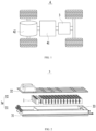
- FIG. 1 is a schematic structural diagram of a vehicle provided according to some embodiments of the present application.
- a battery 3 is provided inside a vehicle 4, and the battery 3 may be provided at the bottom, the head, or the tail of the vehicle 4.
- the battery 3 may be used for powering the vehicle 4.
- the battery 3 may serve as an operational power source of the vehicle 4.
- the vehicle 4 may also include a controller 41 and a motor 42.
- the controller 41 is used for controlling the battery 3 to power the motor 42, e.g., for operation power needed by the vehicle 4 for start-up, navigation, and driving.
- the battery 3 may not only serve as the operational power source for the vehicle 4, but also as a driving power source for the vehicle 4 to, instead of or in part instead of fuel or natural gas, provide driving power for the vehicle 4.
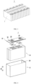
- the battery 3 may include a case 3a for accommodating the battery cells 1, and the case 3a may be of various structures.
- the case 3a may include a first case part 31 and a second case part 32.
- the first case part 31 and the second case part 32 are mutually lidded onto each other, and the first case part 31 and the second case part 32 jointly define a case space 33 for accommodating the battery cells.
- a seal such as a sealant or a gasket, may be further provided between the first case part 31 and the second case part 32.
- the plurality of battery cells 1 may be connected in series, in parallel, or in series-parallel.
- the series-parallel connection means that both series connection and parallel connection are present for the connection among the plurality of battery cells 1.
- the plurality of battery cells 1 may be directly connected in series, in parallel, or in series-parallel, and the whole formed by the plurality of battery cells 1 is then accommodated in the case 3a.
- the plurality of battery cells 1 may also be first connected in series, in parallel, or in series-parallel to form the battery module group 2; there may be one or more battery module groups 2, and the one or more battery module groups 2 are accommodated in the case 3a.
- the plurality of battery module groups 2 may be connected in series, in parallel, or in series-parallel to form a whole to be accommodated in the case 3a.
- FIG. 2 Illustratively, in FIG. 2 , the whole formed by a plurality of battery cells 1 is accommodated in the case 3a.
- FIG. 4 is a schematic exploded view of a battery cell provided according to some embodiments of the present application.
- the end cover assembly 22 includes an end cover 221, and the end cover 221 is lidded onto the opening of the housing 21.
- the end cover 221 may be of various structures.
- the end cover 221 may have a plate-like structure or a hollow structure with one end open.
- the housing 21 has a rectangular parallelepiped structure, the end cover 221 is of a plate-like structure, and the end cover 221 is lidded onto the opening at the top of the housing 21.
- the end cover 221 may be made of an insulating material (e.g., plastic) or a conductive material (e.g., metal).
- the end cover assembly 22 may further include an insulating member at a side of the end cover 221 facing the electrode assembly 10 to insulate and separate the end cover 221 from the electrode assembly 10.
- the end cover assembly 22 may further include an electrode terminal 222, and the electrode terminal 222 is mounted on the end cover 221.
- the two electrode terminals 222 are defined as a positive electrode terminal and a negative electrode terminal, respectively, and the positive electrode terminal and the negative electrode terminal are both used to be electrically connected to the electrode assembly 10 to output electric energy generated by the electrode assembly 10.
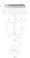
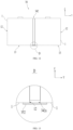
- the battery assembly 3b includes a plurality of battery modules 34 sequentially provided along the first direction X, and each battery module 34 includes a plurality of battery cells 1 sequentially provided along the second direction Y.
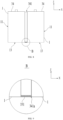
- the gap includes a first gap 341, the first gap 341 is located between two adjacent battery modules 34, and the first gap 341 includes two first openings 341a opposite to each other along the height direction Z.
- the protective assembly 35 includes first protective parts 351, and each of the first protective parts 351 connects two adjacent battery modules 34 and covers at least one first opening 341a of the first gap 341. Every two of the second direction Y, the first direction X, and the height direction Z are perpendicular to each other. It can be understood that, in the embodiments of the present application, the first direction X may be considered as the width direction of the battery cell 1, and the second direction Y may be considered as the length direction of the battery cell 1.
- the battery assembly 3b includes a plurality of battery modules 34 sequentially provided along the first direction X, and a cooling plate, a buffer pad, or the like may be provided between adjacent battery modules 34.
- a cooling plate may be provided between two adjacent battery modules 34.
- the first protective part 351 connects two adjacent battery modules 34, and the first protective part 351 and the battery module 34 may be connected in various ways.
- the battery cell 1 includes a bottom surface 13 on one side along the height direction Z, and the first protective part 351 is provided on the one side of the battery cell 1 along the height direction Z and is connected to at least a part of the bottom surface 13.
- the second protective part 352 extends along the first direction X and covers the second gaps 342 of a plurality of battery modules 34.
- the battery cell 1 includes two first surfaces 11 opposite to each other along the first direction X and two second surfaces 12 opposite to each other along the second direction Y.
- the first surface 11 is located between two second surfaces 12, the second surface 12 has an area smaller than that of the first surface 11, and the first surfaces 11 of two adjacent battery modules 34 are provided opposite to each other.
- the first surface 11 may be regarded as the large surface of the battery cell 1
- the second surface 12 may be regarded as the side surface of the battery cell 1.
- the large surface has a larger force-bearing area, and therefore the risk of uneven stress is larger. Therefore, as the first protective part 351 is provided between two adjacent battery modules 34, the first protective part 351 can effectively block the foreign matters that get into the space between two first surfaces 11 of two adjacent battery cells 1, such that the influence of foreign matters on the battery cells 1 is reduced as much as possible, the problem of uneven stress on the first surfaces 11 of the battery cells 1 caused by foreign matters is relieved, and the possibility of lithium plating on the battery cells 1 is reduced.
- the battery includes a case, a battery assembly 3b, and a protective assembly 35.
- the case includes a first case part having an accommodating cavity and a second case part lidded onto the first case part, and the first case part and the second case part are sequentially provided along the height direction Z.
- the battery assembly 3b is provided in the accommodating cavity, and the battery assembly 3b includes a plurality of battery cells 1.
- a gap is present between two adjacent battery cells 1, and the gap extends along the height direction Z of the battery cells 1 and the gap includes two openings opposite to each other along the height direction Z.
- the protective assembly 35 is connected to two adjacent battery cells 1 and covers the opening of the gap away from the second case part.
- the battery provided according to the embodiments of the present application includes the protective assembly 35, and the protective assembly 35 is connected to two adjacent battery cells 1 and covers the opening of the gap away from the second case part, such that the protective assembly 35 can block external foreign matters to some extent, and the problem of uneven stress on the battery cells 1 caused by foreign matters is relieved, and thus the possibility of lithium plating on the battery cells 1 is reduced, the cycle performance of the battery cells 1 is improved, and thereby the service life of the battery can be prolonged.
Landscapes
- Chemical & Material Sciences (AREA)
- Chemical Kinetics & Catalysis (AREA)
- Electrochemistry (AREA)
- General Chemical & Material Sciences (AREA)
- Engineering & Computer Science (AREA)
- Aviation & Aerospace Engineering (AREA)
- Battery Mounting, Suspending (AREA)
Applications Claiming Priority (2)
| Application Number | Priority Date | Filing Date | Title |
|---|---|---|---|
| CN202320203130.XU CN219246815U (zh) | 2023-02-14 | 2023-02-14 | 电池和用电装置 |
| PCT/CN2023/098435 WO2024169085A1 (fr) | 2023-02-14 | 2023-06-05 | Batterie et dispositif électrique |
Publications (2)
| Publication Number | Publication Date |
|---|---|
| EP4583277A1 true EP4583277A1 (fr) | 2025-07-09 |
| EP4583277A4 EP4583277A4 (fr) | 2026-04-08 |
Family
ID=86803779
Family Applications (1)
| Application Number | Title | Priority Date | Filing Date |
|---|---|---|---|
| EP23922212.8A Pending EP4583277A4 (fr) | 2023-02-14 | 2023-06-05 | Batterie et dispositif électrique |
Country Status (6)
| Country | Link |
|---|---|
| US (1) | US20250233244A1 (fr) |
| EP (1) | EP4583277A4 (fr) |
| JP (1) | JP2025533580A (fr) |
| KR (1) | KR20250053184A (fr) |
| CN (1) | CN219246815U (fr) |
| WO (1) | WO2024169085A1 (fr) |
Families Citing this family (1)
| Publication number | Priority date | Publication date | Assignee | Title |
|---|---|---|---|---|
| CN222763019U (zh) * | 2024-02-26 | 2025-04-15 | 宁德时代新能源科技股份有限公司 | 电池模组、电池及用电装置 |
Family Cites Families (11)
| Publication number | Priority date | Publication date | Assignee | Title |
|---|---|---|---|---|
| JP5173227B2 (ja) * | 2007-03-30 | 2013-04-03 | 三洋電機株式会社 | パック電池 |
| JP5537111B2 (ja) * | 2009-09-30 | 2014-07-02 | 株式会社東芝 | 二次電池装置 |
| JP2015172997A (ja) * | 2012-07-13 | 2015-10-01 | 三洋電機株式会社 | バッテリシステム及びバッテリシステムを備える車両並びに蓄電装置 |
| JP6238106B2 (ja) * | 2013-04-08 | 2017-11-29 | 株式会社Gsユアサ | 蓄電モジュール、蓄電装置及び風路接続部材 |
| JP2018060595A (ja) * | 2015-02-27 | 2018-04-12 | 三洋電機株式会社 | 電源装置及びこれを備える車両 |
| US20180261813A1 (en) * | 2017-03-10 | 2018-09-13 | NextEv USA, Inc. | Thermally conductive potting for module retainer and thermal link |
| US12362422B2 (en) * | 2019-08-30 | 2025-07-15 | Panasonic Intellectual Property Management Co., Ltd. | Power storage module |
| HUE059770T2 (hu) * | 2020-03-27 | 2022-12-28 | Samsung Sdi Co Ltd | Eljárás prizma alakú akkumulátor cellák halmazatának összeállítására, prizma alakú akkumulátor cellák halmazata, akkumulátor modul, és jármû, ahol ez magában foglal egy akkumulátor csomagot, amely tartalmaz legalább egy akkumulátor modult |
| CN215731892U (zh) * | 2021-08-13 | 2022-02-01 | 欣旺达电动汽车电池有限公司 | 电池箱及电池包 |
| CN117613498A (zh) * | 2022-02-18 | 2024-02-27 | 宁德时代新能源科技股份有限公司 | 电池、用电设备、制备电池的方法和设备 |
| CN218274957U (zh) * | 2022-05-17 | 2023-01-10 | 宁德时代新能源科技股份有限公司 | 电池和用电装置 |
-
2023
- 2023-02-14 CN CN202320203130.XU patent/CN219246815U/zh active Active
- 2023-06-05 WO PCT/CN2023/098435 patent/WO2024169085A1/fr not_active Ceased
- 2023-06-05 KR KR1020257009792A patent/KR20250053184A/ko active Pending
- 2023-06-05 JP JP2025517880A patent/JP2025533580A/ja active Pending
- 2023-06-05 EP EP23922212.8A patent/EP4583277A4/fr active Pending
-
2025
- 2025-04-03 US US19/098,987 patent/US20250233244A1/en active Pending
Also Published As
| Publication number | Publication date |
|---|---|
| WO2024169085A1 (fr) | 2024-08-22 |
| CN219246815U (zh) | 2023-06-23 |
| KR20250053184A (ko) | 2025-04-21 |
| US20250233244A1 (en) | 2025-07-17 |
| JP2025533580A (ja) | 2025-10-07 |
| EP4583277A4 (fr) | 2026-04-08 |
Similar Documents
| Publication | Publication Date | Title |
|---|---|---|
| US20240313340A1 (en) | Battery cell, battery, and power consuming device | |
| US20250105410A1 (en) | End cover assembly, battery cell, battery, and electric apparatus | |
| US20240274925A1 (en) | Battery cell, manufacturing method and system thereof, battery, and powered device | |
| US20230207946A1 (en) | Case, battery, power consuming device, and method for assembling case | |
| US20250015426A1 (en) | Housing, battery cell, battery, and power consuming device | |
| US20250140991A1 (en) | Battery cell, battery, and electrical consuming device | |
| US20240120608A1 (en) | End cap, battery cell, battery and power consuming device | |
| US20240283059A1 (en) | Battery cell, method and system for manufacturing battery cell, battery, and electrical device | |
| EP4668467A1 (fr) | Élément de batterie, batterie et appareil électrique | |
| US20240047802A1 (en) | Battery, manufacturing method and manufacturing system thereof and electric device | |
| US20240283109A1 (en) | Battery cell, method and system for manufacturing battery cell, battery and electrical apparatus | |
| US20240396128A1 (en) | Battery cell, battery, and electric device | |
| CN218351639U (zh) | 端盖组件、电池组件、电池及用电设备 | |
| US20240162579A1 (en) | Battery cell, method and system for manufacturing battery cell, battery and electrical apparatus | |
| US20250233244A1 (en) | Battery and electric device | |
| US20240055705A1 (en) | Battery cell, battery, power consuming apparatus, and method and apparatus for manufacturing battery cell | |
| US20240250346A1 (en) | Battery cell, method and system for manufacturing battery cell, battery and electrical device | |
| US20230369712A1 (en) | End cap, battery cell, battery and power consuming device | |
| WO2024178536A1 (fr) | Batterie et appareil électrique | |
| US20250087789A1 (en) | Battery cell, battery, and electric apparatus | |
| CN220492033U (zh) | 电池的箱体、电池以及用电装置 | |
| US20250079664A1 (en) | Battery cell, battery and electrical equipment | |
| US20240106039A1 (en) | Battery cell, battery, electrical device, and method and device for manufacturing battery cell | |
| US20240396127A1 (en) | End cover assembly, battery cell, battery, and electrical device | |
| CN121394515A (zh) | 极片的制造方法、电池单体、电池装置和用电装置 |
Legal Events
| Date | Code | Title | Description |
|---|---|---|---|
| STAA | Information on the status of an ep patent application or granted ep patent |
Free format text: STATUS: THE INTERNATIONAL PUBLICATION HAS BEEN MADE |
|
| PUAI | Public reference made under article 153(3) epc to a published international application that has entered the european phase |
Free format text: ORIGINAL CODE: 0009012 |
|
| STAA | Information on the status of an ep patent application or granted ep patent |
Free format text: STATUS: REQUEST FOR EXAMINATION WAS MADE |
|
| 17P | Request for examination filed |
Effective date: 20250331 |
|
| AK | Designated contracting states |
Kind code of ref document: A1 Designated state(s): AL AT BE BG CH CY CZ DE DK EE ES FI FR GB GR HR HU IE IS IT LI LT LU LV MC ME MK MT NL NO PL PT RO RS SE SI SK SM TR |
|
| A4 | Supplementary search report drawn up and despatched |
Effective date: 20260310 |
|
| RIC1 | Information provided on ipc code assigned before grant |
Ipc: H01M 50/24 20210101AFI20260304BHEP Ipc: H01M 50/204 20210101ALI20260304BHEP Ipc: H01M 50/289 20210101ALI20260304BHEP |