EP4583280A1 - Structure de refroidissement, batterie et dispositif électrique - Google Patents
Structure de refroidissement, batterie et dispositif électrique Download PDFInfo
- Publication number
- EP4583280A1 EP4583280A1 EP22958000.6A EP22958000A EP4583280A1 EP 4583280 A1 EP4583280 A1 EP 4583280A1 EP 22958000 A EP22958000 A EP 22958000A EP 4583280 A1 EP4583280 A1 EP 4583280A1
- Authority
- EP
- European Patent Office
- Prior art keywords
- cooling structure
- battery
- cooling
- cooling body
- buffer section
- Prior art date
- Legal status (The legal status is an assumption and is not a legal conclusion. Google has not performed a legal analysis and makes no representation as to the accuracy of the status listed.)
- Pending
Links
Images


Classifications
-
- H—ELECTRICITY
- H01—ELECTRIC ELEMENTS
- H01M—PROCESSES OR MEANS, e.g. BATTERIES, FOR THE DIRECT CONVERSION OF CHEMICAL ENERGY INTO ELECTRICAL ENERGY
- H01M10/00—Secondary cells; Manufacture thereof
- H01M10/60—Heating or cooling; Temperature control
- H01M10/62—Heating or cooling; Temperature control specially adapted for specific applications
- H01M10/625—Vehicles
-
- H—ELECTRICITY
- H01—ELECTRIC ELEMENTS
- H01M—PROCESSES OR MEANS, e.g. BATTERIES, FOR THE DIRECT CONVERSION OF CHEMICAL ENERGY INTO ELECTRICAL ENERGY
- H01M10/00—Secondary cells; Manufacture thereof
- H01M10/60—Heating or cooling; Temperature control
- H01M10/61—Types of temperature control
- H01M10/613—Cooling or keeping cold
-
- H—ELECTRICITY
- H01—ELECTRIC ELEMENTS
- H01M—PROCESSES OR MEANS, e.g. BATTERIES, FOR THE DIRECT CONVERSION OF CHEMICAL ENERGY INTO ELECTRICAL ENERGY
- H01M10/00—Secondary cells; Manufacture thereof
- H01M10/60—Heating or cooling; Temperature control
- H01M10/65—Means for temperature control structurally associated with the cells
- H01M10/655—Solid structures for heat exchange or heat conduction
- H01M10/6554—Rods or plates
- H01M10/6555—Rods or plates arranged between the cells
-
- H—ELECTRICITY
- H01—ELECTRIC ELEMENTS
- H01M—PROCESSES OR MEANS, e.g. BATTERIES, FOR THE DIRECT CONVERSION OF CHEMICAL ENERGY INTO ELECTRICAL ENERGY
- H01M10/00—Secondary cells; Manufacture thereof
- H01M10/60—Heating or cooling; Temperature control
- H01M10/65—Means for temperature control structurally associated with the cells
- H01M10/655—Solid structures for heat exchange or heat conduction
- H01M10/6556—Solid parts with flow channel passages or pipes for heat exchange
-
- H—ELECTRICITY
- H01—ELECTRIC ELEMENTS
- H01M—PROCESSES OR MEANS, e.g. BATTERIES, FOR THE DIRECT CONVERSION OF CHEMICAL ENERGY INTO ELECTRICAL ENERGY
- H01M10/00—Secondary cells; Manufacture thereof
- H01M10/60—Heating or cooling; Temperature control
- H01M10/65—Means for temperature control structurally associated with the cells
- H01M10/655—Solid structures for heat exchange or heat conduction
- H01M10/6556—Solid parts with flow channel passages or pipes for heat exchange
- H01M10/6557—Solid parts with flow channel passages or pipes for heat exchange arranged between the cells
-
- H—ELECTRICITY
- H01—ELECTRIC ELEMENTS
- H01M—PROCESSES OR MEANS, e.g. BATTERIES, FOR THE DIRECT CONVERSION OF CHEMICAL ENERGY INTO ELECTRICAL ENERGY
- H01M50/00—Constructional details or processes of manufacture of the non-active parts of electrochemical cells other than fuel cells, e.g. hybrid cells
- H01M50/20—Mountings; Secondary casings or frames; Racks, modules or packs; Suspension devices; Shock absorbers; Transport or carrying devices; Holders
- H01M50/204—Racks, modules or packs for multiple batteries or multiple cells
- H01M50/207—Racks, modules or packs for multiple batteries or multiple cells characterised by their shape
- H01M50/209—Racks, modules or packs for multiple batteries or multiple cells characterised by their shape adapted for prismatic or rectangular cells
-
- H—ELECTRICITY
- H01—ELECTRIC ELEMENTS
- H01M—PROCESSES OR MEANS, e.g. BATTERIES, FOR THE DIRECT CONVERSION OF CHEMICAL ENERGY INTO ELECTRICAL ENERGY
- H01M50/00—Constructional details or processes of manufacture of the non-active parts of electrochemical cells other than fuel cells, e.g. hybrid cells
- H01M50/20—Mountings; Secondary casings or frames; Racks, modules or packs; Suspension devices; Shock absorbers; Transport or carrying devices; Holders
- H01M50/233—Mountings; Secondary casings or frames; Racks, modules or packs; Suspension devices; Shock absorbers; Transport or carrying devices; Holders characterised by physical properties of casings or racks, e.g. dimensions
- H01M50/242—Mountings; Secondary casings or frames; Racks, modules or packs; Suspension devices; Shock absorbers; Transport or carrying devices; Holders characterised by physical properties of casings or racks, e.g. dimensions adapted for protecting batteries against vibrations, collision impact or swelling
-
- H—ELECTRICITY
- H01—ELECTRIC ELEMENTS
- H01M—PROCESSES OR MEANS, e.g. BATTERIES, FOR THE DIRECT CONVERSION OF CHEMICAL ENERGY INTO ELECTRICAL ENERGY
- H01M50/00—Constructional details or processes of manufacture of the non-active parts of electrochemical cells other than fuel cells, e.g. hybrid cells
- H01M50/20—Mountings; Secondary casings or frames; Racks, modules or packs; Suspension devices; Shock absorbers; Transport or carrying devices; Holders
- H01M50/244—Secondary casings; Racks; Suspension devices; Carrying devices; Holders characterised by their mounting method
-
- H—ELECTRICITY
- H01—ELECTRIC ELEMENTS
- H01M—PROCESSES OR MEANS, e.g. BATTERIES, FOR THE DIRECT CONVERSION OF CHEMICAL ENERGY INTO ELECTRICAL ENERGY
- H01M50/00—Constructional details or processes of manufacture of the non-active parts of electrochemical cells other than fuel cells, e.g. hybrid cells
- H01M50/20—Mountings; Secondary casings or frames; Racks, modules or packs; Suspension devices; Shock absorbers; Transport or carrying devices; Holders
- H01M50/249—Mountings; Secondary casings or frames; Racks, modules or packs; Suspension devices; Shock absorbers; Transport or carrying devices; Holders specially adapted for aircraft or vehicles, e.g. cars or trains
-
- H—ELECTRICITY
- H01—ELECTRIC ELEMENTS
- H01M—PROCESSES OR MEANS, e.g. BATTERIES, FOR THE DIRECT CONVERSION OF CHEMICAL ENERGY INTO ELECTRICAL ENERGY
- H01M2220/00—Batteries for particular applications
- H01M2220/20—Batteries in motive systems, e.g. vehicle, ship, plane
-
- H—ELECTRICITY
- H01—ELECTRIC ELEMENTS
- H01M—PROCESSES OR MEANS, e.g. BATTERIES, FOR THE DIRECT CONVERSION OF CHEMICAL ENERGY INTO ELECTRICAL ENERGY
- H01M50/00—Constructional details or processes of manufacture of the non-active parts of electrochemical cells other than fuel cells, e.g. hybrid cells
- H01M50/20—Mountings; Secondary casings or frames; Racks, modules or packs; Suspension devices; Shock absorbers; Transport or carrying devices; Holders
- H01M50/204—Racks, modules or packs for multiple batteries or multiple cells
-
- Y—GENERAL TAGGING OF NEW TECHNOLOGICAL DEVELOPMENTS; GENERAL TAGGING OF CROSS-SECTIONAL TECHNOLOGIES SPANNING OVER SEVERAL SECTIONS OF THE IPC; TECHNICAL SUBJECTS COVERED BY FORMER USPC CROSS-REFERENCE ART COLLECTIONS [XRACs] AND DIGESTS
- Y02—TECHNOLOGIES OR APPLICATIONS FOR MITIGATION OR ADAPTATION AGAINST CLIMATE CHANGE
- Y02E—REDUCTION OF GREENHOUSE GAS [GHG] EMISSIONS, RELATED TO ENERGY GENERATION, TRANSMISSION OR DISTRIBUTION
- Y02E60/00—Enabling technologies; Technologies with a potential or indirect contribution to GHG emissions mitigation
- Y02E60/10—Energy storage using batteries
Definitions
- the battery cells in the battery assembly will press each other due to thermal expansion to cause both the battery cells and the cooling structure bear great stress, causing the battery to be easily damaged and affecting normal use.
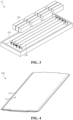
- an embodiment of the present application provides a cooling structure, comprising: a cooling body provided with a flow channel inside; and a supporting member provided in the flow channel; wherein the supporting member comprises at least two connecting sections and a plurality of buffer sections, every two adjacent connecting sections are fixedly connected to the two opposite inner surfaces of the cooling body along the thickness direction, and the buffer section connects two adjacent connecting sections and is configured to be able to elastically deform after being stressed.
- the supporting member is arranged in the flow channel of the cooling body, and every two adjacent connecting sections of the supporting member are fixedly connected to the two opposite inner surfaces of the cooling body in the thickness direction, by which the cooling body can be supported in its thickness direction.
- the buffer section connects two adjacent connecting sections and is configured to be able to elastically deform after being stressed. In this way, when the cooling body is stressed, the buffer section can absorb part of the stress and elastically deform, and the stress on the cold plate is dispersed through the entire supporting member to avoid stress concentration and reduce the impact of the stress on the cooling structure and battery cells, making the battery less susceptible to damage and ensuring its normal use.
- each of the connecting sections is attached to the inner surface of the cooling body, and at least one connecting section is provided with a protruding portion protruding toward the center of the flow channel along the thickness direction of the cooling body.
- the protruding portion comprises a top wall and side walls respectively connected to both sides of the top wall; and the angle between the top wall and the side walls is greater than or equal to 90° and less than 180°.
- the plane where the top wall is located is parallel to the inner surface of the cooling body; the distance between the top wall and the inner surface of the cooling body connected to the top wall through the side wall is greater than or equal to 1 millimeter (mm) and less than or equal to 3 millimeters (mm).
- the contact area between the protruding portion and the inner surface of the cooling body can be increased, making the protruding portion more uniformly stressed and the structure more stable.
- the protruding height of the protruding portion is changed, making it easy to adjust the protruding degree of the protruding portion.
- the protruding portion is arranged symmetrically about the center line of the connecting section where it is located. Such a design allows the protruding portion to be located at the center of the connection end where it is located. In this way, the force distribution between the protruding portion and the connecting section is more uniform and the structural stability is higher.
- the cross-sectional shape of the buffer section is a straight line, a polyline or an arc.
- connection between the connecting section and the buffer section is in smooth transition.
- the connections between the connecting section and the buffer section are all on the inner surface of the cooling body.
- the cooling structure further comprises a driving member connected to the buffer section to drive the buffer section to elastically deform, or to drive the buffer section to return to the state before elastic deformation.
- a driving member connected to the buffer section in the cooling structure, even if the cooling body is not subjected to external pressure, the driving member can drive the buffer section to elastically deform, and the shape of the cooling body can be changed in advance with the help of the active deformation of the buffer section to prevent it from being subjected to great pressure, which protects the cooling body, and makes it more flexible to use.
- an embodiment of the present application further provides a battery, comprising: a box body; a battery cell, accommodated in the box body; and the cooling structure as described above, wherein the cooling structure is attached to one or more sides of the battery cell.
- the above-mentioned cooling structure is adopted, the supporting member is arranged in the flow channel of the cooling body, and every two adjacent connecting sections of the supporting member are fixedly connected to the two opposite inner surfaces of the cooling body in the thickness direction, which can support the cooling body in the its thickness direction.
- the buffer section connects two adjacent connecting sections and is configured to be able to elastically deform after being stressed. In this way, when the cooling body is stressed, the buffer section can absorb part of the stress and elastically deform, and the stress on the cold plate is dispersed through the entire supporting member to avoid stress concentration and reduce the impact of the stress on the cooling structure and battery cells, making the battery less susceptible to damage and ensuring its normal use.
- FIG. 1 is a schematic diagram showing the overall structure of a vehicle provided by an embodiment of the present application.
- the cooling structure 100 is disposed on one or more sides of the battery cell 300 during use, when the battery cell 300 expands due to heat, it will press the cooling structure 100. Therefore, in an embodiment of the present application, the cooling structure 100 further comprises a supporting member 120.
- the supporting member 120 is provided in the flow channel 111 of the cooling body 110 to support the cooling body 110.
- the supporting member 120 comprises at least two connecting sections 121 and a plurality of buffer sections 122. Every two adjacent connecting sections 121 are fixedly connected to the two opposite inner surfaces of the cooling body 110 along the thickness direction, that is, the cooling body 110 has two opposite inner surfaces in its thickness direction.
Landscapes
- Chemical & Material Sciences (AREA)
- Chemical Kinetics & Catalysis (AREA)
- Electrochemistry (AREA)
- General Chemical & Material Sciences (AREA)
- Engineering & Computer Science (AREA)
- Manufacturing & Machinery (AREA)
- Aviation & Aerospace Engineering (AREA)
- Secondary Cells (AREA)
- Battery Mounting, Suspending (AREA)
Applications Claiming Priority (2)
| Application Number | Priority Date | Filing Date | Title |
|---|---|---|---|
| CN202222344157.9U CN218334077U (zh) | 2022-09-05 | 2022-09-05 | 冷却结构、电池及用电装置 |
| PCT/CN2022/142788 WO2024051044A1 (fr) | 2022-09-05 | 2022-12-28 | Structure de refroidissement, batterie et dispositif électrique |
Publications (2)
| Publication Number | Publication Date |
|---|---|
| EP4583280A1 true EP4583280A1 (fr) | 2025-07-09 |
| EP4583280A4 EP4583280A4 (fr) | 2026-01-28 |
Family
ID=84832419
Family Applications (1)
| Application Number | Title | Priority Date | Filing Date |
|---|---|---|---|
| EP22958000.6A Pending EP4583280A4 (fr) | 2022-09-05 | 2022-12-28 | Structure de refroidissement, batterie et dispositif électrique |
Country Status (4)
| Country | Link |
|---|---|
| US (1) | US20250201963A1 (fr) |
| EP (1) | EP4583280A4 (fr) |
| CN (1) | CN218334077U (fr) |
| WO (1) | WO2024051044A1 (fr) |
Families Citing this family (4)
| Publication number | Priority date | Publication date | Assignee | Title |
|---|---|---|---|---|
| CN219350392U (zh) * | 2023-03-23 | 2023-07-14 | 欣旺达电动汽车电池有限公司 | 电池包及用电装置 |
| CN116093515B (zh) * | 2023-04-11 | 2023-08-25 | 宁德时代新能源科技股份有限公司 | 电池及用电装置 |
| CN116799415B (zh) * | 2023-08-18 | 2024-01-02 | 欣旺达动力科技股份有限公司 | 一种电池包及用电设备 |
| CN118380683B (zh) * | 2024-05-17 | 2024-10-29 | 江苏正力新能电池技术股份有限公司 | 电池及风冷组件的设计方法 |
Family Cites Families (6)
| Publication number | Priority date | Publication date | Assignee | Title |
|---|---|---|---|---|
| US20100243225A1 (en) * | 2006-01-19 | 2010-09-30 | Werner Zobel | Flat tube, flat tube heat exchanger, and method of manufacturing same |
| US11509005B2 (en) * | 2018-03-09 | 2022-11-22 | Kabushiki Kaisha Toshiba | Battery pack including separator between secondary batteries |
| KR102391984B1 (ko) * | 2018-05-23 | 2022-04-27 | 주식회사 엘지에너지솔루션 | 전지 모듈용 냉각 부재 및 이를 포함하는 전지팩 |
| JP7307193B2 (ja) * | 2019-06-18 | 2023-07-11 | 寧徳時代新能源科技股▲分▼有限公司 | 温度制御ユニット及び電池パック |
| CN112103421B (zh) * | 2019-06-18 | 2021-10-22 | 宁德时代新能源科技股份有限公司 | 温控组件及电池包 |
| CN217158339U (zh) * | 2022-04-14 | 2022-08-09 | 宁德时代新能源科技股份有限公司 | 冷却装置、电池及用电装置 |
-
2022
- 2022-09-05 CN CN202222344157.9U patent/CN218334077U/zh active Active
- 2022-12-28 WO PCT/CN2022/142788 patent/WO2024051044A1/fr not_active Ceased
- 2022-12-28 EP EP22958000.6A patent/EP4583280A4/fr active Pending
-
2025
- 2025-03-05 US US19/070,631 patent/US20250201963A1/en active Pending
Also Published As
| Publication number | Publication date |
|---|---|
| WO2024051044A1 (fr) | 2024-03-14 |
| WO2024051044A8 (fr) | 2024-04-11 |
| EP4583280A4 (fr) | 2026-01-28 |
| CN218334077U (zh) | 2023-01-17 |
| WO2024051044A9 (fr) | 2025-07-03 |
| US20250201963A1 (en) | 2025-06-19 |
Similar Documents
| Publication | Publication Date | Title |
|---|---|---|
| EP4583280A1 (fr) | Structure de refroidissement, batterie et dispositif électrique | |
| US20250055069A1 (en) | Thermal management component, battery, and electric apparatus | |
| CN219203266U (zh) | 电池以及用电装置 | |
| WO2023201923A1 (fr) | Ensemble plaque de refroidissement d'eau, système de refroidissement d'eau, batterie et corps de boîte associé, et dispositif électrique | |
| WO2023029504A1 (fr) | Compartiment de batterie, batterie et dispositif électrique | |
| CN217114537U (zh) | 一种电池及用电装置 | |
| EP4468452A1 (fr) | Dispositif de gestion thermique, batterie et dispositif électrique | |
| US20250233242A1 (en) | Box assembly, battery, and electric apparatus | |
| US20240213577A1 (en) | Battery module, battery thermal management system, and electric device | |
| US20250023168A1 (en) | Battery and electric-consuming device | |
| US20250038301A1 (en) | Battery and power consuming apparatus | |
| EP4376188A1 (fr) | Batterie et dispositif électrique | |
| CN217158339U (zh) | 冷却装置、电池及用电装置 | |
| WO2025107844A1 (fr) | Composant de gestion thermique, batterie et dispositif électrique | |
| WO2023245502A1 (fr) | Composant de gestion thermique, système de gestion thermique, batterie et dispositif électrique | |
| CN218414770U (zh) | 电池包及电池舱 | |
| US20250293342A1 (en) | Battery and electric device | |
| US20250279498A1 (en) | Battery and power consuming apparatus with same | |
| CN222775406U (zh) | 电池及用电装置 | |
| WO2025200226A9 (fr) | Batterie et dispositif électrique | |
| EP4567986A1 (fr) | Batterie et dispositif électrique | |
| CN221766956U (zh) | 电池及用电设备 | |
| CN222106852U (zh) | 电池及用电装置 | |
| CN221668929U (zh) | 换热部件、电池及用电装置 | |
| US20260051559A1 (en) | Battery and electrical device |
Legal Events
| Date | Code | Title | Description |
|---|---|---|---|
| STAA | Information on the status of an ep patent application or granted ep patent |
Free format text: STATUS: THE INTERNATIONAL PUBLICATION HAS BEEN MADE |
|
| PUAI | Public reference made under article 153(3) epc to a published international application that has entered the european phase |
Free format text: ORIGINAL CODE: 0009012 |
|
| STAA | Information on the status of an ep patent application or granted ep patent |
Free format text: STATUS: REQUEST FOR EXAMINATION WAS MADE |
|
| 17P | Request for examination filed |
Effective date: 20250404 |
|
| AK | Designated contracting states |
Kind code of ref document: A1 Designated state(s): AL AT BE BG CH CY CZ DE DK EE ES FI FR GB GR HR HU IE IS IT LI LT LU LV MC ME MK MT NL NO PL PT RO RS SE SI SK SM TR |
|
| DAV | Request for validation of the european patent (deleted) | ||
| DAX | Request for extension of the european patent (deleted) | ||
| A4 | Supplementary search report drawn up and despatched |
Effective date: 20260105 |
|
| RIC1 | Information provided on ipc code assigned before grant |
Ipc: H01M 50/242 20210101AFI20251219BHEP Ipc: H01M 10/613 20140101ALI20251219BHEP Ipc: H01M 10/625 20140101ALI20251219BHEP Ipc: H01M 10/6555 20140101ALI20251219BHEP Ipc: H01M 10/6557 20140101ALI20251219BHEP Ipc: H01M 50/204 20210101ALI20251219BHEP Ipc: H01M 50/209 20210101ALI20251219BHEP Ipc: H01M 50/244 20210101ALI20251219BHEP Ipc: H01M 50/249 20210101ALI20251219BHEP Ipc: H01M 10/6556 20140101ALI20251219BHEP |