EP4583321A1 - Prise de courant électrique - Google Patents
Prise de courant électrique Download PDFInfo
- Publication number
- EP4583321A1 EP4583321A1 EP24382007.3A EP24382007A EP4583321A1 EP 4583321 A1 EP4583321 A1 EP 4583321A1 EP 24382007 A EP24382007 A EP 24382007A EP 4583321 A1 EP4583321 A1 EP 4583321A1
- Authority
- EP
- European Patent Office
- Prior art keywords
- cover
- pins
- power outlet
- assembly
- sub
- Prior art date
- Legal status (The legal status is an assumption and is not a legal conclusion. Google has not performed a legal analysis and makes no representation as to the accuracy of the status listed.)
- Granted
Links
Images



Classifications
-
- H—ELECTRICITY
- H01—ELECTRIC ELEMENTS
- H01R—ELECTRICALLY-CONDUCTIVE CONNECTIONS; STRUCTURAL ASSOCIATIONS OF A PLURALITY OF MUTUALLY-INSULATED ELECTRICAL CONNECTING ELEMENTS; COUPLING DEVICES; CURRENT COLLECTORS
- H01R13/00—Details of coupling devices of the kinds covered by groups H01R12/70 or H01R24/00 - H01R33/00
- H01R13/44—Means for preventing access to live contacts
- H01R13/447—Shutter or cover plate
- H01R13/453—Shutter or cover plate opened by engagement of counterpart
- H01R13/4532—Rotating shutter
-
- H—ELECTRICITY
- H01—ELECTRIC ELEMENTS
- H01R—ELECTRICALLY-CONDUCTIVE CONNECTIONS; STRUCTURAL ASSOCIATIONS OF A PLURALITY OF MUTUALLY-INSULATED ELECTRICAL CONNECTING ELEMENTS; COUPLING DEVICES; CURRENT COLLECTORS
- H01R13/00—Details of coupling devices of the kinds covered by groups H01R12/70 or H01R24/00 - H01R33/00
- H01R13/44—Means for preventing access to live contacts
- H01R13/447—Shutter or cover plate
- H01R13/453—Shutter or cover plate opened by engagement of counterpart
- H01R13/4538—Covers sliding or withdrawing in the direction of engagement
-
- H—ELECTRICITY
- H01—ELECTRIC ELEMENTS
- H01R—ELECTRICALLY-CONDUCTIVE CONNECTIONS; STRUCTURAL ASSOCIATIONS OF A PLURALITY OF MUTUALLY-INSULATED ELECTRICAL CONNECTING ELEMENTS; COUPLING DEVICES; CURRENT COLLECTORS
- H01R2103/00—Two poles
-
- H—ELECTRICITY
- H01—ELECTRIC ELEMENTS
- H01R—ELECTRICALLY-CONDUCTIVE CONNECTIONS; STRUCTURAL ASSOCIATIONS OF A PLURALITY OF MUTUALLY-INSULATED ELECTRICAL CONNECTING ELEMENTS; COUPLING DEVICES; CURRENT COLLECTORS
- H01R24/00—Two-part coupling devices, or either of their cooperating parts, characterised by their overall structure
- H01R24/76—Two-part coupling devices, or either of their cooperating parts, characterised by their overall structure with sockets, clips or analogous contacts and secured to apparatus or structure, e.g. to a wall
- H01R24/78—Two-part coupling devices, or either of their cooperating parts, characterised by their overall structure with sockets, clips or analogous contacts and secured to apparatus or structure, e.g. to a wall with additional earth or shield contacts
Definitions
- the present invention relates to the technical sector of power outlets intended to be fixed on flat surfaces, normally walls or partitions, and which consist, essentially although not exclusively, of a fastening frame for fastening to said surface, a mechanism box, a functionally diverse sub-assembly that includes at least one cover, and possible corresponding trim elements.
- the aforementioned sub-assembly usually includes a cover that has, on a front surface that is visible to the user, holes for the passage of the pins of the corresponding plug.
- the power outlet in particular the mechanism box, incorporates elastic means to allow the axial collapse of the cover, towards the wall, and its subsequent recovery until it is level with the decorative frame.
- One of the common solutions to fasten the sub-assembly to this front cover is to use the frame of the outlet that is mounted on the wall as an anchoring area for the same.
- patent EP3512045 in which the sub-assembly is fastened to the frame, and in which the axial movement of the cover of the outlet is limited by a stop comprised in the mechanism box.
- the present invention provides an electrical power outlet with the following features.
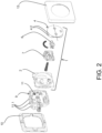
- the following parts known in outlets of this type are distinguished: a fastening frame to fasten the outlet on a mounting wall, a mechanism box, an exterior trim and a sub-assembly that includes an axially movable cover in a casing, and a shutter and a housing inside said casing of the sub-assembly.
- a series of guide pins In order to mount the axially movable cover in casing of the sub-assembly, there are a series of guide pins.
- the casing of the aforementioned sub-assembly includes corresponding slots (in a one-to-one correspondence with respect to the pins) arranged so as to guide the movement of the pins and, therefore, the cover, in its axial movement, limiting the lateral movement of the pins with at least one side wall of the slots.
- the upper and lower arrangement of the pins of the cover prevents their interaction with the claws, determining a more robust configuration adaptable to any type of electrical outlet.
- the guidance of the slots of the casing acts as a lateral stop for the pins of the cover, thereby avoiding misalignments or jamming of said cover in its axial movement.
- the axial guide pins comprise an upper projection or edge and a lower projection or edge; in this case, “upper” and “lower” refer to a position along the pin from the part of the pin closest to the cover or furthest from the mounting wall (upper projection) to the part furthest from the cover or closest to the mounting wall (lower projection).
- the projections and the complementary action stop project in opposite directions; in a preferred case, the projections project radially outwards from the outlet and the respective stop projects radially inwards from the outlet.
- the pin comprises an upper projection, aligned with the surface of the cover, and a lower projection, both projections projecting outward from the centre of the power outlet, and the casing comprising a stop configured such that, in the operational position, the stop limits the downwards axial movement of the cover by physical contact with the upper projection, and in the inactive position, it limits the upwards axial movement of the cover with the lower projection.
- Operaational position means the mounted position of the power outlet and when the plug is inserted into the power outlet, and "inactive position” when there is no plug inserted.
- the sub-assembly itself comprises, in the casing and in the corresponding pins of the cover, both the guide elements of the cover and the axial movement stop elements, unlike the documents known in the state of the art in which the intervention of the mechanism box is necessary for correct movement of the cover.
- the dimensions of the outlet sub-assembly are reduced, obtaining a more compact and aesthetic power outlet, and with less probability of failures derived from jams that may occur due to the intervention of several pieces for guidance.
- only the sub-assembly is replaced if it has defects or due to aesthetic modifications.
- the sub-assembly will be fastened to the mechanism box in a removable manner by means of fastening means such as clipping.
- the fastening of the sub-assembly to the mechanism box by means of clipping elements arranged on the sub-assembly in correspondence with fastening elements arranged in the mechanism box facilitates the assembly and disassembly of the power outlet, preventing the frame from being released when handled or from being forced thus misaligning said frame with the consequent aesthetic defects of the mounted electrical outlet.
- each corresponding slot comprises a side guide wall; this side guide wall is located in the part of each slot furthest from the centre of the outlet, in such a way that a surface of the corresponding pin laterally abuts against that part of the slot furthest from the centre of the outlet when the pin moves axially, guiding the correct positioning of the entire cover.
- Each slot could comprise only that side guide wall furthest from the centre, or, also, another additional side guide wall closer to the centre of the outlet, thereby constituting a kind of channel through which moves the respective pin.
Landscapes
- Connector Housings Or Holding Contact Members (AREA)
Priority Applications (1)
| Application Number | Priority Date | Filing Date | Title |
|---|---|---|---|
| EP24382007.3A EP4583321B1 (fr) | 2024-01-04 | 2024-01-04 | Prise de courant électrique |
Applications Claiming Priority (1)
| Application Number | Priority Date | Filing Date | Title |
|---|---|---|---|
| EP24382007.3A EP4583321B1 (fr) | 2024-01-04 | 2024-01-04 | Prise de courant électrique |
Publications (2)
| Publication Number | Publication Date |
|---|---|
| EP4583321A1 true EP4583321A1 (fr) | 2025-07-09 |
| EP4583321B1 EP4583321B1 (fr) | 2026-04-01 |
Family
ID=89843268
Family Applications (1)
| Application Number | Title | Priority Date | Filing Date |
|---|---|---|---|
| EP24382007.3A Active EP4583321B1 (fr) | 2024-01-04 | 2024-01-04 | Prise de courant électrique |
Country Status (1)
| Country | Link |
|---|---|
| EP (1) | EP4583321B1 (fr) |
Citations (3)
| Publication number | Priority date | Publication date | Assignee | Title |
|---|---|---|---|---|
| EP3512045A1 (fr) | 2018-01-15 | 2019-07-17 | Schneider Electric España, S.A. | Prise électrique |
| EP3945642A1 (fr) * | 2020-07-30 | 2022-02-02 | Berker GmbH & Co. KG | Prise électrique dotée d'une partie de base, un couvercle esthétique et un élément d'entraînement pour un couvercle amovible du couvercle esthétique |
| EP3754789B1 (fr) * | 2019-06-21 | 2022-10-19 | Simon, S.A.U. | Dispositif de protection et douille électrique dotée du dispositif de protection |
-
2024
- 2024-01-04 EP EP24382007.3A patent/EP4583321B1/fr active Active
Patent Citations (3)
| Publication number | Priority date | Publication date | Assignee | Title |
|---|---|---|---|---|
| EP3512045A1 (fr) | 2018-01-15 | 2019-07-17 | Schneider Electric España, S.A. | Prise électrique |
| EP3754789B1 (fr) * | 2019-06-21 | 2022-10-19 | Simon, S.A.U. | Dispositif de protection et douille électrique dotée du dispositif de protection |
| EP3945642A1 (fr) * | 2020-07-30 | 2022-02-02 | Berker GmbH & Co. KG | Prise électrique dotée d'une partie de base, un couvercle esthétique et un élément d'entraînement pour un couvercle amovible du couvercle esthétique |
Also Published As
| Publication number | Publication date |
|---|---|
| EP4583321B1 (fr) | 2026-04-01 |
Similar Documents
| Publication | Publication Date | Title |
|---|---|---|
| JP3576488B2 (ja) | 雌端子 | |
| US5380220A (en) | Connector | |
| EP3389140A1 (fr) | Connecteur électrique | |
| JP6213583B2 (ja) | コネクタ | |
| EP3389149A1 (fr) | Connecteur électrique | |
| JP3800278B2 (ja) | コネクタハウジングとカバーとの誤組防止構造 | |
| US20210313713A1 (en) | Spring-clamp terminal block | |
| CN111201678A (zh) | 连接器 | |
| US6361353B1 (en) | Pressure contact connector | |
| EP4583321B1 (fr) | Prise de courant électrique | |
| JP5850284B1 (ja) | 電線収容プロテクタ | |
| JP4032925B2 (ja) | コネクタ | |
| JP7424247B2 (ja) | コネクタ | |
| CA1177920A (fr) | Systeme de distribution electrique | |
| JP6222249B2 (ja) | コネクタ | |
| CN112154574A (zh) | 弹簧接线端子 | |
| JP6288767B2 (ja) | 防水防塵スイッチの製造方法 | |
| JP4058903B2 (ja) | コネクタ | |
| JPH11191443A (ja) | 圧接コネクタ | |
| JP4857884B2 (ja) | コネクタ | |
| JP6933559B2 (ja) | コネクタ | |
| JP3969303B2 (ja) | コンセントの刃受構造 | |
| JP4396652B2 (ja) | コネクタ | |
| US6224431B1 (en) | Double engagement structure of coupling terminal in plug type connector | |
| KR20140047986A (ko) | 차량용 푸쉬버튼 조립체 |
Legal Events
| Date | Code | Title | Description |
|---|---|---|---|
| PUAI | Public reference made under article 153(3) epc to a published international application that has entered the european phase |
Free format text: ORIGINAL CODE: 0009012 |
|
| STAA | Information on the status of an ep patent application or granted ep patent |
Free format text: STATUS: REQUEST FOR EXAMINATION WAS MADE |
|
| 17P | Request for examination filed |
Effective date: 20240924 |
|
| AK | Designated contracting states |
Kind code of ref document: A1 Designated state(s): AL AT BE BG CH CY CZ DE DK EE ES FI FR GB GR HR HU IE IS IT LI LT LU LV MC ME MK MT NL NO PL PT RO RS SE SI SK SM TR |
|
| GRAP | Despatch of communication of intention to grant a patent |
Free format text: ORIGINAL CODE: EPIDOSNIGR1 |
|
| STAA | Information on the status of an ep patent application or granted ep patent |
Free format text: STATUS: GRANT OF PATENT IS INTENDED |
|
| RIC1 | Information provided on ipc code assigned before grant |
Ipc: H01R 13/453 20060101AFI20251007BHEP Ipc: H01R 24/78 20110101ALN20251007BHEP Ipc: H01R 103/00 20060101ALN20251007BHEP |
|
| INTG | Intention to grant announced |
Effective date: 20251020 |
|
| GRAS | Grant fee paid |
Free format text: ORIGINAL CODE: EPIDOSNIGR3 |
|
| GRAA | (expected) grant |
Free format text: ORIGINAL CODE: 0009210 |
|
| STAA | Information on the status of an ep patent application or granted ep patent |
Free format text: STATUS: THE PATENT HAS BEEN GRANTED |
|
| AK | Designated contracting states |
Kind code of ref document: B1 Designated state(s): AL AT BE BG CH CY CZ DE DK EE ES FI FR GB GR HR HU IE IS IT LI LT LU LV MC ME MK MT NL NO PL PT RO RS SE SI SK SM TR |
|
| REG | Reference to a national code |
Ref country code: CH Ref legal event code: F10 Free format text: ST27 STATUS EVENT CODE: U-0-0-F10-F00 (AS PROVIDED BY THE NATIONAL OFFICE) Effective date: 20260401 Ref country code: GB Ref legal event code: FG4D |
|
| REG | Reference to a national code |
Ref country code: DE Ref legal event code: R096 Ref document number: 602024003651 Country of ref document: DE |
|
| REG | Reference to a national code |
Ref country code: IE Ref legal event code: FG4D |