EP4583351A1 - Système d'alimentation électrique - Google Patents
Système d'alimentation électrique Download PDFInfo
- Publication number
- EP4583351A1 EP4583351A1 EP23874536.8A EP23874536A EP4583351A1 EP 4583351 A1 EP4583351 A1 EP 4583351A1 EP 23874536 A EP23874536 A EP 23874536A EP 4583351 A1 EP4583351 A1 EP 4583351A1
- Authority
- EP
- European Patent Office
- Prior art keywords
- power supply
- supply device
- value
- timer counter
- cycle
- Prior art date
- Legal status (The legal status is an assumption and is not a legal conclusion. Google has not performed a legal analysis and makes no representation as to the accuracy of the status listed.)
- Pending
Links
Images





Classifications
-
- H—ELECTRICITY
- H02—GENERATION; CONVERSION OR DISTRIBUTION OF ELECTRIC POWER
- H02M—APPARATUS FOR CONVERSION BETWEEN AC AND AC, BETWEEN AC AND DC, OR BETWEEN DC AND DC, AND FOR USE WITH MAINS OR SIMILAR POWER SUPPLY SYSTEMS; CONVERSION OF DC OR AC INPUT POWER INTO SURGE OUTPUT POWER; CONTROL OR REGULATION THEREOF
- H02M1/00—Details of apparatus for conversion
- H02M1/0003—Details of control, feedback or regulation circuits
- H02M1/0032—Control circuits allowing low power mode operation, e.g. in standby mode
-
- H—ELECTRICITY
- H02—GENERATION; CONVERSION OR DISTRIBUTION OF ELECTRIC POWER
- H02J—ELECTRIC POWER NETWORKS; CIRCUIT ARRANGEMENTS OR SYSTEMS FOR SUPPLYING OR DISTRIBUTING ELECTRIC POWER; SYSTEMS FOR STORING ELECTRIC ENERGY
- H02J50/00—Circuit arrangements or systems for wireless supply or distribution of electric power
- H02J50/80—Circuit arrangements or systems for wireless supply or distribution of electric power involving the exchange of data, concerning supply or distribution of electric power, between transmitting devices and receiving devices
-
- H—ELECTRICITY
- H02—GENERATION; CONVERSION OR DISTRIBUTION OF ELECTRIC POWER
- H02M—APPARATUS FOR CONVERSION BETWEEN AC AND AC, BETWEEN AC AND DC, OR BETWEEN DC AND DC, AND FOR USE WITH MAINS OR SIMILAR POWER SUPPLY SYSTEMS; CONVERSION OF DC OR AC INPUT POWER INTO SURGE OUTPUT POWER; CONTROL OR REGULATION THEREOF
- H02M1/00—Details of apparatus for conversion
- H02M1/0067—Converter structures employing plural converter units, other than for parallel operation of the units on a single load
- H02M1/007—Plural converter units in cascade
-
- H—ELECTRICITY
- H02—GENERATION; CONVERSION OR DISTRIBUTION OF ELECTRIC POWER
- H02M—APPARATUS FOR CONVERSION BETWEEN AC AND AC, BETWEEN AC AND DC, OR BETWEEN DC AND DC, AND FOR USE WITH MAINS OR SIMILAR POWER SUPPLY SYSTEMS; CONVERSION OF DC OR AC INPUT POWER INTO SURGE OUTPUT POWER; CONTROL OR REGULATION THEREOF
- H02M7/00—Conversion of AC power input into DC power output; Conversion of DC power input into AC power output
- H02M7/42—Conversion of DC power input into AC power output without possibility of reversal
- H02M7/44—Conversion of DC power input into AC power output without possibility of reversal by static converters
- H02M7/48—Conversion of DC power input into AC power output without possibility of reversal by static converters using discharge tubes with control electrode or semiconductor devices with control electrode
- H02M7/4815—Resonant converters
- H02M7/4818—Resonant converters with means for adaptation of resonance frequency, e.g. by modification of capacitance or inductance of resonance circuits
-
- H—ELECTRICITY
- H02—GENERATION; CONVERSION OR DISTRIBUTION OF ELECTRIC POWER
- H02M—APPARATUS FOR CONVERSION BETWEEN AC AND AC, BETWEEN AC AND DC, OR BETWEEN DC AND DC, AND FOR USE WITH MAINS OR SIMILAR POWER SUPPLY SYSTEMS; CONVERSION OF DC OR AC INPUT POWER INTO SURGE OUTPUT POWER; CONTROL OR REGULATION THEREOF
- H02M7/00—Conversion of AC power input into DC power output; Conversion of DC power input into AC power output
- H02M7/42—Conversion of DC power input into AC power output without possibility of reversal
- H02M7/44—Conversion of DC power input into AC power output without possibility of reversal by static converters
- H02M7/48—Conversion of DC power input into AC power output without possibility of reversal by static converters using discharge tubes with control electrode or semiconductor devices with control electrode
- H02M7/53—Conversion of DC power input into AC power output without possibility of reversal by static converters using discharge tubes with control electrode or semiconductor devices with control electrode using devices of a triode or transistor type requiring continuous application of a control signal
- H02M7/537—Conversion of DC power input into AC power output without possibility of reversal by static converters using discharge tubes with control electrode or semiconductor devices with control electrode using devices of a triode or transistor type requiring continuous application of a control signal using semiconductor devices only, e.g. single switched pulse inverters
- H02M7/5387—Conversion of DC power input into AC power output without possibility of reversal by static converters using discharge tubes with control electrode or semiconductor devices with control electrode using devices of a triode or transistor type requiring continuous application of a control signal using semiconductor devices only, e.g. single switched pulse inverters in a bridge configuration
-
- H—ELECTRICITY
- H02—GENERATION; CONVERSION OR DISTRIBUTION OF ELECTRIC POWER
- H02M—APPARATUS FOR CONVERSION BETWEEN AC AND AC, BETWEEN AC AND DC, OR BETWEEN DC AND DC, AND FOR USE WITH MAINS OR SIMILAR POWER SUPPLY SYSTEMS; CONVERSION OF DC OR AC INPUT POWER INTO SURGE OUTPUT POWER; CONTROL OR REGULATION THEREOF
- H02M7/00—Conversion of AC power input into DC power output; Conversion of DC power input into AC power output
- H02M7/42—Conversion of DC power input into AC power output without possibility of reversal
- H02M7/44—Conversion of DC power input into AC power output without possibility of reversal by static converters
- H02M7/48—Conversion of DC power input into AC power output without possibility of reversal by static converters using discharge tubes with control electrode or semiconductor devices with control electrode
- H02M7/53—Conversion of DC power input into AC power output without possibility of reversal by static converters using discharge tubes with control electrode or semiconductor devices with control electrode using devices of a triode or transistor type requiring continuous application of a control signal
- H02M7/537—Conversion of DC power input into AC power output without possibility of reversal by static converters using discharge tubes with control electrode or semiconductor devices with control electrode using devices of a triode or transistor type requiring continuous application of a control signal using semiconductor devices only, e.g. single switched pulse inverters
- H02M7/5387—Conversion of DC power input into AC power output without possibility of reversal by static converters using discharge tubes with control electrode or semiconductor devices with control electrode using devices of a triode or transistor type requiring continuous application of a control signal using semiconductor devices only, e.g. single switched pulse inverters in a bridge configuration
- H02M7/53871—Conversion of DC power input into AC power output without possibility of reversal by static converters using discharge tubes with control electrode or semiconductor devices with control electrode using devices of a triode or transistor type requiring continuous application of a control signal using semiconductor devices only, e.g. single switched pulse inverters in a bridge configuration with automatic control of output voltage or current
- H02M7/53873—Conversion of DC power input into AC power output without possibility of reversal by static converters using discharge tubes with control electrode or semiconductor devices with control electrode using devices of a triode or transistor type requiring continuous application of a control signal using semiconductor devices only, e.g. single switched pulse inverters in a bridge configuration with automatic control of output voltage or current with digital control
-
- H—ELECTRICITY
- H02—GENERATION; CONVERSION OR DISTRIBUTION OF ELECTRIC POWER
- H02M—APPARATUS FOR CONVERSION BETWEEN AC AND AC, BETWEEN AC AND DC, OR BETWEEN DC AND DC, AND FOR USE WITH MAINS OR SIMILAR POWER SUPPLY SYSTEMS; CONVERSION OF DC OR AC INPUT POWER INTO SURGE OUTPUT POWER; CONTROL OR REGULATION THEREOF
- H02M1/00—Details of apparatus for conversion
- H02M1/42—Circuits or arrangements for compensating for or adjusting power factor in converters or inverters
- H02M1/4208—Arrangements for improving power factor of AC input
-
- H—ELECTRICITY
- H03—ELECTRONIC CIRCUITRY
- H03K—PULSE TECHNIQUE
- H03K7/00—Modulating pulses with a continuously-variable modulating signal
- H03K7/08—Duration or width modulation ; Duty cycle modulation
Definitions
- the present invention relates to a power supply system.
- the sub power converter includes a communication section configured to receive the synchronization data, a time counter correction processing section configured to correct a time counter value based on the synchronization data, a current sensor configured to detect output current of the sub power converter, and a gate timing adjustment section configured to advance or delay a phase of a gate signal of the sub power converter based on an annular current component.
- a power supply system is a power supply system including: a first power supply device configured to generate AC current; and one or more second power supply devices each configured to generate AC current synchronized with a phase of the AC current of the first power supply device, in which each of the first power supply device and the second power supply device includes a timer counter counting at a predetermined cycle, and generates AC current based on a count value of the timer counter, the first power supply device transmits, to the second power supply device, a square wave, the square wave having a first value when the count value of the timer counter is less than a threshold and a second value when the count value is greater than or equal to the threshold, and the second power supply device generates interrupt processing at a timing at which a value of the square wave transmitted from the first power supply device changes to compare the count value of the timer counter with a determination value, makes a cycle of the timer counter shorter than the predetermined cycle when the count value is smaller than the determination value in a comparison result, and makes a cycle
- the determination value may be a value set based on a communication time required for communication between the first power supply device and the second power supply device and the threshold. In this configuration, a determination value is set by taking into account delays and the like that occur in communication between the first and the second power supply devices. Therefore, the power supply system allows the first and the second power supply devices to appropriately synchronize with each other.
- each of the first power supply device and the second power supply device may be set by switching control performed in each of the plurality of power supply devices, a number may be set for each of the power supply devices, and switching to the first or the second power supply device may be performed based on the presence or absence of power feed, and the number.
- the first and the second power supply devices can be set appropriately in the plurality of power supply devices.
- the power supply 2 is a facility to supply AC power, such as a commercial power supply, and supplies AC power (three-phase 200 V).
- a frequency of the AC power is, for example, 50 Hz or 60 Hz.
- the wiring breaker 3 opens an electrical circuit when an overcurrent flows.
- the noise filter 4 removes noise from the AC power.
- the noise filter 4 is configured by a capacitor, for example.
- the power factor improvement device 5 improves the power factor by bringing an input current closer to a sine wave.
- the power factor improvement device 5 is configured by a reactor, for example.
- the rectifier 6 converts the AC power supplied from the power supply 2 (power factor improvement device 5) into DC power.
- the rectifier 6 is configured by a rectifier element, such as a diode, for example.
- the rectifier 6 may be configured by a switching element such as a transistor.
- the smoother 7 smooths the DC power converted in the rectifier 6.
- the smoother 7 is configured by an electrolytic capacitor, for example.
- a voltage converter may further include a step-up/step-down function.
- the inverter 8 converts the DC power output from the smoother 7 into an AC power and outputs it to the filter circuit 9.
- the inverter 8 changes the magnitude of the AC power output to the filter circuit 9 by changing the switching frequency based on a control signal output from the control device 13.
- the inverter 8 has a plurality of switching elements 14.
- the switching elements 14 are elements capable of switching electrical opening and closing. For example, metal oxide semiconductor field effect transistors (MOSFETs), insulated gate bipolar transistors (IGBTs), bipolar transistors, and the like are used as the switching elements 14.
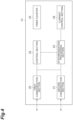
- the control device 13 controls the operation of the inverter 8.
- the control device 13 is a computer system or a processor implemented in an integrated circuit.
- the control device 13 includes a central processing unit (CPU), a read only memory (ROM), a random access memory (RAM), and the like, and an input/output interface and the like.
- the ROM stores various programs or data.
- the control device 13 controls the magnitude of the AC power (AC current) supplied to the feeders 12A and 12B by controlling the inverter 8, thereby controlling the magnitude of power supplied to the overhead transport vehicle 120.
- the power control is performed, for example, using phase shift control.
- phase shift control power control parameters are changed to control the magnitude of an AC power.
- the control section 15 implements phase shift control to change the magnitude (frequency) of the AC power by changing an ON period of the inverter 8.
- the control device 13 uses drive signals to the plurality of switching elements 14 of the inverter 8 to adjust the switching frequency of each switching element 14, and change the ON period of each switching element 14.
- the power control parameter in the phase shift control is the ON period of each switching element 14 of the inverter 8.
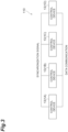
- the first communication section 20 of the sub power supply device stands by in the reception mode and switches to the transmission mode when receiving the query data transmitted from the main power supply device.
- the first communication section 20 transmits the response data created in response to the receipt of the inquiry data to the main power supply device.
- the response data can include data indicating the status and the like of the device (presence or absence of power feed, power on/off).
- the second communication section 21 is in the reception mode for receiving synchronization signals, and receives synchronization signals.
- the second communication section 21 of the sub power supply device receives synchronization signals at intervals of, for example, 100 ⁇ s.
- the second communication section 21 outputs the received synchronization signals to the synchronization processing section 23.
- the control section 22 switches between the main power supply device and the sub power supply device.
- the control section 22 switches between the main power supply device and the sub power supply device based on the presence or absence of power feed and the numbers set for the non-contact power supply devices 1A, 1B, 1C, and 1D.
- a number “1” is set for the non-contact power supply device 1A, "2" for the non-contact power supply device 1B, "3” for the non-contact power supply device 1C, and "4" for the non-contact power supply device 1D.
- the control section 22 switches between main and sub by polling processing for the other non-contact power supply devices 1A, 1B, 1C, and 1D.
- the control section 22 acquires a status of another device through the polling processing and switches between main and sub. Specifically, the control section 22 switches between main and sub based on a polling record and a response record to the polling record.
- the control section 22, when receiving a record of main acceptance from another device switches to the sub power supply device.
- the control section 22 of the other device switches to the main power supply device in response to the transmission of the record of main acceptance.
- control section 22 switches the non-contact power supply devices 1A, 1B, 1C, and 1D between four statuses: main power supply device (power feed), sub power supply device (power feed), main power supply device (standby), and sub power supply device (standby).
- control section 22 of each of the non-contact power supply devices 1A, 1B, 1C, and 1D performs switching so that when the non-contact power supply devices 1A and 1C are on standby (standby without power feed) and the non-contact power supply devices 1B and 1D are during power feeding, the non-contact power supply device 1B will be the main power supply device (power feed) and the non-contact power supply devices 1A, 1C and 1D will be sub power supply devices (standby, power feed).
- control section 22 of each of the non-contact power supply devices 1A, 1B, 1C, and 1D performs switching so that when the non-contact power supply device 1C is on standby and the non-contact power supply devices 1A, 1B, and 1D are during power feeding, the non-contact power supply device 1A will be the main power supply device (power feed) and the non-contact power supply devices 1B, 1C, and 1D will be sub power supply devices (standby, power feed).
- the control section 22 of each device performs switching so that the non-contact power supply device 1A will be the main power supply device (power supply device) and the non-contact power supply device 1B will be a sub power supply device (power feed).
- the control section 22 of each device performs switching so that the non-contact power supply device 1A will be the main power supply device (power feed) and the non-contact power supply device 1B will be a sub power supply device (standby).
- the control section 22 of the non-contact power supply device 1A performs switching so that the non-contact power supply device 1A will be the main power supply device (standby).
- the control section 22 of each device performs switching so that the non-contact power supply device 1A will be the main power supply device (power supply device) and the non-contact power supply device 1B will be a sub power supply device (power feed).
- the control section 22 of each device performs switching so that the non-contact power supply device 1A will be the main power supply device (power feed) and the non-contact power supply device 1B will be a sub power supply device (standby).
- the control section 22 of the non-contact power supply device 1B performs switching so that the non-contact power supply device 1B will be a sub power supply device (power feeding).
- the synchronization processing section 23 synchronizes the carrier cycles of the sub power supply devices based on the synchronization signal transmitted from the main power supply device.
- the synchronization processing section 23 corrects the carrier cycle of the sub power supply device based on the count value of the timer counter 25 and the synchronization signal.
- the timer counter 25 counts at a constant (predetermined) carrier cycle.
- the constant carrier cycle is 9 kHz.
- a predetermined cycle of the carrier cycle is set at 9 kHz.
- the predetermined cycle is not limited to 9 kHz and may be any other frequency.
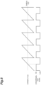
- FIG. 6 is a diagram illustrating the carrier cycle and the synchronization signals in the timer counter 25.
- the carrier cycle is a sawtooth wave.
- the synchronization signal is a square wave.
- the synchronization signal is a U-phase positive-phase signal.
- the synchronization signal is Hi (an example of the first value) when the count value of the timer counter 25 is less than the threshold, and is Low (an example of the second value) when the count value is greater than or equal to the threshold. Hi and Low are 1-bit information.
- the timer counter 25 counts up in one cycle of the synchronization signal.
- the synchronization processing section 23 generates interrupt processing at the timing at which the value of the synchronization signal transmitted from the main power supply device changes, and compares the count value of the timer counter 25 at that timing with the determination value.
- the synchronization processing section 23 stores the determination values.
- the determination value is set arbitrarily by the user.
- the determination value is a value set based on the communication time required for communication between the main power supply device and the sub power supply device and the control delay time for the synchronization processing at the sub power supply device and the threshold.
- the communication time may include a delay time.
- the determination value is set to an intermediate value (threshold) of the carrier cycle as an initial value. The user changes (corrects) the determination value from the initial value by making a predetermined input (operation).
Landscapes
- Engineering & Computer Science (AREA)
- Power Engineering (AREA)
- Computer Networks & Wireless Communication (AREA)
- Charge And Discharge Circuits For Batteries Or The Like (AREA)
- Remote Monitoring And Control Of Power-Distribution Networks (AREA)
- Direct Current Feeding And Distribution (AREA)
- Stand-By Power Supply Arrangements (AREA)
Applications Claiming Priority (2)
| Application Number | Priority Date | Filing Date | Title |
|---|---|---|---|
| JP2022161672 | 2022-10-06 | ||
| PCT/JP2023/029535 WO2024075403A1 (fr) | 2022-10-06 | 2023-08-15 | Système d'alimentation électrique |
Publications (1)
| Publication Number | Publication Date |
|---|---|
| EP4583351A1 true EP4583351A1 (fr) | 2025-07-09 |
Family
ID=90607931
Family Applications (1)
| Application Number | Title | Priority Date | Filing Date |
|---|---|---|---|
| EP23874536.8A Pending EP4583351A1 (fr) | 2022-10-06 | 2023-08-15 | Système d'alimentation électrique |
Country Status (5)
| Country | Link |
|---|---|
| EP (1) | EP4583351A1 (fr) |
| JP (1) | JP7754346B2 (fr) |
| CN (1) | CN119585967A (fr) |
| TW (1) | TW202416640A (fr) |
| WO (1) | WO2024075403A1 (fr) |
Family Cites Families (5)
| Publication number | Priority date | Publication date | Assignee | Title |
|---|---|---|---|---|
| JPS591861U (ja) | 1982-06-29 | 1984-01-07 | 日産自動車株式会社 | アルコ−ルエンジンの始動補助装置 |
| JP4100168B2 (ja) * | 2002-12-25 | 2008-06-11 | 村田機械株式会社 | 給電設備 |
| JP4640035B2 (ja) * | 2005-08-19 | 2011-03-02 | 株式会社ダイフク | 無接触給電設備 |
| JP5398380B2 (ja) * | 2009-06-26 | 2014-01-29 | 三菱電機株式会社 | Pwm半導体電力変換装置システムおよびpwm半導体電力変換装置 |
| IL301875B2 (en) * | 2020-10-06 | 2026-02-01 | Murata Machinery Ltd | Contactless power supply system and transportation system |
-
2023
- 2023-08-15 CN CN202380054954.8A patent/CN119585967A/zh active Pending
- 2023-08-15 EP EP23874536.8A patent/EP4583351A1/fr active Pending
- 2023-08-15 WO PCT/JP2023/029535 patent/WO2024075403A1/fr not_active Ceased
- 2023-08-15 JP JP2024555645A patent/JP7754346B2/ja active Active
- 2023-08-30 TW TW112132720A patent/TW202416640A/zh unknown
Also Published As
| Publication number | Publication date |
|---|---|
| WO2024075403A1 (fr) | 2024-04-11 |
| JPWO2024075403A1 (fr) | 2024-04-11 |
| CN119585967A (zh) | 2025-03-07 |
| TW202416640A (zh) | 2024-04-16 |
| JP7754346B2 (ja) | 2025-10-15 |
Similar Documents
| Publication | Publication Date | Title |
|---|---|---|
| US8836270B2 (en) | Inverter system and communication method | |
| US8400791B2 (en) | Power layer generation of inverter gate drive signals | |
| US9225263B2 (en) | Power layer generation of inverter gate drive signals | |
| US9236814B2 (en) | Parallel inverter device and method for control thereof | |
| EP3358711B1 (fr) | Système de transmission d'énergie sans fil | |
| JP5901861B1 (ja) | 電力変換システム及び電力変換装置 | |
| EP2408099A2 (fr) | Système d'entraînement de moteur comprenant des convertisseurs de puissance montés en parallèle | |
| EP3358712B1 (fr) | Système de transmission de puissance sans fil | |
| US20170093284A1 (en) | Control device of power supply system and power supply unit | |
| US20230211670A1 (en) | Non-contact power supply device, conveying system, and parameter setting method | |
| EP4583351A1 (fr) | Système d'alimentation électrique | |
| US12515562B2 (en) | Non-contact power supply system and transportation system | |
| US6169679B1 (en) | Method and system for synchronizing the phase angles of parallel connected inverters | |
| US20260128620A1 (en) | Power supply system | |
| US6307766B1 (en) | Contactless power system | |
| US11183942B2 (en) | Power conversion apparatus, power conversion system, and method for converting power | |
| EP4283833A1 (fr) | Dispositif de réception d'énergie et système d'alimentation d'énergie sans contact | |
| US11921538B2 (en) | Method for operating at least two inverters connected to a direct current network and motor vehicle | |
| KR102380055B1 (ko) | 인버터 | |
| NL2037352B1 (en) | power converter system | |
| KR20180058483A (ko) | 인버터 장치 |
Legal Events
| Date | Code | Title | Description |
|---|---|---|---|
| STAA | Information on the status of an ep patent application or granted ep patent |
Free format text: STATUS: THE INTERNATIONAL PUBLICATION HAS BEEN MADE |
|
| PUAI | Public reference made under article 153(3) epc to a published international application that has entered the european phase |
Free format text: ORIGINAL CODE: 0009012 |
|
| STAA | Information on the status of an ep patent application or granted ep patent |
Free format text: STATUS: REQUEST FOR EXAMINATION WAS MADE |
|
| 17P | Request for examination filed |
Effective date: 20250402 |
|
| AK | Designated contracting states |
Kind code of ref document: A1 Designated state(s): AL AT BE BG CH CY CZ DE DK EE ES FI FR GB GR HR HU IE IS IT LI LT LU LV MC ME MK MT NL NO PL PT RO RS SE SI SK SM TR |
|
| DAV | Request for validation of the european patent (deleted) | ||
| DAX | Request for extension of the european patent (deleted) |