EP4583370A2 - Machine dynamo-électrique - Google Patents
Machine dynamo-électrique Download PDFInfo
- Publication number
- EP4583370A2 EP4583370A2 EP25177248.9A EP25177248A EP4583370A2 EP 4583370 A2 EP4583370 A2 EP 4583370A2 EP 25177248 A EP25177248 A EP 25177248A EP 4583370 A2 EP4583370 A2 EP 4583370A2
- Authority
- EP
- European Patent Office
- Prior art keywords
- stator
- circuit substrate
- case
- disposed
- dynamo
- Prior art date
- Legal status (The legal status is an assumption and is not a legal conclusion. Google has not performed a legal analysis and makes no representation as to the accuracy of the status listed.)
- Pending
Links
Images


Classifications
-
- H—ELECTRICITY
- H02—GENERATION; CONVERSION OR DISTRIBUTION OF ELECTRIC POWER
- H02K—DYNAMO-ELECTRIC MACHINES
- H02K11/00—Structural association of dynamo-electric machines with electric components or with devices for shielding, monitoring or protection
- H02K11/30—Structural association with control circuits or drive circuits
- H02K11/33—Drive circuits, e.g. power electronics
-
- H—ELECTRICITY
- H02—GENERATION; CONVERSION OR DISTRIBUTION OF ELECTRIC POWER
- H02K—DYNAMO-ELECTRIC MACHINES
- H02K11/00—Structural association of dynamo-electric machines with electric components or with devices for shielding, monitoring or protection
- H02K11/20—Structural association of dynamo-electric machines with electric components or with devices for shielding, monitoring or protection for measuring, monitoring, testing, protecting or switching
- H02K11/25—Devices for sensing temperature, or actuated thereby
-
- H—ELECTRICITY
- H02—GENERATION; CONVERSION OR DISTRIBUTION OF ELECTRIC POWER
- H02K—DYNAMO-ELECTRIC MACHINES
- H02K11/00—Structural association of dynamo-electric machines with electric components or with devices for shielding, monitoring or protection
- H02K11/30—Structural association with control circuits or drive circuits
-
- H—ELECTRICITY
- H02—GENERATION; CONVERSION OR DISTRIBUTION OF ELECTRIC POWER
- H02K—DYNAMO-ELECTRIC MACHINES
- H02K3/00—Details of windings
- H02K3/46—Fastening of windings on the stator or rotor structure
- H02K3/52—Fastening salient pole windings or connections thereto
- H02K3/521—Fastening salient pole windings or connections thereto applicable to stators only
- H02K3/522—Fastening salient pole windings or connections thereto applicable to stators only for generally annular cores with salient poles
-
- H—ELECTRICITY
- H02—GENERATION; CONVERSION OR DISTRIBUTION OF ELECTRIC POWER
- H02K—DYNAMO-ELECTRIC MACHINES
- H02K11/00—Structural association of dynamo-electric machines with electric components or with devices for shielding, monitoring or protection
- H02K11/20—Structural association of dynamo-electric machines with electric components or with devices for shielding, monitoring or protection for measuring, monitoring, testing, protecting or switching
- H02K11/21—Devices for sensing speed or position, or actuated thereby
- H02K11/215—Magnetic effect devices, e.g. Hall-effect or magneto-resistive elements
-
- H—ELECTRICITY
- H02—GENERATION; CONVERSION OR DISTRIBUTION OF ELECTRIC POWER
- H02K—DYNAMO-ELECTRIC MACHINES
- H02K11/00—Structural association of dynamo-electric machines with electric components or with devices for shielding, monitoring or protection
- H02K11/20—Structural association of dynamo-electric machines with electric components or with devices for shielding, monitoring or protection for measuring, monitoring, testing, protecting or switching
- H02K11/21—Devices for sensing speed or position, or actuated thereby
- H02K11/22—Optical devices
Definitions
- the present invention relates to a dynamo-electric machine.
- an inner rotor type brushless DC motor is known in a dynamo-electric machine (refer to, for example, Patent Documents 1 and 2).
- Patent Document 1 discloses a structure in which a resin is injected into a motor case. The resin is filled between a stator and the case to leave a space in a center into which a rotor is inserted.
- Patent Document 2 discloses a structure including a temperature sensor capable of detecting a temperature of a motor.
- the temperature sensor is embedded in a coil formed by winding a winding wire around a stator core.
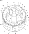
- the case 4 has a bottomed cylindrical shape (a bottomed tubular shape) that accommodates the stator 2.
- the case 4 (the bottomed tubular case) has an open end 41 on one side of the case 4 in the axial direction.
- the case 4 has a bottom portion 42 on the other side of the case 4 in the axial direction.
- the case 4 is made of a metal material such as aluminum.
- the temperature sensor 6 is a positive temperature coefficient (PTC) thermistor.
- the temperature sensor 6 is provided on the end cover 5 side of the stator 2.
- the temperature sensor 6 has a function of rapidly increasing a resistance value when the temperature exceeds a certain level.
- the temperature sensor 6 is electrically connected to each of a motor driving power supply and the circuit substrate 7 (not shown). For example, the resistance value of the temperature sensor 6 increases to stop the power supply to the circuit substrate 7 when the temperature in the vicinity of the temperature sensor 6 becomes equal to or higher than a predetermined value.
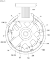
- the temperature sensor 6 is disposed between the bent portions 24a of the winding wires 24 in the adjacent coils 23.
- the temperature sensor 6 is in contact with the bent portions 24a of the winding wires 24.
- the temperature sensor 6 is in contact with the bent portion 24a of each of the winding wires 24 of the two coils 23 (the adjacent coils 23V and 23W in the present embodiment) adjacent to each other in the circumferential direction.
- only one temperature sensor 6 is provided.
- the temperature sensor 6 is disposed between the bent portions 24a of the winding wires 24 in the V-phase coil 23V and the W-phase coil 23W adjacent to each other in the circumferential direction.
- the temperature sensor 6 is brought into contact with each of the bent portions 24a of the adjacent winding wires 24 by a jig (not shown). In this state, a resin is filled in around a contact portion between the bent portion 24a of the winding wire 24 and the temperature sensor 6 by a filling device (not shown). Thus, the temperature sensor 6 can be kept in contact with the bent portion 24a of the winding wire 24.
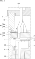
- the circuit substrate 7 controls the driving of the dynamo-electric machine 1. As shown in FIG. 1 , the circuit substrate 7 is disposed inside the case 4 which is inside an outer end of the case 4 in the axial direction. The circuit substrate 7 is supported by a contact portion 82 (which will be described later) which is provided to protrude upward from an upper surface of the first insulator 21. The circuit substrate 7 is disposed at a predetermined distance from the upper surface of the first insulator 21 by the support of the contact portion 82. The circuit substrate 7 is disposed between the stator 2 and the end cover 5. The circuit substrate 7 is disposed inward in the axial direction with respect to the open end 41 on one side of the case 4. The circuit substrate 7 is disposed slightly inward in the axial direction with respect to the case-side annular surface 43a (refer to FIG. 2 ). The circuit substrate 7 is fixed to the inner peripheral surface of the case 4.
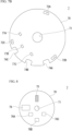
- FIG. 7B is a plan view of an opposite surface (a back surface) of FIG. 7A in the circuit substrate 7.
- the circuit substrate 7 includes magnetic sensors 77A to 77C for detecting a magnetic state (a magnitude and direction of a magnetic field) of the magnet 31.
- the substrate body 70 has a shaft hole 71 coaxial with the axis CL, engaging portions 72A to 72C (substrate-side engaging portions) that engage with the first insulator 21, a connection hole 73 for electrically connecting a cable 100 (refer to FIG. 1 ), and cutout portions 74A to 74C for causing lead wires 25A to 25C (refer to FIG. 3 ) of the coil 23 to pass through.
- the shaft hole 71 has a circular shape.
- the diameter of the shaft hole 71 is larger than an outer diameter of the shaft 11.
- the circuit substrate 7 is disposed outside the shaft 11 in the radial direction at a distance from the shaft 11 (refer to FIG. 1 ).
- each of the engaging portions 72A to 72C has an elongated hole shape that extends in the circumferential direction.
- a plurality of (for example, three in the present embodiment) engaging portions 72A to 72C are provided at intervals in the circumferential direction.
- the three engaging portions 72A to 72C (a first engaging portion 72A, a second engaging portion 72B, and a third engaging portion 72C) are disposed at substantially the same interval in the circumferential direction.
- connection hole 73 has a circular shape.
- a plurality of connection holes 73 (for example, eight in the present embodiment) are provided at intervals in the circumferential direction.
- the eight connection holes 73 are disposed between the first engaging portion 72A and the third engaging portion 72C in the circumferential direction.
- the resistor 75 is a shunt resistor. In the present embodiment, only one resistor 75 is provided.
- the resistor 75 is provided on a surface of the substrate body 70 (the circuit substrate 7) on the end cover 5 side. That is, the resistor 75 is provided on the surface of the substrate body 70 on the side opposite to the surface thereof on the stator 2 side.
- the three FETs 76A to 76C are disposed in the vicinity of the three cutout portions 74A to 74C (the first cutout portion 74A, the second cutout portion 74B and the third cutout portion 74C), respectively.
- Regions 26A to 26C for soldering the lead wires 25A to 25C (refer to FIG. 3 ) of the coil 23 are provided between the three FETs 76A to 76C and the three cutout portions 74A to 74C, respectively.
- the regions 26A to 26C are disposed in the vicinity of the lead wires 25A to 25C of the coil 23. Thus, it is possible to suppress excessive elongation of the lead wires 25A to 25C of the coil 23 and to suppress generation of noise.
- the FETs 76A to 76C are electrically connected to the lead wires 25A to 25C of the coil 23.
- the lead wires 25A to 25C of the coil 23 are soldered in the regions 26A to 26C and then electrically connected to the FETs 76A to 76C by a wiring formed on the circuit substrate 7. Since the FETs 76A to 76C are disposed in the vicinity of the regions 26A to 26C, the wiring on the circuit substrate 7 can be shortened and simplified.
- the magnetic sensors 77A to 77C are Hall elements.
- a plurality of (for example, three in the present embodiment) magnetic sensors 77A to 77C are provided at intervals in the circumferential direction.
- the magnetic sensors 77A to 77C are provided on the surface of the substrate body 70 on the stator 2 side (the surface in FIG. 7B ).
- each of the three magnetic sensors 77A to 77C detects a change in magnetic flux due to the rotation of the magnet 31 with a magnetic sensor placed at a specific position on the substrate body 70 on the stationary side.
- the magnetic sensor may be directly above the magnet 31 when seen in a plan view and may be disposed close to the magnet 31 in the axial direction.
- rotation detection sensitivity of the magnet 31 can be improved.
- the encoder 78 is an optical encoder that uses an infrared light emitting diode (IR LED) as a light emitting element.
- the encoder 78 detects rotation of a disk (a disk having a slit hole) for a detector (not shown) mounted on the shaft 11 and generates an on/off signal of light.
- IR LED infrared light emitting diode
- the encoder 78 detects rotation of a disk (a disk having a slit hole) for a detector (not shown) mounted on the shaft 11 and generates an on/off signal of light.
- only one encoder 78 is provided.
- the encoder 78 has the largest installation area among the electronic components provided on the circuit substrate 7.
- the encoder 78 is provided on the end cover 5 side of the substrate main body 70.
- the encoder 78 is disposed between the first FET 76A located on the leftmost side among the three FETs 76A to 76C and the resistor 75. That is, the encoder 78 is disposed between the first FET 76A and the resistor 75 in the circumferential direction.
- the resistor 75 is disposed on the side opposite to the second FET 76B with the shaft hole 71 interposed therebetween.
- holes other than the shaft hole 71 of the substrate body 70, cutout portions, and the like are not shown.
- the first insulation sheet 8 is disposed between the stator 2 and the rotor 3 and the circuit substrate 7.
- the first insulation sheet 8 insulates at least the circuit substrate 7 and the coil 23.
- the first insulation sheet 8 has an annular shape when seen in the axial direction.
- the first insulation sheet 8 has an inner peripheral edge portion that forms an insertion hole through which the shaft 11 is inserted in a central portion thereof.
- the inner peripheral edge portion of the first insulation sheet 8 is disposed outside the shaft 11 at a distance from the shaft 11 in the radial direction.
- the first insulation sheet 8 allows the shaft 11 to rotate.
- the first insulation sheet 8 is supported by the first insulator 21. Specifically, the first insulation sheet 8 is supported by a plurality of contact portions 81 (which will be described later) provided on the first insulator 21.
- the second insulation sheet 9 is disposed between the circuit substrate 7 and the end cover 5.
- the second insulation sheet 9 is disposed at a position adjacent to the circuit substrate 7.
- the second insulation sheet 9 insulates at least the circuit substrate 7 and the end cover 5.
- the second insulation sheet 9 has an annular shape larger than the first insulation sheet 8 when seen in the axial direction.
- the second insulation sheet 9 has an inner peripheral edge portion that forms an insertion hole through which the shaft 11 is inserted in a central portion thereof.
- the inner peripheral edge portion of the second insulation sheet 9 is disposed outside the shaft 11 at a distance from the shaft 11 in the radial direction.
- the second insulation sheet 9 allows the shaft 11 to rotate.
- the second insulation sheet 9 is slightly separated from the surface of the circuit substrate 7 on the end cover 5 side in the axial direction. Additional insulation between the circuit substrate 7 and the end cover 5 is ensured by providing a gap between the surface of the circuit substrate 7 on the end cover 5 side and the second insulation sheet 9.
- Each of the first insulation sheet 8 and the second insulation sheet 9 is a sheet having both insulating properties and flame retardancy.
- Each of the first insulation sheet 8 and the second insulation sheet 9 is formed of aramid fibers.
- each of the first insulation sheet 8 and the second insulation sheet 9 is an insulating paper.
- Each of the first insulation sheet 8 and the second insulation sheet 9 has a thickness of 0.25 mm or more.
- each of the first insulation sheet 8 and the second insulation sheet 9 has a thickness of 0.25 mm or more and 0.35 mm or less.
- the resin sheet 10 is made of silicone.
- the resin sheet 10 has a thickness of 0.2 mm or more.
- the resin sheet 10 has a thickness of 0.2 mm or more and 0.3 mm or less.
- the resin sheet 10 has a thermal conductivity of 1.0 W/m ⁇ K or more and 1.4 W/m ⁇ K or less at a load of 20 psi in a measuring method based on ASTM D5470.
- the resin sheet 10 has V-0 in the UL94 standard which is a standard indicating a degree of incombustibility of a material.
- the first insulator 21 has an annular portion 80 coaxial with the stator core 20, a contact portion 81 (hereinafter, also referred to as “sheet-side contact portion 81") that comes into contact with a surface of the first insulation sheet 8 on the stator 2 side, a contact portion 82 (hereinafter, also referred to as “substrate-side contact portion 82") that comes into contact with a surface of the circuit substrate 7 on the stator 2 side, a plurality of extending portions 83 (refer to FIG. 6 ) that extend toward the surface of the circuit substrate 7 on the stator 2 side, and engaging portions 84A to 84C (refer to FIG. 5 ) that engage with the circuit substrate 7 through each of the plurality of engaging portions 72A to 72C of the circuit substrate 7.
- the sheet-side contact portion 81 extends from the inner peripheral side of the annular portion 80 toward one side in the axial direction. A tip end of the sheet-side contact portion 81 is in contact with the surface of the first insulation sheet 8 on the stator 2 side.
- a plurality of (for example, nine in the present embodiment) sheet-side contact portions 81 are provided at intervals in the circumferential direction (refer to FIG. 6 ). The nine sheet-side contact portions 81 are disposed at substantially the same interval in the circumferential direction (refer to FIG. 6 ).
- the substrate-side contact portion 82 extends from the outer peripheral side of the annular portion 80 toward one side in the axial direction. A tip end of the substrate-side contact portion 82 is in contact with the surface of the circuit substrate 7 on the stator 2 side.
- the substrate-side contact portion 82 extends toward one side in the axial direction longer than each of the sheet-side contact portion 81 and the extending portion 83 (refer to FIG. 6 ).
- a plurality of (for example, eleven in the present embodiment) substrate-side contact portions 82 are provided at intervals in the circumferential direction (refer to FIG. 6 ).
- the extending portion 83 extends from the outer peripheral side of the annular portion 80 toward one side in the axial direction.
- a plurality of (for example, four in the present embodiment) extending portions 83 are provided at intervals in the circumferential direction.
- a tip end of the extending portion 83 is separated from the surface of the circuit substrate 7 on the stator 2 side. That is, the extending portion 83 is not in contact with the circuit substrate 7.
- a gap is formed between the tip end of the extending portion 83 and the surface of the circuit substrate 7 on the stator 2 side.
- the gap between the tip end of the extending portion 83 and the circuit substrate 7 is a gap for a space in which a wiring part 1001 is accommodated when the wiring part 1001 (refer to FIG.
- the gap serves as a clearance for the protruding wiring part 1001 as described below.
- the wiring part 1001 is soldered to the circuit substrate 7 in a state in which the wiring part 1001 is inserted through the connection hole 73. Then, the wiring part 1001 and the solder protrude from the surface of the circuit substrate 7 on the stator 2 side to the stator 2 side.
- a gap is provided as the clearance for the protruding wiring part 1001.
- the engaging portions 84A to 84C extend from the outer peripheral side of the annular portion 80 to one side in the axial direction.
- the engaging portions 84A to 84C extend to one side in the axial direction to be longer than the substrate-side contact portion 82.
- Each of the engaging portions 84A to 84C has a hook shape that can be engaged with the circuit substrate 7 (refer to FIG. 5 ).
- the engaging portions 84A to 84C extend from the annular portion 80 to one side in the axial direction and are then bent outward in the radial direction. Thus, the engaging portions 84A to 84C make it possible to maintain an engaged state with the circuit substrate 7.
- a plurality of (for example, three in the present embodiment) engaging portions 84A to 84C are provided at intervals in the circumferential direction.
- the three engaging portions 84A to 84C (a first engaging portion 84A, a second engaging portion 84B, and a third engaging portion 84C) are disposed at substantially the same interval in the circumferential direction.
- the three engaging portions 84A to 84C (the first engaging portion 84A, the second engaging portion 84B, and the third engaging portion 84C) engage with the circuit substrate 7 through the three engaging portions 72A to 72C (the first engaging portion 72A, the second engaging portion 72B, and the third engaging portion 72C), respectively (refer to FIG. 5 ).
- the eleven substrate-side contact portions 82 include five substrate-side contact portions 82 disposed between the first engaging portion 84A and the second engaging portion 84B in the circumferential direction, five substrate-side contact portions 82 disposed between the second engaging portion 84B and the third engaging portion 84C in the circumferential direction, and one substrate-side contact portion 82 disposed between the first engaging portion 84A and the third engaging portion 84C in the circumferential direction.
- the four extending portions 83 are disposed between the first engaging portion 84A and the third engaging portion 84C in the circumferential direction.
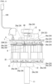
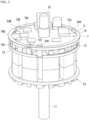
- a filling step of filling the case 4 with the resin 90 is performed by the following procedure.
- the temperature sensor 6 is brought into contact with the bent portion 24a of the coil 23 using a jig (not shown), and the lead wire 60 of the temperature sensor 6 is exposed to the outside. Then, in this state, the case 4 is filled with the resin 90 (refer to FIG. 4 ). Thus, the case 4, the stator 2, and the temperature sensor 6 are integrated with the resin 90. Then, the lead wire 60 passes through a slit (not shown) of the circuit substrate 7 and is soldered to the circuit substrate 7. In this way, a wiring step of connecting the lead wire 60 to the circuit substrate 7 is performed.
- the resin 90 fills the other gaps in the case 4 in a state in which a space 91 in which the shaft 11 and the rotor 3 are inserted is left in the central portion.
- the resin 90 is a thermosetting resin such as an epoxy resin.
- the resin 90 is filled in the case 4 to a position at which the coil 23 (refer to FIG. 1 ) is not exposed in the axial direction.
- the resin 90 has a thermal conductivity of 0.1 W/m ⁇ K or more and 0.9 W/m ⁇ K or less at a load of 20 psi in a measuring method based on ASTM D5470.
- the resin 90 has V-0 in UL94 standard which is a standard indicating a degree of incombustibility of the material.
- a low volume efficiency in an environment of 25 °C is 1 ⁇ 10 15 ⁇ cm
- a volume low efficiency in an environment of 100 °C is 1 ⁇ 10 15 ⁇ cm
- a volume low efficiency in an environment of 150 °C is 3 ⁇ 10 13 ⁇ cm in a measuring method based on ASTM D257.
- the resin sheet 10 is placed in the case 4 (a sheet arrangement step).
- stator 2 is placed in the case 4 (a stator arrangement step).
- the temperature sensor 6 is disposed between the bent portions 24a of the adjacent coils 23 using a jig (not shown) in a state in which the temperature sensor 6 is in contact with the bent portions 24a of the adjacent coils 23 (a second filling preparation step).
- the resin 90 is filled between an inner peripheral surface of the case 4 and an outer peripheral surface of the mold material using a filling device (not shown) (a resin filling step).
- the case 4 filled with the resin 90 is placed in a vacuum chamber and then evacuated to remove (degas) air bubbles contained in the filled resin 90 (a filling finish step).
- the mold material is taken out (a filling completion step).
- the space 91 in which the rotor 3 is inserted is formed in the case 4 filled with the resin 90.
- the dynamo-electric machine 1 includes the tubular stator 2, the rotor 3 disposed in the internal space of the stator 2, the bottomed tubular case 4 that accommodates the stator 2, the end cover 5 mounted on the open end 41 of the case 4 on one side, and the temperature sensor 6, wherein the stator 2 includes the stator core 20 having the plurality of protruding portions 20b that protrude toward the center of the stator 2, the insulators 21 and 22 mounted on the stator core 20, and the coil 23 formed by winding the winding wire 24 around each of the plurality of protruding portions 20b with the insulators 21 and 22 therebetween, and the temperature sensor 6 is disposed on the end cover 5 side of the stator 2 between the bent portions 24a of the winding wires 24 in the adjacent coils 23.
- the temperature sensor 6 is disposed on the end cover 5 side of the stator 2 between the bent portions 24a of the winding wires 24 in the adjacent coils 23, it is possible to detect the temperature of the bent portion 24a which is most likely to generate heat in the dynamo-electric machine 1.
- the driving of the dynamo-electric machine 1 can be optimally operated based on detection results of the temperature sensor 6 (the temperature of the bent portion 24a of the winding wire 24 in the coil 23 of the dynamo-electric machine 1). Therefore, it is possible to suppress problems due to the heat generation of the dynamo-electric machine 1 using the temperature sensor 6.
- the circuit substrate 7 that controls driving of the dynamo-electric machine 1 is further provided.
- the circuit substrate 7 is disposed in the case 4 and is disposed between the stator 2 and the end cover 5, and thus the following effects can be obtained.
- the circuit substrate 7 As compared with a case in which the circuit substrate 7 is disposed outside the case 4 (inside the end cover 5), the circuit substrate 7 can be easily assembled. Therefore, the dynamo-electric machine 1 can be assembled efficiently.
- the resin sheet 10 having a higher thermal conductivity than the resin is disposed between the bottom portion 42 of the case 4 and the stator 2, when the bottom portion 42 of the case 4 is mounted on the mounting member 101, it is possible to promote heat conduction (heat dissipation) of heat generated from the coil 23 to the mounting member 101 and to suppress the temperature rise of the dynamo-electric machine 1 (the coil 23). Further, due to the resin sheet 10, it is possible to ensure the insulating property between the bottom portion 42 of the case 4 and the stator 2 disposed in the case 4.
- the circuit substrate 7 since the circuit substrate 7 has the resistor 75 for detecting a current supplied to the coil 23, and the resistor 75 is disposed on the surface of the circuit substrate 7 on the end cover 5 side, the following effects are obtained.
- the circuit substrate 7 further includes the plurality of FETs 76A to 76C and the encoder 78, and the encoder 78 is disposed between the first FET 76A located on the leftmost side among the plurality of FETs 76A to 76C and the resistor 75 in a plan view, the following effects are obtained.
- the resin 90 is filled in the gap between the case 4 and the stator 2 arranged in the case 4, insulation is ensured by covering the coil 23 of the stator 2 with the resin 90, and further insulation can be ensured by the first insulation sheet 8. Also, since the circuit substrate 7 and the end cover 5 are insulated by the second insulation sheet 9, the end cover 5 made of a metal material can be used, and it is possible to realize electromagnetic compatibility (EMC) and to enhance a heat dissipation effect.
- EMC electromagnetic compatibility
- the first insulation sheet 8 can be supported in the axial direction by the sheet-side contact portion 81.
- the second insulation sheet 9 has the following effects by being sandwiched between the opening portion of the case 4 on one side and the tip end of the cylindrical portion 50 of the end cover 5.
- first insulation sheet 8 and the second insulation sheet 9 excellent withstand voltage characteristics (for example, a withstand voltage of 5000 V in UL standard) can be obtained.
- the magnetic sensors 77A to 77C can be brought closer to the rotor 3 as compared with a case in which the magnetic sensors 77A to 77C are provided on the end cover 5 side of the circuit board 7, the detection accuracy of the magnetic sensors 77A to 77C can be improved.
- the first insulation sheet 8 when the first insulation sheet 8 is provided between the circuit substrate 7 and the stator 2, the first insulation sheet 8 can insulate the coil 23 from the magnetic sensors 77A to 77C.
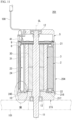
- a dynamo-electric machine 201 includes a tubular case 204, a front cover 215 mounted on an open end 245 of the tubular case 204 on the other side, and a resin sheet 10 disposed between the front cover 215 and the stator 2.
- the tubular case 204 has a larger length in the axial direction than the bottomed tubular case 4 (refer to FIG. 1 ) of the first embodiment.
- the tubular case 204 has a second stepped portion 246 at a portion on the other side in the axial direction.
- the second stepped portion 246 has an annular surface 246a (hereinafter, also referred to as "second case-side annular surface 246a”) having an annular shape when seen in the axial direction, and a peripheral surface 246b (hereinafter, also referred to as "second case-side peripheral surface 246b”) that extends from an outer peripheral edge of the second case-side annular surface 246a to the other side in the axial direction.
- a length of the second case-side peripheral surface 246b in the axial direction is larger than a length of the second case-side annular surface 246a in the radial direction.
- a portion of the front cover 215 on the other side is mounted on a mounting member 101 made of a metal plate material such as aluminum.
- the other surface of the front cover 215 is a mounting surface for the mounting member 101.
- the front cover 215 is mounted on the open end 245 of the tubular case 204 on the other side in the axial direction.
- the front cover 215 is made of a metal material such as aluminum.
- the front cover 215 has an annular surface 215a (hereinafter, also referred to as “front cover-side annular surface 215a”) having an annular shape when seen in the axial direction, and a peripheral surface 215b (hereinafter, also referred to as "front cover-side peripheral surface 215b”) that extends from an outer peripheral edge of the front cover-side annular surface 215a to the other side in the axial direction.
- a length of the front cover-side annular surface 215a in the radial direction is larger than a length of the second case-side annular surface 246a in the radial direction.
- a length of the front cover-side peripheral surface 215b in the axial direction is smaller than a length of the second case-side peripheral surface 246b in the axial direction.
- a length of the front cover-side peripheral surface 215b in the axial direction is smaller than a length of the front cover-side annular surface 215a in the radial direction.
- the front cover 215 is mounted on the open end 245 on the other side of the tubular case 204 by fitting an outer peripheral portion of the front cover 215 on one side in the axial direction to the second stepped portion 246 of the tubular case 204.
- the front cover-side peripheral surface 215b is in contact with the second case-side peripheral surface 246b.
- the front cover-side annular surface 215a is separated from the second case-side annular surface 246a in the axial direction.
- the resin sheet 10 is disposed between the front cover 215 and the stator 2.
- the resin sheet 10 is disposed between the front cover 215 and the second insulator 22.
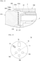
- an annular convex portion 217 that has an annular shape and is in contact with an inner peripheral edge of the insertion hole of the resin sheet 10 is provided on the bottom portion 216 of the front cover 215.
- a height of the annular convex portion 217 in the axial direction is slightly larger than a thickness of the resin sheet 10.
- an inner diameter of the insertion hole of the resin sheet 10 is designed to match an outer diameter of the annular convex portion 217.
- the constitution for suppressing the misalignment of the resin sheet 10 is not limited to the providing of the annular convex portion 217.
- the outer diameter of the resin sheet 10 may be adjusted to the inner diameter of the tubular case 204.
- a position of the second insulator 22 in the axial direction is determined by the second insulator 22 coming into contact with the annular convex portion 217. Therefore, in the axial direction, the resin sheet 10 is separated from the second insulator 22.
- the present invention is not limited thereto, and the resin sheet 10 may be in contact with the second insulator 22.
- case 204 is the tubular case having a tubular shape and includes the front cover 215 mounted on the open end 245 of the tubular case 204 on the other side, and the resin sheet 10 disposed between the front cover 215 and the stator 2, the following effects are obtained.
- the front cover 215 When the front cover 215 is mounted on the mounting member 101 by arranging the resin sheet 10 having a higher thermal conductivity than the resin between the front cover 215 and the stator 2, it is possible to promote heat conduction (heat dissipation) of heat generated from the coil 23 to the mounting member 101 and to suppress the temperature rise of the dynamo-electric machine 201 (the coil 23). Further, the insulating property between the front cover 215 and the stator 2 disposed in the case 204 can be ensured by the resin sheet 10.
- the resistor 75 may be disposed between the first FET 76A located on the leftmost side among the plurality of FETs 76A to 76C and the encoder 78. That is, the resistor 75 is disposed between the first FET 76A and the encoder 78 in the circumferential direction.
- the resistor 75 in a plan view, is disposed on the side opposite to the third FET 76C with the shaft hole 71 interposed therebetween.
- the encoder 78 is disposed on the side opposite to the second FET 76B with the shaft hole 71 interposed therebetween in a plan view.
Landscapes
- Engineering & Computer Science (AREA)
- Power Engineering (AREA)
- Microelectronics & Electronic Packaging (AREA)
- Permanent Magnet Type Synchronous Machine (AREA)
- Iron Core Of Rotating Electric Machines (AREA)
- Connection Of Motors, Electrical Generators, Mechanical Devices, And The Like (AREA)
Applications Claiming Priority (3)
| Application Number | Priority Date | Filing Date | Title |
|---|---|---|---|
| JP2020062082A JP7478010B2 (ja) | 2020-03-31 | 2020-03-31 | 回転電機 |
| PCT/JP2021/012696 WO2021200591A1 (fr) | 2020-03-31 | 2021-03-25 | Moteur rotatif |
| EP21777930.5A EP4131745A4 (fr) | 2020-03-31 | 2021-03-25 | Moteur rotatif |
Related Parent Applications (1)
| Application Number | Title | Priority Date | Filing Date |
|---|---|---|---|
| EP21777930.5A Division EP4131745A4 (fr) | 2020-03-31 | 2021-03-25 | Moteur rotatif |
Publications (2)
| Publication Number | Publication Date |
|---|---|
| EP4583370A2 true EP4583370A2 (fr) | 2025-07-09 |
| EP4583370A3 EP4583370A3 (fr) | 2025-09-24 |
Family
ID=77929346
Family Applications (2)
| Application Number | Title | Priority Date | Filing Date |
|---|---|---|---|
| EP25177248.9A Pending EP4583370A3 (fr) | 2020-03-31 | 2021-03-25 | Machine dynamo-électrique |
| EP21777930.5A Pending EP4131745A4 (fr) | 2020-03-31 | 2021-03-25 | Moteur rotatif |
Family Applications After (1)
| Application Number | Title | Priority Date | Filing Date |
|---|---|---|---|
| EP21777930.5A Pending EP4131745A4 (fr) | 2020-03-31 | 2021-03-25 | Moteur rotatif |
Country Status (6)
| Country | Link |
|---|---|
| US (1) | US12289019B2 (fr) |
| EP (2) | EP4583370A3 (fr) |
| JP (1) | JP7478010B2 (fr) |
| CN (1) | CN115298941A (fr) |
| TW (1) | TWI783422B (fr) |
| WO (1) | WO2021200591A1 (fr) |
Families Citing this family (2)
| Publication number | Priority date | Publication date | Assignee | Title |
|---|---|---|---|---|
| JP7719692B2 (ja) * | 2021-10-28 | 2025-08-06 | ニデック株式会社 | モータ |
| KR102718864B1 (ko) * | 2022-12-23 | 2024-10-16 | 주식회사 현대케피코 | 전기 모터 |
Citations (3)
| Publication number | Priority date | Publication date | Assignee | Title |
|---|---|---|---|---|
| JP3318531B2 (ja) | 1998-08-04 | 2002-08-26 | ミネベア株式会社 | 回転電機及びその軸受構造 |
| JP3612715B2 (ja) | 1996-03-07 | 2005-01-19 | セイコーエプソン株式会社 | モータ及びその製造方法 |
| JP2020062082A (ja) | 2018-10-15 | 2020-04-23 | 住友ゴム工業株式会社 | 表面改質方法及び注射器用ガスケット |
Family Cites Families (34)
| Publication number | Priority date | Publication date | Assignee | Title |
|---|---|---|---|---|
| JPS5869294A (ja) | 1981-10-21 | 1983-04-25 | Neos Co Ltd | 燃料油用添加剤 |
| JPH0326782Y2 (fr) * | 1985-12-11 | 1991-06-10 | ||
| JP3821341B2 (ja) | 1998-08-24 | 2006-09-13 | 株式会社デンソー | 温度センサ付き回転電機 |
| CN2445503Y (zh) * | 2000-09-27 | 2001-08-29 | 谢孟哲 | 交流风扇定子线圈绝缘片 |
| JP4660932B2 (ja) * | 2001-01-26 | 2011-03-30 | パナソニック株式会社 | モータ駆動装置 |
| US7180212B2 (en) | 2004-07-02 | 2007-02-20 | Visteon Global Technologies, Inc. | Electric machine with integrated electronics in a circular/closed-loop arrangement |
| JP2006340580A (ja) | 2005-06-06 | 2006-12-14 | Toyota Motor Corp | 回転電機 |
| JP2008022679A (ja) * | 2006-07-14 | 2008-01-31 | Toyota Motor Corp | 温度検出素子の固定構造および回転電機の製造方法 |
| JP5019960B2 (ja) | 2007-06-11 | 2012-09-05 | 三洋電機株式会社 | モータ及びモータの製造方法 |
| KR100903519B1 (ko) * | 2007-09-18 | 2009-06-19 | 주식회사 아모텍 | 영구자석 매입형 모터 및 이를 이용한 공기흡입장치 |
| CN101588096B (zh) * | 2008-05-23 | 2013-04-10 | 乐金电子(天津)电器有限公司 | 电机 |
| JP5257017B2 (ja) | 2008-11-25 | 2013-08-07 | パナソニック株式会社 | 電動機及びそれを搭載した送風装置 |
| JP5396842B2 (ja) | 2008-12-09 | 2014-01-22 | トヨタ自動車株式会社 | 回転電機と回転電機の製造方法 |
| JP2010259271A (ja) * | 2009-04-27 | 2010-11-11 | Sanyo Electric Co Ltd | 電動モータ及び電動車輌 |
| JP2010273514A (ja) | 2009-05-25 | 2010-12-02 | Toyota Motor Corp | ステータ |
| JP5039171B2 (ja) | 2010-05-11 | 2012-10-03 | 三菱電機株式会社 | 電動式駆動装置およびその電動式駆動装置を搭載した電動式パワーステアリング装置 |
| JP5075941B2 (ja) * | 2010-05-18 | 2012-11-21 | パナソニックEsパワーツール株式会社 | ブラシ付モータにおける温度センサの取付構造及び電動工具 |
| JP2013153544A (ja) | 2010-08-20 | 2013-08-08 | Nippon Densan Corp | モータ |
| JP2012060811A (ja) * | 2010-09-10 | 2012-03-22 | Nippon Densan Corp | モータ |
| JP5586707B2 (ja) * | 2010-12-07 | 2014-09-10 | 三菱電機株式会社 | 電力変換回路内蔵モーター、この電力変換回路内蔵モーターを搭載した流体ポンプ、この流体ポンプを搭載した空気調和機、給湯器、電力変換回路内蔵モーターを搭載した機器 |
| US20140265661A1 (en) | 2013-03-14 | 2014-09-18 | Remy Technologies, Llc | Sheet metal cooling jacket with baffles |
| JP5827288B2 (ja) * | 2013-09-13 | 2015-12-02 | トヨタ自動車株式会社 | サーミスタモジュール |
| JP6221804B2 (ja) * | 2014-02-13 | 2017-11-01 | トヨタ自動車株式会社 | 回転電機のステータ |
| JP6281373B2 (ja) | 2014-03-28 | 2018-02-21 | 株式会社富士通ゼネラル | 電動機 |
| DE102015006345A1 (de) * | 2014-05-20 | 2015-11-26 | Schaeffler Technologies AG & Co. KG | Elektrische Maschine mit Temperatursensor |
| JP6179476B2 (ja) | 2014-07-31 | 2017-08-16 | 株式会社デンソー | 駆動装置、および、これを用いた電動パワーステアリング装置 |
| DE102015203435B4 (de) * | 2015-02-26 | 2023-07-20 | Schaeffler Technologies AG & Co. KG | Elektrische Maschine mit Temperatursensor und Stator sowie Verfahren zur Herstellung eines Stators |
| JP6648492B2 (ja) * | 2015-11-04 | 2020-02-14 | 株式会社デンソー | 電子装置 |
| JP6651545B2 (ja) | 2015-12-09 | 2020-02-19 | 日本電産テクノモータ株式会社 | モータ |
| JP6549480B2 (ja) * | 2015-12-28 | 2019-07-24 | トヨタ自動車株式会社 | 電動機用ステータ |
| WO2018138852A1 (fr) | 2017-01-27 | 2018-08-02 | 株式会社日立産機システム | Machine électrique tournante |
| JP6272525B1 (ja) * | 2017-04-21 | 2018-01-31 | 三菱電機株式会社 | 回転電機 |
| JP2019075872A (ja) | 2017-10-13 | 2019-05-16 | 株式会社ジェイテクト | 制御機能付きアクチュエータ及び電動ポンプ |
| JP7063573B2 (ja) | 2017-10-30 | 2022-05-09 | ミネベアミツミ株式会社 | モータ |
-
2020
- 2020-03-31 JP JP2020062082A patent/JP7478010B2/ja active Active
-
2021
- 2021-03-25 US US17/905,203 patent/US12289019B2/en active Active
- 2021-03-25 WO PCT/JP2021/012696 patent/WO2021200591A1/fr not_active Ceased
- 2021-03-25 EP EP25177248.9A patent/EP4583370A3/fr active Pending
- 2021-03-25 EP EP21777930.5A patent/EP4131745A4/fr active Pending
- 2021-03-25 CN CN202180021935.6A patent/CN115298941A/zh active Pending
- 2021-03-26 TW TW110111067A patent/TWI783422B/zh active
Patent Citations (3)
| Publication number | Priority date | Publication date | Assignee | Title |
|---|---|---|---|---|
| JP3612715B2 (ja) | 1996-03-07 | 2005-01-19 | セイコーエプソン株式会社 | モータ及びその製造方法 |
| JP3318531B2 (ja) | 1998-08-04 | 2002-08-26 | ミネベア株式会社 | 回転電機及びその軸受構造 |
| JP2020062082A (ja) | 2018-10-15 | 2020-04-23 | 住友ゴム工業株式会社 | 表面改質方法及び注射器用ガスケット |
Also Published As
| Publication number | Publication date |
|---|---|
| TWI783422B (zh) | 2022-11-11 |
| CN115298941A (zh) | 2022-11-04 |
| EP4583370A3 (fr) | 2025-09-24 |
| US20230113985A1 (en) | 2023-04-13 |
| JP7478010B2 (ja) | 2024-05-02 |
| WO2021200591A1 (fr) | 2021-10-07 |
| EP4131745A4 (fr) | 2024-04-24 |
| JP2021164227A (ja) | 2021-10-11 |
| US12289019B2 (en) | 2025-04-29 |
| TW202141918A (zh) | 2021-11-01 |
| EP4131745A1 (fr) | 2023-02-08 |
Similar Documents
| Publication | Publication Date | Title |
|---|---|---|
| US10263499B2 (en) | Motor | |
| JP4246068B2 (ja) | 固定子と回転子との心合わせを可能にするハウジングを有するブラシレスモータ | |
| US7898126B2 (en) | Inverter-integrated rotating electric machine having improved thermal characteristics | |
| US20200195083A1 (en) | Rotating electrical device | |
| US20220029498A1 (en) | Busbar unit for motor | |
| US7498701B2 (en) | Controller-integrated rotating electrical machine | |
| CN101478216B (zh) | 内转子无刷电动机 | |
| JP2021513831A (ja) | 電気モータ並びに電気モータを製造するための方法 | |
| EP4583370A2 (fr) | Machine dynamo-électrique | |
| US11527940B2 (en) | Motor | |
| US12355326B2 (en) | Dynamo-electric machine | |
| US11043881B2 (en) | Component-mounting device and electronic apparatus | |
| US20200235646A1 (en) | Component-mounting device and electronic apparatus | |
| JP5748698B2 (ja) | 電動機 | |
| US20220140705A1 (en) | Electrical machine with an integrated measurement printed circuit board | |
| WO2022209766A1 (fr) | Moteur | |
| JP2020088990A (ja) | ステータユニット、モータ及びファンモータ | |
| JP2013219915A (ja) | 電動機及び換気扇 | |
| JP2012253846A (ja) | 電動機および換気扇 | |
| CN113949200B (zh) | 马达和电气产品 | |
| JP7239333B2 (ja) | モータ | |
| HK1101993B (en) | Rotating electric machine and flat motor with magnetic transducer in both | |
| JP2018121490A (ja) | 制御装置一体型回転電機 | |
| HK1101993A1 (en) | Rotating electric machine and flat motor with magnetic transducer in both |
Legal Events
| Date | Code | Title | Description |
|---|---|---|---|
| PUAI | Public reference made under article 153(3) epc to a published international application that has entered the european phase |
Free format text: ORIGINAL CODE: 0009012 |
|
| STAA | Information on the status of an ep patent application or granted ep patent |
Free format text: STATUS: REQUEST FOR EXAMINATION WAS MADE |
|
| 17P | Request for examination filed |
Effective date: 20250522 |
|
| AC | Divisional application: reference to earlier application |
Ref document number: 4131745 Country of ref document: EP Kind code of ref document: P |
|
| AK | Designated contracting states |
Kind code of ref document: A2 Designated state(s): AL AT BE BG CH CY CZ DE DK EE ES FI FR GB GR HR HU IE IS IT LI LT LU LV MC MK MT NL NO PL PT RO RS SE SI SK SM TR |
|
| REG | Reference to a national code |
Ref country code: DE Ref legal event code: R079 Free format text: PREVIOUS MAIN CLASS: H02K0003520000 Ipc: H02K0011250000 |
|
| PUAL | Search report despatched |
Free format text: ORIGINAL CODE: 0009013 |
|
| AK | Designated contracting states |
Kind code of ref document: A3 Designated state(s): AL AT BE BG CH CY CZ DE DK EE ES FI FR GB GR HR HU IE IS IT LI LT LU LV MC MK MT NL NO PL PT RO RS SE SI SK SM TR |
|
| RIC1 | Information provided on ipc code assigned before grant |
Ipc: H02K 11/25 20160101AFI20250819BHEP Ipc: H02K 11/33 20160101ALI20250819BHEP Ipc: H02K 3/52 20060101ALI20250819BHEP |