EP4583607A1 - Procédé et appareil de communication - Google Patents
Procédé et appareil de communication Download PDFInfo
- Publication number
- EP4583607A1 EP4583607A1 EP23887863.1A EP23887863A EP4583607A1 EP 4583607 A1 EP4583607 A1 EP 4583607A1 EP 23887863 A EP23887863 A EP 23887863A EP 4583607 A1 EP4583607 A1 EP 4583607A1
- Authority
- EP
- European Patent Office
- Prior art keywords
- time domain
- unit
- type
- frequency domain
- resource
- Prior art date
- Legal status (The legal status is an assumption and is not a legal conclusion. Google has not performed a legal analysis and makes no representation as to the accuracy of the status listed.)
- Pending
Links
Images


Classifications
-
- H—ELECTRICITY
- H04—ELECTRIC COMMUNICATION TECHNIQUE
- H04L—TRANSMISSION OF DIGITAL INFORMATION, e.g. TELEGRAPHIC COMMUNICATION
- H04L5/00—Arrangements affording multiple use of the transmission path
- H04L5/003—Arrangements for allocating sub-channels of the transmission path
- H04L5/0044—Allocation of payload; Allocation of data channels, e.g. PDSCH or PUSCH
-
- H—ELECTRICITY
- H04—ELECTRIC COMMUNICATION TECHNIQUE
- H04L—TRANSMISSION OF DIGITAL INFORMATION, e.g. TELEGRAPHIC COMMUNICATION
- H04L5/00—Arrangements affording multiple use of the transmission path
- H04L5/0001—Arrangements for dividing the transmission path
- H04L5/0003—Two-dimensional division
- H04L5/0005—Time-frequency
-
- H—ELECTRICITY
- H04—ELECTRIC COMMUNICATION TECHNIQUE
- H04L—TRANSMISSION OF DIGITAL INFORMATION, e.g. TELEGRAPHIC COMMUNICATION
- H04L5/00—Arrangements affording multiple use of the transmission path
- H04L5/003—Arrangements for allocating sub-channels of the transmission path
- H04L5/0053—Allocation of signalling, i.e. of overhead other than pilot signals
- H04L5/0055—Physical resource allocation for ACK/NACK
-
- H—ELECTRICITY
- H04—ELECTRIC COMMUNICATION TECHNIQUE
- H04L—TRANSMISSION OF DIGITAL INFORMATION, e.g. TELEGRAPHIC COMMUNICATION
- H04L5/00—Arrangements affording multiple use of the transmission path
- H04L5/0091—Signalling for the administration of the divided path, e.g. signalling of configuration information
- H04L5/0094—Indication of how sub-channels of the path are allocated
-
- H—ELECTRICITY
- H04—ELECTRIC COMMUNICATION TECHNIQUE
- H04W—WIRELESS COMMUNICATION NETWORKS
- H04W28/00—Network traffic management; Network resource management
- H04W28/16—Central resource management; Negotiation of resources or communication parameters, e.g. negotiating bandwidth or QoS [Quality of Service]
- H04W28/26—Resource reservation
-
- H—ELECTRICITY
- H04—ELECTRIC COMMUNICATION TECHNIQUE
- H04W—WIRELESS COMMUNICATION NETWORKS
- H04W72/00—Local resource management
- H04W72/04—Wireless resource allocation
-
- H—ELECTRICITY
- H04—ELECTRIC COMMUNICATION TECHNIQUE
- H04W—WIRELESS COMMUNICATION NETWORKS
- H04W72/00—Local resource management
- H04W72/04—Wireless resource allocation
- H04W72/044—Wireless resource allocation based on the type of the allocated resource
-
- H—ELECTRICITY
- H04—ELECTRIC COMMUNICATION TECHNIQUE
- H04W—WIRELESS COMMUNICATION NETWORKS
- H04W72/00—Local resource management
- H04W72/04—Wireless resource allocation
- H04W72/044—Wireless resource allocation based on the type of the allocated resource
- H04W72/0446—Resources in time domain, e.g. slots or frames
-
- H—ELECTRICITY
- H04—ELECTRIC COMMUNICATION TECHNIQUE
- H04W—WIRELESS COMMUNICATION NETWORKS
- H04W72/00—Local resource management
- H04W72/04—Wireless resource allocation
- H04W72/044—Wireless resource allocation based on the type of the allocated resource
- H04W72/0453—Resources in frequency domain, e.g. a carrier in FDMA
-
- H—ELECTRICITY
- H04—ELECTRIC COMMUNICATION TECHNIQUE
- H04W—WIRELESS COMMUNICATION NETWORKS
- H04W72/00—Local resource management
- H04W72/40—Resource management for direct mode communication, e.g. D2D or sidelink
-
- H—ELECTRICITY
- H04—ELECTRIC COMMUNICATION TECHNIQUE
- H04L—TRANSMISSION OF DIGITAL INFORMATION, e.g. TELEGRAPHIC COMMUNICATION
- H04L5/00—Arrangements affording multiple use of the transmission path
- H04L5/0001—Arrangements for dividing the transmission path
- H04L5/0003—Two-dimensional division
- H04L5/0005—Time-frequency
- H04L5/0007—Time-frequency the frequencies being orthogonal, e.g. OFDM(A) or DMT
-
- H—ELECTRICITY
- H04—ELECTRIC COMMUNICATION TECHNIQUE
- H04L—TRANSMISSION OF DIGITAL INFORMATION, e.g. TELEGRAPHIC COMMUNICATION
- H04L5/00—Arrangements affording multiple use of the transmission path
- H04L5/14—Two-way operation using the same type of signal, i.e. duplex
Definitions
- This application relates to the field of communication technologies, and in particular, to a communication method and apparatus.
- an SBFD slot includes a downlink subband (subband) and an uplink subband, and a network device may simultaneously perform downlink sending and uplink receiving.
- the SBFD mode can reduce an uplink transmission latency.
- the uplink subband in the SBFD slot may also be considered for SL communication, to reduce an SL transmission latency.
- sizes of frequency domain resources in all slots in a resource pool need to be the same. Therefore, if the resource pool includes both an uplink subband in the UL slot and the uplink subband in the SBFD slot, a size of a frequency domain resource in the resource pool cannot exceed a size of the uplink subband in the SBFD slot. Consequently, a frequency domain resource in the UL slot cannot be fully used, and a waste of resources is caused.
- Embodiments of this application provide a communication method and apparatus, to improve resource utilization.
- a first communication method may be performed by a terminal device, may be performed by another device including a function of the terminal device, or may be performed by a chip system (or a chip) or another functional module.
- the chip system or the functional module can implement the function of the terminal device, and the chip system or the functional module is, for example, disposed in the terminal device.
- the method includes: determining configuration information, where the configuration information is used to configure a first resource pool, the first resource pool is used for information transmission between the terminal device and another terminal device, the first resource pool includes M1 first-type time domain units and M2 second-type time domain units, both M1 and M2 are positive integers, each of the M1 first-type time domain units corresponds to N1 first-type frequency domain units in the first resource pool, each of the M2 second-type time domain units corresponds to N2 second-type frequency domain units in the first resource pool, both N1 and N2 are positive integers, a bandwidth of each first-type frequency domain unit is the same as a bandwidth of each second-type frequency domain unit, and N2 is greater than N1.
- the first-type time domain unit included in the first resource pool may correspond to the N1 first-type frequency domain units
- the second-type time domain unit may correspond to the N2 second-type frequency domain units.
- Values of N1 and N2 are not limited.
- N1 and N2 may be different.
- the first resource pool may include different quantities of frequency domain units in different types of time domain units.
- the first resource pool may include all available frequency domain resources in a UL slot, and may also include all available frequency domain resources in an SBFD slot. This reduces a waste of resources and improves resource utilization.
- the configuration information includes one or more of the following: information about an index set of the M1 first-type time domain units; information about an index set of the M2 second-type time domain units; frequency domain location information of the N1 first-type frequency domain units; frequency domain location information of the N2 second-type frequency domain units; a value of N1; a value of N2; or a quantity of PRBs included in each first-type frequency domain unit or each second-type frequency domain unit.
- the configuration information may be used to configure the first resource pool by configuring one or more of the foregoing parameters.
- the configuration information may further include another parameter. This is not limited.
- the determining configuration information includes: receiving the configuration information from a network device; or determining the preconfigured configuration information.
- the configuration information may be sent by the network device, and the network device may send the configuration information in a broadcast or unicast manner.
- the configuration information may be preconfigured in the terminal device, for example, preconfigured when the terminal device is delivered from a factory.
- the configuration information may be configured by a higher layer (for example, an RRC layer or another protocol layer) of the terminal device.
- the first parameter is N1; or if the first time domain unit belongs to the M2 second-type time domain units, the first parameter is N2.
- the side control information is sent in the first-type time domain unit, a value of the first parameter is N1. Therefore, the quantity of bits occupied by the frequency resource indicator value is small, and transmission overheads can be reduced.
- the first time domain unit belongs to the M1 first-type time domain units
- the K time domain units include a second time domain unit
- the second time domain unit belongs to the M2 second-type time domain units
- the side control information further indicates information about a first frequency domain unit set occupied by the reserved resource in the second time domain unit
- the N2 second-type frequency domain units are divided into at least two frequency domain unit sets, each frequency domain unit set includes one or more second-type frequency domain units, and the first frequency domain unit set is one of the at least two frequency domain unit sets. If the first time domain unit is the first-type time domain unit, the quantity of bits of the frequency resource indicator value is determined based on N1.
- a receiving end may send feedback information through a PSFCH.
- the feedback information is, for example, a HARQ feedback, such as an ACK or a NACK, to indicate that the at least one TB corresponding to the first data is successfully received or fails to be received. Therefore, both a transmitting end and the receiving end of the first data may determine the feedback resource unit used to transmit the feedback information, to send or receive the feedback information.
- the L1 time domain units include none of the M2 second-type time domain units; or the L1 time domain units include at least one of the M2 second-type time domain units.
- H1 existing when the L1 time domain units include none of the M2 second-type time domain units is less than H1 existing when the L1 time domain units include at least one of the M2 second-type time domain units. If the L1 time domain units include the second-type time domain unit, it indicates that a feedback resource unit in the fourth time domain unit is associated with more frequency domain units. Therefore, the feedback resource unit in the fourth time domain unit may be divided into more feedback resource unit sets, to transmit feedback information corresponding to the more frequency domain units.
- a time domain resource included in the feedback resource unit may be extended.
- one feedback resource unit may include more than one time domain symbol. This is equivalent to enabling the feedback resource unit to include more resources in time domain, to transmit more feedback information.
- an optional range of the feedback information may be extended by using features of a plurality of dimensions, so that feedback information resources are more abundant.
- the OCC is a Walsh code sequence or a discrete Fourier transform sequence.
- the L1 time domain units include one or more of the M2 second-type time domain units, and the fourth time domain unit belongs to the M1 first-type time domain units. If the fourth time domain unit is a second-type time domain unit, the fourth time domain unit corresponds to abundant frequency domain resources, and can be used to transmit more feedback information. Therefore, in this case, even if the fourth time domain unit is associated with the second-type time domain unit, the time domain resource of the feedback resource unit may not need to be extended. Therefore, if the fourth time domain unit is associated with the second-type time domain unit, and the fourth time domain unit is the first-type time domain unit, the time domain resource of the feedback resource unit may be extended.
- a second communication method may be performed by a terminal device, may be performed by another device including a function of the terminal device, or may be performed by a chip system (or a chip) or another functional module.
- the chip system or the functional module can implement the function of the terminal device, and the chip system or the functional module is, for example, disposed in the terminal device.
- the method includes: determining configuration information, where the configuration information is used to configure a first resource pool, the first resource pool is used for information transmission between the terminal device and another terminal device, the first resource pool includes M1 first-type time domain units and M2 second-type time domain units, both M1 and M2 are positive integers, each of the M1 first-type time domain units corresponds to N first-type frequency domain units, each of the M2 second-type time domain units corresponds to N second-type frequency domain units, N is a positive integer, and a bandwidth of each first-type frequency domain unit is less than a bandwidth of each second-type frequency domain unit.
- the first resource pool may include frequency domain units of different bandwidths in different types of time domain units.
- the first resource pool may include all available frequency domain resources in a UL slot, and may also include all available frequency domain resources in an SBFD slot. This reduces a waste of resources and improves resource utilization.
- a quantity of frequency domain units corresponding to the first-type time domain unit is equal to a quantity of frequency domain units corresponding to the second-type time domain unit. Therefore, there is no need to make excessive changes to side control information, a feedback mechanism, and the like, and this can be better compatible with the conventional technology.
- the configuration information includes one or more of the following: information about an index set of the M1 first-type time domain units; information about an index set of the M2 second-type time domain units; frequency domain location information of the N first-type frequency domain units; frequency domain location information of the N second-type frequency domain units; a value of N; a quantity of PRBs included in each first-type frequency domain unit; or a quantity of PRBs included in each second-type frequency domain unit.
- the configuration information may be used to configure the first resource pool by configuring one or more of the foregoing parameters.
- the configuration information may further include another parameter. This is not limited.
- the method further includes: sending or receiving side control information, where the side control information includes a frequency resource indicator value, the frequency resource indicator value indicates a frequency domain unit occupied by a reserved resource in K time domain units, K is a positive integer, the side control information further indicates a first modulation and coding scheme MCS and a second MCS, the first MCS is applicable to a first-type time domain unit in the K time domain units, the second MCS is applicable to a second-type time domain unit in the K time domain units, and the first MCS is different from the second MCS. Because bandwidths of frequency domain units corresponding to the two types of time domain units are different, in this embodiment of this application, different MCSs may be set for data carried in the two types of frequency domain units, so that the MCSs can be better applicable to corresponding transmission resources.
- the method further includes: sending or receiving side control information in a first time domain unit in the first resource pool, where the side control information includes a frequency resource indicator value, the frequency resource indicator value indicates a frequency domain unit occupied by a reserved resource in K time domain units, and K is a positive integer.
- the first time domain unit belongs to the M1 first-type time domain units
- the K time domain units include a second time domain unit
- the second time domain unit belongs to the M2 second-type time domain units
- the side control information further indicates a quantity of frequency domain units occupied by the reserved resource in the second time domain unit
- the K time domain units include a third time domain unit
- the third time domain unit belongs to the M2 first-type time domain units
- the side control information further indicates a quantity of frequency domain units occupied by the reserved resource in the third time domain unit.
- side control information sent in a type of time domain unit may include second indication information
- the second indication information may indicate a quantity of frequency domain units occupied by the reserved resource in the other type of time domain unit (the second-type time domain unit or the first-type time domain unit).
- a quantity of frequency domain units occupied by the reserved resource in the first-type time domain unit may not be equal to a quantity of frequency domain units occupied by the reserved resource in the second-type time domain unit, so that a data transmission process is more flexible.
- a communication apparatus may be the terminal device according to any one of the first aspect and the second aspect.
- the communication apparatus has a function of the foregoing terminal device.
- the communication apparatus is, for example, a terminal device, a large device including the terminal device, or a functional module in the terminal device, for example, a baseband apparatus or a chip system.
- the communication apparatus includes a baseband apparatus and a radio frequency apparatus.
- the communication apparatus includes a processing unit (also referred to as a processing module sometimes) and a transceiver unit (also referred to as a transceiver module sometimes).
- the transceiver unit can implement a sending function and a receiving function.
- the processing unit is configured to determine configuration information, where the configuration information is used to configure a first resource pool, the first resource pool is used for information transmission between the terminal device and another terminal device, the first resource pool includes M1 first-type time domain units and M2 second-type time domain units, both M1 and M2 are positive integers, each of the M1 first-type time domain units corresponds to N1 first-type frequency domain units in the first resource pool, each of the M2 second-type time domain units corresponds to N2 second-type frequency domain units in the first resource pool, both N1 and N2 are positive integers, a bandwidth of each first-type frequency domain unit is the same as a bandwidth of each second-type frequency domain unit, and N2 is greater than N1.
- the communication apparatus may be a terminal device, or a chip or a chip system used in the terminal device.
- the communication apparatus includes a communication interface and a processor, and optionally, further includes a memory.
- the memory is configured to store a computer program.
- the processor is coupled to the memory and the communication interface. When the processor reads the computer program or instructions, the communication apparatus is enabled to perform the method performed by the terminal device in the foregoing aspects.
- a communication system including a terminal device.
- the terminal device is configured to perform the communication method performed by the terminal device according to any one of the first aspect and the second aspect.
- the terminal device is implemented by using the third aspect, the fourth aspect, or the communication apparatus.
- a quantity of nouns represents "a singular noun or a plural noun", that is, “one or more”.
- At least one means one or more, and "a plurality of” means two or more.
- And/or describes an association relationship between associated objects and indicates that three relationships may exist. For example, A and/or B may indicate the following three cases: Only A exists, both A and B exist, and only B exists, where A and B may be singular or plural.
- the character "/" generally indicates an "or” relationship between the associated objects. For example, A/B indicates A or B.
- At least one of the following items (pieces) indicates any combination of these items, including a single item (piece) or any combination of a plurality of items (pieces). For example, at least one (piece) of a, b, or c indicates a, b, c, a and b, a and c, b and c, or a, b, and c, where a, b, and c may be singular or plural.
- a terminal device is a device having a wireless transceiver function, and may be a fixed device, a mobile device, a handheld device (for example, a mobile phone), a wearable device, a vehicle-mounted device, or a wireless apparatus (for example, a communication module, a modem, or a chip system) built in the foregoing device.
- a wireless apparatus for example, a communication module, a modem, or a chip system
- the terminal device is configured to connect a person, an object, a machine, and the like, and may be widely used in various scenarios, for example, including but not limited to a terminal device in the following scenarios: cellular communication, device-to-device (device-to-device, D2D) communication, V2X, machine-to-machine/machine type communication (machine-to-machine/machine-type communication, M2M/MTC), the internet of things (internet of things, IoT), virtual reality (virtual reality, VR), augmented reality (augmented reality, AR), industrial control (industrial control), self-driving (self-driving), remote medical (remote medical), a smart grid (smart grid), smart furniture, a smart office, smart wearable, smart transportation, a smart city (smart city), an uncrewed aerial vehicle, a robot, and the like.
- cellular communication device-to-device (device-to-device, D2D) communication, V2X
- the terminal device may sometimes be referred to as UE, a terminal, an access station, a UE station, a remote station, a wireless communication device, a user apparatus, or the like.
- UE User Equipment
- a network device in embodiments of this application includes, for example, an access network device and/or a core network device.
- the access network device is a device having a wireless transceiver function, and is configured to communicate with the terminal device.
- the access network device includes but is not limited to a base station (a base transceiver station (base transceiver station, BTS), a NodeB, an eNodeB/eNB, or a gNodeB/gNB), a transmission reception point (transmission reception point, TRP), a base station evolved from the 3rd generation partnership project (3rd generation partnership project, 3GPP), an access node, a wireless relay node, and a wireless backhaul node in a wireless fidelity (wireless fidelity, Wi-Fi) system, and the like.
- a base station a base transceiver station (base transceiver station, BTS), a NodeB, an eNodeB/eNB, or a gNodeB/gNB
- the base station may be a macro base station, a micro base station, a picocell base station, a small cell, a relay station, or the like.
- a plurality of base stations may support networks using a same access technology, or may support networks using different access technologies.
- the base station may include one or more co-site or non-co-site transmission reception points.
- the access network device may be a radio controller in a cloud radio access network (cloud radio access network, CRAN) scenario, a central unit (central unit, CU), and/or a distributed unit (distributed unit, DU).
- the access network device may be a server or the like.
- a network device in the vehicle-to-everything (vehicle-to-everything, V2X) technology may be a road side unit (road side unit, RSU).
- the following uses an example in which the access network device is a base station for description.
- the base station may communicate with a terminal device, or may communicate with the terminal device via a relay station.
- the terminal device may communicate with a plurality of base stations in different access technologies.
- the core network device is configured to implement functions such as mobility management, data processing, session management, and policy and charging. Names of devices that implement core network functions in systems of different access technologies may be different. This is not limited in embodiments of this application.
- the core network device includes an access and mobility management function (access and mobility management function, AMF), a session management function (session management function, SMF), a policy control function (policy control function, PCF), a user plane function (user plane function, UPF), or the like.
- AMF access and mobility management function
- SMF session management function
- PCF policy control function
- UPF user plane function
- a communication apparatus configured to implement a function of the network device may be a network device, or may be an apparatus, for example, a chip system, that can support the network device in implementing the function.
- the apparatus may be installed in the network device.
- an example in which the apparatus configured to implement the function of the network device is a network device is used to describe the technical solutions provided in embodiments of this application.
- the technical solutions provided in embodiments of this application are applied to a 4th generation mobile communication technology (the 4th generation, 4G) system such as a long term evolution (long term evolution, LTE) system, or are applied to a 5G system such as a new radio (new radio, NR) system, or are applied to a next generation mobile communication system or another similar communication system such as a 6th generation mobile communication technology (the 6th generation, 6G) system.
- the 4G 4th generation mobile communication technology
- LTE long term evolution
- 5G system such as a new radio (new radio, NR) system
- 6th generation mobile communication technology the 6th generation, 6G
- the technical solutions in embodiments of this application may be applied to a device-to-device (device-to-device, D2D) scenario, for example, an NR-D2D scenario, or may be applied to a vehicle-to-everything (vehicle to everything, V2X) scenario, for example, an NR-V2X scenario, for example, may be applied to a field such as intelligent driving, assisted driving, or an intelligent connected vehicle.
- D2D device-to-device
- V2X vehicle to everything
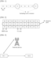
- a network device configures a downlink (downlink, DL) slot and a UL slot.
- D represents a DL slot
- U represents a UL slot.
- SL communication is performed in a licensed spectrum, only a resource in a UL slot can be configured for an SL resource pool. Therefore, not every slot has an SL communication resource.
- an SL resource pool includes L consecutive or non-consecutive slots, and there are N consecutive subchannels in each slot. In other words, bandwidth sizes of all slots are the same.
- an SBFD mode is being discussed in 5G NR.
- the downlink subband is used by a network device to send information to UE, and the uplink subband is used by the UE to send information to the network device.
- the network device may simultaneously perform downlink sending and uplink receiving in the SBFD slot.
- the SBFD mode can reduce an uplink transmission latency. As shown in FIG.
- a first-type time domain unit included in a first resource pool may correspond to N1 first-type frequency domain units
- a second-type time domain unit may correspond to N2 second-type frequency domain units.
- Values of N1 and N2 are not limited.
- N1 and N2 may be different.
- the first resource pool may include different quantities of frequency domain units in different types of time domain units.
- the first resource pool may include all available frequency domain resources in a UL slot, and may also include all available frequency domain resources in an SBFD slot. This reduces a waste of resources and improves resource utilization.
- SL may be referred to as "sidelink”.
- SL information may be referred to as sidelink information
- SL data may be referred to as sidelink data.
- SL may also be briefly referred to as "side”.
- the SL information may be referred to as side information
- the SL data may be referred to as side data. This is used as an example below.
- the frequency domain unit is, for example, a subband or a subchannel (subchannel).
- the frequency domain unit in embodiments of this application is a minimum frequency domain resource scheduling unit in an SL resource pool (for example, the first resource pool to be described below). For example, during resource scheduling, scheduling is performed by using a frequency domain unit as a unit.
- the time domain unit is, for example, a subframe (subframe), a slot, a mini-slot (mini-slot), or an orthogonal frequency division multiplexing (orthogonal frequency division multiplexing, OFDM) symbol (symbol).
- subframe subframe
- slot slot
- mini-slot mini-slot
- OFDM orthogonal frequency division multiplexing
- the first time domain unit is the first-type time domain unit
- the second UE determines, based on the FRIV included in the SCI sent in the first time domain unit, that the reserved resource occupies a subchannel 2 in a time domain unit in a resource reservation period.
- the SCI further indicates that the reserved resource occupies the subchannel set 3 in the second time domain unit.
- the first UE may send the side control information, where the side control information may schedule at least one TB corresponding to the first data. Therefore, optionally, the method may further include S404: The first UE sends the at least one TB corresponding to the first data in a first frequency domain unit in a third time domain unit.
- the second UE receives the at least one TB corresponding to the first data in the first frequency domain unit in the third time domain unit.
- the third time domain unit and the first time domain unit may be a same time domain unit, or may be different time domain units.
- the second UE may receive the side control information, and the receiving end of the first data may be the second UE, or may be another UE. In this embodiment of this application, the second UE is used as an example.
- the second UE may send feedback information by using a physical sidelink feedback channel (physical sidelink feedback channel, PSFCH).
- the feedback information is, for example, hybrid automatic repeat request (hybrid automatic repeat request, HARQ) feedback, for example, a positive acknowledgment (ACK) or a negative acknowledgment (NACK), to indicate that the at least one TB corresponding to the first data is successfully received or fails to be received.
- the PSFCH resource is a periodic resource configured (pre-configured) for the first resource pool, and may be configured by using the configuration information. For example, the configuration information may be used to configure a period of the PSFCH resource by using a third parameter.
- the third parameter is, for example, a periodic PSFCH resource (periodPSFCHresource) parameter.
- AGC automatic gain control
- the last symbol in the slot is a guard period (guard period, GP) symbol, and is mainly used for receiving-sending conversion or sending-receiving conversion.
- GP guard period
- For a slot including a PSFCH resource in addition to the first OFDM symbol being an AGC symbol and the last OFDM symbol being a GP symbol, there are system-level resource overheads of three additional OFDM symbols.
- One of the three OFDM symbols is a GP symbol, one OFDM symbol is an AGC symbol, and the other OFDM symbol is a PSFCH symbol.
- a minimum time gap between a resource used to receive data and a resource used to send feedback information may be configured (pre-configured) for the first resource pool.
- the time gap is configured by using a fourth parameter, and the fourth parameter may be included in the configuration information.
- the fourth parameter is a minimum time gap PSFCH (MinTimeGapPSFCH) parameter, and a value of the MinTimeGapPSFCH parameter may be 2 or 3, or may be another value.
- MinTimeGapPSFCH 3
- Both the sending UE for example, the first UE
- the receiving UE for example, the second UE
- a PSSCH resource in every four time domain units is associated with a PSFCH resource in one time domain unit, and each of the four time domain units is at least two slots apart from a slot in which the associated PSFCH resource is located.
- the second PSFCH resource (a PSFCH resource in a slot 7) is associated with a PSSCH resource of four time domain units (a slot 2 to a slot 5) in the first dashed line box
- the third PSFCH resource (a PSFCH resource in a slot 11) is associated with a PSSCH resource of four time domain units (a slot 6 to a slot 9) in the second dashed line box.
- the first resource pool may include the first-type time domain unit and the second-type time domain unit.
- Different types of time domain units correspond to different quantities of frequency domain units.
- some PSFCH resources may be associated with the second-type time domain unit (for example, slots associated with a slot 7 in FIG. 5 include a slot 2 to a slot 5, the slot 5 is a second-type time domain unit, and a PSFCH resource in the slot 7 is associated with the second-type time domain unit).
- some PSFCH resources are not associated with the second-type time domain unit (for example, slots associated with a slot 11 in FIG.
- FIG. 5 are a slot 6 to a slot 9, and are first-type time domain units, and a PSFCH resource in the slot 11 is not associated with the second-type time domain unit). Because the second-type time domain unit included in the first resource pool corresponds to a large quantity of frequency domain units, a PSFCH resource associated with the second-type time domain unit is associated with more frequency domain units, and a PSFCH resource that is not associated with the second-type time domain unit is associated fewer frequency domain units.
- FIG. 5 is used as an example.
- the PSFCH resource in the slot 7 may be associated with a total of 18 frequency domain units in the slot 2 to the slot 5
- the PSFCH resource in the slot 11 may be associated with a total of 12 frequency domain units in the slot 6 to the slot 9.
- a PSFCH resource in a time domain unit may be divided into a plurality of feedback resource unit sets in frequency domain.
- a quantity of feedback resource unit sets obtained through division may be equal to a quantity of frequency domain units associated with the PSFCH resource.
- the frequency domain units associated with the PSFCH resource may be in one-to-one correspondence with the feedback resource unit sets.
- the first resource pool includes a sixth time domain unit
- the sixth time domain unit includes a PSFCH resource
- the PSFCH resource in the sixth time domain unit is associated with L2 time domain units
- the L2 time domain units include the second-type time domain unit.
- the PSFCH resource may be divided into H2 feedback resource unit sets in frequency domain, and the H2 feedback resource unit sets are in one-to-one correspondence with frequency domain units in the L2 time domain units. Both L2 and H2 are positive integers.
- APFSCH resource in a time domain unit is divided into a plurality of feedback resource unit sets in frequency domain.
- Each feedback resource unit set may include one or more feedback resource units.
- the feedback resource unit is, for example, a resource unit including e time domain subunits and f frequency domain subunits, and both e and f are positive integers.
- the time domain subunit is, for example, an OFDM symbol, and a bandwidth of the frequency domain subunit is, for example, the same as a bandwidth of a PRB.
- the feedback resource unit is a PRB, and in this case, the feedback resource unit set may also be understood as a PRB set; or e may be 2 or another value.
- a time domain unit associated with the PSFCH resource in the slot 11 does not include the second-type time domain unit, and a slot 15 is the second-type time domain unit. Therefore, e corresponding to PSFCH resources in the slot 11 and the slot 15 may be 1.
- the PSFCH resource is associated with a large quantity of frequency domain units. In other words, the PSFCH resource is used to transmit more feedback information. Setting e to be greater than 1 is equivalent to making the feedback resource unit include more resources in time domain, to transmit more feedback information. If the time domain unit in which the PSFCH resource is located is the second-type time domain unit, frequency domain resources of the PSFCH resource are abundant, and can be used to transmit more feedback information.
- a time domain resource of the feedback resource unit may not need to be extended.
- the first UE sends the at least one TB corresponding to the first data in the first frequency domain unit in the third time domain unit, a PSFCH resource associated with the third time domain unit is located in a fourth time domain unit, and the fourth time domain unit is associated with L1 time domain units in total. If the L1 time domain units include the second-type time domain unit, and the fourth time domain unit is the first-type time domain unit, e may be greater than 1.
- the method may further include S405: The second UE determines the feedback resource unit used to send the feedback information.
- the first UE may also determine a feedback resource unit used to receive the feedback information. A manner of determining the feedback resource unit by the first UE is similar to that of determining the feedback resource unit by the second UE.
- the first UE sends, in the first frequency domain unit in the third time domain unit, the at least one TB corresponding to the first data.
- the PSFCH resource associated with the third time domain unit is located in the fourth time domain unit
- the fourth time domain unit is associated with L1 time domain units in total
- the third time domain unit belongs to the L1 time domain units.
- the first UE or the second UE may determine, from the first feedback resource unit set, a feedback resource unit used to transmit the feedback information of the at least one TB corresponding to the first data.
- the determined feedback resource unit is a first feedback resource unit.
- manners of determining the first feedback resource unit from the first feedback resource unit set may also be different. The following describes the manners by using examples.
- the first feedback resource unit set includes D feedback resource units. Further, the first UE or the second UE may determine, based on the configuration information, that a quantity of cyclic shift pairs (cyclic shift pair) that can be used in a feedback information sequence is G. D ⁇ G feedback resources may be determined in total. The feedback resources include both a time-frequency resource (that is, the D feedback resource units) and a code domain resource (that is, the G cyclic shift pairs). The first UE or the second UE may further determine a corresponding feedback resource from the D ⁇ G feedback resources based on a value of ( P ID + M ID ) mod (D ⁇ G), and a time-frequency resource included in the feedback resource is the first feedback resource unit.
- P ID is determined based on a source ID corresponding to the PSSCH used to transmit the first data
- M ID is set to 0 or is determined based on a group ID configured by a higher layer.
- P ID is set to 0 or is determined based on the source ID corresponding to the PSSCH used to transmit the first data
- M ID is determined based on a destination ID corresponding to the PSSCH used to transmit the first data or is determined based on a group ID configured by a higher layer.
- One feedback resource may be used to transmit an ACK, or may be used to transmit a NACK. Specific transmitted information may be determined based on a result of decoding the received first data by the second UE.
- the first UE or the second UE may determine one or more of the following based on an identifier related to the first data: an index of the first feedback resource unit, an index of a frequency domain subunit corresponding to the first feedback resource unit, a cyclic shift of a sequence corresponding to the first feedback resource unit, or an orthogonal cover code (orthogonal cover code, OCC) corresponding to the first feedback resource unit. If one or more of the foregoing are determined, the first feedback resource unit is determined.
- the OCC is, for example, a Walsh (Walsh) code sequence or a discrete Fourier transform (discrete Fourier transform, DFT) sequence.
- the sequence corresponding to the first feedback resource unit may be understood as:
- the sequence may be used as feedback information carried in the first feedback resource unit, and the sequence is, for example, a ZC (Zadoff Chu) sequence, or may be another sequence.
- ZC Zero Cicle Chemetic Coding
- a total quantity of resource indexes of feedback resource units included in a PSFCH resource using two frequency domain subunits is twice a total quantity of resource indexes of feedback resource units included in a PSFCH resource using one frequency domain subunit. Therefore, a capacity of the PSFCH resource is expanded, and more feedback information can be carried.
- the identifier related to the first data includes, for example, one or more of the following: an identifier of a service corresponding to the first data, an identifier of a transmitting end (for example, the first UE) of the first data, an identifier of a receiving end (for example, the second UE) of the first data, or a multicast-related identifier.
- the service corresponding to the first data is a multicast service, and the first data is sent in a multicast manner
- the multicast-related identifier may include an identifier of a group header device and/or an identifier of a group member device in the multicast group.
- the method may further include S406:
- the second UE sends the feedback information of the at least one TB corresponding to the first data in the first feedback resource unit in the fourth time domain unit.
- the first UE receives the feedback information in the first feedback resource unit in the fourth time domain unit.
- the first UE and the second UE may determine the first feedback resource unit in a same manner (as described above). Therefore, the first UE can correctly receive the feedback information.
- the first-type time domain unit included in the first resource pool may correspond to the N1 first-type frequency domain units
- the second-type time domain unit may correspond to the N2 second-type frequency domain units.
- Values of N1 and N2 are not limited.
- N1 and N2 may be different.
- the first resource pool may include different quantities of frequency domain units in different types of time domain units.
- the first resource pool may include all available frequency domain resources in a UL slot, and may also include all available frequency domain resources in an SBFD slot. This reduces a waste of resources and improves resource utilization.
- the side control information indicates the frequency domain resource occupied by the reserved resource. Regardless of a type of time domain resource occupied by the reserved resource, the side control information can indicate the frequency domain unit occupied by the reserved resource, so that the receiving UE can correctly receive data, and another UE can perform interference avoidance based on the side control information when selecting a resource.
- a capacity of the PFSCH resource used to send the feedback information may be further extended, to transmit more feedback information, to meet requirements of more users.
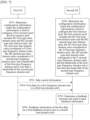
- FIG. 7 is a flowchart of the method.
- First UE determines configuration information.
- the configuration information may be used to configure a first resource pool, and the first resource pool may be used for communication between the first UE and another UE, for example, used for information transmission between the first UE and the another UE.
- the first resource pool may include M1 first-type time domain units and M2 second-type time domain units. Both M1 and M2 are positive integers, and a value relationship between M1 and M2 is not limited. Duration of the first-type time domain unit may be equal to duration of the second-type time domain unit. For example, both the first-type time domain unit and the second-type time domain unit are slots or subframes. In this embodiment of this application, the time domain units may be classified based on frequency domain units corresponding to the time domain units. For example, the first-type time domain unit may correspond to N first-type frequency domain units in the first resource pool, the second-type time domain unit may correspond to N second-type frequency domain units in the first resource pool, and N is a positive integer.
- a time domain unit in the first resource pool if a time domain unit corresponds to N first-type frequency domain units in the first resource pool, the time domain unit is a first-type time domain unit. If a time domain unit corresponds to N second-type frequency domain units in the first resource pool, the time domain unit is a second-type time domain unit. That a time domain unit corresponds to (or is associated with) a frequency domain unit may be understood as: a resource in which the frequency domain unit is located is in the time domain unit, or a time domain location of a resource in which the frequency domain unit is located is a time domain location of the time domain unit.
- a bandwidth of the first-type frequency domain unit may be less than a bandwidth of the second-type frequency domain unit.
- a quantity of resource units included in the first-type frequency domain unit may be less than a quantity of resource units included in the second-type frequency domain unit.
- the resource unit is, for example, a PRB.
- the bandwidth of the second-type frequency domain unit may be a multiple of the bandwidth of the first-type frequency domain unit, or the two may not be in a multiple relationship.
- the first resource pool may include frequency domain units of different bandwidths in different time domain units, so that the resource pool is configured more flexibly.
- the first-type time domain unit is an SBFD slot
- the second-type time domain unit is a UL slot. According to the technical solution in this embodiment of this application, frequency domain resources in the two types of slots may be included in the first resource pool, to reduce a waste of resources and improve resource utilization.
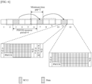
- FIG. 8 is an example of the first resource pool.
- an example in which a time domain unit is a slot is used. Slots included in FIG. 8 may be all or a part of slots in the first resource pool. This is not limited herein.
- FIG. 8 uses an example in which both the first-type frequency domain unit and the second-type frequency domain unit are subchannels. For example, a first-type slot corresponds to a subchannel 1 to a subchannel 3, and a second-type slot also corresponds to a subchannel 1 to a subchannel 3.
- a bandwidth of a subchannel corresponding to the first-type slot is less than a bandwidth of a subchannel corresponding to the second-type slot.
- "D" in FIG. 8 indicates that the frequency domain resources are resources used for downlink transmission and do not belong to the first resource pool.
- the bandwidth of the second-type frequency domain unit is three times the bandwidth of the first-type frequency domain unit, and frequency domain locations of the second-type frequency domain unit and the first-type frequency domain unit are aligned. This is not limited in practice.
- the first UE determines the configuration information, or a device that configures the configuration information, refer to the descriptions of the embodiment shown in FIG. 4 .
- the configuration information may include one or more of the following: information about an index set of the M1 first-type time domain units or indexes of the M1 first-type time domain units; information about an index set of the M2 second-type time domain units or indexes of the M2 second-type time domain units; frequency domain location information of the N first-type frequency domain units; frequency domain location information of N second-type frequency domain units; a value of N; a quantity of PRBs (a quantity of RBs, a quantity of REs, a quantity of subcarriers, or the like) included in the first-type frequency domain unit; or a quantity of PRBs (a quantity of RBs, a quantity of REs, a quantity of subcarriers, or the like) included in the second-type frequency domain unit.
- parameters such as the information about the index set of the M1 first-type time domain units, the indexes of the M1 first-type time domain units, the information about the index set of the M2 second-type time domain units, the indexes of the M2 second-type time domain units, the frequency domain location information of the N first-type frequency domain units, and the frequency domain location information of the N second-type frequency domain units, refer to the embodiment shown in FIG. 4 .
- the quantity of resource units included in the first-type frequency domain unit may be different from the quantity of resource units included in the second-type frequency domain unit.
- the quantity of resource units included in the first-type frequency domain unit may be less than the quantity of resource units included in the second-type frequency domain unit. Therefore, the configuration information may be used to configure the quantity of resource units included in the first-type frequency domain unit and/or configure the quantity of resource units included in the second-type frequency domain unit.
- S702 Second UE determines the configuration information.
- the configuration information is consistent with the configuration information described in S701. For more content of S702, for example, information included in the configuration information and a manner in which the second UE determines the configuration information, refer to the descriptions of S701.
- the method may further include S703:
- the first UE sends side control information.
- the second UE receives the side control information.
- the first UE may send the side control information by using a resource (for example, a first time domain unit) in the first resource pool.
- the side control information is, for example, SCI. For a description of this, refer to the embodiment shown in FIG. 4 .
- the side control information may be used to schedule a TB corresponding to data.
- the data is referred to as first data
- the first data may correspond to one or more TBs
- the side control information may schedule a part or all of the one or more TBs, for example, may schedule at least one of the one or more TBs.
- the side control information may further indicate a reserved resource of the first data, and the reserved resource is a transmission resource reserved for the first data.
- UE that receives the side control information may perform interference avoidance based on the reserved resource.
- the side control information may indicate a time domain location and/or a frequency domain location of a PSCCH used to carry the side control information, and indicate a time domain location and/or a frequency domain location of a PSSCH associated with the PSCCH.
- the PSSCH may carry at least one TB corresponding to the first data.
- the side control information may further indicate a frequency domain unit occupied by the reserved resource in K time domain units, and K is a positive integer.
- the K time domain units are all time domain units included in the reserved resource in a resource reservation period, or are reserved time domain units included in a resource reservation period. Therefore, the side control information is equivalent to indicating a time domain unit and/or a frequency domain unit occupied by the reserved resource in a resource reservation period.
- the time domain unit may be referred to as a reserved time domain unit. All or a part of time domain units included in the resource reservation period may be used as reserved time domain units.
- the side control information may further indicate a resource reservation period, for example, indicate a quantity of resource reservation periods (which may be understood as a quantity of periodicities in which resources are reserved for the first data), and/or duration of a resource reservation period (for example, the duration is longer than or equal to total duration of the K time domain units).
- a receiving end (for example, the second UE) of the side control information can determine the reserved resource based on the side control information.
- the reserved resource includes resources reserved for the first data in all resource reservation periods reserved for the first data. For example, if the side control information indicates that the quantity of resource reservation periods is 3, and duration of a resource reservation period is 1 slot, it is equivalent that resources in three slots are reserved for the first data.
- the side control information indicates the frequency domain unit occupied by the reserved resource in the K time domain units.
- the side control information includes an FRIV
- the FRIV may indicate the frequency domain unit occupied by the reserved resource in the K time domain units, without using other indication information.
- a calculation manner of a value of the FRIV, and the like refer to the embodiment shown in FIG. 4 .
- a quantity of bits occupied by the FRIV may be determined based on a first parameter N subchannel SL .
- a value of the first parameter may be N, indicating a quantity of frequency domain units included in each time domain unit in the first resource pool.
- the FRIV may indicate the frequency domain unit reserved for the first data in the resource reservation period.
- the receiving end (for example, the second UE) of the side control information may determine a value of the first parameter based on N, to determine the quantity of bits of the FRIV.
- the side control information may include a parameter used to decode the at least one TB corresponding to the first data.
- the parameter includes a modulation and coding scheme (modulation and coding scheme, MCS).
- MCS modulation and coding scheme
- the side control information indicates a first MCS and a second MCS, the first MCS is applicable to the first-type time domain unit in the K time domain units, and the second MCS is applicable to the second-type time domain unit in the K time domain units.
- the first MCS and the second MCS may be different.
- spectral efficiency corresponding to the first MCS may be higher than spectral efficiency corresponding to the second MCS, and the spectral efficiency may be a product of a modulation order and a channel coding code rate. If spectral efficiency of an MCS is high, it indicates that the MCS is a higher-order MCS. In other words, it may be considered that the first MCS is a higher-order MCS relative to the second MCS, and the second MCS is a lower-order MCS. In other words, because the bandwidth of the second-type frequency domain unit is large, a lower-order MCS may be used in the second-type frequency domain unit, to improve data transmission reliability.
- a quantity of frequency domain units occupied by the reserved resource in the first-type time domain unit may be equal to a quantity of frequency domain units occupied by the reserved resource in the second-type time domain unit.
- the quantity of frequency domain units occupied by the reserved resource in the first-type time domain unit may not be equal to the quantity of frequency domain units occupied by the reserved resource in the second-type time domain unit, so that data transmission is more flexible.
- another optional implementation is provided, that is, a second indication manner of the side control information. In this indication manner, the quantity of frequency domain units occupied by the reserved resource in the first-type time domain unit may not be equal to the quantity of frequency domain units occupied by the reserved resource in the second-type time domain unit.
- the frequency domain unit occupied by the reserved resource in the K time domain units is indicated with reference to second indication information.
- side control information sent in a type of time domain unit may include the second indication information.
- the second indication information may indicate a quantity of frequency domain units occupied by the reserved resource in the other type of time domain unit (the second-type time domain unit or the first-type time domain unit).
- the first UE sends the side control information by using the first time domain unit in the first resource pool.
- the K time domain units include a second time domain unit
- the second time domain unit is the second-type time domain unit
- the second indication information included in the side control information may indicate a quantity of frequency domain units occupied by the reserved resource in the second time domain unit.
- the first UE sends the side control information by using the first time domain unit in the first resource pool.
- the K time domain units include a third time domain unit
- the third time domain unit is the first-type time domain unit
- the second indication information included in the side control information may indicate a quantity of frequency domain units occupied by the reserved resource in the third time domain unit.
- the first UE sends SCI in a first-type slot
- the SCI indicates that a second-type slot occupied by the reserved resource is a slot 5 in FIG. 8
- an FRIV included in the SCI indicates that the reserved resource occupies a subchannel 2 and a subchannel 3 in the slot 5.
- the SCI further includes second indication information, and the second indication information indicates that a quantity of subchannels occupied by the reserved resource in the second-type slot is 1.
- the first UE may determine that the reserved resource occupies the subchannel 2 or the subchannel 3 in the slot 5. There may be a corresponding manner to determine whether the reserved resource occupies the subchannel 2 or the subchannel 3 in the slot 5.
- a quantity of frequency domain units occupied by the reserved resource in a time domain unit of a type different from that of a time domain unit in which the SCI is located is less than a quantity of frequency domain units occupied by the reserved resource in a time domain unit of a type the same as that of the time domain unit in which the SCI is located.
- a frequency domain unit with a smallest sequence number indicated by the FRIV may be used as a frequency domain unit occupied by the reserved resource in the time domain unit of a type different from that of the time domain unit in which the SCI is located.
- FIG. 8 is still used as an example.
- the quantity of frequency domain units occupied by the reserved resource in the time domain unit (the second-type slot) of the type different from that of the time domain unit in which the SCI is located is 1, and is less than a quantity 2 of frequency domain units occupied by the reserved resource in a time domain unit (the first-type slot) of the type the same as that of the time domain unit in which the SCI is located, and a subchannel with a smallest sequence number indicated by the FRIV is a subchannel 2.
- the first UE may determine that the reserved resource occupies the subchannel 2 in the second-type slot (for example, the slot 5).
- a quantity of frequency domain units occupied by the reserved resource in a time domain unit of a type different from that of a time domain unit in which the SCI is located is less than a quantity of frequency domain units occupied by the reserved resource in a time domain unit of a type the same as that of the time domain unit in which the SCI is located.
- a frequency domain unit with a largest sequence number indicated by the FRIV may be used as a frequency domain unit occupied by the reserved resource in the time domain unit of a type different from that of the time domain unit in which the SCI is located.
- FIG. 8 is still used as an example.
- the quantity of frequency domain units occupied by the reserved resource in the time domain unit (the second-type slot) of the type different from that of the time domain unit in which the SCI is located is 1, and is less than a quantity 2 of frequency domain units occupied by the reserved resource in the time domain unit (the first-type slot) of the type the same as that of the time domain unit in which the SCI is located, and a subchannel with a largest sequence number indicated by the FRIV is a subchannel 3.
- the first UE may determine that the reserved resource occupies the subchannel 3 in the second-type slot (for example, the slot 5).
- the first UE sends SCI in a second-type slot
- the SCI indicates that a first-type slot occupied by the reserved resource is a slot 6 in FIG. 8
- an FRIV included in the SCI indicates that the reserved resource occupies a subchannel 2 in the slot 6.
- the SCI further includes second indication information, and the second indication information indicates that a quantity of subchannels occupied by the reserved resource in the first-type slot is 2.
- the first UE may determine that the reserved resource occupies the subchannel 2 and a subchannel 3 in the slot 6, or occupies a subchannel 1 and the subchannel 2 in the slot 6. There may be a corresponding manner of determining subchannels that are occupied by the reserved resource in the slot 6.
- a quantity of frequency domain units occupied by the reserved resource in a time domain unit of a type different from that of a time domain unit in which the SCI is located is greater than a quantity of frequency domain units occupied by the reserved resource in a time domain unit of a type the same as that of the time domain unit in which the SCI is located.
- a frequency domain unit with a smallest sequence number indicated by the FRIV may be used as a start frequency domain unit occupied by the reserved resource in the time domain unit of a type different from that of the time domain unit in which the SCI is located.
- an index of the frequency domain unit with the smallest sequence number indicated by the FRIV is j, where 0 ⁇ j ⁇ N.
- the quantity of frequency domain units occupied by the reserved resource in the time domain unit of the type different from that of the time domain unit in which the SCI is located is Q, where 0 ⁇ Q ⁇ N. If j+Q ⁇ N, indexes of frequency domain units occupied by the reserved resource in the time domain unit of the type different from that of the time domain unit in which the SCI is located are j to j+Q-1. If j+Q>N, indexes of frequency domain units occupied by the reserved resource in the time domain unit of the type different from that of the time domain unit in which the SCI is located are N-Q to N-1, or j to N-1 and 0 to Q-(N-j)-1.
- FIG. 8 is still used as an example.
- the quantity of frequency domain units occupied by the reserved resource in the time domain unit (the first-type slot) of the type different from that of the time domain unit in which the SCI is located is 2, and is greater than a quantity 1 of frequency domain units occupied by the reserved resource in the time domain unit (the first-type slot) of the type the same as that of the time domain unit in which the SCI is located, and a subchannel indicated by the FRIV is a subchannel 2.
- the first UE may determine that the reserved resource occupies the subchannel 2 and the subchannel 3 in the first-type slot (for example, the slot 6).
- a quantity of frequency domain units occupied by the reserved resource in a time domain unit of a type different from that of a time domain unit in which the SCI is located is greater than a quantity of frequency domain units occupied by the reserved resource in a time domain unit of a type the same as that of the time domain unit in which the SCI is located.
- a frequency domain unit with a smallest sequence number indicated by the FRIV may be used as an end frequency domain unit occupied by the reserved resource in the time domain unit of a type different from that of the time domain unit in which the SCI is located.
- an index of the frequency domain unit with the smallest sequence number indicated by the FRIV is j, where 0 ⁇ j ⁇ N.
- the quantity of frequency domain units occupied by the reserved resource in the time domain unit of the type different from that of the time domain unit in which the SCI is located is Q, where 0 ⁇ Q ⁇ N. If j-Q+1 ⁇ 0, indexes of frequency domain units occupied by the reserved resource in the time domain unit of the type different from that of the time domain unit in which the SCI is located are j-Q+1 to j. If j-Q+1 ⁇ 0, indexes of frequency domain units occupied by the reserved resource in the time domain unit of the type different from that of the time domain unit in which the SCI is located are 0 to Q-1, or 0 to j and N-(Q-(j+1)) to N-1.
- FIG. 8 is still used as an example.
- the quantity of frequency domain units occupied by the reserved resource in the time domain unit (the first-type slot) of the type different from that of the time domain unit in which the SCI is located is 2, and is greater than a quantity 1 of frequency domain units occupied by the reserved resource in the time domain unit (the first-type slot) of the type the same as that of the time domain unit in which the SCI is located, and a subchannel indicated by the FRIV is a subchannel 2.
- the first UE may determine that the reserved resource occupies the subchannel 1 and the subchannel 2 in the first-type slot (for example, the slot 6).
- the first UE may send the side control information, where the side control information may schedule the one or more TBs corresponding to the first data. Therefore, optionally, the method may further include S704: The first UE sends the at least one TB corresponding to the first data in a first frequency domain unit in a third time domain unit.
- the second UE receives the at least one TB corresponding to the first data in the first frequency domain unit in the third time domain unit.
- the third time domain unit and the first time domain unit may be a same time domain unit, or may be different time domain units.
- the second UE may receive the side control information, and the receiving end of the first data may be the second UE, or may be another UE. In this embodiment of this application, the second UE is used as an example.
- the first resource pool includes the first-type time domain unit and the second-type time domain unit
- quantities of frequency domain units corresponding to different types of time domain units are the same. Therefore, both a PSFCH resource that is associated with the second-type time domain unit and a PSFCH resource that is not associated with the second-type time domain unit are associated with a same quantity of frequency domain units.
- FIG. 8 is used as an example.
- a PSFCH resource in a slot 7 is a PSFCH resource associated with the second-type time domain unit (the slot 7 is associated with a slot 2 to a slot 5, and the slot 5 is the second-type time domain unit).
- the PSFCH resource in the slot 7 may be associated with 12 frequency domain units.
- the first resource pool includes a fourth time domain unit
- the fourth time domain unit includes a PSFCH resource
- the fourth time domain unit is associated with L1 time domain units
- the L1 time domain units include the second-type time domain unit, or do not include the second-type time domain unit.
- the PSFCH resource may be divided into H1 feedback resource unit sets in frequency domain, and the H1 feedback resource unit sets are in one-to-one correspondence with frequency domain units in the L1 time domain units. Both L1 and H1 are positive integers.
- FIG. 8 is used as an example.
- the method may further include S705: The second UE determines the feedback resource unit used to send the feedback information.
- the first UE may also determine a feedback resource unit used to receive the feedback information. A manner of determining the feedback resource unit by the first UE is similar to that of determining the feedback resource unit by the second UE.
- the first UE sends, in the first frequency domain unit in the third time domain unit, the at least one TB corresponding to the first data.
- a PSFCH resource associated with the third time domain unit is located in the fourth time domain unit, the fourth time domain unit is associated with L1 time domain units in total, and the third time domain unit belongs to the L1 time domain units.
- the first UE or the second UE may determine, from the first feedback resource unit set, a feedback resource unit used to transmit the feedback information of the at least one TB corresponding to the first data.
- the determined feedback resource unit is a first feedback resource unit.
- a quantity of frequency domain units corresponding to the first-type time domain unit is equal to a quantity of frequency domain units corresponding to the second-type time domain unit. Therefore, there is no need to make excessive changes to side control information, a feedback mechanism, and the like, and this can be better compatible with the conventional technology.
- the communication apparatus 900 includes at least one processor 901.
- the processor 901 may be configured to perform internal processing of the apparatus, to implement a specific control processing function.
- the processor 901 includes instructions.
- the processor 901 may store data.
- different processors may be independent components, may be located at different physical locations, or may be located on different integrated circuits.
- different processors may be integrated into one or more processors, for example, integrated into one or more integrated circuits.
- the communication apparatus 900 includes one or more memories 903, configured to store instructions.
- the memory 903 may further store data.
- the processor and the memory may be separately disposed, or may be integrated together.
- the communication apparatus 900 includes a communication line 902 and at least one communication interface 904. Because the memory 903, the communication line 902, and the communication interface 904 are all optional, the memory 903, the communication line 902, and the communication interface 904 are all represented by dashed lines in FIG. 9 .
- the processor 901 may include a general-purpose central processing unit (central processing unit, CPU), a microprocessor, an application-specific integrated circuit (application-specific integrated circuit, ASIC), or one or more integrated circuits configured to control program execution of the solutions in this application.
- CPU central processing unit
- ASIC application-specific integrated circuit
- the communication line 902 may include a path for transmitting information between the foregoing components.
- the memory 903 may be an electrically erasable programmable read-only memory (electrically erasable programmable read-only memory, EEPROM), a compact disc read-only memory (compact disc read-only memory, CD-ROM) or another compact disc storage, an optical disc storage (including a compact optical disc, a laser disc, an optical disc, a digital versatile disc, a Blu-ray disc, or the like), a magnetic disk storage medium or another magnetic storage device, or any other medium that can be used to carry or store expected program code in an instruction or data structure form and that can be accessed by a computer.
- the memory 903 may exist independently, and is connected to the processor 901 through the communication line 902. Alternatively, the memory 903 may be integrated with the processor 901.
- the memory 903 is configured to store computer-executable instructions for performing the solutions in this application, and the processor 901 controls execution.
- the processor 901 is configured to execute the computer-executable instruction stored in the memory 903, to implement the communication method provided in the foregoing embodiments of this application.
- the computer-executable instructions in this embodiment of this application may also be referred to as application program code. This is not specifically limited in this embodiment of this application.
- the processor 901 may include one or more CPUs, for example, a CPU 0 and a CPU 1 in FIG. 9 .
- the communication apparatus 900 may include a plurality of processors, for example, the processor 901 and a processor 905 in FIG. 9 .
- Each of the processors may be a single-core (single-CPU) processor, or may be a multi-core (multi-CPU) processor.
- the processor herein may be one or more devices, circuits, and/or processing cores configured to process data (for example, computer program instructions).
- the chip includes the processor 901 (and may further include a processor 905), the communication line 902, and the communication interface 904, and optionally, may further include the memory 903.
- the communication interface 904 may be an input interface, a pin, or a circuit.
- the memory 903 may be a register, a cache, or the like.
- the processor 901 and the processor 905 each may be a general-purpose CPU, a microprocessor, an ASIC, or one or more integrated circuits configured to control program execution of the method in any one of the foregoing embodiments.
- the apparatus may be divided into functional modules based on the foregoing method examples.
- each functional module may be obtained through division based on each corresponding function, or two or more functions may be integrated into one processing module.
- the integrated module may be implemented in a form of hardware, or may be implemented in a form of a software functional module.
- module division is an example, and is merely a logical function division. In actual implementation, another division manner may be used.
- FIG. 10 is a diagram of an apparatus.
- the apparatus 1000 may be the first UE or the second UE in the foregoing method embodiments, or a chip in the first UE or a chip in the second UE.
- the apparatus 1000 includes a sending unit 1001, a processing unit 1002, and a receiving unit 1003.
- the apparatus 1000 may be configured to implement the steps performed by the first UE or the second UE in the method in embodiments of this application.
- the apparatus 1000 may be configured to implement the steps performed by the first UE or the second UE in the method in embodiments of this application.
- functions/implementation processes of the sending unit 1001, the receiving unit 1003, and the processing unit 1002 in FIG. 10 may be implemented by the processor 901 in FIG. 9 by invoking the computer-executable instructions stored in the memory 903.
- a function/an implementation process of the processing unit 1002 in FIG. 10 may be implemented by the processor 901 in FIG. 9 by invoking the computer-executable instructions stored in the memory 903, and functions/implementation processes of the sending unit 1001 and the receiving unit 1003 in FIG. 10 may be implemented by the communication interface 904 in FIG. 9 .
- functions/implementation processes of the sending unit 1001 and the receiving unit 1003 may alternatively be implemented by using a pin, a circuit, or the like.
- This application further provides a computer-readable storage medium.
- the computer-readable storage medium stores a computer program or instructions.
- the method performed by the first UE or the second UE in the foregoing method embodiments is implemented.
- the functions in the foregoing embodiments may be implemented in a form of a software functional unit and sold or used as an independent product.
- the technical solutions of this application essentially, or the part contributing to conventional technologies, or a part of the technical solutions may be implemented in a form of a software product.
- the computer software product is stored in a storage medium, and includes several instructions for instructing a computer device (which may be a personal computer, a server, a network device, or the like) to perform all or a part of the steps of the methods described in embodiments of this application.
- the storage medium includes any medium that can store program code, such as a USB flash drive, a removable hard disk drive, a ROM, a RAM, a magnetic disk, or an optical disc.
- the computer program product includes computer program code.
- the computer program code When the computer program code is run on a computer, the computer is enabled to perform the method performed by the first UE or the second UE in any one of the foregoing method embodiments.
- An embodiment of this application further provides a processing apparatus, including a processor and an interface.
- the processor is configured to perform the method performed by the first UE or the second UE in any one of the foregoing method embodiments.
- All or a part of the foregoing embodiments may be implemented by using software, hardware, firmware, or any combination thereof.
- software is used to implement the embodiments, all or a part of the embodiments may be implemented in a form of a computer program product.
- the computer program product includes one or more computer instructions. When the computer program instructions are loaded and executed on the computer, the procedure or functions according to embodiments of this application are all or partially generated.
- the computer may be a general-purpose computer, a dedicated computer, a computer network, or other programmable apparatuses.
- the computer instructions may be stored in a computer-readable storage medium or may be transmitted from a computer-readable storage medium to another computer-readable storage medium.
- the computer instructions may be transmitted from a website, computer, server, or data center to another website, computer, server, or data center in a wired (for example, a coaxial cable, an optical fiber, or a digital subscriber line (DSL)) or wireless (for example, infrared, radio, or microwave) manner.
- the computer-readable storage medium may be any usable medium accessible by the computer, or a data storage device, for example, a server or a data center, integrating one or more usable media.
- the usable medium may be a magnetic medium (for example, a floppy disk, a hard disk drive, or a magnetic tape), an optical medium (for example, a DVD), a semiconductor medium (for example, a solid-state drive, (solid-state disk, SSD)), or the like.
- a magnetic medium for example, a floppy disk, a hard disk drive, or a magnetic tape
- an optical medium for example, a DVD
- a semiconductor medium for example, a solid-state drive, (solid-state disk, SSD)
- Various illustrative logic units and circuits described in embodiments of this application may implement or operate the described functions by a general-purpose processor, a digital signal processor (digital signal processor, DSP), an application-specific integrated circuit (application-specific integrated circuit, ASIC), a field-programmable gate array (field-programmable gate array, FPGA) or another programmable logic apparatus, a discrete gate or transistor logic, a discrete hardware component, or a design of any combination thereof.
- the general-purpose processor may be a microprocessor.
- the general-purpose processor may also be any conventional processor, controller, microcontroller, or state machine.
- the processor may also be implemented by a combination of computing apparatuses, such as a digital signal processor and a microprocessor, multiple microprocessors, one or more microprocessors with a digital signal processor core, or any other similar configuration.
- Steps of the methods or algorithms described in embodiments of this application may be directly embedded into hardware, a software unit executed by a processor, or a combination thereof.
- the software unit may be stored in a RAM, a flash memory, a ROM, an erasable programmable read-only memory (erasable programmable read-only memory, EPROM), an EEPROM, a register, a hard disk drive, a removable magnetic disk, a CD-ROM, or any other form of storage medium in the art.
- the storage medium may connect to a processor so that the processor may read information from the storage medium and write information to the storage medium.
- the storage medium may be integrated into a processor.
- the processor and the storage medium may be disposed in an ASIC, and the ASIC may be disposed in a terminal device.
- the processor and the storage medium may be disposed in different parts of a terminal device.
- These computer program instructions may also be loaded onto a computer or another programmable data processing device, so that a series of operations and steps are performed on the computer or the another programmable device, thereby generating computerimplemented processing. Therefore, the instructions executed on the computer or the another programmable device provide steps for implementing a specific function in one or more processes in the flowcharts and/or in one or more blocks in the block diagrams.
Landscapes
- Engineering & Computer Science (AREA)
- Signal Processing (AREA)
- Computer Networks & Wireless Communication (AREA)
- Quality & Reliability (AREA)
- Mobile Radio Communication Systems (AREA)
Applications Claiming Priority (3)
| Application Number | Priority Date | Filing Date | Title |
|---|---|---|---|
| CN202211400750 | 2022-11-09 | ||
| CN202211630768.8A CN118019114A (zh) | 2022-11-09 | 2022-12-19 | 一种通信方法及装置 |
| PCT/CN2023/128323 WO2024099173A1 (fr) | 2022-11-09 | 2023-10-31 | Procédé et appareil de communication |
Publications (2)
| Publication Number | Publication Date |
|---|---|
| EP4583607A1 true EP4583607A1 (fr) | 2025-07-09 |
| EP4583607A4 EP4583607A4 (fr) | 2025-12-31 |
Family
ID=90945899
Family Applications (1)
| Application Number | Title | Priority Date | Filing Date |
|---|---|---|---|
| EP23887863.1A Pending EP4583607A4 (fr) | 2022-11-09 | 2023-10-31 | Procédé et appareil de communication |
Country Status (4)
| Country | Link |
|---|---|
| US (1) | US20250267633A1 (fr) |
| EP (1) | EP4583607A4 (fr) |
| CN (1) | CN118019114A (fr) |
| WO (1) | WO2024099173A1 (fr) |
Family Cites Families (6)
| Publication number | Priority date | Publication date | Assignee | Title |
|---|---|---|---|---|
| CN107889067B (zh) * | 2016-09-30 | 2020-03-20 | 华为技术有限公司 | 信息发送和接收方法及装置 |
| EP3592065B1 (fr) * | 2017-03-20 | 2021-09-01 | Guangdong Oppo Mobile Telecommunications Corp., Ltd. | Procédé de transmission de données, et dispositif terminal |
| CN114503618B (zh) * | 2019-10-04 | 2025-11-07 | 松下电器(美国)知识产权公司 | 终端及通信方法 |
| CN114793358B (zh) * | 2021-01-26 | 2025-09-02 | 北京紫光展锐通信技术有限公司 | 数据传输方法、装置、用户设备、网络设备及存储介质 |
| BR112023020531A2 (pt) * | 2021-04-15 | 2023-11-28 | Qualcomm Inc | Configuração de pool de recursos de enlace lateral |
| CN115943719A (zh) * | 2021-04-26 | 2023-04-07 | 北京小米移动软件有限公司 | 信息传输方法、装置、通信设备和存储介质 |
-
2022
- 2022-12-19 CN CN202211630768.8A patent/CN118019114A/zh active Pending
-
2023
- 2023-10-31 EP EP23887863.1A patent/EP4583607A4/fr active Pending
- 2023-10-31 WO PCT/CN2023/128323 patent/WO2024099173A1/fr not_active Ceased
-
2025
- 2025-05-09 US US19/204,264 patent/US20250267633A1/en active Pending
Also Published As
| Publication number | Publication date |
|---|---|
| EP4583607A4 (fr) | 2025-12-31 |
| US20250267633A1 (en) | 2025-08-21 |
| CN118019114A (zh) | 2024-05-10 |
| WO2024099173A1 (fr) | 2024-05-16 |
Similar Documents
| Publication | Publication Date | Title |
|---|---|---|
| US9119197B2 (en) | System and method for delay scheduling | |
| CN116647312B (zh) | 终端装置、基站以及用于终端装置和基站的电路及方法 | |
| EP3554155A1 (fr) | Procédé d'indication de ressources, équipement d'utilisateur et dispositif réseau | |
| WO2021062613A1 (fr) | Procédé et dispositif de transmission de données | |
| WO2021036949A1 (fr) | Procédé et appareil de transmission de données | |
| WO2018171754A1 (fr) | Procédé et dispositif de communication | |
| CN116548050A (zh) | 在支持组播的无线通信系统中进行通信的方法和装置 | |
| CN111867116B (zh) | 一种通信方法及装置 | |
| EP2946521A1 (fr) | Procédé et appareil d'émission et de réception d'informations de commande en liaison descendante | |
| CN113794540B (zh) | 确定harq码本的方法和设备 | |
| CN109644093B (zh) | 上行信道的发送方法和终端设备 | |
| WO2022151620A9 (fr) | Procédé de planification de ressources et dispositif de communication | |
| CN110035519A (zh) | 一种上行数据传输方法及装置 | |
| WO2023093531A1 (fr) | Procédé et appareil de communication | |
| EP3614597B1 (fr) | Procédé de renvoi de données et dispositif associé | |
| US20240179730A1 (en) | Method and apparatus for inter-user equipment (ue) coordination in sidelink (sl) communications | |
| CN104471998A (zh) | 用于分配上行链路子帧的资源的方法和网络节点 | |
| US20220095287A1 (en) | Information Sending Method and Apparatus and Information Receiving Method and Apparatus | |
| WO2021164603A1 (fr) | Procédé et appareil d'indication de ressources pour informations de commande de liaison latérale, et dispositif terminal | |
| WO2022117058A1 (fr) | Appareil et procédé de transmission de données | |
| CN105635932A (zh) | 用于带宽受限设备的传输的方法和设备 | |
| CN116648970A (zh) | 用于tdd情境的pusch重复增强机制的方法和设备 | |
| EP4583607A1 (fr) | Procédé et appareil de communication | |
| WO2023029976A1 (fr) | Procédé et appareil de communication | |
| WO2024059983A1 (fr) | Procédés et appareils d'indication de ressources, dispositif, support de stockage et produit programme |
Legal Events
| Date | Code | Title | Description |
|---|---|---|---|
| STAA | Information on the status of an ep patent application or granted ep patent |
Free format text: STATUS: THE INTERNATIONAL PUBLICATION HAS BEEN MADE |
|
| PUAI | Public reference made under article 153(3) epc to a published international application that has entered the european phase |
Free format text: ORIGINAL CODE: 0009012 |
|
| STAA | Information on the status of an ep patent application or granted ep patent |
Free format text: STATUS: REQUEST FOR EXAMINATION WAS MADE |
|
| 17P | Request for examination filed |
Effective date: 20250402 |
|
| AK | Designated contracting states |
Kind code of ref document: A1 Designated state(s): AL AT BE BG CH CY CZ DE DK EE ES FI FR GB GR HR HU IE IS IT LI LT LU LV MC ME MK MT NL NO PL PT RO RS SE SI SK SM TR |
|
| A4 | Supplementary search report drawn up and despatched |
Effective date: 20251203 |
|
| RIC1 | Information provided on ipc code assigned before grant |
Ipc: H04W 72/0446 20230101AFI20251127BHEP Ipc: H04L 5/00 20060101ALI20251127BHEP Ipc: H04W 72/40 20230101ALI20251127BHEP Ipc: H04L 5/14 20060101ALI20251127BHEP Ipc: H04W 28/26 20090101ALI20251127BHEP Ipc: H04W 72/04 20230101ALI20251127BHEP Ipc: H04W 72/044 20230101ALI20251127BHEP Ipc: H04W 72/0453 20230101ALI20251127BHEP |
|
| DAV | Request for validation of the european patent (deleted) | ||
| DAX | Request for extension of the european patent (deleted) |