EP4583622A2 - Kommunikationsvorrichtung und kommunikationsverfahren - Google Patents
Kommunikationsvorrichtung und kommunikationsverfahren Download PDFInfo
- Publication number
- EP4583622A2 EP4583622A2 EP25178366.8A EP25178366A EP4583622A2 EP 4583622 A2 EP4583622 A2 EP 4583622A2 EP 25178366 A EP25178366 A EP 25178366A EP 4583622 A2 EP4583622 A2 EP 4583622A2
- Authority
- EP
- European Patent Office
- Prior art keywords
- frame
- response
- transmission
- uplink
- information
- Prior art date
- Legal status (The legal status is an assumption and is not a legal conclusion. Google has not performed a legal analysis and makes no representation as to the accuracy of the status listed.)
- Pending
Links
Images










Classifications
-
- H—ELECTRICITY
- H04—ELECTRIC COMMUNICATION TECHNIQUE
- H04W—WIRELESS COMMUNICATION NETWORKS
- H04W72/00—Local resource management
- H04W72/04—Wireless resource allocation
- H04W72/044—Wireless resource allocation based on the type of the allocated resource
- H04W72/0446—Resources in time domain, e.g. slots or frames
-
- H—ELECTRICITY
- H04—ELECTRIC COMMUNICATION TECHNIQUE
- H04W—WIRELESS COMMUNICATION NETWORKS
- H04W72/00—Local resource management
- H04W72/20—Control channels or signalling for resource management
- H04W72/21—Control channels or signalling for resource management in the uplink direction of a wireless link, i.e. towards the network
-
- H—ELECTRICITY
- H04—ELECTRIC COMMUNICATION TECHNIQUE
- H04W—WIRELESS COMMUNICATION NETWORKS
- H04W72/00—Local resource management
- H04W72/50—Allocation or scheduling criteria for wireless resources
- H04W72/54—Allocation or scheduling criteria for wireless resources based on quality criteria
- H04W72/541—Allocation or scheduling criteria for wireless resources based on quality criteria using the level of interference
-
- H—ELECTRICITY
- H04—ELECTRIC COMMUNICATION TECHNIQUE
- H04W—WIRELESS COMMUNICATION NETWORKS
- H04W74/00—Wireless channel access
- H04W74/002—Transmission of channel access control information
- H04W74/006—Transmission of channel access control information in the downlink, i.e. towards the terminal
-
- H—ELECTRICITY
- H04—ELECTRIC COMMUNICATION TECHNIQUE
- H04W—WIRELESS COMMUNICATION NETWORKS
- H04W74/00—Wireless channel access
- H04W74/08—Non-scheduled access, e.g. ALOHA
- H04W74/0833—Random access procedures, e.g. with 4-step access
-
- H—ELECTRICITY
- H04—ELECTRIC COMMUNICATION TECHNIQUE
- H04W—WIRELESS COMMUNICATION NETWORKS
- H04W74/00—Wireless channel access
- H04W74/08—Non-scheduled access, e.g. ALOHA
- H04W74/0833—Random access procedures, e.g. with 4-step access
- H04W74/0841—Random access procedures, e.g. with 4-step access with collision treatment
- H04W74/085—Random access procedures, e.g. with 4-step access with collision treatment collision avoidance
-
- H—ELECTRICITY
- H04—ELECTRIC COMMUNICATION TECHNIQUE
- H04W—WIRELESS COMMUNICATION NETWORKS
- H04W84/00—Network topologies
- H04W84/02—Hierarchically pre-organised networks, e.g. paging networks, cellular networks, WLAN [Wireless Local Area Network] or WLL [Wireless Local Loop]
- H04W84/10—Small scale networks; Flat hierarchical networks
- H04W84/12—WLAN [Wireless Local Area Networks]
-
- H—ELECTRICITY
- H04—ELECTRIC COMMUNICATION TECHNIQUE
- H04W—WIRELESS COMMUNICATION NETWORKS
- H04W72/00—Local resource management
- H04W72/12—Wireless traffic scheduling
- H04W72/1263—Mapping of traffic onto schedule, e.g. scheduled allocation or multiplexing of flows
- H04W72/1268—Mapping of traffic onto schedule, e.g. scheduled allocation or multiplexing of flows of uplink data flows
Definitions
- the present disclosure relates to communication apparatuses and communication methods.
- a method for performing, by a station (STA), uplink (UL) multi-user (MU) transmission in a wireless communication system comprises the steps of: receiving, from an access point (AP), a trigger frame including information for UL MU transmission; and transmitting an UL MU PPDU on the basis of the information for UL MU transmission, wherein the trigger frame is a medium access control (MAC) frame, a MAC header of the trigger frame includes a type field and a subtype field, and the type of the trigger frame may be indicated by the type field and the subtype field.
- MAC medium access control
- Patent Literature 1 JP 2015-511077T
- Patent Literature 1 is a method belonging to a so-called control access scheme in which UL transmission of the STA is controlled in accordance with a notification given from the AP. For this reason, UL communication of a so-called random access scheme in which the STA arbitrarily performs UL transmission is not a subject thereof.
- a communication apparatus including a communication unit configured to transmit a trigger frame including sub area information in which a sub area is specified from a resource area including wireless communication resources selectable as uplink resources and receive a response frame to the trigger frame.
- communication apparatus including a communication unit configured to receive a trigger frame including sub area information in which a sub area is specified from a resource area including wireless communication resources selectable as uplink resources and transmit a response frame to the trigger frame.
- a communication method including transmitting a trigger frame including sub area information in which a sub area is specified from a resource area including wireless communication resources selectable as uplink resources, and receiving a response frame to the trigger frame.
- communication method including receiving a trigger frame including sub area information in which a sub area is specified from a resource area including wireless communication resources selectable as uplink resources, and transmitting a response frame to the trigger frame.
- a communication apparatus and a communication method which are capable of suppressing a decrease in communication efficiency in the UL communication of the random access scheme are provided.
- the above advantageous effects are not necessarily limiting.
- any of the advantageous effects described in the present specification or other advantageous effects apparent from the present specification may be provided.
- FIG. 1 is a diagram illustrating an example of a configuration of a communication system according to an embodiment of the present disclosure.
- the communication system includes a communication apparatus 10 and a plurality of communication apparatuses 20.
- the communication apparatus 10 and the communication apparatus 20 have a wireless communication function and communicate with each other.
- the communication apparatus 10 operates as an AP
- the communication apparatus 20 operates as an STA.
- the communication apparatus 10 is also referred to as an "AP 10”
- the communication apparatus 20 is also referred to as an "STA 20.”
- both the DL communication and the UL communication can be performed in the communication system.
- FIG. 2 is a diagram illustrating an example of a frame exchange sequence in UL communication according to the related art.
- a modulation parameter used in the UL communication differs.
- a plurality of modulation rates (modulation schemes) are prepared, and each time a transmission side communication apparatus performs communication, a modulation rate determined to be optimal is selected, and data is transmitted using the selected modulation rate.
- An available modulation rate changes in accordance with a distance between the AP and the STA.
- a period of time taken for data transmission changes in accordance with a modulation rate.
- FIG. 3 is a block diagram illustrating an example of schematic functional configurations of the AP 10-1 and the STA 20-1 according to the first embodiment of the present disclosure.
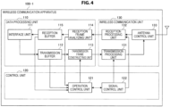
- FIG. 4 is a block diagram illustrating an example of a schematic functional configuration of the wireless communication apparatus 100-1 according to the first embodiment of the present disclosure.
- the interface unit 111 is an interface that is connected with the other functional components other than the above-described functional components in the AP 10-1, etc. Specifically, the interface unit 111 performs reception of transmission data from other functional components, provision of reception data to other functional components, or the like.
- the transmission buffer 112 stores data to be transmitted. Specifically, the transmission buffer 112 stores data obtained through the interface unit 111.
- the transmission frame constructing unit 113 generates a frame to be transmitted. Specifically, the transmission frame constructing unit 113 generates a frame on the basis of data stored in the transmission buffer 112 or control information set by the control unit 120.
- the control information may be information such as resource information related to a trigger frame which will be described later.
- the transmission frame constructing unit 113 generates a frame (or a packet) from data, and performs, for example, a process of adding a MAC header for media access control (MAC) and an error detection code to a generated frame.
- MAC media access control
- the reception frame analyzing unit 114 analyzes a received frame. Specifically, the reception frame analyzing unit 114 performs determination of a destination of a frame received by the wireless communication unit 130 and acquisition of data or control information included in the frame. For example, the reception frame analyzing unit 114 acquires data or the like by performing analysis of a MAC header, detection and correction of a code error, a reorder process, or the like on the received frame.
- the control unit 120 includes an operation control unit 121 and a signal control unit 122 as illustrated in FIG. 4 .
- the operation control unit 121 performs operation control on wireless communication. Specifically, the operation control unit 121 controls the occurrence of communication. For example, when a communication connection request occurs, the operation control unit 121 causes the data processing unit 110 to generate frames related to a connection process such as an association process or an authentication process. Further, when a transmission request of a trigger frame which will be described later occurs, the operation control unit 121 causes the data processing unit 110 to generate the trigger frame.
- the operation control unit 121 controls frame generation on the basis of a storage state of data in the transmission buffer 112, an analysis result of a reception frame, or the like. For example, in a case where data is stored in the transmission buffer 112, the operation control unit 121 instructs the transmission frame constructing unit 113 to generate a data frame in which the data is stored. Further, in a case where reception of the data frame is detected by the reception frame analyzing unit 114, the operation control unit 121 instructs the transmission frame constructing unit 113 to generate an ACK frame serving as a response to the data frame.
- the operation control unit 121 manages resources used in frame transmission. Specifically, the operation control unit 121 manages resource information which will be described later. For example, the operation control unit 121 decides a resource unit in the case of the AP 10-1 and registers a resource unit to be notified of in the case of the STA 20-1.
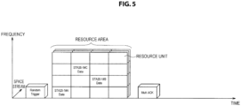
- the signal control unit 122 controls an operation of the wireless communication unit 130. Specifically, the signal management unit 122 controls transmission and reception processes of the wireless communication unit 130. For example, in the case of the STA 20-1, the signal control unit 122 causes the wireless communication unit 130 to perform UL transmission using some resources (one or more resource units) in a resource area which will be described later on the basis of an instruction given by the operation control unit 121.
- the wireless communication unit 130 includes a transmission processing unit 131, a reception processing unit 132, and an antenna control unit 133 as illustrated in FIG. 4 .
- the transmission processing unit 131 performs a frame transmission process. Specifically, the transmission processing unit 131 generates a signal to be transmitted on the basis of the frame provided from the transmission frame constructing unit 113. More specifically, the transmission processing unit 131 generates a signal related to the UL frame on the basis of resources instructed by the signal control unit 122. For example, the transmission processing unit 131 generates a symbol stream by performing encoding, interleaving, and modulation on the frame provided from the data processing unit 110, for example, according to a coding and modulation scheme set by the control unit 120. The transmission processing unit 131 converts a signal related to the symbol stream obtained by the process at the previous stage into an analog signal, and performs amplification, filtering, and frequency up-conversion on the analog signal.
- the size of the resource area may be smaller than that of the resource area illustrated in FIG. 5 .
- the number of STAs 20-1 having the data transmission request may be estimated on the basis of a result of communication with the STA 20-1 which has been performed at a previous point in time.
- the AP 10-1 decides the resource area (step S302). Specifically, the control unit 120 decides the attribute information of the STA 20-1 serving as a transmission target of the response UL frame, and decides the size of the resource unit on the basis of the decided attribute information, that is, content of the UL transmission. Then, the control unit 120 decides the resource area available for the UL transmission on the basis of the estimated number of STAs 20-1 corresponding to the attribute information and the size of the resource unit.
- the AP 10-1 generates the trigger frame for the apparatus having the data transmission request (step S304). Specifically, the control unit 120 sets only the STAs 20-1 having the ULR as a response target, and causes the data processing unit 110 to generate the trigger frame including the resource information in which the decided resource unit is specified.
- the AP 10-1 transmits the trigger frame to the STA 20-1 (step S306).
- the wireless communication unit 130 transmits the generated trigger frame to each of the STAs 20-1.
- the AP 10-1 performs the reception setting on the basis of the resource area (step S308). Specifically, the control unit 120 causes the wireless communication unit 130 to perform the reception setting so that the ULR frame is received within the decided resource area.
- the AP 10-1 is on standby until the ULR frame is received (step S310).
- the wireless communication unit 130 is on standby without changing the set communication parameter until the ULR frame is received.
- the AP 10-1 Upon receiving the ULR frame, the AP 10-1 transmits the UL transmission permission frame to the STA 20-1 (step S312). Specifically, when the ULR frame is received by the wireless communication unit 130, the data processing unit 110 acquires the UL transmission schedule information included in the ULR frame. Then, the control unit 120 allocates resources to the transmission source of the ULR frame on the basis of the UL transmission schedule information, and generates the resource allocation information. Then, the control unit 120 causes the data processing unit 110 to generate the UL transmission permission frame including the resource allocation information, and the generated UL transmission permission frame is transmitted through the wireless communication unit 130.
- the control unit 120 causes the wireless communication unit 130 to perform the reception setting on the basis of the resource allocation information so that the ULD frame is received.
- the AP 10-1 Upon receiving the ULD frame, the AP 10-1 transmits the confirmation response frame to the STA 20-1 (step S316). Specifically, when the ULD frame is received by the wireless communication unit 130, the control unit 120 causes the data processing unit 110 to generate the confirmation response frame to the ULD frame, and the generated confirmation response frame is transmitted through the wireless communication unit 130. Note that, in a case where no ULD frame is received, the confirmation response frame is not transmitted.
- FIG. 9 is a flowchart conceptually illustrating a process of the STA 20-1 according to the present embodiment.
- the STA 20-1 determines whether or not its own apparatus has the data transmission request (step S404). Specifically, when the trigger frame is received by the wireless communication unit 130, the data processing unit 110 acquires the resource information included in the trigger frame and the attribute information of the STA 20-1 serving as the UL transmission target. Then, in a case where an attribute indicated by the attribute information indicates that there is the data transmission request, the control unit 120 determines whether or not its own apparatus has the data transmission request. For example, the control unit 120 performs the determination on the basis of the presence or absence of data in the transmission buffer 112.
- the STA 20-1 selects the resource unit (step S406). Specifically, when its own apparatus is determined to have the data transmission request, the control unit 120 selects the resource unit on the basis of the resource information acquired from the trigger frame.
- the STA 20-1 transmits the ULR frame to the AP 10-1 using the resource unit (step S408).
- the control unit 120 causes the wireless communication unit 130 to perform the transmission setting on the basis of the selected resource unit.
- the control unit 120 causes the data processing unit 110 to generate the ULR frame including the UL transmission schedule information. Then, the generated ULR frame is transmitted through the wireless communication unit 130.
- the STA 20-1 determines whether or not the UL transmission permission frame has been received (step S410). Specifically, the control unit 120 determines whether or not the UL transmission permission frame has been received within a predetermined period of time from the transmission of the ULR frame. When the UL transmission permission frame is determined not to have been received within the predetermined period of time, the control unit 120 regards the UL transmission as not being permitted, and ends the process.
- the STA 20-1 Upon receiving the UL transmission permission frame, the STA 20-1 transmits the ULD frame to the AP 10-1 (step S412). Specifically, when the UL transmission permission frame is received by the wireless communication unit 130, the data processing unit 110 acquires the resource allocation information that is included in the UL transmission permission frame and addressed to its own apparatus. Then, the control unit 120 causes the wireless communication unit 130 to perform the transmission setting on the basis of the acquired resource allocation information. The control unit 120 causes the data processing unit 110 to generate the ULD frame. Then, the generated ULD frame is transmitted through the wireless communication unit 130.
- the STA 20-1 determines whether or not the confirmation response frame has been received (step S414). Specifically, the control unit 120 determines whether or not the confirmation response frame has been received within a predetermined period of time from the transmission of the ULD frame. When the confirmation response frame is determined not to have been received within the predetermined period of time, the control unit 120 regards the transmission of the ULD frame as having failed, and causes the process to return to step S402. In a case where the confirmation response frame has been received within the predetermined period of time, the process ends.
- the AP 10-1 transmits the first frame including the resource information in which resources selectable as uplink resources from a plurality of resources are specified and the attribute information related to transmission of the second frame, and receives the response frame transmitted as the response to the first frame.
- the STA 20-1 transmits the first frame including the resource information in which resources selectable as uplink resources from a plurality of resources are specified and the attribute information related to transmission of the response frame, and transmits the second frame as the response to the first frame. For this reason, only transmission of a specific response UL frame is performed on the basis of the attribute information, and thus resources used for the response UL frame transmitted in the UL communication of the random access scheme are reduced. As a result, a possibility that frame collision will occur is lower than in a case where an arbitrary STA 20-1 transmits the UL frame, and it is possible to suppress a decrease in the communication efficiency of the UL communication of the random access scheme.
- the second frame is transmitted using at least one resource selected from the selectable resources specified in the resource information on the basis of the attribute information related to the transmission of the second frame.
- the response UL frame is transmitted within the range of the selected resource unit, and thus it is possible to reduce the possibility that the resources of the response UL frames will overlap and more reliably reduce the possibility that the UL frames will collide.
- the AP 10-1 decides the resource area on the basis of the decided attribute of the frame.
- the control unit 120 decides the resource unit on the basis of the size of the frame specified from the decided type of frame.
- the control unit 120 decides the resource area on the basis of the estimated number of transmissions of the corresponding type of frame and the size of the resource unit.
- the AP 10-1 transmits the trigger frame including the resource information and the frame attribute information to the STA 20-1.
- the control unit 120 causes the data processing unit 110 to generate the trigger frame including the resource information in which a group of decided resource units is specified and the frame attribute information. Then, the generated trigger frame is transmitted through the wireless communication unit 130.
- the STA 20-1 that has received the trigger frame determines the presence or absence of the transmission of the response UL frame on the basis of the frame attribute information. Specifically, the control unit 120 determines whether or not the attribute of the UL frame that is scheduled to be transmitted corresponds to the attribute of the response UL frame. For example, in a case where the type of frame indicated by the frame attribute information is the control frame, the control unit 120 determines whether or not a type of UL frame that is scheduled to be transmitted is the control frame.
- the STA 20-1 transmits the response UL frame to the AP 10-1 using the resource unit selected from the resource information.
- the control unit 120 randomly selects the resource unit from a group of resource units specified in the resource information. Then, the control unit 120 causes the wireless communication unit 130 to perform the transmission setting on the basis of the selected resource unit, and causes the data processing unit 110 to generate the control frame serving as the response UL frame. Then, the generated control frame is transmitted through the wireless communication unit 130.
- the control unit 120 randomly selects the resource unit from a group of resource units specified in the resource information. Then, the control unit 120 causes the wireless communication unit 130 to perform the transmission setting on the basis of the selected resource unit, and causes the data processing unit 110 to generate the control frame serving as the response UL frame. Then, the generated control frame is transmitted through the wireless communication unit 130.
- the control frame is transmitted from each of the STAs 20-1#A to 20-1#D.
- the control frame transmitted from the STA 20-1#C and the control frame transmitted from the STA 20-1#D undergo the frequency division multiplexing.
- FIG. 11 is a diagram illustrating an example of a configuration of the trigger frame according to the first modified example of the present embodiment.
- the trigger frame has substantially the same field configuration as the trigger frame according to the first embodiment, but information stored in some fields differs as illustrated in FIG. 11 .
- Information (the frame attribute information) indicating an attribute of the response UL frame serving as the response to the trigger frame is stored in the allowed access field.
- information frame type indicating a type of frame may be stored in the allowed access field as illustrated in FIG. 11 .
- the attribute information related to the transmission of the second frame includes information related to the attribute of the second frame.
- the STA 20-1 transmits the frame in which the attribute of the frame corresponds to the attribute of the second frame as the second frame.
- the attribute of the second frame includes a type of frame.
- the size of the frame is roughly specified in accordance with a type of frame, and so the size of the resource unit, that is, the resources secured for the UL transmission, can be appropriately adjusted, and the resource use efficiency can be improved.
- the AP 10-1 may collect information of the other STAs 20-1 using the trigger frame instead of or in addition to the above-described information related to UL transmission traffic of the STA 20-1.
- the attribute information of the STA 20-1 that transmits the response UL frame which is included in the trigger frame includes information related to a communication state of the STA 20-1.
- the information related to the communication state of the STA 20-1 there is information related to communication quality.
- the AP 10-1 stores a threshold value of a packet error rate (PER) in the random access type field of the trigger frame as the attribute information of the STA 20-1 that transmits the response UL frame. Then, the AP 10-1 transmits the trigger frame to the STA 20-1.
- PER packet error rate
- the STA 20-1 that has received the trigger frame determines whether or not the PER of its own apparatus is equal to or higher than the threshold value of the PER included in the trigger frame. In a case where the PER is determined to be equal to or higher than the threshold value, the STA 20-1 randomly selects the resource unit from a group of resource units specified in the resource information included in the trigger frame. Then, the STA 20-1 transmits the response UL frame including the information indicating the STA ID of its own apparatus using the selected resource unit. The STA 20-1 may transmit the response UL frame including the PER of its own apparatus.
- the information related to the communication state of the STA 20-1 there is information related to a state of a communication channel.
- the AP 10-1 stores a predetermined value of an index included in a channel state information (CSI) report in the random access type field of the trigger frame as the frame attribute information of the response UL frame. Then, the AP 10-1 transmits the trigger frame to the STA 20-1.
- CSI channel state information
- the STA 20-1 that has received the trigger frame determines whether or not a value of an index included in the CSI report of its own apparatus satisfies a condition for the predetermined value included in the trigger frame. In a case where the condition is determined to be satisfied, the STA 20-1 randomly selects the resource unit from a group of resource units specified in the resource information included in the trigger frame. Then, the STA 20-1 transmits the response UL frame including the information indicating the STA ID of its own apparatus and the CSI report using the selected resource unit.
- the response UL frame may include information different from information related to the communication state serving as the transmission condition of the response UL frame. For example, information indicating a received signal strength indicator (RSSI) or the like may be included in the response UL frame including the PER.
- RSSI received signal strength indicator
- the attribute information of the transmission apparatus performing the transmission of the second frame includes information related to the communication state of the transmission apparatus.
- the incidence of the frame collision in the transmission of the information related to the communication state of the STA 20-1 is suppressed, and the information can be efficiently collected.
- the communication state includes the information related to the communication quality.
- the information related to the communication quality is efficiently collected, and the communication quality can be improved sooner, and the communication efficiency can be improved.
- the communication quality is improved.
- the communication quality of the multicast communication can be improved early on.
- the communication state includes the information related to the state of the communication channel.
- the information related to the state of the communication channel is efficiently collected, the communication parameter in accordance with the state of the communication channel is set sooner, and the communication quality and the communication efficiency can be improved.
- the second frame includes information related to content of the communication state of the transmission apparatus.
- an amount of information is increased, and thus the AP 10-1 can take various actions in order to improve the communication state.
- AP 10-1 and the STA 20-1 have been described above.
- an AP 10-2 and an STA 20-2 (hereinafter, also referred to as an "AP 10-2, etc.") according to the second embodiment of the present disclosure will be described.
- a configuration of the AP 10-2, etc. according to a second embodiment of the present disclosure is substantially the same as the configuration of the AP 10-1, etc. according to the first embodiment, and thus a description thereof is omitted.
- the control unit 120 decides the size of the resource unit on the basis of the size of the ULR frame. For example, the control unit 120 decides resources of the size corresponding to the size of the ULR frame as the resource unit.
- the size of the resource unit may be larger than the size of the ULR frame.
- the AP 10-2 decides the sub area that is at least a part of the resource area. Specifically, the control unit 120 decides the sub area on the basis of information (hereinafter, also referred to as a "transmission setting condition") associated with the transmission of the UL frame related to the response UL frame. More specifically, the control unit 120 acquires the transmission setting condition, and decides the size of resources corresponding to the acquired transmission setting condition. Then, the control unit 120 decides a group of resource units in the resource area corresponding to the decided size of resources as the sub area.
- a transmission setting condition information associated with the transmission of the UL frame related to the response UL frame. More specifically, the control unit 120 acquires the transmission setting condition, and decides the size of resources corresponding to the acquired transmission setting condition. Then, the control unit 120 decides a group of resource units in the resource area corresponding to the decided size of resources as the sub area.
- the transmission setting condition may be a condition related to the attribute of the UL frame.
- the attribute of the UL frame there is a type of frame or a size of data for the UL frame.
- the type of frame there is a type of MAC frame such as a control frame such as power save polling, a management frame such as a probe request, or a data frame.
- the type of frame may be any other type defined in a standard or may be a type that is defined uniquely, similarly to the first embodiment.
- the size of data may be indicated by a data length, a range of a data length, an index corresponding thereto, or the like.
- the transmission setting condition may be a condition related to redundancy of communication of the UL frame.
- a condition related to redundancy of communication there is a condition including at least one of a modulation scheme and a coding rate.
- MCS modulation and coding scheme
- the transmission setting condition may be a condition related to the communication state of the transmission apparatus of the UL frame.
- the condition related to the communication state of the transmission apparatus there is a condition related to radio wave propagation characteristics.
- the condition related to the radio wave propagation characteristics there is a condition related to the RSSI or a received field strength.
- the condition related to the radio wave propagation characteristics may be a condition related to the PER or a bit error rate (BER) instead of or in addition to the RSSI.
- the AP 10-2 notifies each of the STAs 20-2 of information about the decided sub area. Specifically, the AP 10-2 transmits a trigger frame including information (hereinafter, also referred to as "sub area information") in which the sub area is specified from the resource area including the resource unit selectable as the UL resources. More specifically, the control unit 120 decides the sub area information, and causes the data processing unit 110 to generate the trigger frame including the sub area information. Then, the wireless communication unit 130 transmits the generated trigger frame. The trigger frame is transmitted for each channel serving as a channel bonding target. Thus, the STA 20-2 that has received the trigger frame can detect the channel serving as the channel bonding target usable by its own apparatus.
- sub area information information in which the sub area is specified from the resource area including the resource unit selectable as the UL resources.
- the control unit 120 decides the sub area information, and causes the data processing unit 110 to generate the trigger frame including the sub area information.
- the wireless communication unit 130 transmits the generated trigger frame.
- the trigger frame is transmitted for
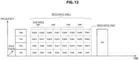
- the AP 10-2 transmits trigger frames TF#1 to TF#4 illustrated in FIG. 12 as the trigger frame using four channels serving as the channel bonding target.
- the TF is transmitted even through a channel other than the primary channel so that the TF is received even by the STA 20-2 that does not support channel bonding.
- the TFs are subject to the frequency division multiplexing in units of predetermined bandwidths, for example, in units of 20 MHz and transmitted through all available channels.
- FIG. 12 is a diagram illustrating an example of a configuration of the trigger frame according to the present embodiment.
- the trigger frame includes fields such as a PHY header, a MAC Header, a resource unit allocation parameter, and an FCS as illustrated in FIG. 13 .
- the MAC header field includes fields such as frame control, duration/ID, a transmitter address (TA), and a receiver address (RA). Since it is desirable that the trigger frame be received by many STAs 20-2, a broadcast address may be stored in the RA field.
- Information corresponding to any one of the transmission setting conditions is stored in the condition parameter field.
- parameters 0x01 to 0x04 defined by 2-byte codes are prepared as information corresponding to types of frame as illustrated in FIG. 14 .
- the parameters 0x01 to 0x04 correspond to a probe request, power save polling, any other control frame, and a data frame.
- parameters 0x09 to 0x0C are prepared as information corresponding to data sizes for the UL frame.
- the parameters 0x09 to 0x0C correspond to 1 to 127 octets, 128 to 1023 octets, and 1K to 1M octets, and more than 1M octets as the size of data accumulated in the transmission buffer 112.
- parameters 0x10 and 0x11 are prepared as information corresponding to the RSSIs measured by the STA 20-2.
- the parameters 0x10 and 0x11 correspond to an RSSI weaker than a threshold value and an RSSI stronger than the threshold value.
- the RSSI may be a specific numerical value of the threshold value.
- parameters 0x20 to 0x22 are prepared as information corresponding to a modulation scheme and a coding rate used by the STA 20-2.
- the parameters 0x20 to 0x22 correspond to binary phase shift keying (BPSK)/quadrature phase shift keying (QPSK), 16 quadrature amplitude modulation (QAM)/64QAM, and 256QAM as the MCS.
- BPSK binary phase shift keying
- QPSK quadrature amplitude modulation
- MCS 16 quadrature amplitude modulation
- condition parameter field information corresponding to a combination of a plurality of transmission setting conditions may be stored in the condition parameter field.
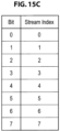
- FIGS. 15A to 15C are diagrams illustrating examples of information included in the frequency map, the timing map, and the spatial map field of the trigger frame to be transmitted according to the present embodiment.
- the AP 10-2 Upon receiving a signal related to the response UL frame, the AP 10-2 stores the sub area to which the signal belongs. For example, when the signal of the response UL frame, for example, a preamble, is received by the wireless communication unit 130, the control unit 120 specifies the sub area on the basis of the time, the frequency, and the space stream related to reception of the preamble. Then, the control unit 120 stores the specified sub area. As a result, the control unit 120 detects the presence of the response UL frame. Thus, the presence or absence of the transmission of the response UL frame is detected regardless of the presence or absence of the reception of the response UL frame, and thus an action can be performed on the STA 20-2 without waiting for the reception of the response UL frame.
- the control unit 120 specifies the sub area on the basis of the time, the frequency, and the space stream related to reception of the preamble. Then, the control unit 120 stores the specified sub area. As a result, the control unit 120 detects the presence of the response UL frame
- the AP 10-2 Upon receiving the response UL frame, the AP 10-2 stores the sub area to which the response UL frame belongs. For example, after the preamble is received by the wireless communication unit 130, when the response UL frame is successfully received, the control unit 120 specifies the sub area on the basis of the time, the frequency, and the space stream related to the reception of the response UL frame. Then, the control unit 120 stores the specified sub area. The control unit 120 associates the specified sub area with the response UL frame, and stores the association.
- control unit 120 may specify the sub area related to the signal for the main body of the response UL frame and store the specified sub area. For example, in a case where an error is detected on the basis of a cyclic redundancy check (CRC) of the response UL frame, the sub area related to signal detection of the response UL frame is stored.
- CRC cyclic redundancy check
- the AP 10-2 Upon receiving the response UL frame, the AP 10-2 transmits a frame (hereinafter, also referred to as a "response DL frame") serving as the response to the response UL frame. Specifically, when the signal for the response UL frame is received, the AP 10-2 transmits the confirmation response frame for the response UL frame. For example, after the waiting for the response UL frame ends, the control unit 120 generates the ACK information corresponding to the sub area on the basis of the storage of the sub area, and causes the data processing unit 110 to generate the ACK frame including the ACK information. Then, the generated ACK frame is transmitted through the wireless communication unit 130.
- the ACK frame may be a multi ACK frame including a plurality of pieces of ACK information.
- the control unit 120 After the waiting for the response UL frame ends, the control unit 120 generates the ACK information addressed to the transmission source of the response UL frame on the basis of the association of the sub area and the response UL frame, and causes the data processing unit 110 to generate the ACK frame including the ACK information. Then, the generated ACK frame is transmitted through the wireless communication unit 130.
- the ACK frame may be generated separately from the ACK frame including the ACK information corresponding to the sub area, or both pieces of ACK information may be included in one ACK frame.
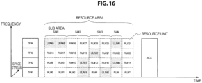
- the ACK frames are transmitted through all available channels, for example, as illustrated in FIG. 16 .
- the response DL frame may be a frame different from the confirmation response frame.
- the AP 10-2 transmits a communication connection response frame as the response to the response UL frame.
- the AP 10-2 transmits a probe response frame to the STA 20-2 serving as the transmission source of the probe request frame.
- the STA 20-2 selects the sub area on the basis of the sub area information.
- the control unit 120 specifies the sub area corresponding to the satisfied transmission setting condition among the transmission setting conditions included in the sub area information.
- the transmission setting conditions corresponding to the sub areas SA#1 to SA#4 illustrated in FIG. 16 are considered to be that the data size is 128 to 1023 octets, the data size is 1K to 1M octets, the RSSI is weak, and it is the probe request.
- values of the condition parameter fields included in the SA field of the trigger frame are 0x0A, 0x0B, 0x10, and 0x01.
- the control unit 120 acquires the size of data accumulated in the transmission buffer 112, and specifies the sub area of the parameter to which the acquired data size corresponds. For example, in a case where the acquired data size is 255 octets, the control unit 120 selects the sub area SA#1. Further, in a case where the RSSI of its own apparatus is weak, that is, lower than the threshold value, the control unit 120 selects the sub area SA#3. Further, in a case where a type of frame whose UL transmission is scheduled is the probe request, the control unit 120 selects the sub area SA#4.
- a plurality of sub areas may be selected.
- the control unit 120 selects both of the sub areas SA#1 and SA#3 in a case where the RSSI of its own apparatus is lower than the threshold value, and the size of data stored in the transmission buffer 112 is 255 octets.
- the STA 20-2 selects the resource unit from the selected sub area. Specifically, the control unit 120 selects the resource unit used for the UL transmission among a group of resource units included in the selected sub area. For example, in a case where the sub area SA#4 illustrated in FIG. 16 is selected, the control unit 120 selects at least one resource unit from resource units RU#6, RU#14, RU#22 and RU#30 included in the sub area SA#4. In the example of FIG. 16 , in the sub area SA#4, the STA 20-2#1 selects the resource unit RU#30, and the STA 20-2#4 selects the resource unit RU#14.
- a plurality of resource units may be selected.
- the control unit 120 selects a plurality of resource units from the sub area on the basis of the plurality of channels. For example, in a case where its own apparatus supports the channel bonding, the control unit 120 of the STA 20-2#3 selects the two resource units RU#3 and RU#11 corresponding to the channels usable by its own apparatus in the sub area SA#2 illustrated in FIG. 16 .
- the control unit 120 may select a plurality of resource units from the sub area. For example, in a case where a priority of data related to the UL frame that is scheduled to be transmitted is higher than those of other data, the control unit 120 of the STA 20-2#5 selects the two resource units RU#24 and RU#25 in the sub area SA#1 illustrated in FIG. 16 .
- control unit 120 may select a resource unit of a different frequency channel from the resource units selected by the other STAs 20-2. For example, the control unit 120 causes the wireless communication unit 130 to scan each frequency channel at an arbitrary timing. Then, the control unit 120 causes the wireless communication unit 130 to store transmission frequencies previously used by the other STAs 20-2 on the basis of the scanning result, and specifies frequency channels that are not used by the other STAs 20-2 using the previously used transmission frequencies.
- the AP 10-2 determines whether or not the trigger frame has been constructed through all use channels (step S522). Specifically, the control unit 120 determines whether or not an instruction to generate the trigger frame for all the frequency channels indicated by the acquired information has been given. In a case where the trigger frame has not been constructed for any one of the frequency channels, the process returns to step S520.
- FIG. 19 is a flowchart conceptually illustrating the communication process of the AP 10-2 with the STA 20-2 according to the present embodiment.
- the AP 10-2 determines whether or not a random access time has arrived (step S602). Specifically, the control unit 120 determines whether or not the random access time decided in its own apparatus has arrived.
- the AP 10-2 acquires the trigger frame (step S604). Specifically, when the random access time is determined to have arrived, the control unit 120 causes the data processing unit 110 to acquire the trigger frame that is previously constructed.
- the AP 10-2 determines whether or not a wireless transmission path is available (step S606). Specifically, the control unit 120 determines whether or not the wireless transmission path is empty using a carrier sense or the like.
- the AP 10-2 transmits the trigger frame to the STA 20-2 (step S608). Specifically, when the wireless transmission path is determined to be empty, the control unit 120 causes the wireless communication unit 130 to transmit the acquired trigger frame.
- the AP 10-2 performs the reception setting of the response UL frame (step S610). Specifically, after the trigger frame is transmitted, the control unit 120 causes the wireless communication unit 130 to perform the reception setting on the basis of the sub area information included in the trigger frame so that the response UL frame transmitted from the STA 20-2 is received.
- the AP 10-2 determines whether or not it is within a response UL frame reception period of time (step S612). Specifically, the control unit 120 determines whether or not a predetermined period of time has elapsed from the transmission of the trigger frame.
- the AP 10-2 When it is determined to be within the response UL frame reception period of time, the AP 10-2 is on standby until the signal is detected (step S614). Specifically, in a case where the predetermined period of time is determined not to have elapsed from the transmission of the trigger frame, the control unit 120 is continuously on standby for the signal detection.
- the AP 10-2 stores the sub area related to the signal detection (step S616). Specifically, when the signal is detected by the wireless communication unit 130, the control unit 120 specifies the sub area on the basis of the time, the frequency, and the space stream in which the signal is detected. Then, the control unit 120 stores information indicating the specified sub area in a storage unit with which the AP 10-2 is separately equipped.
- the AP 10-2 determines whether or not the response UL frame has been successfully received (step S618). Specifically, the control unit 120 determines whether or not the response UL frame is received by the wireless communication unit 130 and stored in a reception buffer.
- the AP 10-2 stores the sub area related to the reception of the response UL frame (step S620). Specifically, when the response UL frame is received, the control unit 120 specifies the sub area on the basis of the time, the frequency, and the space stream in which the response UL frame is received. Then, the control unit 120 causes information indicating the specified sub area to be stored in a storage unit.
- the attribute information associated with the transmission of the uplink frame related to the response frame includes the information related to the attribute of the uplink frame.
- the attribute of the frame is distinguished by the sub area, and so it is possible to easily detect the number of transmissions of each type of UL frame.
- the attribute information associated with the transmission of the uplink frame includes the size of data to be transmitted.
- the size of frame and the number of frames whose UL transmission is scheduled are specified, and so it is possible to appropriately allocate the resources for the UL transmission.
- the attribute information associated with the transmission of the uplink frame includes the information related to the redundancy of communication of the uplink frame.
- the information related to the redundancy of communication includes information related to at least one of a modulation scheme and a coding rate.
- the attribute information associated with the transmission of the uplink frame includes the information related to the communication state of the transmission apparatus of the uplink frame.
- the communication parameter setting or the resource allocation in the UL communication is performed in accordance with the communication state of the STA 20-2, and so it is possible to more reliably suppress the decrease in the communication efficiency in the UL communication.
- the information related to the communication state of the transmission apparatus includes the information related to the radio wave propagation characteristics.
- the information related to the radio wave propagation characteristics of the STA 20-2 is collected, and so the communication parameter or resource allocation suitable for the STA 20-2 can be performed.
- the AP 10-2 upon receiving the signal for the response frame, transmits the frame serving as the response to the response frame.
- the frame for example, the confirmation response frame
- the frame is transmitted to the STA 20-2 in accordance with the signal detection, and a notification indicating that the resource units overlap may be given to the STA 20-2.
- the STA 20-2 retransmits the response UL frame using another resource unit, and it is possible to succeed in the transmission of the response UL frame.
- the STA 20-2 transmits the response frame using a plurality of wireless communication resources selected from the sub area on the basis of the plurality of channels.
- the notification indicating that the STA 20-2 supports the channel bonding is given to the AP 10-2, and the resources are allocated for the UL transmission through a plurality of channels, and so it is possible to improve the communication efficiency in the UL transmission.
- the STA 20-2 transmits the response frame using a plurality of wireless communication resources selected from the sub area.
- resource allocation corresponding to a plurality of resource units is performed in accordance with the importance of data whose UL transmission is scheduled, and so a transmission success rate of data can be improved.
- the STA 20 may be realized as mobile terminals such as smartphones, tablet PCs (Personal Computers), notebook PCs, portable game terminals, or digital cameras, fixed-type terminals such as television receivers, printers, digital scanners, or network storages, or car-mounted terminals such as car navigation devices.
- the STA 20 may be realized as terminals that perform M2M (Machine to Machine) communication (also referred to as MTC (Machine Type Communication) terminals) such as smart meters, vending machines, remotely controlled surveillance devices, or POS (Point Of Sale) terminals.
- M2M Machine to Machine
- MTC Machine Type Communication
- the STA 20 may be wireless communication modules mounted in such terminals (for example, integrated circuit modules configured by one die).
- the AP 10 may be realized as a wireless LAN access point (also referred to as a wireless base station) which has a router function or does not have a router function.
- the AP 10 may be realized as a mobile wireless LAN router.
- the AP 10 may also be a wireless communication module (for example, an integrated circuit module configured with one die) mounted on the device.
- the camera 906 has an image sensor, for example, a CCD (Charge Coupled Device) or a CMOS (Complementary Metal Oxide Semiconductor), to generate captured images.
- the sensor 907 can include a sensor group including, for example, a positioning sensor, a gyro sensor, a geomagnetic sensor, an acceleration sensor, and the like.
- the microphone 908 converts sounds input to the smartphone 900 into audio signals.
- the input device 909 includes, for example, a touch sensor that detects touches on a screen of the display device 910, a key pad, a keyboard, buttons, switches, and the like, to receive manipulations or information inputs from a user.
- the display device 910 has a screen such as a liquid crystal display (LCD), or an organic light emitting diode (OLED) display to display output images of the smartphone 900.
- the speaker 911 converts audio signals output from the smartphone 900 into sounds.
- the wireless communication interface 913 supports one or more wireless LAN standards of IEEE 802.11a, 11b, 11g, 11n, 11ac, and 11ad, to execute the wireless LAN communication.
- the wireless communication interface 913 can communicate with another device via a wireless LAN access point in an infrastructure mode.
- the wireless communication interface 913 can directly communicate with another device in a direct communication mode such as an ad hoc mode or Wi-Fi Direct (registered trademark).
- Wi-Fi Direct is different from the ad hoc mode, and thus one of two terminals operates as an access point. However, communication is performed directly between the terminals.
- the wireless communication interface 913 can typically include a baseband processor, an RF (Radio Frequency) circuit, a power amplifier, and the like.
- the wireless communication interface 913 may be a single-chip module on which a memory that stores a communication control program, a processor that executes the program, and a relevant circuit are integrated.
- the wireless communication interface 913 may support another kind of wireless communication scheme such as a cellular communication scheme, a short-range wireless communication scheme, or a proximity wireless communication scheme in addition to the wireless LAN scheme.
- the antenna switch 914 switches a connection destination of the antenna 915 for a plurality of circuits (for example, circuits for different wireless communication schemes) included in the wireless communication interface 913.
- the antenna 915 has a single or a plurality of antenna elements (for example, a plurality of antenna elements constituting a MIMO antenna), and is used for transmission and reception of wireless signals from the wireless communication interface 913.
- the smartphone 900 may include a plurality of antennas (for example, antennas for a wireless LAN or antennas for a proximity wireless communication scheme, or the like), without being limited to the example of FIG. 21 .
- the antenna switch 914 may be omitted from the configuration of the smartphone 900.
- the bus 917 connects the processor 901, the memory 902, the storage 903, the externally connected interface 904, the camera 906, the sensor 907, the microphone 908, the input device 909, the display device 910, the speaker 911, the wireless communication interface 913, and the auxiliary controller 919 to one another.
- the battery 918 supplies electric power to each of the blocks of the smartphone 900 shown in FIG. 21 via power supply lines partially indicated by dashed lines in the drawing.
- the auxiliary controller 919 causes, for example, necessary minimum functions of the smartphone 900 to be operated in a sleep mode.
- the data processing unit 110, the control unit 120 and the wireless communication unit 130 described above with reference to FIG. 4 may be implemented in the wireless communication interface 913. At least some of the functions may be implemented in the processor 901 or the auxiliary controller 919.
- the control unit 120 causes the data processing unit 110 to generate the response UL frame serving as the response to the trigger frame on the basis of the resource information and the attribute information included in the received trigger frame, and causes the wireless communication unit 130 to transmit the generated response UL frame.
- the number of frames transmitted in the UL communication of the random access scheme performed by the smartphone 900 is reduced, the frame collision is consequently suppressed and thus the decrease in the communication efficiency can be suppressed.
- control unit 120 causes the data processing unit 110 to generate the response UL frame serving as the response to the trigger frame on the basis of the sub area information included in the received trigger frame, and causes the wireless communication unit 130 to transmit the generated response UL frame.
- the ULR is efficiently detected in the UL communication of the random access scheme performed by the smartphone 900, and thus the decrease in the communication efficiency can be suppressed.
- the smartphone 900 may operate as a wireless access point (software AP) as the processor 901 executes the function of an access point at an application level.
- the wireless communication interface 913 may have the function of a wireless access point.
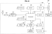
- FIG. 22 is a block diagram showing an example of a schematic configuration of a car navigation device 920 to which the technology of the present disclosure can be applied.
- the car navigation device 920 includes a processor 921, a memory 922, a GPS (Global Positioning System) module 924, a sensor 925, a data interface 926, a content player 927, a storage medium interface 928, an input device 929, a display device 930, a speaker 931, a wireless communication interface 933, an antenna switch 934, an antenna 935, and a battery 938.
- GPS Global Positioning System
- the processor 921 may be, for example, a CPU or an SoC controlling a navigation function and other functions of the car navigation device 920.
- the memory 922 includes a RAM and a ROM storing programs executed by the processor 921 and data.
- the GPS module 924 measures a position of the car navigation device 920 (for example, latitude, longitude, and altitude) using GPS signals received from a GPS satellite.
- the sensor 925 can include a sensor group including, for example, a gyro sensor, a geomagnetic sensor, a pneumatic sensor, and the like.
- the data interface 926 is connected to an in-vehicle network 941 via, for example, a terminal that is not illustrated to acquire data generated on the vehicle side such as car speed data.
Landscapes
- Engineering & Computer Science (AREA)
- Computer Networks & Wireless Communication (AREA)
- Signal Processing (AREA)
- Quality & Reliability (AREA)
- Mobile Radio Communication Systems (AREA)
Applications Claiming Priority (6)
| Application Number | Priority Date | Filing Date | Title |
|---|---|---|---|
| JP2015135465 | 2015-07-06 | ||
| EP16821079.7A EP3261397B1 (de) | 2015-07-06 | 2016-04-19 | Kommunikationsvorrichtung und kommunikationsverfahren |
| EP23189445.2A EP4294108B1 (de) | 2015-07-06 | 2016-04-19 | Uplink-kommunikation in drahtlosen lokalen netzwerken |
| EP20186800.7A EP3745800B1 (de) | 2015-07-06 | 2016-04-19 | Kommunikationsvorrichtung und kommunikationsverfahren |
| EP19177724.2A EP3557936B1 (de) | 2015-07-06 | 2016-04-19 | Kommunikationsvorrichtung und kommunikationsverfahren |
| PCT/JP2016/062368 WO2017006608A1 (ja) | 2015-07-06 | 2016-04-19 | 通信装置および通信方法 |
Related Parent Applications (4)
| Application Number | Title | Priority Date | Filing Date |
|---|---|---|---|
| EP19177724.2A Division EP3557936B1 (de) | 2015-07-06 | 2016-04-19 | Kommunikationsvorrichtung und kommunikationsverfahren |
| EP16821079.7A Division EP3261397B1 (de) | 2015-07-06 | 2016-04-19 | Kommunikationsvorrichtung und kommunikationsverfahren |
| EP23189445.2A Division EP4294108B1 (de) | 2015-07-06 | 2016-04-19 | Uplink-kommunikation in drahtlosen lokalen netzwerken |
| EP20186800.7A Division EP3745800B1 (de) | 2015-07-06 | 2016-04-19 | Kommunikationsvorrichtung und kommunikationsverfahren |
Publications (2)
| Publication Number | Publication Date |
|---|---|
| EP4583622A2 true EP4583622A2 (de) | 2025-07-09 |
| EP4583622A3 EP4583622A3 (de) | 2025-08-27 |
Family
ID=57685352
Family Applications (7)
| Application Number | Title | Priority Date | Filing Date |
|---|---|---|---|
| EP19175729.3A Active EP3565354B1 (de) | 2015-07-06 | 2016-04-19 | Kommunikationsvorrichtung und kommunikationsverfahren |
| EP19177724.2A Active EP3557936B1 (de) | 2015-07-06 | 2016-04-19 | Kommunikationsvorrichtung und kommunikationsverfahren |
| EP16821079.7A Active EP3261397B1 (de) | 2015-07-06 | 2016-04-19 | Kommunikationsvorrichtung und kommunikationsverfahren |
| EP19176342.4A Active EP3550924B1 (de) | 2015-07-06 | 2016-04-19 | Kommunikationsvorrichtung und kommunikationsverfahren |
| EP25178366.8A Pending EP4583622A3 (de) | 2015-07-06 | 2016-04-19 | Kommunikationsvorrichtung und kommunikationsverfahren |
| EP20186800.7A Active EP3745800B1 (de) | 2015-07-06 | 2016-04-19 | Kommunikationsvorrichtung und kommunikationsverfahren |
| EP23189445.2A Active EP4294108B1 (de) | 2015-07-06 | 2016-04-19 | Uplink-kommunikation in drahtlosen lokalen netzwerken |
Family Applications Before (4)
| Application Number | Title | Priority Date | Filing Date |
|---|---|---|---|
| EP19175729.3A Active EP3565354B1 (de) | 2015-07-06 | 2016-04-19 | Kommunikationsvorrichtung und kommunikationsverfahren |
| EP19177724.2A Active EP3557936B1 (de) | 2015-07-06 | 2016-04-19 | Kommunikationsvorrichtung und kommunikationsverfahren |
| EP16821079.7A Active EP3261397B1 (de) | 2015-07-06 | 2016-04-19 | Kommunikationsvorrichtung und kommunikationsverfahren |
| EP19176342.4A Active EP3550924B1 (de) | 2015-07-06 | 2016-04-19 | Kommunikationsvorrichtung und kommunikationsverfahren |
Family Applications After (2)
| Application Number | Title | Priority Date | Filing Date |
|---|---|---|---|
| EP20186800.7A Active EP3745800B1 (de) | 2015-07-06 | 2016-04-19 | Kommunikationsvorrichtung und kommunikationsverfahren |
| EP23189445.2A Active EP4294108B1 (de) | 2015-07-06 | 2016-04-19 | Uplink-kommunikation in drahtlosen lokalen netzwerken |
Country Status (14)
| Country | Link |
|---|---|
| US (5) | US10667300B2 (de) |
| EP (7) | EP3565354B1 (de) |
| JP (4) | JP6766810B2 (de) |
| KR (1) | KR102496937B1 (de) |
| CN (1) | CN107432012B (de) |
| AU (1) | AU2016288914B2 (de) |
| CA (1) | CA2979515C (de) |
| DE (1) | DE112016000968B4 (de) |
| MX (1) | MX2017012078A (de) |
| MY (1) | MY192130A (de) |
| PH (1) | PH12017501705B1 (de) |
| RU (1) | RU2718432C2 (de) |
| SG (2) | SG10201903704UA (de) |
| WO (1) | WO2017006608A1 (de) |
Families Citing this family (6)
| Publication number | Priority date | Publication date | Assignee | Title |
|---|---|---|---|---|
| JP6729582B2 (ja) | 2015-07-07 | 2020-07-22 | ソニー株式会社 | 通信装置および通信方法 |
| WO2017011744A1 (en) * | 2015-07-16 | 2017-01-19 | Atefi Ali | Apparatuses, methods, and computer-readable medium for communication in a wireless local area network |
| US10512047B2 (en) * | 2016-03-30 | 2019-12-17 | Intel IP Corporation | Access point (AP), station (STA) and method of multi-user (MU) location measurment |
| US10764877B2 (en) | 2016-05-06 | 2020-09-01 | Qualcomm Incorporated | Trigger frame in wireless local area network |
| WO2021217522A1 (zh) * | 2020-04-29 | 2021-11-04 | 华为技术有限公司 | 接入方法和装置以及通信系统 |
| CN113596927A (zh) * | 2020-04-30 | 2021-11-02 | 华为技术有限公司 | 无线通信传输方法及相关装置 |
Citations (2)
| Publication number | Priority date | Publication date | Assignee | Title |
|---|---|---|---|---|
| JP2015511077A (ja) | 2012-03-01 | 2015-04-13 | インターデイジタル パテント ホールディングス インコーポレイテッド | Wlanシステムにおけるマルチユーザ並列チャネルアクセス |
| WO2016028131A1 (ko) | 2014-08-22 | 2016-02-25 | 엘지전자(주) | 무선 통신 시스템에서 상향링크 다중 사용자 전송 방법 및 이를 위한 장치 |
Family Cites Families (49)
| Publication number | Priority date | Publication date | Assignee | Title |
|---|---|---|---|---|
| GB0714927D0 (en) * | 2007-08-01 | 2007-09-12 | Nokia Siemens Networks Oy | Resource allocation |
| US8155695B2 (en) | 2008-07-29 | 2012-04-10 | Sony Ericsson Mobile Communications Ab | Apparatus and method to improve WLAN performance in a dual WLAN modality environment |
| US8989106B2 (en) | 2009-02-27 | 2015-03-24 | Qualcomm Incorporated | Methods and apparatuses for scheduling uplink request spatial division multiple access (RSDMA) messages in an SDMA capable wireless LAN |
| US9357565B2 (en) | 2010-03-09 | 2016-05-31 | Qualcomm Incorporated | Multi-user uplink communication using EDCA with polling |
| US8526346B1 (en) * | 2010-04-28 | 2013-09-03 | Qualcomm Incorporated | Power save communication mechanism for wireless communication systems |
| TW201407973A (zh) | 2012-05-09 | 2014-02-16 | Interdigital Patent Holdings | 在無線區域網路及無線傳送接收單元中多使用者多輸入多輸出通訊 |
| WO2014014094A1 (ja) * | 2012-07-19 | 2014-01-23 | 日本電信電話株式会社 | 無線通信システム及び無線通信方法 |
| US9930678B2 (en) * | 2012-07-19 | 2018-03-27 | Qualcomm Incorporated | Multiplexing UEs with different TDD configurations and some techniques to mitigate UE-to-UE and base station-to-base station interference |
| EP2693673A1 (de) | 2012-08-01 | 2014-02-05 | Alcatel Lucent | Bit-Verschachteler für ein optischen Leitungsendgerät |
| US9455773B2 (en) * | 2013-07-15 | 2016-09-27 | Electronics And Telecommunications Research Institute | Uplink multi-user multiple-input and multiple-output (UL MU-MIMO) transmission request method in UL MU-MIMO communication |
| US9860174B2 (en) * | 2013-08-28 | 2018-01-02 | Qualcomm Incorporated | Methods and apparatus for acknowledgment of multi-user uplink wireless transmissions |
| US20150063190A1 (en) | 2013-08-28 | 2015-03-05 | Qualcomm Incorporated | Methods and apparatus for multiple user uplink |
| JP2015105199A (ja) | 2013-11-29 | 2015-06-08 | 住友電気工業株式会社 | 光ファイバおよび光ファイバ母材 |
| WO2015178566A1 (en) | 2014-05-18 | 2015-11-26 | Lg Electronics Inc. | Method and apparatus for transmitting uplink data in a wireless communication system |
| WO2015186887A1 (ko) * | 2014-06-02 | 2015-12-10 | 엘지전자 주식회사 | 프레임을 수신하는 방법 및 장치 |
| WO2016007126A1 (en) | 2014-07-07 | 2016-01-14 | Intel Corporation | Spin-transfer torque memory (sttm) devices having magnetic contacts |
| WO2016021831A1 (ko) * | 2014-08-07 | 2016-02-11 | 엘지전자(주) | 무선 통신 시스템에서 다중 사용자 전송 방법 및 이를 위한 장치 |
| US9942943B2 (en) | 2014-08-21 | 2018-04-10 | Lg Electronics Inc. | Method and apparatus for triggering uplink data in wireless LAN |
| JP6375816B2 (ja) | 2014-09-18 | 2018-08-22 | 日本精機株式会社 | 車両用周辺情報表示システム及び表示装置 |
| US9894641B2 (en) * | 2014-09-26 | 2018-02-13 | Qualcomm, Incorporated | Methods and apparatus for implementing multiple user uplink medium access control protocols in a wireless network |
| US9991995B2 (en) * | 2014-10-06 | 2018-06-05 | Newracom, Inc. | Multiuser signaling and access request mechanisms |
| KR20160045023A (ko) * | 2014-10-16 | 2016-04-26 | 뉴라컴 인코포레이티드 | 고효율 무선랜에서 상향링크 채널 액세스 방법 및 장치 |
| US9992746B2 (en) * | 2014-10-28 | 2018-06-05 | Qualcomm Incorporated | Uplink power control in multi-user unlicensed wireless networks |
| US9980292B2 (en) * | 2014-10-29 | 2018-05-22 | Mediatek Inc. | Contention based uplink orthogonal frequency-division multiple access (OFDMA) |
| US9992774B2 (en) * | 2014-11-11 | 2018-06-05 | Marvell World Trade Ltd. | Acknowledgment for multiple user communication in a WLAN |
| US10334571B2 (en) * | 2014-12-05 | 2019-06-25 | Marvell World Trade Ltd. | Trigger frame format for orthogonal frequency division multiple access (OFDMA) communication |
| EP3588888B1 (de) * | 2014-12-05 | 2021-03-10 | Lg Electronics Inc. | Datenübertragungsverfahren in drahtloskommunikationssystem und vorrichtung dafür |
| US10091822B2 (en) * | 2014-12-23 | 2018-10-02 | Mediatek Inc. | Allocation of uplink resources in orthogonal frequency-division multiple access (OFDMA) wireless networks |
| JP6470417B2 (ja) * | 2014-12-30 | 2019-02-13 | エルジー エレクトロニクス インコーポレイティド | 無線lanシステムにおけるトリガフレームの受信後の上りリンク伝送方法及び装置 |
| US9949285B2 (en) * | 2015-01-07 | 2018-04-17 | Futurewei Technologies, Inc. | System and method for digital communications with interference avoidance |
| US10257854B2 (en) * | 2015-02-02 | 2019-04-09 | Samsung Electronics Co., Ltd. | Management of uplink multi-user transmissions in wireless local area networks |
| US9930695B2 (en) * | 2015-02-03 | 2018-03-27 | Intel IP Corporation | Orthogonal frequency-division multiple access distributed channel access |
| US10111258B2 (en) * | 2015-02-13 | 2018-10-23 | Qualcomm Incorporated | Methods and systems for receiver initiated protection of a wireless communication exchange |
| WO2016154818A1 (zh) * | 2015-03-27 | 2016-10-06 | 华为技术有限公司 | 多站点接入方法、装置及系统 |
| US20160295624A1 (en) * | 2015-04-02 | 2016-10-06 | Samsung Electronics Co., Ltd | Methods and apparatus for resource pool design for vehicular communications |
| WO2016164912A1 (en) * | 2015-04-09 | 2016-10-13 | Marvell World Trade Ltd. | Contention-based orthogonal frequency division multiple access (ofdma) communication |
| WO2016167609A1 (ko) * | 2015-04-16 | 2016-10-20 | 엘지전자(주) | 무선 통신 시스템에서 채널 사운딩 방법 및 이를 위한 장치 |
| US10219274B2 (en) | 2015-04-23 | 2019-02-26 | Marvell World Trade Ltd. | Channel bonding operations in wireless communications |
| US9894653B2 (en) * | 2015-04-24 | 2018-02-13 | Intel IP Corporation | Apparatus, computer readable medium, and method for multi-user request-to-send and clear-to-send in a high efficiency wireless local-area network |
| US11082167B2 (en) * | 2015-04-29 | 2021-08-03 | Interdigital Patent Holdings, Inc. | Triggered transmission opportunity and multiple user ACK procedures in WLAN systems |
| US20160323424A1 (en) * | 2015-05-01 | 2016-11-03 | Qualcomm Incorporated | Null data packet frame structure for wireless communication |
| US10492223B2 (en) * | 2015-05-21 | 2019-11-26 | Newracom, Inc. | Channel access for multi-user communication |
| US10070458B2 (en) * | 2015-05-22 | 2018-09-04 | Newracom, Inc. | Resource request and allocation for uplink multi-user communication |
| ES2833536T3 (es) | 2015-05-27 | 2021-06-15 | Huawei Tech Co Ltd | Método y dispositivo de acceso de canal |
| US10116361B2 (en) * | 2015-06-02 | 2018-10-30 | Newracom, Inc. | Methods for uplink multiuser signaling and transmission |
| US10448333B2 (en) * | 2015-06-04 | 2019-10-15 | Lg Electronics Inc. | Power saving mode operation method in wireless LAN system, and apparatus for same |
| US10285202B2 (en) * | 2015-06-09 | 2019-05-07 | Marvell World Trade Ltd. | Channel access for simultaneous uplink transmissions by multiple communication devices |
| US9883529B2 (en) * | 2015-06-19 | 2018-01-30 | Intel IP Corporation | Controlling uplink transmissions in communication systems with scheduled trigger frames |
| US10219271B1 (en) * | 2015-07-01 | 2019-02-26 | Newracom, Inc. | Bandwidth allocation signalling |
-
2016
- 2016-04-19 EP EP19175729.3A patent/EP3565354B1/de active Active
- 2016-04-19 RU RU2017132960A patent/RU2718432C2/ru active
- 2016-04-19 CN CN201680017525.3A patent/CN107432012B/zh active Active
- 2016-04-19 US US15/557,483 patent/US10667300B2/en active Active
- 2016-04-19 SG SG10201903704UA patent/SG10201903704UA/en unknown
- 2016-04-19 EP EP19177724.2A patent/EP3557936B1/de active Active
- 2016-04-19 KR KR1020177026072A patent/KR102496937B1/ko active Active
- 2016-04-19 EP EP16821079.7A patent/EP3261397B1/de active Active
- 2016-04-19 PH PH1/2017/501705A patent/PH12017501705B1/en unknown
- 2016-04-19 JP JP2017527101A patent/JP6766810B2/ja active Active
- 2016-04-19 SG SG11201706934RA patent/SG11201706934RA/en unknown
- 2016-04-19 WO PCT/JP2016/062368 patent/WO2017006608A1/ja not_active Ceased
- 2016-04-19 EP EP19176342.4A patent/EP3550924B1/de active Active
- 2016-04-19 CA CA2979515A patent/CA2979515C/en active Active
- 2016-04-19 DE DE112016000968.2T patent/DE112016000968B4/de active Active
- 2016-04-19 AU AU2016288914A patent/AU2016288914B2/en active Active
- 2016-04-19 EP EP25178366.8A patent/EP4583622A3/de active Pending
- 2016-04-19 MY MYPI2017703139A patent/MY192130A/en unknown
- 2016-04-19 MX MX2017012078A patent/MX2017012078A/es active IP Right Grant
- 2016-04-19 EP EP20186800.7A patent/EP3745800B1/de active Active
- 2016-04-19 EP EP23189445.2A patent/EP4294108B1/de active Active
-
2020
- 2020-04-22 US US16/854,914 patent/US11363646B2/en active Active
- 2020-09-17 JP JP2020156312A patent/JP7060050B2/ja active Active
-
2022
- 2022-04-14 JP JP2022066743A patent/JP7318766B2/ja active Active
- 2022-05-09 US US17/739,167 patent/US11778673B2/en active Active
-
2023
- 2023-07-20 JP JP2023118717A patent/JP7593446B2/ja active Active
- 2023-09-06 US US18/461,533 patent/US12200780B2/en active Active
-
2024
- 2024-12-05 US US18/969,329 patent/US20250097995A1/en active Pending
Patent Citations (2)
| Publication number | Priority date | Publication date | Assignee | Title |
|---|---|---|---|---|
| JP2015511077A (ja) | 2012-03-01 | 2015-04-13 | インターデイジタル パテント ホールディングス インコーポレイテッド | Wlanシステムにおけるマルチユーザ並列チャネルアクセス |
| WO2016028131A1 (ko) | 2014-08-22 | 2016-02-25 | 엘지전자(주) | 무선 통신 시스템에서 상향링크 다중 사용자 전송 방법 및 이를 위한 장치 |
Also Published As
Similar Documents
| Publication | Publication Date | Title |
|---|---|---|
| US11134481B2 (en) | Communication apparatus and communication method which utilizes a first frame including wireless communication resource information and attribute information | |
| US12200780B2 (en) | Communication apparatus and communication method | |
| BR112017020316B1 (pt) | Aparelho e método de comunicação |
Legal Events
| Date | Code | Title | Description |
|---|---|---|---|
| PUAI | Public reference made under article 153(3) epc to a published international application that has entered the european phase |
Free format text: ORIGINAL CODE: 0009012 |
|
| STAA | Information on the status of an ep patent application or granted ep patent |
Free format text: STATUS: REQUEST FOR EXAMINATION WAS MADE |
|
| 17P | Request for examination filed |
Effective date: 20250522 |
|
| AC | Divisional application: reference to earlier application |
Ref document number: 3261397 Country of ref document: EP Kind code of ref document: P Ref document number: 3557936 Country of ref document: EP Kind code of ref document: P Ref document number: 3745800 Country of ref document: EP Kind code of ref document: P Ref document number: 4294108 Country of ref document: EP Kind code of ref document: P |
|
| AK | Designated contracting states |
Kind code of ref document: A2 Designated state(s): AL AT BE BG CH CY CZ DE DK EE ES FI FR GB GR HR HU IE IS IT LI LT LU LV MC MK MT NL NO PL PT RO RS SE SI SK SM TR |
|
| REG | Reference to a national code |
Ref country code: DE Ref legal event code: R079 Free format text: PREVIOUS MAIN CLASS: H04W0074080000 Ipc: H04W0074000000 |
|
| PUAL | Search report despatched |
Free format text: ORIGINAL CODE: 0009013 |
|
| RAP3 | Party data changed (applicant data changed or rights of an application transferred) |
Owner name: SONY GROUP CORPORATION |
|
| STAA | Information on the status of an ep patent application or granted ep patent |
Free format text: STATUS: EXAMINATION IS IN PROGRESS |
|
| AK | Designated contracting states |
Kind code of ref document: A3 Designated state(s): AL AT BE BG CH CY CZ DE DK EE ES FI FR GB GR HR HU IE IS IT LI LT LU LV MC MK MT NL NO PL PT RO RS SE SI SK SM TR |
|
| RIC1 | Information provided on ipc code assigned before grant |
Ipc: H04W 74/00 20090101AFI20250718BHEP Ipc: H04W 74/0833 20240101ALI20250718BHEP Ipc: H04W 84/12 20090101ALN20250718BHEP |
|
| 17Q | First examination report despatched |
Effective date: 20250805 |