ES1245110U - CAPSULE DEVICE SUITABLE FOR MICROFLUIDIC APPLICATIONS (Machine-translation by Google Translate, not legally binding) - Google Patents
CAPSULE DEVICE SUITABLE FOR MICROFLUIDIC APPLICATIONS (Machine-translation by Google Translate, not legally binding) Download PDFInfo
- Publication number
- ES1245110U ES1245110U ES201932084U ES201932084U ES1245110U ES 1245110 U ES1245110 U ES 1245110U ES 201932084 U ES201932084 U ES 201932084U ES 201932084 U ES201932084 U ES 201932084U ES 1245110 U ES1245110 U ES 1245110U
- Authority
- ES
- Spain
- Prior art keywords
- cover
- microfluidic chip
- microfluidic
- cover element
- base element
- Prior art date
- Legal status (The legal status is an assumption and is not a legal conclusion. Google has not performed a legal analysis and makes no representation as to the accuracy of the status listed.)
- Granted
Links
Landscapes
- Apparatus Associated With Microorganisms And Enzymes (AREA)
Abstract
Dispositivo de encapsulado apto para aplicaciones microfluídicas, que comprende al menos un elemento base (1) y al menos un elemento tapa (2), entre los cuales se define un espacio principal de alojamiento (1') de un chip microfluídico, donde: - el elemento tapa (2) comprende uno o más orificios de conexión (3) de un canal de entrada o salida de fluido al chip microfluídico, a través de dicho elemento tapa (2); y - el elemento base (1) y el elemento tapa (2) comprenden medios de unión mecánica (4) correspondientes, adaptados para cerrar el espacio principal de alojamiento (1') del chip microfluídico; estando dicho dispositivo caracterizado porque: - el elemento base (1) comprende una superficie principal metálica, adaptada para soportar el elemento tapa (2); - el elemento tapa (2) comprende una superficie principal plástica formada a base de una o más resinas fotopolimerizables, directamente obtenibles por técnicas de impresión por prototipado en 3D, y donde dicha tapa (2) está adaptada para disponerse sobre la superficie principal metálica del elemento base (1) y cerrarse sobre la misma mediante el ajuste de los medios de unión mecánica (4).Encapsulation device suitable for microfluidic applications, comprising at least one base element (1) and at least one cover element (2), between which a main housing space (1 ') of a microfluidic chip is defined, where: the cover element (2) comprises one or more connection holes (3) of a fluid inlet or outlet channel to the microfluidic chip, through said cover element (2); and - the base element (1) and the cover element (2) comprise corresponding mechanical connection means (4), adapted to close the main housing space (1 ') of the microfluidic chip; said device being characterized in that: - the base element (1) comprises a metallic main surface, adapted to support the cover element (2); - the cover element (2) comprises a plastic main surface formed from one or more light-curing resins, directly obtainable by 3D prototyping printing techniques, and where said cover (2) is adapted to be placed on the metal main surface of the base element (1) and closed on it by adjusting the mechanical connection means (4).
Description
DESCRIPCIÓNDESCRIPTION
DISPOSITIVO DE ENCAPSULADO APTO PARA APLICACIONES MICROFLUÍDICASCAPSULE DEVICE SUITABLE FOR MICROFLUIDIC APPLICATIONS
CAMPO DE LA INVENCIÓNFIELD OF THE INVENTION
La presente invención se enmarca en el ámbito de la microfluídica, es decir, de las aplicaciones científico-tecnológicas que utilizan sistemas para procesar o manipular cantidades pequeñas de fluidos, entre 10"18 y 10"9 litros, mediante canales cuyo tamaño está comprendido entre decenas y cientos de micras. Más concretamente, la invención se refiere a un dispositivo encapsulado apto para diversas aplicaciones microfluídicas de tipo “laboratorio en chip”, cuyo objetivo principal es servir como plataforma compacta y aislada para realizar experimentación con cultivos celulares, permitiendo la aplicación de un amplio rango de flujos de fluido.The present invention is framed in the field of microfluidics, that is, of the scientific-technological applications that use systems to process or manipulate small amounts of fluids, between 10 "18 and 10" 9 liters, through channels whose size is between tens and hundreds of microns. More specifically, the invention relates to an encapsulated device suitable for various "laboratory on chip" type microfluidic applications, the main objective of which is to serve as a compact and isolated platform for conducting experiments with cell cultures, allowing the application of a wide range of flows of fluid.
ANTECEDENTES DE LA INVENCIÓNBACKGROUND OF THE INVENTION
En los últimos años se ha comenzado a estudiar el comportamiento celular en tres dimensiones (3D) en sistemas microfluídicos, con el propósito de recrear mejor el microambiente que las células soportan in vivo en los tejidos humanos. Para ello, y teniendo en cuenta que un gran porcentaje del cuerpo humano es líquido, resulta de gran interés investigar cómo responden las células sometidas a un flujo intersticial durante un tiempo determinado. En este sentido, es conocido el desarrollo de diversas tecnologías de chips microfluídicos y dispositivos destinados a este fin, fabricados habitualmente a base de materiales poliméricos.In recent years, three-dimensional (3D) cellular behavior has been studied in microfluidic systems, in order to better recreate the microenvironment that cells support in vivo in human tissues. For this, and taking into account that a large percentage of the human body is liquid, it is of great interest to investigate how cells subjected to interstitial flow respond for a certain time. In this sense, the development of various microfluidic chip technologies and devices intended for this purpose, usually made from polymeric materials, is known.
El campo de la microfluídica es un área en auge, puesto que con ella se ha introducido el ahorro de reactivos junto con el menor tamaño necesario para desarrollar a cabo los ensayos, lo que está permitiendo una reducción de los costes asociados, además de recrear mejor el ambiente existente en los organismos vivos. Gracias a los sistemas microfluídicos, se pueden realizar gran cantidad de operaciones biológicas y/o químicas a una escala manejable, utilizando volúmenes de líquido relativamente pequeños. Estas operaciones son más eficaces, puesto que generalmente reducen los tiempos de respuesta de los citados organismos.The field of microfluidics is a booming area, since with it the saving of reagents has been introduced along with the smaller size necessary to carry out the tests, which is allowing a reduction in the associated costs, in addition to better recreation the environment existing in living organisms. Thanks to microfluidic systems, a large number of biological and / or chemical operations can be performed on a manageable scale, using relatively small volumes of liquid. These operations are more effective, since they generally reduce the response times of said organisms.
Para aplicar diferentes rangos de flujo en los dispositivos microfluídicos, se han utilizado tradicionalmente mecanismos tales como la diferencia de presión entre cada una de las partes que componen el dispositivo en cuestión, aunque se ha demostrado que esta técnica condiciona en gran medida el desarrollo de los experimentos. En otros casos, la inyección del flujo se ha hecho directamente sobre los chips de microfluídica. Ello conlleva, en ocasiones, el desprendimiento de los hidrogeles que embeben las células a estudiar, debido a la presión ejercida sobre el interior del dispositivo. Las anteriores limitaciones técnicas han generado una necesidad creciente de desarrollar alternativas técnicas que consigan evitar daños a los geles insertados en los chips de microfluídica.To apply different flow ranges to microfluidic devices, mechanisms such as the pressure difference between each of the parts that make up the device in question, although it has been shown that this technique largely determines the development of experiments. In other cases, the injection of the flow has been done directly on the microfluidic chips. This sometimes involves the detachment of the hydrogels that imbibe the cells to be studied, due to the pressure exerted on the interior of the device. The above technical limitations have generated a growing need to develop technical alternatives that manage to avoid damage to the gels inserted in the microfluidic chips.
Asimismo, en el mercado existen sistemas encapsulados de mayor complejidad, tales como los distribuidos comercialmente por las empresas MYPA, Ikerlan, Micrux, Ebers Med Tech S.L., Mimetas, ^Fluidix, AIM Biotech, etc. No obstante, dichos sistemas no permiten su autoclavado y poseen un único alojamiento para su chip específico, lo cual dificulta replicar los ensayos. Adicionalmente, en la mayoría de estos sistemas las conexiones fluídicas se realizan de forma directa entre el conector (o aguja/tubo) y el polímero del chip, propiciando así la pérdida de adhesión del gel en el interior de éste. Los citados sistemas son, además, limitados en cuanto a su escalabilidad y producción a gran escala.Likewise, there are more complex encapsulated systems on the market, such as those commercially distributed by the companies MYPA, Ikerlan, Micrux, Ebers Med Tech S.L., Mimetas, ^ Fluidix, AIM Biotech, etc. However, these systems do not allow autoclaving and have a single housing for their specific chip, making it difficult to replicate the tests. Additionally, in most of these systems fluidic connections are made directly between the connector (or needle / tube) and the chip polymer, thus promoting loss of gel adhesion inside the chip. The aforementioned systems are, moreover, limited in terms of their scalability and large-scale production.
Otros dispositivos de encapsulado de chips se han propuesto, dentro del ámbito experimental, como soporte a ensayos de monitorización de chips microfluídicos, donde dichos chips se alojan en una base y se cierran con una cubierta. Ejemplos de dichos dispositivos se describen en las publicaciones: “Flow reversal at low voltage and low frequency in a microfabricated ac electrokinetic pump” (M. M. Gregersen et al.), Physical Review E 76, 056305 (2007); "A simple pneumatic setup for driving microfluidics” (T. Braschler et al.), Lab on Chip, 7, 420-422 (2007), y “Single-cell attachment and culture method using a photochemical reaction in a closed microfluidic system” (K. Jang et al.), Biomicrofluidics 4, 032208 (2010).Other chip encapsulation devices have been proposed, within the experimental field, to support microfluidic chip monitoring tests, where said chips are housed in a base and closed with a cover. Examples of such devices are described in the publications: "Flow reversal at low voltage and low frequency in a microfabricated ac electrokinetic pump" (M. M. Gregersen et al.), Physical Review E 76, 056305 (2007); "A simple pneumatic setup for driving microfluidics" (T. Braschler et al.), Lab on Chip, 7, 420-422 (2007), and "Single-cell attachment and culture method using a photochemical reaction in a closed microfluidic system" (K. Jang et al.), Biomicrofluidics 4, 032208 (2010).
Si bien las anteriores referencias divulgan encapsulados que permiten realizar determinados ensayos puntuales sobre los chips, carecen de capacidad para su esterilización por autoclavado, ya que se basan en materiales que presentan altas deformaciones ante aumentos de temperatura, tales como las alcanzadas durante las esterilizaciones sucesivas realizadas para la repetición o realización de nuevos experimentos. En este contexto, los citados dispositivos del estado de la técnica no son, por tanto, reutilizables. Asimismo, muchos de los dispositivos citados no proporcionan flexibilidad para adaptarse a diferentes técnicas de monitorización del chip microfluídico, por ejemplo por medio de técnicas de microscopía 2D, 3D o 4D. Although the aforementioned references disclose encapsulates that allow certain specific tests to be carried out on the chips, they lack the capacity for their autoclaving sterilization, since they are based on materials that present high deformations due to temperature increases, such as those achieved during successive sterilizations carried out for the repetition or performance of new experiments. In this context, the said devices of the state of the art are therefore not reusable. Also, many of the devices mentioned do not provide flexibility to adapt to different monitoring techniques of the microfluidic chip, for example by means of 2D, 3D or 4D microscopy techniques.
Según lo descrito, se hace necesario, en el presente campo técnico, desarrollar tecnologías de encapsulado que permitan reducir el daño sobre los geles alojados en los chips microfluídicos, que sean además aptos para su producción a escalas industriales y para su reutilización (incluso siendo sometidos a procesos intermedios de esterilización), y que permitan la monitorización microscópica óptica o confocal de las muestras alojadas mediante una gran variedad de técnicas. La presente invención está orientada a resolver dicha necesidad, por medio de un novedoso dispositivo de encapsulado basado en materiales metálicos y plásticos cuya combinación permite obtener las propiedades ventajosas descritas.As described, it is necessary, in this technical field, to develop encapsulation technologies that allow reducing the damage on the gels housed in the microfluidic chips, which are also suitable for production at industrial scales and for reuse (even when subjected to to intermediate sterilization processes), and that allow confocal or optical microscopic monitoring of the samples housed using a wide variety of techniques. The present invention is aimed at solving this need, by means of an innovative encapsulation device based on metallic and plastic materials whose combination allows obtaining the advantageous properties described.
DESCRIPCIÓN BREVE DE LA INVENCIÓNBRIEF DESCRIPTION OF THE INVENTION
El objeto de la invención se refiere pues a un dispositivo que, según se ha descrito en la sección anterior, permite la aplicación de diferentes condiciones de flujo en múltiples configuraciones de chips de microfluídica en un entorno celular específico. La invención permite, asimismo, la visualización en tiempo real del comportamiento celular mediante técnicas de microscopía 2D, 3D y 4D, lo que permite cuantificar el comportamiento celular en el espacio y en tiempo real ante diferentes condiciones de flujo. Adicionalmente, el dispositivo de la invención permite su autoclavado para la realización de ensayos sucesivos, y puede fabricarse a gran escala con gran facilidad, mejorando las alternativas conocidas del estado de la técnica.The object of the invention thus relates to a device that, as described in the previous section, allows the application of different flow conditions in multiple microfluidic chip configurations in a specific cellular environment. The invention also allows real-time visualization of cellular behavior using 2D, 3D and 4D microscopy techniques, which allows quantifying cellular behavior in space and in real time under different flow conditions. Additionally, the device of the invention allows its autoclaving to carry out successive tests, and can be manufactured on a large scale with great ease, improving the alternatives known from the state of the art.
Dicho objeto de la invención se realiza, preferentemente, mediante un dispositivo de encapsulado apto para aplicaciones microfluídicas, que comprende al menos un elemento base y al menos un elemento tapa, entre los cuales se define un espacio principal de alojamiento de un chip microfluídico, donde:Said object of the invention is preferably carried out by means of an encapsulation device suitable for microfluidic applications, which comprises at least one base element and at least one cover element, between which a main space for housing a microfluidic chip is defined, where :
- el elemento tapa comprende uno o más orificios de conexión de un canal de entrada o salida de fluido al chip microfluídico, a través de dicho elemento tapa; y- the lid element comprises one or more holes for connecting a fluid inlet or outlet channel to the microfluidic chip, through said lid element; and
- el elemento base y el elemento tapa comprenden medios de unión mecánica correspondientes, adaptados para cerrar el espacio principal de alojamiento del chip microfluídico.- the base element and the cover element comprise corresponding mechanical connection means, adapted to close the main space for receiving the microfluidic chip.
Además, en dicho dispositivo, ventajosamente:Furthermore, in said device, advantageously:
- el elemento base comprende una superficie principal metálica, adaptada para soportar el elemento tapa;- the base element comprises a metallic main surface, adapted to support the cover element;
- el elemento tapa comprende una superficie principal plástica formada a base de una o más resinas fotopolimerizables, directamente obtenibles por técnicas de impresión por prototipado en 3D, y donde dicha tapa está adaptada para disponerse sobre la superficie principal metálica del elemento base y cerrarse sobre la misma mediante el ajuste de los medios de unión mecánica.- the cover element comprises a plastic main surface formed from one or more light-curing resins, directly obtainable by printing techniques by prototyping in 3D, and where said cover is adapted to be placed on the main metal surface of the base element and closed on it by adjusting the mechanical connection means.
En una realización preferente de la invención, el elemento base comprende aluminio o aluminio anodizado.In a preferred embodiment of the invention, the base element comprises aluminum or anodized aluminum.
En otra realización preferente de la invención, el dispositivo comprende dos o más elementos base y dos o más elementos tapa correspondientes, definiendo una pluralidad de espacios principales de alojamiento de chips microfluídicos aptos para el alojamiento simultáneo de una pluralidad de chips microfluídicos.In another preferred embodiment of the invention, the device comprises two or more base elements and two or more corresponding cover elements, defining a plurality of main spaces for accommodating microfluidic chips suitable for the simultaneous accommodation of a plurality of microfluidic chips.
En otra realización preferente de la invención, el elemento base y el elemento tapa son reutilizables y esterilizables.In another preferred embodiment of the invention, the base element and the cap element are reusable and sterilizable.
En otra realización preferente de la invención, el elemento tapa presenta un comportamiento elástico respecto al elemento base tal que permite un cierre estanco de dichos elementos mediante el ajuste de los medios de unión mecánica.In another preferred embodiment of the invention, the cover element exhibits an elastic behavior with respect to the base element such that it allows a watertight closure of said elements by adjusting the mechanical connection means.
En otra realización preferente de la invención, el elemento tapa comprende, en una región interior contigua al espacio principal de alojamiento del chip microfluídico, uno o más rebajes equipados con juntas de conexión integradas en los orificios de conexión, y correspondientes a una o más entradas o salidas de fluido al chip microfluídico.In another preferred embodiment of the invention, the cover element comprises, in an interior region contiguous to the main space for housing the microfluidic chip, one or more recesses equipped with connection joints integrated in the connection holes, and corresponding to one or more inlets or fluid outlets to the microfluidic chip.
En otra realización preferente de la invención, el elemento tapa comprende una o más superficies de encaje en el interior del elemento base.In another preferred embodiment of the invention, the cover element comprises one or more fitting surfaces inside the base element.
En otra realización preferente de la invención, el elemento tapa comprende una geometría en relieve correspondiente con las dimensiones del chip microfluídico a alojar.In another preferred embodiment of the invention, the cover element comprises a relief geometry corresponding to the dimensions of the microfluidic chip to be accommodated.
Otro objeto de la invención se refiere a un sistema de monitorización microfluídica que comprende un dispositivo de encapsulado según cualquiera de las realizaciones aquí descritas, en combinación con uno o más dispositivos de microscopía dispuestos para la monitorización en 2D, 3D o 4D del chip microfluídico a alojar.Another object of the invention relates to a microfluidic monitoring system comprising an encapsulation device according to any of the embodiments described herein, in combination with one or more microscopy devices arranged for 2D, 3D or 4D monitoring of the microfluidic chip at accommodate.
En una realización preferente de dicho sistema, la tapa del dispositivo de encapsulado comprende al menos una ventana de inspección óptica que comunica con el chip microfluídico, y que está dispuesta para facilitar el acceso por parte de los dispositivos de microscopía.In a preferred embodiment of said system, the lid of the encapsulation device comprises at least one optical inspection window that communicates with the chip. microfluidic, and that is arranged to facilitate access by microscopy devices.
DESCRIPCIÓN DE LOS DIBUJOSDESCRIPTION OF THE DRAWINGS
Figura 1: Vista general en perspectiva del dispositivo de encapsulado de la invención, según una realización preferente de la misma, donde se muestran sus elementos principales.Figure 1: General perspective view of the encapsulation device of the invention, according to a preferred embodiment thereof, where its main elements are shown.
Figuras 2a-2d: Vistas en alzado y planta de la tapa (Figs. 2a-2b) y de la base (Figs. 2c-2d) del dispositivo de la invención, según una primera realización preferente de la misma.Figures 2a-2d: Elevation and plan views of the cover (Figs. 2a-2b) and of the base (Figs. 2c-2d) of the device of the invention, according to a first preferred embodiment thereof.
Figuras 3a-3b: Vistas en alzado y planta de la base del dispositivo de la invención, según una segunda realización preferente de la misma que comprende múltiples alojamientos de chips microfluídicos.Figures 3a-3b: Elevation and plan views of the base of the device of the invention, according to a second preferred embodiment thereof comprising multiple microfluidic chip housings.
Figura 4: Vista general en perspectiva del dispositivo de la invención, según la realización preferente de la misma mostrada en las Figs. 3a-3b.Figure 4: General perspective view of the device of the invention, according to the preferred embodiment thereof shown in Figs. 3a-3b.
Referencias numéricas utilizadas en los dibujos:Numerical references used in the drawings:
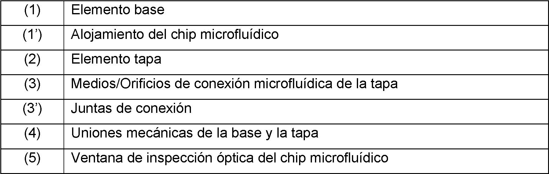
DESCRIPCIÓN DETALLADA DE LA INVENCIÓNDETAILED DESCRIPTION OF THE INVENTION
Diferentes ejemplos de realizaciones preferentes del dispositivo de la invención se muestran en las Figuras 1-4 del presente documento. En dichas figuras, se aprecia cómo el citado dispositivo consta, principalmente, de dos elementos: un elemento base (1) y un elemento tapa (2), que en su conjunto sirven como herramienta para la aplicación de flujo a dispositivos microfluídicos de tipo chip, preferentemente fabricados con base polimérica (comprendiendo, típicamente, polidimetil-siloxano (PDMS)) en un entorno celular concreto. No obstante, la utilización de este material no supone un uso restringido únicamente a este tipo de dispositivos, pudiendo adaptarse sin limitación a otros chips fabricados con diferentes materiales que mantengan unas dimensiones concretas, y que sean susceptibles de monitorización mediante microscopía.Different examples of preferred embodiments of the device of the invention are shown in Figures 1-4 of this document. In these figures, it can be seen how the said device mainly consists of two elements: a base element (1) and a cover element (2), which together serve as a tool for the application of flow to chip-type microfluidic devices. , preferably made with a polymer base (typically comprising polydimethylsiloxane (PDMS)) in a specific cellular environment. However, the use of this material does not imply a restricted use only to this type of device, being able to adapt without limitation to other chips made with different materials that maintain specific dimensions, and that are susceptible to monitoring by microscopy.
El elemento base (1) está fabricado preferentemente a base de un material metálico, y consta de uno o más alojamientos (1’) en los que se dispone el chip microfluídico a visualizar y manipular. Ello permite obtener una plataforma sólida de soporte de dicho dispositivo, asegurando la estabilidad del mismo durante la realización de los experimentos. Asimismo, la posibilidad de incluir más de un alojamiento (1’) en el dispositivo permite la duplicidad simultánea de los ensayos colocados en flujo, con visualización microscópica tridimensional en tiempo real, así como una nula interferencia para su utilización en microscopía (por ejemplo, microscopía confocal). En las Figuras 3 y 4 se muestra una realización preferente de la invención donde la base (1) comprende dos alojamientos (1’) de dispositivos microfluídicos.The base element (1) is preferably made from a metallic material, and consists of one or more housings (1 ') in which the microfluidic chip to be viewed and manipulated is arranged. This allows obtaining a solid support platform for said device, ensuring its stability during the experiments. Likewise, the possibility of including more than one housing (1 ') in the device allows the simultaneous duplication of the tests placed in flow, with real-time three-dimensional microscopic visualization, as well as zero interference for use in microscopy (for example, confocal microscopy). Figures 3 and 4 show a preferred embodiment of the invention where the base (1) comprises two housings (1 ') of microfluidic devices.
El elemento base (1) es preferentemente reutilizable, y puede ser sometido a procesos de esterilización en autoclave, así como a una exposición prolongada en el tiempo a temperaturas del orden de 37 °C durante el desarrollo de los ensayos. Para ello, se seleccionará, preferentemente, el aluminio, ya que es más estable que otros metales, como podría ser el acero inoxidable, cuando se somete a temperaturas de 37°C durante períodos de tiempo prolongados. Opcionalmente, el posterior anodizado del aluminio se puede utilizar para reducir o evitar el deterioro de la base (1) por factores ambientales, tales como la humedad.The base element (1) is preferably reusable, and can be subjected to autoclave sterilization processes, as well as prolonged exposure over time to temperatures of the order of 37 ° C during the development of the tests. For this, aluminum will preferably be selected, since it is more stable than other metals, such as stainless steel, when subjected to temperatures of 37 ° C for long periods of time. Optionally, the subsequent anodized aluminum can be used to reduce or prevent deterioration of the base (1) due to environmental factors, such as humidity.
De este modo, el material metálico empleado para la base (1) presenta un comportamiento óptimo ante variaciones de temperatura, con unas deformaciones despreciables ante estas condiciones de trabajo durante su funcionamiento y uso.In this way, the metallic material used for the base (1) presents an optimal behavior in the face of temperature variations, with negligible deformations under these working conditions during its operation and use.
En cuanto a las dimensiones preferentes del elemento base (1), éstas siguen preferentemente las especificaciones de la norma ANSI/SBS (1-4)-2004, siendo así el dispositivo de la invención compatible con todo tipo de microscopios dotados de un adaptador para microplacas.As for the preferred dimensions of the base element (1), these preferably follow the specifications of the ANSI / SBS (1-4) -2004 standard, thus making the device of the invention compatible with all types of microscopes equipped with an adapter for microplates.
Por su parte, el elemento tapa (2) está fabricado preferentemente con un material plástico a base de resinas fotopolimerizables, aptas para su impresión mediante técnicas de fabricación aditiva (impresión 3D). La selección de estos materiales específicos consigue el doble efecto de: (i) permitir una producción a gran escala de dicha tapa (2), adaptable a cualquier geometría de chips utilizados, y (ii) proporcionar la capacidad de de soportar altas temperaturas de esterilización (superiores a 100°C en tiempos cortos correspondientes a las operaciones de autoclavado), y ser además adaptable a las pequeñas deformaciones que pueda sufrir el material con el paso del tiempo, no afectan ni a la inyección del flujo ni a la visualización microscópica del chip. De este modo, la combinación del material metálico (y especialmente del aluminio) de la base (1) con el material plástico basado en resinas fotopolimerizables de la tapa (2) confieren, en la presente invención, la capacidad de mejorar sustancialmente las soluciones conocidas y superar las limitaciones de las mismas.For its part, the cover element (2) is preferably made of a plastic material based on light-curing resins, suitable for printing using additive manufacturing techniques (3D printing). The selection of these specific materials achieves the double effect of: (i) allowing a large-scale production of said cover (2), adaptable to any chip geometry used, and (ii) provide the ability to withstand high sterilization temperatures (above 100 ° C in short times corresponding to autoclaving operations), and also be adaptable to small deformations that the material may suffer over time, they do not affect either flow injection or microscopic visualization of the chip. Thus, the combination of the metallic material (and especially the aluminum) of the base (1) with the plastic material based on photopolymerizable resins of the cover (2) confer, in the present invention, the ability to substantially improve the known solutions and overcome their limitations.
Así, la combinación de dos tipos distintos de materiales para la fabricación de la invención (metal para la base (1) y fotorresina plástica imprimible en 3D para la tapa (2)) aporta al dispositivo una gran estabilidad en su estado final de montaje (con deformaciones despreciables en un rango de temperaturas entre 35-39°C), y también una gran adaptabilidad al chip microfluídico, debido a la mayor capacidad de deformación del elemento tapa (2).Thus, the combination of two different types of materials for the manufacture of the invention (metal for the base (1) and 3D printable plastic photoresin for the cover (2)) gives the device great stability in its final state of assembly ( with negligible deformations in a temperature range between 35-39 ° C), and also a great adaptability to the microfluidic chip, due to the greater deformation capacity of the cover element (2).
Por otra parte, y según se aprecia en las Figuras 1-4, el elemento tapa (2) presenta unos orificios (3) roscados (por ejemplo, de tipo 10-32 UNF), los cuales permiten realizar las conexiones con los tubos para la aplicación del flujo, de forma rápida y sencilla.On the other hand, and as seen in Figures 1-4, the cover element (2) has threaded holes (3) (for example, type 10-32 UNF), which allow connections to be made with the tubes for the application of the flow, quickly and easily.
El comportamiento elástico del material plástico utilizado facilita, además, el ajuste óptimo de ambos elementos, base (1) y tapa (2). Por otro lado, para garantizar adicionalmente la estanqueidad del dispositivo en su unión con el chip, en la parte interior de la tapa (2) pueden disponerse uno o más rebajes, configurados con una o más juntas (3’) tóricas u “o-rings” integrados en los orificios (3) roscados de la tapa (2), de forma correspondiente a cada uno de los orificios de entrada/salida del chip microfluídico alojado. De este modo, se asegura una correcta conexión microfluídica del dispositivo al citado chip.The elastic behavior of the plastic material used also facilitates the optimal adjustment of both elements, base (1) and cover (2). On the other hand, to additionally guarantee the tightness of the device in its union with the chip, one or more recesses can be arranged on the inside of the cover (2), configured with one or more O-rings (3 ') or “o- rings ”integrated in the threaded holes (3) of the cover (2), corresponding to each of the inlet / outlet holes of the micro-fluid chip housed. In this way, a correct microfluidic connection of the device to said chip is ensured.
Asimismo, exteriormente el dispositivo está conectado, preferentemente, a una pluralidad de tubos de circulación de flujo comprendidos en el circuito microfluídico del que formará parte, típicamente, la invención durante su uso. La conexión entre los tubos y el dispositivo se realiza, preferentemente, mediante un conector rápido roscado a la tapa (2) y conectado al tubo, por el que entrará o saldrá del dispositivo, por ejemplo uniéndose al final de su recorrido a una jeringa, u otros medios similares utilizados para provocar el desplazamiento de flujo en el circuito microfluídico desde o hacia el dispositivo. El diseño propuesto resulta especialmente adecuado para garantizar su estanqueidad, y evitar la aparición de burbujas en el citado circuito.Also, externally the device is preferably connected to a plurality of flow circulation tubes comprised in the microfluidic circuit of which the invention will typically form part during use. The connection between the tubes and the device is preferably carried out by means of a quick connector threaded to the cap (2) and connected to the tube, through which it will enter or exit the device, for example joining a syringe at the end of its travel, or other similar means used to cause displacement of flow in the microfluidic circuit to or from the device. Design proposed is especially suitable to guarantee its tightness, and avoid the appearance of bubbles in the aforementioned circuit.
Por su parte, el acoplamiento entre los dos elementos (1, 2) principales del dispositivo se realiza, preferentemente, mediante uniones mecánicas (4) roscadas tuerca-tornillo, en una pluralidad de puntos del soporte (por ejemplo, seis puntos en las realizaciones mostradas en las Figuras 1-4), garantizando una adecuada fijación y estabilidad del dispositivo. La tapa (2) puede incluir, adicionalmente, un diseño de encaje en el interior de la base (1), presentando por ejemplo una geometría en relieve correspondiente con la del chip microfluídico a alojar, con el objetivo de evitar un mal montaje de éste en el encapsulado, mediante un diseño de tipo Poka-Yoke.For its part, the coupling between the two main elements (1, 2) of the device is preferably carried out by means of mechanical unions (4) threaded nut-screw, in a plurality of points of the support (for example, six points in the embodiments shown in Figures 1-4), guaranteeing an adequate fixation and stability of the device. The cover (2) may additionally include a lace design inside the base (1), presenting, for example, a geometry in relief corresponding to that of the microfluidic chip to be housed, in order to avoid a bad assembly of it in the package, using a Poka-Yoke type design.
Como se ha mencionado, según la descripción proporcionada la invención está orientada para facilitar al usuario el análisis 4D de los efectos del flujo de fluido aplicado a cultivos celulares en 3D, aunque también se puede utilizar sin limitación para el estudio de cultivos bidimensionales. Para facilitar la monitorización del chip a través del dispositivo, la tapa (2) comprende, preferentemente, al menos una ventana (5) de inspección óptica que comunica con el chip microfluídico, y que está dispuesta para facilitar el acceso por parte del sistema de microscopía utilizado para registrar la actividad en el chip durante los ensayos.As mentioned, according to the description provided, the invention is oriented to facilitate the user with 4D analysis of the effects of fluid flow applied to 3D cell cultures, although it can also be used without limitation for the study of two-dimensional cultures. To facilitate monitoring of the chip through the device, the cover (2) preferably comprises at least one optical inspection window (5) that communicates with the microfluidic chip, and which is arranged to facilitate access by the system of Microscopy used to record activity on the chip during assays.
A modo de resumen, se describen de nuevo las ventajas principales de la invención:By way of summary, the main advantages of the invention are described again:
- Combinación de un material metálico en la base y un material plástico en la tapa, para adaptarse a las pequeñas deformaciones que pudiera sufrir el material de la impresora 3D, compensándose gracias a las diferencias de coeficientes de elasticidad de ambos materiales.- Combination of a metallic material in the base and a plastic material in the cover, to adapt to the small deformations that the 3D printer material could suffer, compensating thanks to the differences in elasticity coefficients of both materials.
- Acoplamiento sencillo basado preferentemente en uniones atornilladas, que permite regular en altura y ajustar la tapa (2) a las dimensiones del chip que se aloja en su interior.- Simple coupling preferably based on screwed joints, which allows height adjustment and adjustment of the cover (2) to the dimensions of the chip that is housed inside.
- Capacidad de realizar una multiplicidad de ensayos simultáneos, mediante el uso de una pluralidad de alojamientos de chips en la base (1).- Ability to perform a multiplicity of simultaneous tests, by using a plurality of chip housings in the base (1).
- Versatilidad para adaptar el dispositivo a todo tipo de chips, así como a diferentes tamaños de los mismos por la simplicidad del proceso de fabricación de la invención. A su vez, las dimensiones típicas y adaptables del dispositivo lo hacen compatible con cualquier tipo o marca de microscopio.- Versatility to adapt the device to all types of chips, as well as to different sizes of them due to the simplicity of the manufacturing process of the invention. In turn, the typical and adaptable dimensions of the device make it compatible with any type or brand of microscope.
El dispositivo de la invención se ha aplicado experimentalmente con éxito para la circulación de fluido a cultivos celulares. A lo largo de la exposición a flujo, no se han visto fugas en el montaje y se ha conseguido la difusión de éste a través del gel durante días, manteniéndose su integridad, sin ningún tipo de fugas. Para probar la resistencia a la temperatura de cada uno de los elementos (1, 2) que forman el dispositivo, ambos se han sometido a ciclos de autoclavado, observándose una nula o mínima deformación en la tapa (2) que no afecta al comportamiento global del dispositivo, gracias a la adecuada selección de sus materiales de fabricación. The device of the invention has been successfully applied experimentally for fluid circulation to cell cultures. Throughout the exposure to flow, no leaks have been seen in the assembly and its diffusion has been achieved through the gel for days, maintaining its integrity, without any type of leakage. To test the temperature resistance of each of the elements (1, 2) that make up the device, both have undergone autoclaving cycles, observing no or minimal deformation in the cover (2) that does not affect the overall behavior of the device, thanks to the adequate selection of its manufacturing materials.
Claims (10)


Priority Applications (1)
| Application Number | Priority Date | Filing Date | Title |
|---|---|---|---|
| ES201932084U ES1245110Y (en) | 2017-06-16 | 2017-06-16 | ENCAPSULATION DEVICE SUITABLE FOR MICROFLUID APPLICATIONS |
Applications Claiming Priority (1)
| Application Number | Priority Date | Filing Date | Title |
|---|---|---|---|
| ES201932084U ES1245110Y (en) | 2017-06-16 | 2017-06-16 | ENCAPSULATION DEVICE SUITABLE FOR MICROFLUID APPLICATIONS |
Publications (2)
| Publication Number | Publication Date |
|---|---|
| ES1245110U true ES1245110U (en) | 2020-04-23 |
| ES1245110Y ES1245110Y (en) | 2020-08-21 |
Family
ID=70294655
Family Applications (1)
| Application Number | Title | Priority Date | Filing Date |
|---|---|---|---|
| ES201932084U Expired - Fee Related ES1245110Y (en) | 2017-06-16 | 2017-06-16 | ENCAPSULATION DEVICE SUITABLE FOR MICROFLUID APPLICATIONS |
Country Status (1)
| Country | Link |
|---|---|
| ES (1) | ES1245110Y (en) |
-
2017
- 2017-06-16 ES ES201932084U patent/ES1245110Y/en not_active Expired - Fee Related
Also Published As
| Publication number | Publication date |
|---|---|
| ES1245110Y (en) | 2020-08-21 |
Similar Documents
| Publication | Publication Date | Title |
|---|---|---|
| ES2615512B1 (en) | DEVICE AND MICROFLUIDIC SYSTEM FOR THE STUDY OF CELL CULTURES | |
| JP7502054B2 (en) | Slide Chamber | |
| ES2813939T3 (en) | Reaction system | |
| US10119112B2 (en) | Multi-reactor unit for dynamic cell culture | |
| CN104837560B (en) | Cartridge and apparatus for preparing a biological sample | |
| JP2013532488A (en) | Pressurizable cartridge for polymerase chain reaction | |
| ES2983869T3 (en) | Procedure for enriching gas and simultaneously displacing a fluid, and system for controlling the cellular environment on a corresponding multi-well cell culture plate | |
| CN106807468A (en) | Micro-fluidic chip clamp and droplet preparation system | |
| US6783928B2 (en) | Microstructures for cell proliferation assays and semen analysis | |
| CN104099247A (en) | Pressurized cell culture system and method based on micro-fluidic chip | |
| BR112015027553B1 (en) | assembly to prepare a specimen to determine the presence of at least one species of microorganism in the specimen and method for preparing a specimen to determine the presence of at least one species of microorganism in the specimen | |
| JP6959929B2 (en) | Disposable connecting device | |
| ES2869703T3 (en) | Method for extracting nucleic acid and extraction cassette thereof. | |
| KR101706153B1 (en) | Microfluidic chip-based cell cultivation system | |
| US10014154B2 (en) | Method for enabling modular part replacement within an electron microscope sample holder | |
| CN106164662B (en) | Electrodes, Combination Electrodes, Liquid Analyzers | |
| ES2930540T3 (en) | bioprocessing device | |
| ES1245110U (en) | CAPSULE DEVICE SUITABLE FOR MICROFLUIDIC APPLICATIONS (Machine-translation by Google Translate, not legally binding) | |
| ES2365282B1 (en) | MICROCAMARA AND MONITORIZABLE CELLULAR CULTURE DEVICE BY NUCLEAR MAGNETIC RESONANCE | |
| ES3047833T3 (en) | Rapid cell culture monitoring device including island structure | |
| US12332160B2 (en) | Apparatus, system, and method for testing biological samples | |
| US12553017B2 (en) | Apparatus for microscopic biolocigal organism observation | |
| TWI909490B (en) | Organ chip assembly for simulating physiological barrier environment, microfluidic apparatus and method for simulating a physiological barrier environment | |
| CN219215992U (en) | A kind of disposable biotechnology bag | |
| CN105349423B (en) | A kind of vascular fluid platform application method of separate chamber |
Legal Events
| Date | Code | Title | Description |
|---|---|---|---|
| CA1K | Utility model application published |
Ref document number: 1245110 Country of ref document: ES Kind code of ref document: U Effective date: 20200423 |
|
| FG1K | Utility model granted |
Ref document number: 1245110 Country of ref document: ES Kind code of ref document: Y Effective date: 20200817 |
|
| FD1K | Utility model lapsed |
Effective date: 20240401 |