ES2803244T3 - Inkjet Liquid Ink and Printing Procedure - Google Patents
Inkjet Liquid Ink and Printing Procedure Download PDFInfo
- Publication number
- ES2803244T3 ES2803244T3 ES10755134T ES10755134T ES2803244T3 ES 2803244 T3 ES2803244 T3 ES 2803244T3 ES 10755134 T ES10755134 T ES 10755134T ES 10755134 T ES10755134 T ES 10755134T ES 2803244 T3 ES2803244 T3 ES 2803244T3
- Authority
- ES
- Spain
- Prior art keywords
- substrate
- ink
- image
- weight
- ink composition
- Prior art date
- Legal status (The legal status is an assumption and is not a legal conclusion. Google has not performed a legal analysis and makes no representation as to the accuracy of the status listed.)
- Active
Links
- 238000000034 method Methods 0.000 title claims abstract description 56
- 239000007788 liquid Substances 0.000 title claims description 29
- 238000007639 printing Methods 0.000 title description 35
- 239000000758 substrate Substances 0.000 claims abstract description 70
- 239000000203 mixture Substances 0.000 claims abstract description 55
- 239000002245 particle Substances 0.000 claims abstract description 40
- 239000003550 marker Substances 0.000 claims abstract description 29
- 239000000463 material Substances 0.000 claims abstract description 24
- 239000002966 varnish Substances 0.000 claims abstract description 20
- 230000005684 electric field Effects 0.000 claims abstract description 14
- 239000003086 colorant Substances 0.000 claims abstract description 9
- 239000012530 fluid Substances 0.000 claims abstract description 9
- 238000000151 deposition Methods 0.000 claims abstract description 8
- 239000011248 coating agent Substances 0.000 claims abstract description 7
- 238000000576 coating method Methods 0.000 claims abstract description 7
- 239000012141 concentrate Substances 0.000 claims abstract description 6
- 230000002745 absorbent Effects 0.000 claims description 12
- 239000002250 absorbent Substances 0.000 claims description 12
- 239000000945 filler Substances 0.000 claims description 10
- 239000011230 binding agent Substances 0.000 claims description 9
- 239000002270 dispersing agent Substances 0.000 claims description 9
- 239000003795 chemical substances by application Substances 0.000 claims description 4
- 150000001338 aliphatic hydrocarbons Chemical class 0.000 claims description 3
- 239000004067 bulking agent Substances 0.000 claims 1
- 239000000976 ink Substances 0.000 description 78
- 239000000049 pigment Substances 0.000 description 22
- 230000008569 process Effects 0.000 description 19
- 238000000926 separation method Methods 0.000 description 12
- 229920000642 polymer Polymers 0.000 description 8
- 239000000126 substance Substances 0.000 description 8
- 230000008901 benefit Effects 0.000 description 7
- XLYOFNOQVPJJNP-UHFFFAOYSA-N water Substances O XLYOFNOQVPJJNP-UHFFFAOYSA-N 0.000 description 6
- 238000005349 anion exchange Methods 0.000 description 5
- 238000010586 diagram Methods 0.000 description 5
- 229910052751 metal Inorganic materials 0.000 description 5
- 239000002184 metal Substances 0.000 description 5
- 239000011347 resin Substances 0.000 description 5
- 229920005989 resin Polymers 0.000 description 5
- 239000007787 solid Substances 0.000 description 5
- 239000002904 solvent Substances 0.000 description 5
- 239000004020 conductor Substances 0.000 description 4
- 238000001723 curing Methods 0.000 description 4
- 238000005516 engineering process Methods 0.000 description 4
- 230000010287 polarization Effects 0.000 description 4
- 229920002799 BoPET Polymers 0.000 description 3
- QCWXUUIWCKQGHC-UHFFFAOYSA-N Zirconium Chemical compound [Zr] QCWXUUIWCKQGHC-UHFFFAOYSA-N 0.000 description 3
- 238000010521 absorption reaction Methods 0.000 description 3
- -1 aromatic tertiary amine Chemical class 0.000 description 3
- 229920001577 copolymer Polymers 0.000 description 3
- 238000003384 imaging method Methods 0.000 description 3
- 230000005499 meniscus Effects 0.000 description 3
- VLKZOEOYAKHREP-UHFFFAOYSA-N n-Hexane Chemical compound CCCCCC VLKZOEOYAKHREP-UHFFFAOYSA-N 0.000 description 3
- 238000004806 packaging method and process Methods 0.000 description 3
- 230000001681 protective effect Effects 0.000 description 3
- 230000000007 visual effect Effects 0.000 description 3
- 229910052726 zirconium Inorganic materials 0.000 description 3
- CNPVJWYWYZMPDS-UHFFFAOYSA-N 2-methyldecane Chemical compound CCCCCCCCC(C)C CNPVJWYWYZMPDS-UHFFFAOYSA-N 0.000 description 2
- SGVYKUFIHHTIFL-UHFFFAOYSA-N 2-methylnonane Chemical compound CCCCCCCC(C)C SGVYKUFIHHTIFL-UHFFFAOYSA-N 0.000 description 2
- 239000004925 Acrylic resin Substances 0.000 description 2
- 229920000178 Acrylic resin Polymers 0.000 description 2
- IJGRMHOSHXDMSA-UHFFFAOYSA-N Atomic nitrogen Chemical compound N#N IJGRMHOSHXDMSA-UHFFFAOYSA-N 0.000 description 2
- 238000003848 UV Light-Curing Methods 0.000 description 2
- 238000005299 abrasion Methods 0.000 description 2
- 150000001335 aliphatic alkanes Chemical class 0.000 description 2
- 150000004982 aromatic amines Chemical class 0.000 description 2
- 230000015556 catabolic process Effects 0.000 description 2
- 239000008199 coating composition Substances 0.000 description 2
- 238000004040 coloring Methods 0.000 description 2
- 238000005034 decoration Methods 0.000 description 2
- 238000006731 degradation reaction Methods 0.000 description 2
- 150000002148 esters Chemical class 0.000 description 2
- 238000009472 formulation Methods 0.000 description 2
- 238000010438 heat treatment Methods 0.000 description 2
- 239000003999 initiator Substances 0.000 description 2
- 238000007641 inkjet printing Methods 0.000 description 2
- 229910052757 nitrogen Inorganic materials 0.000 description 2
- 239000005022 packaging material Substances 0.000 description 2
- 239000011236 particulate material Substances 0.000 description 2
- 229920000139 polyethylene terephthalate Polymers 0.000 description 2
- 239000005020 polyethylene terephthalate Substances 0.000 description 2
- 230000009467 reduction Effects 0.000 description 2
- 229920002554 vinyl polymer Polymers 0.000 description 2
- SMZOUWXMTYCWNB-UHFFFAOYSA-N 2-(2-methoxy-5-methylphenyl)ethanamine Chemical compound COC1=CC=C(C)C=C1CCN SMZOUWXMTYCWNB-UHFFFAOYSA-N 0.000 description 1
- NIXOWILDQLNWCW-UHFFFAOYSA-N 2-Propenoic acid Natural products OC(=O)C=C NIXOWILDQLNWCW-UHFFFAOYSA-N 0.000 description 1
- XDTMQSROBMDMFD-UHFFFAOYSA-N Cyclohexane Chemical compound C1CCCCC1 XDTMQSROBMDMFD-UHFFFAOYSA-N 0.000 description 1
- IMROMDMJAWUWLK-UHFFFAOYSA-N Ethenol Chemical compound OC=C IMROMDMJAWUWLK-UHFFFAOYSA-N 0.000 description 1
- XTXRWKRVRITETP-UHFFFAOYSA-N Vinyl acetate Chemical compound CC(=O)OC=C XTXRWKRVRITETP-UHFFFAOYSA-N 0.000 description 1
- BZHJMEDXRYGGRV-UHFFFAOYSA-N Vinyl chloride Chemical compound ClC=C BZHJMEDXRYGGRV-UHFFFAOYSA-N 0.000 description 1
- 230000002730 additional effect Effects 0.000 description 1
- 125000001931 aliphatic group Chemical group 0.000 description 1
- 125000000217 alkyl group Chemical group 0.000 description 1
- 238000007774 anilox coating Methods 0.000 description 1
- 125000000129 anionic group Chemical group 0.000 description 1
- 230000000712 assembly Effects 0.000 description 1
- 238000000429 assembly Methods 0.000 description 1
- 239000011324 bead Substances 0.000 description 1
- 235000013361 beverage Nutrition 0.000 description 1
- 230000015572 biosynthetic process Effects 0.000 description 1
- 230000000740 bleeding effect Effects 0.000 description 1
- 150000001875 compounds Chemical class 0.000 description 1
- 230000008021 deposition Effects 0.000 description 1
- 238000005137 deposition process Methods 0.000 description 1
- ZBCBWPMODOFKDW-UHFFFAOYSA-N diethanolamine Chemical compound OCCNCCO ZBCBWPMODOFKDW-UHFFFAOYSA-N 0.000 description 1
- 239000006185 dispersion Substances 0.000 description 1
- 239000000975 dye Substances 0.000 description 1
- 238000001227 electron beam curing Methods 0.000 description 1
- 238000001962 electrophoresis Methods 0.000 description 1
- 239000003822 epoxy resin Substances 0.000 description 1
- 230000008020 evaporation Effects 0.000 description 1
- 238000001704 evaporation Methods 0.000 description 1
- LNEPOXFFQSENCJ-UHFFFAOYSA-N haloperidol Chemical compound C1CC(O)(C=2C=CC(Cl)=CC=2)CCN1CCCC(=O)C1=CC=C(F)C=C1 LNEPOXFFQSENCJ-UHFFFAOYSA-N 0.000 description 1
- 125000000623 heterocyclic group Chemical group 0.000 description 1
- 239000001257 hydrogen Substances 0.000 description 1
- 229910052739 hydrogen Inorganic materials 0.000 description 1
- 239000004615 ingredient Substances 0.000 description 1
- 239000004922 lacquer Substances 0.000 description 1
- 125000005647 linker group Chemical group 0.000 description 1
- 231100000053 low toxicity Toxicity 0.000 description 1
- 238000004519 manufacturing process Methods 0.000 description 1
- 229920003145 methacrylic acid copolymer Polymers 0.000 description 1
- 239000000178 monomer Substances 0.000 description 1
- 125000004433 nitrogen atom Chemical group N* 0.000 description 1
- 230000003287 optical effect Effects 0.000 description 1
- 238000012858 packaging process Methods 0.000 description 1
- 239000001042 pigment based ink Substances 0.000 description 1
- 239000004033 plastic Substances 0.000 description 1
- 229920003023 plastic Polymers 0.000 description 1
- 239000002798 polar solvent Substances 0.000 description 1
- 229920013639 polyalphaolefin Polymers 0.000 description 1
- 229920000647 polyepoxide Polymers 0.000 description 1
- 239000002952 polymeric resin Substances 0.000 description 1
- 238000011417 postcuring Methods 0.000 description 1
- 239000000843 powder Substances 0.000 description 1
- 230000005855 radiation Effects 0.000 description 1
- 230000004044 response Effects 0.000 description 1
- 150000003839 salts Chemical class 0.000 description 1
- 238000007650 screen-printing Methods 0.000 description 1
- 239000000344 soap Substances 0.000 description 1
- 238000003892 spreading Methods 0.000 description 1
- 230000007480 spreading Effects 0.000 description 1
- 229920001909 styrene-acrylic polymer Polymers 0.000 description 1
- 239000004094 surface-active agent Substances 0.000 description 1
- 229920001059 synthetic polymer Polymers 0.000 description 1
- 229920003002 synthetic resin Polymers 0.000 description 1
- 239000000057 synthetic resin Substances 0.000 description 1
- 238000001029 thermal curing Methods 0.000 description 1
- 125000000391 vinyl group Chemical group [H]C([*])=C([H])[H] 0.000 description 1
- 239000002699 waste material Substances 0.000 description 1
Classifications
-
- B—PERFORMING OPERATIONS; TRANSPORTING
- B41—PRINTING; LINING MACHINES; TYPEWRITERS; STAMPS
- B41J—TYPEWRITERS; SELECTIVE PRINTING MECHANISMS, i.e. MECHANISMS PRINTING OTHERWISE THAN FROM A FORME; CORRECTION OF TYPOGRAPHICAL ERRORS
- B41J2/00—Typewriters or selective printing mechanisms characterised by the printing or marking process for which they are designed
- B41J2/005—Typewriters or selective printing mechanisms characterised by the printing or marking process for which they are designed characterised by bringing liquid or particles selectively into contact with a printing material
- B41J2/01—Ink jet
- B41J2/015—Ink jet characterised by the jet generation process
- B41J2/04—Ink jet characterised by the jet generation process generating single droplets or particles on demand
- B41J2/06—Ink jet characterised by the jet generation process generating single droplets or particles on demand by electric or magnetic field
-
- C—CHEMISTRY; METALLURGY
- C09—DYES; PAINTS; POLISHES; NATURAL RESINS; ADHESIVES; COMPOSITIONS NOT OTHERWISE PROVIDED FOR; APPLICATIONS OF MATERIALS NOT OTHERWISE PROVIDED FOR
- C09D—COATING COMPOSITIONS, e.g. PAINTS, VARNISHES OR LACQUERS; FILLING PASTES; CHEMICAL PAINT OR INK REMOVERS; INKS; CORRECTING FLUIDS; WOODSTAINS; PASTES OR SOLIDS FOR COLOURING OR PRINTING; USE OF MATERIALS THEREFOR
- C09D11/00—Inks
- C09D11/30—Inkjet printing inks
-
- B—PERFORMING OPERATIONS; TRANSPORTING
- B41—PRINTING; LINING MACHINES; TYPEWRITERS; STAMPS
- B41J—TYPEWRITERS; SELECTIVE PRINTING MECHANISMS, i.e. MECHANISMS PRINTING OTHERWISE THAN FROM A FORME; CORRECTION OF TYPOGRAPHICAL ERRORS
- B41J2/00—Typewriters or selective printing mechanisms characterised by the printing or marking process for which they are designed
- B41J2/005—Typewriters or selective printing mechanisms characterised by the printing or marking process for which they are designed characterised by bringing liquid or particles selectively into contact with a printing material
- B41J2/01—Ink jet
- B41J2/015—Ink jet characterised by the jet generation process
- B41J2/04—Ink jet characterised by the jet generation process generating single droplets or particles on demand
- B41J2/06—Ink jet characterised by the jet generation process generating single droplets or particles on demand by electric or magnetic field
- B41J2/065—Ink jet characterised by the jet generation process generating single droplets or particles on demand by electric or magnetic field involving the preliminary making of ink protuberances
-
- B—PERFORMING OPERATIONS; TRANSPORTING
- B41—PRINTING; LINING MACHINES; TYPEWRITERS; STAMPS
- B41M—PRINTING, DUPLICATING, MARKING, OR COPYING PROCESSES; COLOUR PRINTING
- B41M1/00—Inking and printing with a printer's forme
- B41M1/26—Printing on other surfaces than ordinary paper
-
- B—PERFORMING OPERATIONS; TRANSPORTING
- B41—PRINTING; LINING MACHINES; TYPEWRITERS; STAMPS
- B41M—PRINTING, DUPLICATING, MARKING, OR COPYING PROCESSES; COLOUR PRINTING
- B41M1/00—Inking and printing with a printer's forme
- B41M1/26—Printing on other surfaces than ordinary paper
- B41M1/30—Printing on other surfaces than ordinary paper on organic plastics, horn or similar materials
- B41M1/305—Printing on other surfaces than ordinary paper on organic plastics, horn or similar materials using mechanical, physical or chemical means, e.g. corona discharge, etching or organic solvents, to improve ink retention
-
- C—CHEMISTRY; METALLURGY
- C09—DYES; PAINTS; POLISHES; NATURAL RESINS; ADHESIVES; COMPOSITIONS NOT OTHERWISE PROVIDED FOR; APPLICATIONS OF MATERIALS NOT OTHERWISE PROVIDED FOR
- C09D—COATING COMPOSITIONS, e.g. PAINTS, VARNISHES OR LACQUERS; FILLING PASTES; CHEMICAL PAINT OR INK REMOVERS; INKS; CORRECTING FLUIDS; WOODSTAINS; PASTES OR SOLIDS FOR COLOURING OR PRINTING; USE OF MATERIALS THEREFOR
- C09D11/00—Inks
- C09D11/30—Inkjet printing inks
- C09D11/32—Inkjet printing inks characterised by colouring agents
- C09D11/322—Pigment inks
-
- C—CHEMISTRY; METALLURGY
- C09—DYES; PAINTS; POLISHES; NATURAL RESINS; ADHESIVES; COMPOSITIONS NOT OTHERWISE PROVIDED FOR; APPLICATIONS OF MATERIALS NOT OTHERWISE PROVIDED FOR
- C09D—COATING COMPOSITIONS, e.g. PAINTS, VARNISHES OR LACQUERS; FILLING PASTES; CHEMICAL PAINT OR INK REMOVERS; INKS; CORRECTING FLUIDS; WOODSTAINS; PASTES OR SOLIDS FOR COLOURING OR PRINTING; USE OF MATERIALS THEREFOR
- C09D11/00—Inks
- C09D11/30—Inkjet printing inks
- C09D11/40—Ink-sets specially adapted for multi-colour inkjet printing
-
- B—PERFORMING OPERATIONS; TRANSPORTING
- B41—PRINTING; LINING MACHINES; TYPEWRITERS; STAMPS
- B41J—TYPEWRITERS; SELECTIVE PRINTING MECHANISMS, i.e. MECHANISMS PRINTING OTHERWISE THAN FROM A FORME; CORRECTION OF TYPOGRAPHICAL ERRORS
- B41J2/00—Typewriters or selective printing mechanisms characterised by the printing or marking process for which they are designed
- B41J2/005—Typewriters or selective printing mechanisms characterised by the printing or marking process for which they are designed characterised by bringing liquid or particles selectively into contact with a printing material
- B41J2/01—Ink jet
- B41J2/015—Ink jet characterised by the jet generation process
- B41J2/04—Ink jet characterised by the jet generation process generating single droplets or particles on demand
- B41J2/06—Ink jet characterised by the jet generation process generating single droplets or particles on demand by electric or magnetic field
- B41J2002/062—Ink jet characterised by the jet generation process generating single droplets or particles on demand by electric or magnetic field by using a divided counter electrode opposite to ejection openings of an electrostatic printhead, e.g. for controlling the flying direction of ejected toner particles by providing the divided parts of the counter electrode with different potentials
Landscapes
- Chemical & Material Sciences (AREA)
- Engineering & Computer Science (AREA)
- Life Sciences & Earth Sciences (AREA)
- Materials Engineering (AREA)
- Wood Science & Technology (AREA)
- Organic Chemistry (AREA)
- Physics & Mathematics (AREA)
- Plasma & Fusion (AREA)
- Ink Jet Recording Methods And Recording Media Thereof (AREA)
- Inks, Pencil-Leads, Or Crayons (AREA)
- Ink Jet (AREA)
- Particle Formation And Scattering Control In Inkjet Printers (AREA)
- Application Of Or Painting With Fluid Materials (AREA)
Abstract
Un procedimiento para formar una imagen en un sustrato, que comprende depositar composiciones de tinta de al menos dos colores sobre el sustrato para formar la imagen, y fijar la imagen al sustrato, en donde la tinta se deposita usando un cabezal de impresión electrostático, que expulsa partículas marcadoras cargables dispersadas en un fluido portador usando un campo eléctrico aplicado para concentrar primero y luego expulsar las partículas marcadoras, y en donde todas las composiciones de tinta se depositan sobre el sustrato antes de que se fije la imagen; en donde la fijación es recubriendo las composiciones de tinta con un barniz, y luego curando el barniz, o recubriendo previamente la superficie del sustrato con un material de capa base sin curar o parcialmente curado antes de que se depositen todas las composiciones de tinta, y luego fijar las composiciones de tinta curando la capa base después de que se hayan depositado todas las composiciones de tinta.A method of forming an image on a substrate, comprising depositing ink compositions of at least two colors on the substrate to form the image, and fixing the image to the substrate, wherein the ink is deposited using an electrostatic print head, which ejects chargeable marker particles dispersed in a carrier fluid using an applied electric field to first concentrate and then eject the marker particles, and wherein all ink compositions are deposited on the substrate before the image is fixed; wherein the fixation is by coating the ink compositions with a varnish, and then curing the varnish, or by pre-coating the substrate surface with an uncured or partially cured basecoat material before all of the ink compositions are deposited, and then setting the ink compositions by curing the base coat after all the ink compositions have been deposited.
Description
DESCRIPCIÓNDESCRIPTION
Procedimiento de impresión y tinta líquida de chorro de tintaInkjet Liquid Ink and Printing Procedure
Campo de la invenciónField of the invention
La presente invención se refiere a procedimientos de decoración y fijación de imágenes, y tintas para su uso.The present invention relates to image fixing and decoration methods, and inks for their use.
Antecedentes de la invenciónBackground of the invention
Las técnicas de impresión en general se dividen en dos categorías. La primera es la técnica tradicional “analógica” como offset, huecograbado, flexografía o serigrafía. En estas técnicas, se forma una impresión permanente de la imagen a imprimir en una placa de impresión, tambor o pantalla por medios mecánicos o litográficos, a los que se aplica tinta. La imagen se transfiere luego al material a imprimir. En la impresión en color, este proceso se repite varias veces usando una placa, tambor o pantalla diferente y un color de tinta diferente para establecer cada separación de color de la imagen;Printing techniques generally fall into two categories. The first is the traditional “analog” technique such as offset, gravure, flexo or screen printing. In these techniques, a permanent impression of the image to be printed is formed on a printing plate, drum or screen by mechanical or lithographic means, to which ink is applied. The image is then transferred to the material to be printed. In color printing, this process is repeated multiple times using a different plate, drum, or screen and a different ink color to establish each color separation of the image;
La segunda técnica de impresión es la impresión “digital”, mediante la cual una imagen almacenada en la memoria de la computadora se forma directamente sobre el material a imprimir mediante un sistema controlado electrónicamente, sin la necesidad de “herramientas” permanentes. Ejemplos de procedimientos de impresión digital son la electrofotografía de polvo seco, la electrofotografía de tóner líquido, el chorro de tinta continuo (CIJ), el chorro de tinta térmica (TIJ) y el chorro de tinta piezoeléctrico de gota a demanda (DOD).The second printing technique is "digital" printing, whereby an image stored in computer memory is formed directly on the material to be printed by an electronically controlled system, without the need for permanent "tools". Examples of digital printing methods are dry powder electrophotography, liquid toner electrophotography, continuous inkjet (CIJ), thermal inkjet (TIJ), and piezoelectric drop-on-demand (DOD) inkjet.
En todos los casos, la impresión de imágenes en color implica la aplicación secuencial de al menos dos separaciones de color.In all cases, printing color images involves the sequential application of at least two color separations.
La impresión de materiales de embalaje es una parte importante del mercado global de impresión, y la gran mayoría de ésta utiliza técnicas analógicas tradicionales. Sin embargo, existe un fuerte deseo dentro de la industria por los beneficios que ofrece la impresión digital, tales como tiradas económicas, respuesta rápida a las demandas del mercado, personalización y personalización asequibles, reducción de desperdicio y reducción de inventario.Packaging material printing is an important part of the global printing market, and the vast majority of it uses traditional analog techniques. However, there is a strong desire within the industry for the benefits that digital printing offers, such as economical runs, quick response to market demands, affordable personalization and personalization, waste reduction and inventory reduction.
Muchos materiales de embalaje no son absorbentes, normalmente tienen una superficie externa de metal, plástico o barniz. Con el fin de imprimir sobre estos materiales, los procesos de impresión existentes necesitan secar o fijar cada separación de color en el sustrato antes de colocar la separación de color posterior, para evitar manchas y degradación de la imagen; En el caso de los métodos analógicos tradicionales, esto sería el resultado del contacto físico del equipo que imprime los colores posteriores, mientras que en el caso de los métodos sin contacto como la inyección de tinta, la degradación surge del flujo de tinta sobre el sustrato no absorbente.Many packaging materials are non-absorbent, usually having a metal, plastic or varnish outer surface. In order to print on these materials, existing printing processes need to dry or fix each color separation on the substrate before placing the subsequent color separation, to avoid smudging and image degradation; In the case of traditional analog methods, this would be the result of physical contact of the equipment that prints the subsequent colors, while in the case of non-contact methods such as inkjet, degradation arises from the flow of ink on the substrate non absorbent.
La necesidad de secar o fijar cada separación de color antes de colocar el color posterior agrega complejidad al sistema de impresión general. También puede conducir a que el resultado final caiga fuera de los requisitos del cliente, ya sea porque el método de fijación es incapaz de proporcionar los niveles de adhesión requeridos (como es el caso de la formación de imágenes electrofotográficas curadas térmicamente) o porque los productos químicos utilizados para la fijación no son compatibles con los requisitos de seguridad alimentaria de los clientes finales (como es el caso de la inyección de tinta curada con UV).The need to dry or fix each color separation before placing the subsequent color adds complexity to the overall printing system. It can also lead to the end result falling outside the customer's requirements, either because the fixing method is unable to provide the required levels of adhesion (as is the case with thermally cured electrophotographic imaging) or because the products Chemicals used for fixation are not compatible with end customer food safety requirements (such as UV-cured inkjet).
Las impresoras CIJ y TIJ usan tintas a base de agua o solventes. Estos procedimientos no son capaces de crear imágenes de alta calidad en sustratos no absorbentes, porque la tinta no es viscosa y es capaz de hacer fluir el sustrato. Además, las tintas de color utilizadas en estas pequeñas impresoras de chorro de boquilla se basan en colorantes solubles, ya que las tintas a base de pigmento insoluble pueden causar problemas con el bloqueo de la boquilla. Por lo tanto, se excluyen las ventajas de las formulaciones de pigmentos, a saber, mejor agua, calor y solidez a la luz.CIJ and TIJ printers use water-based or solvent-based inks. These procedures are not capable of creating high quality images on non-absorbent substrates, because the ink is not viscous and is able to flow the substrate. Also, the color inks used in these small nozzle jet printers are based on soluble dyes, as insoluble pigment-based inks can cause problems with nozzle blockage. Therefore, the advantages of pigment formulations, namely better water, heat and light fastness are excluded.
El documento WO93/11866 describe una tecnología de impresión por chorro de tinta, en donde se producen gotitas de tamaño variable que contienen una alta concentración de material en partículas. Las ventajas específicas transmitidas por este proceso incluyen la capacidad de formar gotitas más pequeñas que un picolitro al tiempo que se siguen usando pigmentos como material colorante. Como el tamaño de las gotitas está controlado principalmente por la forma de onda de voltaje aplicada a un punto de expulsión, no están limitadas por el tamaño de una boquilla de chorro de tinta. Además, el material colorante se concentra significativamente en las gotitas expulsadas. Por lo tanto, se pueden producir imágenes de alta resolución y alta densidad basadas en pigmentos resistentes a la luz y al agua. WO93 / 11866 describes an ink jet printing technology, where droplets of varying size are produced containing a high concentration of particulate material. Specific advantages conveyed by this process include the ability to form droplets smaller than one picoliter while still using pigments as the coloring material. Since the size of the droplets is mainly controlled by the voltage waveform applied to an ejection point, they are not limited by the size of an ink jet nozzle. Furthermore, the coloring material is significantly concentrated in the expelled droplets. Therefore, high-resolution, high-density images based on light and water resistant pigments can be produced.
El documento WO95/01404 describe tintas de chorro de tinta adecuadas para su uso en el proceso descrito en el documento WO93/11866. Todas las composiciones de tinta descritas en el mismo contienen un aglutinante, tal como una resina sintética.WO95 / 01404 describes inkjet inks suitable for use in the process described in WO93 / 11866. All of the ink compositions described therein contain a binder, such as a synthetic resin.
El documento US4165399 describe composiciones de tinta sin aglomerante, adecuadas para su uso en operaciones de chorro de tinta. Sin embargo, esta composición de tinta solo es adecuada para su uso en superficies de resina polimérica sintética (en la que puede penetrar la composición de tinta). No es adecuada para su uso en superficies no absorbentes. Todas las composiciones de tinta descritas en el mismo contienen entre 0,5 y 5,0 por ciento en peso de un colorante.US4165399 describes binder-free ink compositions suitable for use in inkjet operations. However, this ink composition is only suitable for use on synthetic polymer resin surfaces (into which the ink composition can penetrate). Not suitable for use on surfaces not absorbents. All of the ink compositions described therein contain between 0.5 and 5.0 percent by weight of a colorant.
El documento US 2007/120923 A1 describe composiciones de revestimiento que incluyen resinas formadoras de película y líquidos orgánicos. Las composiciones de la capa superior se incluyen en conjuntos de tintas que también incluyen composiciones de tinta a base de aceite. También describe métodos para la impresión por chorro de tinta usando composiciones de tinta a base de aceite y composiciones de revestimiento.US 2007/120923 A1 describes coating compositions including film-forming resins and organic liquids. Top coat compositions are included in ink sets that also include oil-based ink compositions. It also describes methods for inkjet printing using oil-based ink compositions and coating compositions.
El documento EP 2017016 A1 describe una película de recubrimiento conductora formada sobre un sustrato poniendo en contacto un material conductor cubierto con un material protector con un material que tiene capacidad de intercambio aniónico, a través de un procedimiento en el que se forma una capa de intercambio aniónico que contiene un material que tiene capacidad de intercambio aniónico sobre un sustrato y luego se forma una capa que contiene un material conductor cubierto con un material protector sobre la capa de intercambio aniónico o, alternativamente, a través de un procedimiento en el que se forma una capa que contiene un material conductor cubierto con un material protector sobre un sustrato y luego una capa de intercambio aniónico que contiene un material que tiene capacidad de intercambio aniónico se forma en la capa que contiene un material conductor.Document EP 2017016 A1 describes a conductive coating film formed on a substrate by contacting a conductive material covered with a protective material with a material having anion exchange capacity, through a process in which an exchange layer is formed anionic containing a material having anion exchange capacity on a substrate and then a layer containing a conductive material covered with a protective material is formed on the anion exchange layer or, alternatively, through a process in which it is formed A layer containing a conductive material covered with a protective material on a substrate and then an anion exchange layer containing a material having anion exchange capacity is formed in the layer containing a conductive material.
El documento EP 1927632 A1 describe una composición curable por radiación que comprende un compuesto curable, un fotoiniciador y un co-iniciador, caracterizado por que dicho co-iniciador tiene una estructura según la Fórmula I A-L-B, Fórmula I en donde A representa un resto estructural que comprende una amina terciaria aromática; B representa un resto estructural que comprende al menos una amina terciaria alifática; L representa un grupo de enlace divalente que posiciona el átomo de nitrógeno de la amina aromática del resto estructural A y el nitrógeno de al menos una amina alifática del resto estructural B en una posición 1-3 a 1-23; con la condición de que al menos una amina aromática y al menos una alifática tengan cada una al menos un alfa-hidrógeno.Document EP 1927632 A1 describes a radiation curable composition comprising a curable compound, a photoinitiator and a co-initiator, characterized in that said co-initiator has a structure according to Formula I ALB, Formula I in which A represents a structural moiety comprising an aromatic tertiary amine; B represents a structural moiety comprising at least one aliphatic tertiary amine; L represents a divalent linking group that positions the nitrogen atom of the aromatic amine of structural residue A and the nitrogen of at least one aliphatic amine of structural residue B at a position 1-3 to 1-23; with the proviso that at least one aromatic amine and at least one aliphatic each have at least one alpha-hydrogen.
El documento US 2004/259015 A1 describe un líquido de grabación que incluye un colorante y un líquido portador que incluye al menos una poli-alfa-olefina. El líquido de grabación se puede usar como revelador líquido, tinta de chorro de tinta, tinta de impresión, tinta de marcador, tinta de grabación electrónica o similar. También se describe un método de formación de imágenes, que incluye los pasos de aplicar un líquido de grabación en un miembro portador de líquido para formar una capa del líquido de grabación; y desarrollar una imagen latente electrostática nacida en un miembro portador de imágenes, poniendo en contacto la capa del líquido de grabación con el miembro portador de imágenes para formar una imagen visual en el miembro portador de imágenes.US 2004/259015 A1 describes a recording liquid that includes a colorant and a carrier liquid that includes at least one poly-alpha-olefin. The recording liquid can be used as a liquid developer, ink jet ink, printing ink, marker ink, electronic recording ink or the like. An imaging method is also described, including the steps of applying a recording liquid to a liquid-carrying member to form a layer of the recording liquid; and developing an electrostatic latent image born in an image-bearing member by contacting the layer of the recording liquid with the image-bearing member to form a visual image on the image-bearing member.
El documento US 3542682 describe una composición de tóner líquido de trabajo positivo que comprende en un líquido portador eléctricamente aislante, un pigmento, un jabón metálico y un agente dispersante que comprende un polímero alquilado de un monómero de N-vinilo heterocíclico.US 3542682 describes a positive working liquid toner composition comprising in an electrically insulating carrier liquid, a pigment, a metallic soap, and a dispersing agent comprising an alkylated polymer of a heterocyclic N-vinyl monomer.
Sumario de la invenciónSummary of the invention
La presente invención aborda el problema de simplificar el proceso de impresión, al tiempo que permite que se formen imágenes de alta calidad, particularmente en superficies de impresión no absorbentes. Se ha encontrado que esto se puede lograr mediante el uso de un proceso de impresión electrostática sin contacto.The present invention addresses the problem of simplifying the printing process, while allowing high quality images to be formed, particularly on non-absorbent printing surfaces. It has been found that this can be achieved through the use of a non-contact electrostatic printing process.
Por lo tanto, según un primer aspecto, la presente invención es un procedimiento para formar una imagen en un sustrato, que comprende depositar composiciones de tinta de al menos dos colores sobre el sustrato para formar la imagen, y fijar la imagen en el sustrato, en el que la tinta se deposita utilizando un cabezal de impresión electrostático, que expulsa partículas marcadoras cargables dispersas en un fluido portador utilizando un campo eléctrico aplicado para concentrar primero y luego expulsar las partículas marcadoras, y en donde todas las composiciones de tinta se depositan en el sustrato antes de que se fije la imagen; en el que la fijación es recubriendo las composiciones de tinta con un barniz, y luego curando el barniz, o recubriendo previamente la superficie del sustrato con un material de capa base sin curar o parcialmente curado antes de depositar todas las composiciones de tinta, y luego fijar las composiciones de tinta curando la capa base después de que se hayan depositado todas las composiciones de tinta. Therefore, according to a first aspect, the present invention is a method of forming an image on a substrate, which comprises depositing ink compositions of at least two colors on the substrate to form the image, and fixing the image on the substrate, wherein the ink is deposited using an electrostatic print head, which ejects chargeable marker particles dispersed in a carrier fluid using an applied electric field to first concentrate and then eject the marker particles, and wherein all ink compositions are deposited in the substrate before the image is fixed; wherein the fixation is by coating the ink compositions with a varnish, and then curing the varnish, or by pre-coating the substrate surface with an uncured or partially cured basecoat material prior to depositing all the ink compositions, and then setting the ink compositions by curing the base coat after all the ink compositions have been deposited.
También se ha encontrado que las tintas sin aglutinantes que contienen una alta concentración de pigmento son especialmente útiles en un procedimiento de la invención, ya que permiten una independencia completa de los procedimientos de decoración y fijación.Binderless inks containing a high concentration of pigment have also been found to be especially useful in a process of the invention, as they allow complete independence of the decorating and fixing processes.
Por lo tanto, según un segundo aspecto de la presente invención es una composición de tinta que comprende: Therefore, according to a second aspect of the present invention is an ink composition comprising:
45 - 95% en peso de un líquido portador; en donde el líquido portador es un hidrocarburo alifático aislante;45-95% by weight of a carrier liquid; wherein the carrier liquid is an insulating aliphatic hydrocarbon;
6 - 40% en peso de partículas marcadoras cargables insolubles; y6-40% by weight insoluble chargeable marker particles; Y
0,4 - 10% en peso de un dispersante soluble;0.4-10% by weight of a soluble dispersant;
caracterizado por que la tinta no contiene un aglutinante.characterized in that the ink does not contain a binder.
Según un tercer aspecto, la presente invención comprende una composición de tinta según cualquiera de las reivindicaciones 5 a 8, que consiste en: According to a third aspect, the present invention comprises an ink composition according to any of claims 5 to 8, consisting of:
6 - 40% en peso de partículas marcadoras cargables insolubles;6-40% by weight insoluble chargeable marker particles;
0,4 - 10% en peso de un dispersante soluble;0.4-10% by weight of a soluble dispersant;
hasta 2% en peso de un agente de carga de partículas; yup to 2% by weight of a particulate filler; Y
el resto, líquido portador.the rest, carrier fluid.
Según un cuarto aspecto, la presente invención comprende un procedimiento para formar una imagen en un sustrato, que comprende depositar una composición de tinta como se definió directamente arriba sobre el sustrato, y fijar la composición de tinta sobre el sustrato.According to a fourth aspect, the present invention comprises a method of forming an image on a substrate, which comprises depositing an ink composition as defined directly above on the substrate, and fixing the ink composition on the substrate.
Descripción de los dibujosDescription of the drawings
La figura 1 es una vista lateral que muestra la región de un cabezal de impresión electrostática que puede usarse en un procedimiento de la invención.Figure 1 is a side view showing the region of an electrostatic recording head that can be used in a method of the invention.
La figura 2 es un diagrama esquemático en el plano x-z del cabezal de impresión que se muestra en la figura 1. Figure 2 is a schematic diagram in the x-z plane of the printhead shown in Figure 1.
La figura 3 es un diagrama esquemático en el plano y-z del cabezal de impresión que se muestra en la figura 1. Figure 3 is a schematic diagram in the y-z plane of the printhead shown in Figure 1.
La figura 4 es un diagrama esquemático que muestra un ejemplo del procedimiento de impresión según la presente invención, que ilustra la separación del proceso de deposición de tinta y el proceso de fijación.Fig. 4 is a schematic diagram showing an example of the printing method according to the present invention, illustrating the separation of the ink deposition process and the fixing process.
Descripción de las Realizaciones PreferidasDescription of Preferred Embodiments
Como se usa en el presente documento, una partícula marcadora cargable es un material que cambia el color de la luz que refleja como resultado de la absorción selectiva del color, es decir, un pigmento cargable, que incluye la absorción completa (negro) y ninguna absorción (blanco). La partícula marcadora que es adecuada para usar en la invención es predominantemente insoluble en el líquido portador. Preferiblemente, menos del 1% de las partículas marcadoras son solubles en el líquido portador. Ejemplos de partículas marcadoras adecuadas para usar en la invención son PB15:3 (cian), PR57:1 (magenta), PY12 (amarillo) y SB7 (negro).As used herein, a chargeable marker particle is a material that changes the color of the light it reflects as a result of selective color absorption, i.e., a chargeable pigment, which includes complete absorption (black) and no absorption (white). The marker particle that is suitable for use in the invention is predominantly insoluble in the carrier liquid. Preferably less than 1% of the marker particles are soluble in the carrier liquid. Examples of marker particles suitable for use in the invention are PB15: 3 (cyan), PR57: 1 (magenta), PY12 (yellow) and SB7 (black).
El dispersante es generalmente un material tal como un polímero, un oligómero o un tensioactivo, que se agrega a la composición de tinta en cantidades relativamente pequeñas (menos que la cantidad de pigmento), con el fin de mejorar la dispersión de las partículas marcadoras. El dispersante es predominantemente soluble en el líquido portador. Preferiblemente, es un oligómero o un polímero. Ejemplos de dispersantes incluyen Solsperse S17000 fabricado por Lubrizol y Colorburst 2155.The dispersant is generally a material such as a polymer, an oligomer or a surfactant, which is added to the ink composition in relatively small amounts (less than the amount of pigment), in order to improve the dispersion of the marker particles. The dispersant is predominantly soluble in the carrier liquid. Preferably it is an oligomer or a polymer. Examples of dispersants include Solsperse S17000 manufactured by Lubrizol and Colorburst 2155.
Como se usa en el presente documento, un "agente de carga de partículas" es un agente que puede disociarse en dos o más especies de cargas, una de las cuales se adsorbe preferentemente sobre las partículas marcadoras cargables. Preferiblemente, el agente de carga de partículas es una sal metálica o un disolvente polar. Ejemplos incluyen "Nuxtra Zirconium 6%" de Huls America Inc. y "Octa-Soligen Zirconium 6" de OMG.As used herein, a "particulate filler" is an agent that can dissociate into two or more filler species, one of which is preferentially adsorbed onto the chargeable marker particles. Preferably, the particulate filler is a metal salt or a polar solvent. Examples include "Nuxtra Zirconium 6%" from Huls America Inc. and "Octa-Soligen Zirconium 6" from OMG.
El líquido portador utilizado en las composiciones de tinta de la invención es preferiblemente un líquido que tiene alta resistividad eléctrica, es decir, aislante. Preferiblemente, la resistividad es al menos 109 ohm.cm. Un líquido portador de la invención es preferiblemente orgánico. Es un hidrocarburo alifático, tal como un alcano C1-C20. Más preferiblemente, es un alcano C1-C20 ramificado. Dichos líquidos incluyen Isopar G, hexano, ciclohexano e isodecano. The carrier liquid used in the ink compositions of the invention is preferably a liquid having high electrical resistivity, ie, insulating. Preferably the resistivity is at least 109 ohm.cm. A carrier liquid of the invention is preferably organic. It is an aliphatic hydrocarbon, such as a C 1 -C 20 alkane. More preferably, it is a branched C 1 -C 20 alkane. Such liquids include Isopar G, hexane, cyclohexane, and isodecane.
Las composiciones de la invención se caracterizan por que no contienen un aglutinante, es decir, un agente que puede fijar partículas marcadoras cargables a un sustrato. Un aglutinante es generalmente un polímero o resina, que se agrega a una composición de tinta, generalmente en cantidades comparativamente grandes (mayor que la cantidad de pigmento) para adherir el pigmento al sustrato mediante un proceso de curado posterior. Un aglutinante es generalmente un polímero o una resina que puede reticularse después de la impresión, tales como resinas epoxídicas, resinas acrílicas, tales como polímeros y copolímeros de ácido acrílico y sus ésteres, polímeros y copolímeros de ácido metacrílico y sus ésteres, resinas de vinilo, tales como polímeros y copolímeros que incluyen acetato de vinilo, cloruro de vinilo y alcohol vinílico, y resinas de alquilo.The compositions of the invention are characterized in that they do not contain a binder, that is, an agent that can fix chargeable marker particles to a substrate. A binder is generally a polymer or resin, which is added to an ink composition, generally in comparatively large amounts (greater than the amount of pigment) to adhere the pigment to the substrate through a post-curing process. A binder is generally a polymer or resin that can be cross-linked after printing, such as epoxy resins, acrylic resins, such as polymers and copolymers of acrylic acid and its esters, polymers and copolymers of methacrylic acid and its esters, vinyl resins , such as polymers and copolymers including vinyl acetate, vinyl chloride, and vinyl alcohol, and alkyl resins.
En un aspecto, la presente invención es un procedimiento para formar una imagen en un sustrato, que comprende depositar composiciones de tinta de al menos dos colores sobre el sustrato para formar la imagen, y fijar la imagen en el sustrato, en donde la tinta se deposita usando un cabezal de impresión electrostático, que expulsa partículas marcadoras cargables dispersas en un fluido portador mediante el uso de un campo eléctrico aplicado para concentrar primero y luego expulsar las partículas marcadoras, y en el que todas las composiciones de tinta se depositan en el sustrato antes de que se fije la imagen.In one aspect, the present invention is a method of forming an image on a substrate, which comprises depositing ink compositions of at least two colors on the substrate to form the image, and fixing the image on the substrate, wherein the ink is deposits using an electrostatic print head, which ejects chargeable marker particles dispersed in a carrier fluid by using an applied electric field to first concentrate and then eject the marker particles, and in which all ink compositions are deposited on the substrate before the image is fixed.
Preferiblemente, cada composición de tinta comprende al menos 6% en peso de partículas marcadoras cargables. Más preferiblemente, comprende del 6% al 40% en peso de partículas marcadoras. Más preferiblemente, comprende 6% a 25% u 8% a 25% en peso de partículas marcadoras. Preferiblemente, cada composición de tinta no contiene un agente que pueda fijar las partículas marcadoras cargables al sustrato (un aglutinante). Preferiblemente, la composición de tinta comprende un agente de carga de partículas.Preferably, each ink composition comprises at least 6% by weight of chargeable marker particles. More preferably, it comprises 6% to 40% by weight of marker particles. More preferably, it comprises 6% to 25% or 8% to 25% by weight of marker particles. Preferably, each ink composition does not contain a agent that can bind chargeable marker particles to the substrate (a binder). Preferably, the ink composition comprises a particulate filler.
Un procedimiento de la invención permite el depósito de cantidades muy pequeñas de pigmento (partículas cargables). Esto da como resultado una capa de pigmento concentrada muy delgada y, por lo tanto, es posible establecer las sucesivas separaciones de color sin fijar explícitamente cada separación al sustrato. La deposición concentrada de pigmento asegura que se evite el sangrado y las manchas de las tintas. Cualquier líquido portador residual en la imagen se extrae para dejar una imagen que consiste en una capa delgada y porosa de pigmento sobre el sustrato. A process of the invention allows the deposit of very small amounts of pigment (chargeable particles). This results in a very thin concentrated pigment layer and therefore it is possible to establish successive color separations without explicitly fixing each separation to the substrate. Concentrated pigment deposition ensures that ink bleeding and smearing is avoided. Any residual carrier liquid in the image is removed to leave an image consisting of a thin, porous layer of pigment on the substrate.
Impresoras electrostáticas adecuadas para su uso en la invención expulsan partículas sólidas cargadas dispersas en un fluido portador aislante, químicamente inerte, utilizando un campo eléctrico aplicado para concentrar primero y luego expulsar las partículas sólidas. La concentración ocurre porque el campo eléctrico aplicado causa electroforesis y las partículas cargadas se mueven en el campo eléctrico hacia el sustrato hasta que encuentran la superficie de la tinta. La eyección ocurre cuando el campo eléctrico aplicado crea una fuerza electroforética que es lo suficientemente grande como para superar la tensión superficial. El campo eléctrico se genera creando una diferencia de potencial entre la ubicación de eyección y el sustrato; esto se logra aplicando tensiones a los electrodos en y/o alrededor de la ubicación de eyección.Electrostatic printers suitable for use in the invention eject charged solid particles dispersed in an insulating, chemically inert carrier fluid using an applied electric field to first concentrate and then expel the solid particles. Concentration occurs because the applied electric field causes electrophoresis and the charged particles move in the electric field towards the substrate until they meet the surface of the ink. Ejection occurs when the applied electric field creates an electrophoretic force that is large enough to overcome the surface tension. The electric field is generated by creating a potential difference between the ejection location and the substrate; this is accomplished by applying voltages to the electrodes at and / or around the ejection location.
La ubicación desde la que se produce la expulsión está determinada por la geometría del cabezal de impresión y la ubicación y la forma de los electrodos que crean el campo eléctrico. Normalmente, un cabezal de impresión consiste en una o más protuberancias del cuerpo del cabezal de impresión y estas protuberancias (también conocidas como eyecciones en posición vertical) tienen electrodos en su superficie. La polaridad de la polarización aplicada a los electrodos es la misma que la polaridad de la partícula cargada, de modo que la dirección de la fuerza electroforética es hacia el sustrato. Además, la geometría general de la estructura del cabezal de impresión y la posición de los electrodos están diseñados de tal manera que la concentración y luego la eyección se produce en una región altamente localizada alrededor de la punta de las protuberancias.The location from which the ejection occurs is determined by the geometry of the print head and the location and shape of the electrodes that create the electric field. Typically, a print head consists of one or more protrusions on the print head body and these protrusions (also known as upright ejections) have electrodes on their surface. The polarity of the polarization applied to the electrodes is the same as the polarity of the charged particle, so that the direction of the electrophoretic force is toward the substrate. In addition, the general geometry of the print head structure and the position of the electrodes are designed in such a way that concentration and then ejection occurs in a highly localized region around the tip of the bumps.
Para operar de manera fiable, la tinta debe fluir más allá de la ubicación de expulsión continuamente con el fin de reponer las partículas que han sido expulsadas. Para permitir este flujo, la tinta debe ser de baja viscosidad, normalmente de unos pocos centipoises. El material que se expulsa es más viscoso debido a la concentración de partículas; Como resultado, la tecnología se puede utilizar para imprimir sobre sustratos no absorbentes porque el material no fluirá significativamente después del impacto.To operate reliably, the ink must flow past the ejection location continuously in order to replenish the particles that have been ejected. To allow this flow, the ink must be of low viscosity, usually a few centipoise. The material that is expelled is more viscous due to the concentration of particles; As a result, the technology can be used to print on non-absorbent substrates because the material will not flow significantly after impact.
Se han descrito diversos diseños de cabezales de impresión en la técnica anterior, como los de los documentos WO93/11866, WO97/27058, WO97/27056, WO98/32609, WO01/30576 y WO03/101741. Cabezales de impresión de este tipo son particularmente preferidos para su uso en la invención.Various print head designs have been described in the prior art, such as WO93 / 11866, WO97 / 27058, WO97 / 27056, WO98 / 32609, WO01 / 30576 and WO03 / 101741. Print heads of this type are particularly preferred for use in the invention.
La figura 1 es un dibujo de la región de la punta de un cabezal de impresión electrostático 1 del tipo descrito en esta técnica anterior, que muestra varias partes salientes de eyección 2 cada una con una punta 21. Entre cada parte saliente de eyección hay una pared 3, también llamada mejilla, que define el límite de cada celda de eyección. En cada celda, la tinta fluye en los dos canales 4, uno a cada lado de la parte saliente de eyección 2 y, en uso, el menisco de tinta se fija entre la parte superior de las mejillas y la parte superior de la parte saliente de eyección. En esta geometría, la dirección positiva del eje z se define como apuntar desde el sustrato hacia el cabezal de impresión, el eje x apunta a lo largo de la línea de las puntas de la eyección hacia arriba y el eje y es perpendicular a estos.Fig. 1 is a drawing of the tip region of an electrostatic recording head 1 of the type described in this prior art, showing several ejection boss parts 2 each with a tip 21. Between each ejection boss part there is a wall 3, also called the cheek, which defines the boundary of each ejection cell. In each cell, the ink flows in the two channels 4, one on each side of the ejection boss 2 and, in use, the ink meniscus is fixed between the top of the cheeks and the top of the boss. ejection. In this geometry, the positive direction of the z axis is defined as pointing from the substrate towards the print head, the x axis points along the line of the ejection tips upwards and the y axis is perpendicular to them.
La Figura 2 es un diagrama esquemático en el plano x-z de una sola celda de eyección 5 en el mismo cabezal de impresión 1, mirando a lo largo del eje y tomando un corte a través de la mitad de las puntas de las partes salientes 2. Esta figura muestra las mejillas 3, la parte saliente de expulsión 2, la ubicación de expulsión 6, la ubicación de los electrodos de expulsión 7 y la posición del menisco de tinta 8. La flecha continua 9 muestra la dirección de expulsión y también apunta hacia el sustrato. Normalmente, el paso entre las celdas de eyección es de 168 pm. En el ejemplo que se muestra en la Figura 2, la tinta generalmente fluye hacia la página, lejos del lector.Figure 2 is a schematic diagram in the xz plane of a single ejection cell 5 in the same print head 1, looking along the axis and taking a cut through the middle of the tips of the projecting parts 2. This figure shows the cheeks 3, the ejection boss 2, the ejection location 6, the location of the ejection electrodes 7, and the position of the ink meniscus 8. The solid arrow 9 shows the ejection direction and also points towards the substrate. Typically, the pitch between the ejection cells is 168 pm. In the example shown in Figure 2, the ink generally flows onto the page, away from the reader.
La figura 3 es un diagrama esquemático del mismo cabezal de impresión 1 en el plano y-z que muestra una vista lateral de la parte saliente de eyección a lo largo del eje x. Esta figura muestra la parte saliente de eyección 2, la ubicación del electrodo 7 en la parte saliente y un componente conocido como electrodo intermedio (10). El electrodo intermedio 10 es una estructura que tiene electrodos 101, en su cara interna (y, a veces, sobre toda su superficie), que en el uso están polarizados a un potencial diferente del de los electrodos de eyección 7 en la parte saliente de eyección 2. El electrodo intermedio 10 puede ser modelado de modo que cada parte saliente de eyección 2 tenga un electrodo que mire hacia él que puede ser abordado individualmente, o puede metalizarse uniformemente de modo que toda la superficie del electrodo intermedio 10 se mantenga en una polarización constante. El electrodo intermedio 10 actúa como un escudo electrostático al seleccionar la ubicación de eyección de los campos eléctricos externos y permite que el campo eléctrico en la ubicación de eyección 6 se controle cuidadosamente.Fig. 3 is a schematic diagram of the same print head 1 in the y-z plane showing a side view of the ejection boss along the x-axis. This figure shows the ejection boss part 2, the location of the electrode 7 in the boss part, and a component known as the intermediate electrode (10). The intermediate electrode 10 is a structure that has electrodes 101, on its internal face (and sometimes on its entire surface), which in use are polarized at a different potential from that of the ejection electrodes 7 on the projecting part of ejection 2. Intermediate electrode 10 may be shaped so that each ejection protrusion 2 has an electrode facing towards it which may be individually approached, or it may be uniformly metallized so that the entire surface of intermediate electrode 10 remains in one constant polarization. The intermediate electrode 10 acts as an electrostatic shield in selecting the ejection location of the external electric fields and allows the electric field at the ejection location 6 to be carefully controlled.
La flecha continua 11 muestra la dirección de eyección y de nuevo apunta en la dirección del sustrato. En la figura 3, la tinta generalmente fluye de izquierda a derecha.Solid arrow 11 shows the ejection direction and again points in the direction of the substrate. In Figure 3, the ink generally flows from left to right.
En funcionamiento, es habitual mantener el sustrato en tierra (0 V) y aplicar una tensión, V ie, entre el electrodo intermedio 10 y el sustrato. Otra diferencia de potencial de Vb se aplica entre el electrodo intermedio 10 y los electrodos 7 en la parte saliente de eyección 2 y las mejillas 3, de modo que el potencial de estos electrodos es Vie + Vb. La magnitud de Vb se elige de modo que se genere un campo eléctrico en la ubicación de eyección 6 que concentra las partículas, pero no las expulsa. La eyección se produce espontáneamente en las polarizaciones aplicadas de Vb por encima de una cierta tensión umbral , Vs, correspondiente a la intensidad del campo eléctrico a la que la fuerza electroforética sobre las partículas equilibra exactamente la tensión superficial de la tinta. Por lo tanto, siempre es el caso de que Vb se selecciona para ser menor que Vs. Tras la aplicación de Vb, el menisco de tinta se mueve hacia adelante para cubrir más de la parte saliente de eyección 2. Para expulsar las partículas concentradas, un pulso de tensión adicional de amplitud Vp se aplica a la parte saliente de eyección 2, de modo que la diferencia de potencial entre la parte saliente de eyección 2 y el electrodo intermedio 10 es Vbí+ Vp. La expulsión continuará mientras dure el pulso de tensión. Valores típicos para estas 'polarizaciones son Vie = 500 voltios, Vb = 1000 V y Vp = 300 voltios. In operation, it is usual to keep the substrate on the ground (0 V) and apply a voltage, V ie , between the intermediate electrode 10 and the substrate. Another potential difference of V b is applied between the intermediate electrode 10 and the electrodes 7 in the ejection projection 2 and the cheeks 3, so that the potential of these electrodes is V ie + V b . The magnitude of V b is chosen so that an electric field is generated at the ejection location 6 that concentrates the particles, but does not eject them. Ejection occurs spontaneously at applied polarizations of V b above a certain threshold voltage, V s , corresponding to the intensity of the electric field at which the electrophoretic force on the particles exactly balances the surface tension of the ink. Hence, it is always the case that V b is selected to be less than V s . After the application of V b , the ink meniscus moves forward to cover more of the ejection boss 2. To expel the concentrated particles, an additional voltage pulse of amplitude V p is applied to the ejection boss 2 , so that the potential difference between the ejection projection 2 and the intermediate electrode 10 is V bí + V p . The ejection will continue for the duration of the tension pulse. Typical values for these polarizations are V ie = 500 volts, V b = 1000 V and V p = 300 volts.
Una de las ventajas de las impresoras electrostáticas de este tipo es que la impresión en escala de grises se puede lograr modulando la duración o la amplitud del pulso de tensión. Los pulsos de tensión pueden generarse de tal manera que la amplitud de los pulsos individuales se derive de los datos del mapa de bits, o de manera que la duración del pulso se derive de los datos del mapa de bits, o usando una combinación de ambas técnicas.One of the advantages of electrostatic printers of this type is that grayscale printing can be achieved by modulating the duration or amplitude of the voltage pulse. The voltage pulses can be generated in such a way that the amplitude of the individual pulses is derived from the bitmap data, or so that the pulse duration is derived from the bitmap data, or by using a combination of both. techniques.
Impresoras electrostáticas del tipo descrito aquí expulsan chorros más viscosos de material en partículas de un fluido portador menos viscoso. Esto ofrece muchas ventajas frente a las impresoras digitales convencionales basadas en tecnología piezoeléctrica o térmica, incluida la independencia del sustrato, es decir, la capacidad de imprimir sobre sustratos absorbentes y no absorbentes, sin que el material se extienda después del impacto, diámetros de punto más pequeños, formación de puntos mejorada (lo que conduce a un número reducido de gotitas de satélite), impresión en escala de grises y compatibilidad con una amplia gama de materiales.Electrostatic printers of the type described herein eject more viscous jets of particulate material from a less viscous carrier fluid. This offers many advantages over conventional digital printers based on piezoelectric or thermal technology, including substrate independence, that is, the ability to print on absorbent and non-absorbent substrates, without the material spreading after impact, dot diameters. smaller, improved dot formation (leading to reduced number of satellite droplets), grayscale printing, and compatibility with a wide range of materials.
Otra ventaja de las impresoras electrostáticas descritas en este documento es una mayor fiabilidad. Esto puede deberse al hecho de que no hay partes móviles o que hay una estructura muy abierta (no hay boquillas pequeñas), lo que resulta en menos bloqueos. Además, la recirculación de tinta ayuda a mantener los canales de tinta limpios y las partículas suspendidas. Estas impresoras electrostáticas también son de bajo costo, ya que la estructura del cabezal de impresión sin complicaciones se puede hacer utilizando técnicas de fabricación simples.Another advantage of the electrostatic printers described in this document is greater reliability. This may be due to the fact that there are no moving parts or there is a very open structure (no small nozzles), resulting in fewer blockages. Additionally, ink recirculation helps keep ink channels and suspended particles clean. These electrostatic printers are also inexpensive as the hassle-free print head structure can be made using simple manufacturing techniques.
Los cabezales de impresión que comprenden cualquier número de eyectores pueden construirse para su uso en la invención fabricando numerosas celdas 5, del tipo mostrado en las figuras 1 a 3, una al lado de la otra a lo largo del eje x. Una computadora de control convierte los datos de imagen (valores de píxeles mapeados en bits) almacenados en su memoria en formas de onda de tensión (comúnmente pulsos cuadrados digitales) que se suministran a cada canal individualmente. Al mover el cabezal de impresión 1 en relación con el sustrato de manera controlable, se pueden imprimir imágenes de gran área sobre el sustrato.Print heads comprising any number of ejectors can be constructed for use in the invention by fabricating numerous cells 5, of the type shown in Figures 1 to 3, side by side along the x-axis. A control computer converts the image data (bit-mapped pixel values) stored in its memory into voltage waveforms (commonly digital square pulses) that are fed to each channel individually. By moving the print head 1 in relation to the substrate in a controllable manner, large area images can be printed on the substrate.
En una segunda etapa de un procedimiento de la invención, una capa de pigmento (partículas marcadoras) se fija a un sustrato. En una realización preferida, la capa de pigmento se recubre con un barniz, por ejemplo: barniz Hyperion Technology (código de producto 12104 XWH barniz a base de agua de Sun Chemical), o un barniz que comprende copolímero a base de estireno-acrílico disperso en agua ligeramente alcalina, que luego se cura. El barniz se puede soltar mediante un procedimiento de contacto o sin contacto y el sistema de curado para el barniz puede ser por evaporación del soporte o un curado térmico, químico, UV o por haz de electrones, según corresponda para el barniz elegido. Ejemplos adicionales de barnices adecuados son: barnices de curado térmico PPG8241-801/B y Valspar 2228005 para metal; barniz de sobreimpresión de curado UV SunCure 15HC146 o 13HC143 de Sun Chemical; laca a base de solvente Sunprop RB600 también de Sun Chemical. En la Figura 4 se muestra una visión general de una realización de la invención, que muestra la fijación aplicando un barniz.In a second step of a process of the invention, a layer of pigment (marker particles) is attached to a substrate. In a preferred embodiment, the pigment layer is coated with a varnish, for example: Hyperion Technology varnish (product code 12104 XWH water-based varnish from Sun Chemical), or a varnish comprising dispersed styrene-acrylic based copolymer. in slightly alkaline water, which is then cured. The varnish can be released by a contact or non-contact process and the curing system for the varnish can be by evaporation of the support or a thermal, chemical, UV or electron beam curing, as appropriate for the chosen varnish. Additional examples of suitable varnishes are: PPG8241-801 / B and Valspar 2228005 thermal cure varnishes for metal; SunCure 15HC146 or 13HC143 UV curing overprint varnish from Sun Chemical; Sunprop RB600 solvent-based lacquer also from Sun Chemical. An overview of one embodiment of the invention is shown in Figure 4, showing fixing by applying a varnish.
En una realización preferida, la superficie del sustrato se reviste previamente con un material de capa base antes de imprimir, estando la capa base en un estado no curado o parcialmente curado cuando los cabezales de impresión depositan las capas de pigmento sobre él. Luego, los pigmentos se fijan al sustrato curando la capa base usando un método adecuado para la capa base elegida, después de que se hayan depositado todos los pigmentos.In a preferred embodiment, the surface of the substrate is precoated with a basecoat material prior to printing, the basecoat being in an uncured or partially cured state when the printheads deposit the pigment layers on it. The pigments are then fixed to the substrate by curing the base coat using a method suitable for the chosen base coat, after all pigments have been deposited.
Preferiblemente, un procedimiento de la invención incluye imprimir sobre un sustrato no absorbente. Preferiblemente, la expresión “no absorbente” significa que el sustrato absorbe menos del 50% del líquido portador aplicado.Preferably, a method of the invention includes printing on a non-absorbent substrate. Preferably, the term "non-absorbent" means that the substrate absorbs less than 50% of the applied carrier liquid.
Al separar la decoración y el procedimiento de fijación de la imagen, es más sencillo hacer tintas que cumplan con los requisitos de envasado de alimentos de baja toxicidad. Esto se debe a que ya no es necesario incorporar aglutinantes que deben cumplir con los diferentes requisitos de la química de la tinta, el procedimiento de impresión, el sustrato y la legislación de envasado de alimentos, en las formulaciones. Además, es posible tener un único procedimiento de fijación de imágenes que sea independiente del procedimiento de decoración. Este procedimiento de fijación de imágenes puede diseñarse específicamente para ser compatible con el sustrato, el proceso de envasado y los requisitos generales del cliente, tales como la robustez y la seguridad alimentaria, y así ofrecer una solución práctica y económica que satisfaga las demandas de ingeniería a un precio que sea compatible con el uso de masa en el mercadoBy separating the decoration and fixing procedure from the image, it is easier to make inks that meet the requirements of low toxicity food packaging. This is because it is no longer necessary to incorporate binders that must meet the different requirements of ink chemistry, printing process, substrate and food packaging legislation, into formulations. Furthermore, it is possible to have a single image fixing procedure that is independent of the decorating procedure. This imaging procedure can be specifically designed to be compatible with the substrate, packaging process, and general customer requirements such as robustness and food safety, providing a practical and economical solution that meets engineering demands. at a price that is compatible with the use of mass in the market
Otras ventajas de la invención son el logro de una mayor velocidad de impresión debido a la alta carga de pigmento que es posible en las tintas en ausencia de otros sólidos, logrando así la cobertura requerida de pigmento en el sustrato impreso con un volumen menor de tinta expulsada. Además, el grosor de la tinta seca puede ser muy delgado (menos de 1 micrómetro) ya que consiste casi totalmente en pigmento y, por lo tanto, no hay relieve o textura superficial visible que resulte del proceso de impresión.Other advantages of the invention are the achievement of a higher printing speed due to the high pigment load that is possible in the inks in the absence of other solids, thus achieving the required coverage of pigment in the substrate. printed with a smaller volume of ink ejected. Also, the thickness of the dried ink can be very thin (less than 1 micron) as it consists almost entirely of pigment and therefore there is no visible surface texture or relief resulting from the printing process.
Como el procedimiento requiere un volumen de tinta tan pequeño, se reduce el tiempo y la energía necesarios para secar la tinta húmeda antes de barnizar. El pequeño volumen de tinta requerido significa que hay menos solvente involucrado en el proceso de impresión y menos solvente para evaporar o reciclar.Because the process requires such a small volume of ink, the time and energy required to dry the wet ink before varnishing is reduced. The small volume of ink required means there is less solvent involved in the printing process and less solvent to evaporate or recycle.
Al eliminar el aglutinante de la tinta, se mejora la fiabilidad del cabezal de impresión y el sistema de manipulación de fluidos asociado, ya que la tinta no contiene materiales que tenderían a adherirse a las superficies internas, mallas de filtro, etc.By removing the binder from the ink, the reliability of the print head and associated fluid handling system is improved, since the ink does not contain materials that would tend to adhere to internal surfaces, filter meshes, etc.
La invención también garantiza un acabado uniforme (en términos de brillo, etc.), ya que el barniz se puede aplicar tanto a las áreas impresas como a las no impresas del material, mejorando su apariencia visual en comparación con un método de impresión en donde las tintas y el sustrato tienen diferentes propiedades de efectos visuales.The invention also guarantees a uniform finish (in terms of gloss, etc.), since the varnish can be applied to both the printed and non-printed areas of the material, improving its visual appearance compared to a printing method where inks and substrate have different visual effect properties.
La invención se ilustrará ahora mediante los siguientes Ejemplos.The invention will now be illustrated by the following Examples.
Ejemplo 1Example 1
Se prepararon tintas amarilla, magenta, cian y negra para su uso en la invención. La fórmula para la tinta magenta fue la siguiente:Yellow, magenta, cyan, and black inks were prepared for use in the invention. The formula for the magenta ink was as follows:
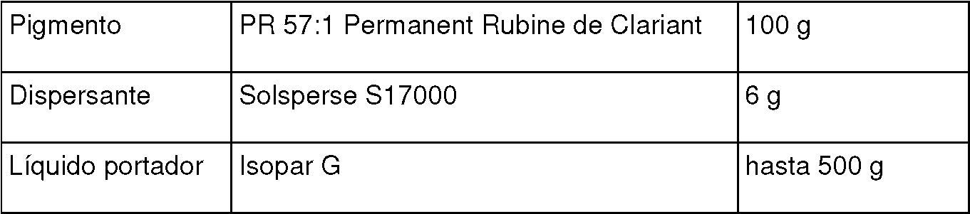
Los ingredientes anteriores se molieron en perlas durante 2 horas. Se mezclaron 300 g de la mezcla resultante con otros 448 g de isopar G y 1,9 g de agente de carga de partículas (Nuxtra Zirconium 6%), para producir una tinta que tiene las siguientes proporciones:The above ingredients were ground into beads for 2 hours. 300 g of the resulting mixture were mixed with another 448 g of isopar G and 1.9 g of particle filler (Nuxtra Zirconium 6%), to produce an ink having the following proportions:
8,00% en peso de pigmento (es decir, partículas marcadoras cargables insolubles);8.00% by weight pigment (ie insoluble chargeable marker particles);
0,48% en peso de un dispersante;0.48% by weight of a dispersant;
0,25% en peso de agente de carga de partículas; y0.25% by weight of particulate filler; Y
91,27% en peso de un líquido portador.91.27% by weight of a carrier liquid.
Las otras tres tintas fueron preparadas por un método similar.The other three inks were prepared by a similar method.
Las cuatro tintas se imprimieron secuencialmente desde cuatro cabezales de impresión del tipo descrito en los documentos WO93/11866, WO97/27058, WO97/27056, WO98/32609, WO01/30576 y WO03/101741, sobre un sustrato de metal con recubrimiento de base blanco que se mueve a una velocidad de 1 m/s en relación con los cabezales de impresión. El ancho de cada cabezal de impresión fue de 172 mm y el ancho de la impresión formada en el sustrato a partir de los cabezales de impresión fue de 160 mm. La imagen era un diseño de cuatro colores que incorporaba texto, gráficos y elementos fotográficos y tenía una resolución de 600 píxeles por pulgada.The four inks were printed sequentially from four print heads of the type described in WO93 / 11866, WO97 / 27058, WO97 / 27056, WO98 / 32609, WO01 / 30576 and WO03 / 101741, on a base coated metal substrate target moving at a speed of 1 m / s relative to the print heads. The width of each printhead was 172mm and the width of the print formed on the substrate from the printheads was 160mm. The image was a four-color layout incorporating text, graphics, and photographic elements, and had a resolution of 600 pixels per inch.
Cada separación de color se formó a partir de cuatro pasadas del sustrato debajo del cabezal de impresión, que tenía un espacio de expulsión de 150 eyectores por pulgada, las cuatro pasadas tardaron un total de 0,8 segundos, con un intervalo de tiempo de 0,2 segundos entre el final de la impresión de un color y comienzo de la impresión del siguiente. Inmediatamente después de la impresión del color final, el sustrato impreso se secó usando una combinación de calentamiento y flujo de aire durante un segundo (para evaporar el líquido portador residual de la impresión). Inmediatamente después de esto, se aplicó un barniz de curado térmico a base de agua al sustrato impreso usando un rodillo anilox, y se curó calentando a 200°C durante cinco minutos. Esto dio un alto nivel de fijación, brillo y resistencia química y a la abrasión al material impreso.Each color separation was formed from four passes of the substrate under the print head, which had an ejection gap of 150 ejectors per inch, the four passes took a total of 0.8 seconds, with a time interval of 0 , 2 seconds between the end of one color printing and the beginning of the next one. Immediately after the final color printing, the printed substrate was dried using a combination of heating and air flow for one second (to evaporate the residual carrier liquid from the printing). Immediately after this, a water-based thermal curing varnish was applied to the printed substrate using an anilox roll, and cured by heating at 200 ° C for five minutes. This gave a high level of fixation, gloss and chemical and abrasion resistance to the printed material.
La impresión logró las siguientes densidades ópticas:The print achieved the following optical densities:
Cian 1,3 ODUCyan 1.3 ODU
Magenta 1,3 ODU Magenta 1.3 ODU
Amarillo 0,9 ODUYellow 0.9 ODU
Negro 2,2 ODUBlack 2.2 ODU
Propiedades adicionales de la impresión terminada fueron:Additional properties of the finished print were:
Seguridad alimentaria: cumple con los códigos SBPIM para imprimir tintas en envoltorios de alimentos.Food Safety - Meets SBPIM codes for printing inks on food packaging.
Durabilidad: cumple con los requisitos exigidos por la industria de latas de bebidas para resistencia al rayado, a los productos químicos y al calor y al cuello y la brida de las latas.Durability - Meets the beverage can industry requirements for scratch, chemical and heat resistance and can neck and flange resistance.
Ejemplo 2Example 2
Usando las mismas tintas que en el Ejemplo 1, las cuatro tintas se imprimieron secuencialmente desde cuatro cabezales de impresión del tipo descrito en los documentos WO93/11866, WO97/27058, WO97/27056, WO98/32609, WO01/30576 y WO03/101741, sobre una película transparente de PET (poli(tereftalato de etileno)) de 12 micrómetros de espesor. La película de PET, que medía aproximadamente 200 mm por 300 mm, se montó sobre una placa metálica plana y horizontal, colocada aproximadamente 0,5 mm debajo de los cabezales de impresión. Se controló que la platina se moviera en relación con los cabezales de impresión repetidamente hacia adelante y atrás a una velocidad de 0,8 metros por segundo en una dirección perpendicular a los conjuntos de cabezales de impresión.Using the same inks as in Example 1, the four inks were printed sequentially from four print heads of the type described in WO93 / 11866, WO97 / 27058, WO97 / 27056, WO98 / 32609, WO01 / 30576 and WO03 / 101741 , on a transparent PET (polyethylene terephthalate) film 12 microns thick. The PET film, measuring approximately 200mm by 300mm, was mounted on a flat, horizontal metal plate, positioned approximately 0.5mm below the print heads. The platen was controlled to move relative to the print heads repeatedly back and forth at a speed of 0.8 meters per second in a direction perpendicular to the print head assemblies.
La imagen a imprimir era un diseño en color de 600 puntos por pulgada que incorpora texto, gráficos e imágenes fotográficas, que miden 100 mm por 160 mm.The image to be printed was a 600 dots per inch color design incorporating text, graphics and photographic images, measuring 100mm by 160mm.
Cada cabezal de impresión tenía 100 mm de ancho y tenía una separación del eyector de 168 micrómetros, de modo que cuatro pasadas del sustrato debajo de un cabezal de impresión creaban una separación de un solo color de 600 puntos por pulgada de la imagen impresa, cada pasada se compensaba en 42 micrómetros del pase anterior. Para lograr esto, se controló un cabezal de impresión a la vez para imprimir durante cada movimiento hacia adelante de la platina y, en cada pasada de retorno de la platina, se controló que el cabezal de impresión se moviera perpendicular al movimiento del sustrato en una distancia de 42 micrómetros.Each printhead was 100mm wide and had an ejector pitch of 168 microns, so that four passes of the substrate under a printhead created a 600 dots per inch single color spacing of the printed image, each pass was offset by 42 micrometers from the previous pass. To accomplish this, one print head was controlled at a time to print during each forward movement of the platen and, on each return pass of the platen, the print head was controlled to move perpendicular to the movement of the substrate by one 42 micron distance.
La imagen en color se imprimió en la película de PET imprimiendo cada una de las cuatro separaciones de color de la manera descrita anteriormente, secuencialmente, con un período de 30 segundos entre la impresión de cada separación de color para permitir que se evapore el líquido portador residual en la impresión. Cada separación de color tardó aproximadamente 4 segundos en imprimirse, y no hubo una fijación intermedia entre los colores. Una vez que se imprimieron los cuatro colores, la imagen impresa se arregló usando Lukas Spray Film Gloss, número 2321, resina acrílica a base de solvente y se dejó secar al aire. La impresión resultante en la película de PET era casi de calidad fotográfica con un alto nivel de fijación, brillo y resistencia química y a la abrasión. The color image was printed on the PET film by printing each of the four color separations in the manner described above, sequentially, with a 30 second period between printing each color separation to allow the carrier liquid to evaporate. residual in the impression. Each color separation took approximately 4 seconds to print, and there was no intermediate fixation between the colors. After all four colors were printed, the printed image was fixed using Lukas Spray Film Gloss, # 2321, solvent based acrylic resin and allowed to air dry. The resulting print on the PET film was near photographic quality with a high level of fixation, gloss, and chemical and abrasion resistance.
Claims (13)
Applications Claiming Priority (2)
| Application Number | Priority Date | Filing Date | Title |
|---|---|---|---|
| EP09170296 | 2009-09-15 | ||
| PCT/EP2010/063472 WO2011032939A1 (en) | 2009-09-15 | 2010-09-14 | Printing process and liquid ink jet ink |
Publications (1)
| Publication Number | Publication Date |
|---|---|
| ES2803244T3 true ES2803244T3 (en) | 2021-01-25 |
Family
ID=41728065
Family Applications (1)
| Application Number | Title | Priority Date | Filing Date |
|---|---|---|---|
| ES10755134T Active ES2803244T3 (en) | 2009-09-15 | 2010-09-14 | Inkjet Liquid Ink and Printing Procedure |
Country Status (10)
| Country | Link |
|---|---|
| US (1) | US9156256B2 (en) |
| EP (1) | EP2478063B1 (en) |
| JP (3) | JP2013504462A (en) |
| KR (2) | KR20120082408A (en) |
| CN (1) | CN102597133B (en) |
| AU (1) | AU2010297367B2 (en) |
| ES (1) | ES2803244T3 (en) |
| PL (1) | PL2478063T3 (en) |
| PT (1) | PT2478063T (en) |
| WO (1) | WO2011032939A1 (en) |
Families Citing this family (16)
| Publication number | Priority date | Publication date | Assignee | Title |
|---|---|---|---|---|
| JP5891602B2 (en) | 2011-04-28 | 2016-03-23 | 東洋製罐株式会社 | Inkjet printing apparatus and seamless can printing method using the same |
| CN102303461A (en) * | 2011-07-11 | 2012-01-04 | 广州南鸥卫浴用品有限公司 | Metal surface pattern printing process |
| US11673155B2 (en) | 2012-12-27 | 2023-06-13 | Kateeva, Inc. | Techniques for arrayed printing of a permanent layer with improved speed and accuracy |
| US12330178B2 (en) | 2012-12-27 | 2025-06-17 | Kateeva, Inc. | Techniques for arrayed printing of a permanent layer with improved speed and accuracy |
| KR20200115664A (en) | 2012-12-27 | 2020-10-07 | 카티바, 인크. | Techniques for print ink volume control to deposit fluids within precise tolerances |
| EP2805826A1 (en) * | 2013-05-20 | 2014-11-26 | Tonejet Limited | Printhead calibration and printing |
| JP6910327B2 (en) * | 2013-06-27 | 2021-07-28 | トーンジェット リミテッド | Printhead control |
| CN107825886B (en) | 2013-12-12 | 2020-04-14 | 科迪华公司 | Method of manufacturing electronic device |
| NL2012603B1 (en) | 2014-04-10 | 2016-05-09 | Xeikon Ip Bv | A method of digitally printing and a digital printing apparatus. |
| GB201407440D0 (en) * | 2014-04-28 | 2014-06-11 | Tonejet Ltd | Printing on cylindrical objects |
| JP6485183B2 (en) * | 2015-04-17 | 2019-03-20 | セイコーエプソン株式会社 | Printing device |
| CN113727856A (en) | 2019-04-26 | 2021-11-30 | 唐杰有限公司 | Device and method for preparing a cylindrical object for decoration thereon |
| US11884058B2 (en) | 2019-10-29 | 2024-01-30 | Hewlett-Packard Development Company, L.P. | Image formation device with radiation fixation |
| CN111746163B (en) * | 2020-06-04 | 2021-11-23 | 中钞印制技术研究院有限公司 | Code printing equipment |
| US11108353B1 (en) | 2020-07-14 | 2021-08-31 | FTC Solar, Inc. | Systems and methods for array level terrain based backtracking |
| CN113199867B (en) * | 2021-04-12 | 2022-06-14 | 华中科技大学 | Electrofluid jet patterning induction method and system |
Family Cites Families (34)
| Publication number | Priority date | Publication date | Assignee | Title |
|---|---|---|---|---|
| US3542682A (en) * | 1968-06-19 | 1970-11-24 | Gaf Corp | Liquid toners for electrostatic printing |
| US4165399A (en) | 1975-11-24 | 1979-08-21 | American Can Company | Binderless ink for jet printing |
| CN85101618A (en) * | 1985-04-01 | 1986-08-20 | 机械工业部天津复印技术研究所 | Carbon black resin colour paste for electrostatic copy printing and manufacture method |
| AU664404B2 (en) | 1991-12-18 | 1995-11-16 | Tonejet Limited | Method and apparatus for the production of discrete agglomerations of particulate matter |
| DE69431436T2 (en) * | 1993-07-01 | 2003-07-31 | Tonejet Corp. Pty. Ltd., Eastwood | LIQUID INK FOR INK JET PRINTING |
| GB9521673D0 (en) * | 1995-10-23 | 1996-01-03 | Xaar Ltd | Ink jet printer dispersion inks |
| GB9601223D0 (en) | 1996-01-22 | 1996-03-20 | The Technology Partnership Plc | Electrode for printer |
| GB9601226D0 (en) | 1996-01-22 | 1996-03-20 | The Technology Partnership Plc | Ejection apparatus and method |
| GB9701318D0 (en) | 1997-01-22 | 1997-03-12 | Tonejet Corp Pty Ltd | Ejection apparatus |
| GB9902386D0 (en) * | 1999-02-04 | 1999-03-24 | Zeneca Ltd | Printing inks |
| EP1095772A1 (en) | 1999-10-25 | 2001-05-02 | Tonejet Corporation Pty Ltd | Printhead |
| JP2002169470A (en) * | 2000-11-27 | 2002-06-14 | Three M Innovative Properties Co | Print display sheet and print display |
| JP2003276323A (en) * | 2002-01-21 | 2003-09-30 | Seiko Epson Corp | Ink jet recorded matter and method for producing the same |
| JP2003251908A (en) | 2002-02-28 | 2003-09-09 | Konica Corp | Inkjet recording method and transfer protective layer |
| EP1366901B1 (en) | 2002-05-31 | 2005-09-14 | Tonejet Limited | Printhead |
| JP2005138503A (en) * | 2003-11-07 | 2005-06-02 | Ricoh Co Ltd | Ink set, image forming apparatus, cartridge, recorded matter |
| JP4051006B2 (en) | 2003-06-19 | 2008-02-20 | 株式会社リコー | Recording material and image forming method using the same |
| JP2005017352A (en) | 2003-06-23 | 2005-01-20 | Fuji Photo Film Co Ltd | Platemaking method of flexographic printing plate |
| JP4114794B2 (en) * | 2003-06-30 | 2008-07-09 | サカタインクス株式会社 | Ink composition for oil-based inkjet recording |
| JP2005035194A (en) * | 2003-07-16 | 2005-02-10 | Toppan Forms Co Ltd | card |
| JP2005059311A (en) * | 2003-08-08 | 2005-03-10 | Seiko Epson Corp | Image protection film and image protection method using the same |
| JP2005081754A (en) * | 2003-09-10 | 2005-03-31 | Konica Minolta Holdings Inc | Inkjet recording method and recorded matter |
| JP4362057B2 (en) | 2003-09-24 | 2009-11-11 | 富士フイルム株式会社 | Inkjet head and inkjet recording apparatus |
| JP2005103958A (en) * | 2003-09-30 | 2005-04-21 | Fuji Photo Film Co Ltd | Inkjet recording method |
| US20050131101A1 (en) | 2003-10-03 | 2005-06-16 | Fuji Photo Film Co., Ltd. | Ink composition and inkjet recording method |
| US20060075917A1 (en) * | 2004-10-08 | 2006-04-13 | Edwards Paul A | Smooth finish UV ink system and method |
| EP1863886B8 (en) | 2005-02-04 | 2013-12-18 | Ricoh Company, Ltd. | Recording ink, ink set, ink cartridge, ink record, inkjet recording apparatus and inkjet recording method |
| JP2006239685A (en) * | 2005-03-04 | 2006-09-14 | Heidelberger Druckmas Ag | Method for inkjet varnishing print |
| JP2006315363A (en) * | 2005-05-16 | 2006-11-24 | Konica Minolta Holdings Inc | Ink jet recording method |
| US7571999B2 (en) | 2005-11-30 | 2009-08-11 | Xerox Corporation | Overcoat compositions, oil-based ink compositions, and processes for ink-jet recording using overcoat and oil-based ink compositions |
| JP4983150B2 (en) * | 2006-04-28 | 2012-07-25 | 東洋インキScホールディングス株式会社 | Method for producing conductive coating |
| DE602006016299D1 (en) * | 2006-11-23 | 2010-09-30 | Agfa Graphics Nv | New radiation-curable compositions |
| JP2009149037A (en) * | 2007-12-21 | 2009-07-09 | Tohoku Ricoh Co Ltd | Coating device in inkjet printing equipment |
| WO2011021591A1 (en) | 2009-08-21 | 2011-02-24 | Ricoh Company, Ltd. | Image forming method, and image formed matter |
-
2010
- 2010-09-14 CN CN201080040809.7A patent/CN102597133B/en not_active Expired - Fee Related
- 2010-09-14 KR KR1020127007033A patent/KR20120082408A/en not_active Ceased
- 2010-09-14 ES ES10755134T patent/ES2803244T3/en active Active
- 2010-09-14 AU AU2010297367A patent/AU2010297367B2/en not_active Ceased
- 2010-09-14 JP JP2012529237A patent/JP2013504462A/en active Pending
- 2010-09-14 EP EP10755134.3A patent/EP2478063B1/en active Active
- 2010-09-14 US US13/261,214 patent/US9156256B2/en not_active Expired - Fee Related
- 2010-09-14 KR KR1020187005608A patent/KR101943281B1/en not_active Expired - Fee Related
- 2010-09-14 PT PT107551343T patent/PT2478063T/en unknown
- 2010-09-14 WO PCT/EP2010/063472 patent/WO2011032939A1/en not_active Ceased
- 2010-09-14 PL PL10755134T patent/PL2478063T3/en unknown
-
2014
- 2014-09-29 JP JP2014198394A patent/JP2015057324A/en active Pending
-
2016
- 2016-10-05 JP JP2016196926A patent/JP2017077728A/en active Pending
Also Published As
| Publication number | Publication date |
|---|---|
| US9156256B2 (en) | 2015-10-13 |
| US20120218362A1 (en) | 2012-08-30 |
| KR20120082408A (en) | 2012-07-23 |
| PL2478063T3 (en) | 2020-11-16 |
| KR101943281B1 (en) | 2019-01-28 |
| CN102597133B (en) | 2018-10-19 |
| CN102597133A (en) | 2012-07-18 |
| JP2015057324A (en) | 2015-03-26 |
| WO2011032939A1 (en) | 2011-03-24 |
| AU2010297367B2 (en) | 2013-08-22 |
| AU2010297367A1 (en) | 2012-03-15 |
| EP2478063B1 (en) | 2020-06-03 |
| EP2478063A1 (en) | 2012-07-25 |
| JP2017077728A (en) | 2017-04-27 |
| PT2478063T (en) | 2020-07-10 |
| JP2013504462A (en) | 2013-02-07 |
| KR20180026554A (en) | 2018-03-12 |
Similar Documents
| Publication | Publication Date | Title |
|---|---|---|
| CN102597133B (en) | Printing method and ink for liquid inkjet | |
| JP3802616B2 (en) | Inkjet recording method | |
| JP3683946B2 (en) | Aqueous pigment ink set for ink jet, recording unit, ink cartridge, and ink jet recording apparatus | |
| ES2966122T3 (en) | Liquid composition, especially ink composition, for binary deviated continuous jet printing, with uncharged droplets, use of said composition, marking method and marked substrate | |
| JP2008105422A (en) | Inkjet printing method which achieves improved image durability and system | |
| JP2006517158A5 (en) | ||
| CN104924736A (en) | Apparatus for Application of gating agent to substrate and image forming set apparatus | |
| JP2017013506A (en) | Film production method, production apparatus and printed matter by ink jet method | |
| US11072197B2 (en) | Method for manufacturing printed matter | |
| CN103358708A (en) | Inkjet recording apparatus and inkjet recording method | |
| JP2005206615A5 (en) | ||
| JP3673582B2 (en) | Black pigment ink, ink set, ink jet recording method, recording unit, ink cartridge, ink jet recording apparatus, and bleed suppression method | |
| JP5655322B2 (en) | Image recording method and image recording apparatus | |
| JP2018001735A (en) | Image recording method and image recording device | |
| JP2001246741A (en) | Printing method of ink jet print and ink set for printer | |
| JPH05104724A (en) | Ink jet recorder | |
| JP2001131451A (en) | Ink composition and printed matter | |
| RU2005123818A (en) | WATER-BASED PAINT, METHOD FOR INJET PAINTING, CARTRIDGE WITH PAINT, UNIT FOR PAINTING, INJECTOR FOR PAINTING AND METHOD FOR FORMING PICTURES | |
| JP2003312119A (en) | Glossy image forming method | |
| JP2002088290A (en) | Ink set, inkjet recording method, cationic black ink, recording unit, ink cartridge, and inkjet recording apparatus | |
| US8602532B2 (en) | Electrowetting mechanism for fluid-application device | |
| JPH11192687A (en) | Image forming method and image forming apparatus | |
| JP2006083295A (en) | Liquid composition and inkjet recording method using the same | |
| JP2006057071A (en) | Ink composition for inkjet recording and inkjet recording method | |
| JP2006089695A (en) | Ink composition and method for ink-jet printing using the same |