ES2805149T3 - State or mode transition trigger based on the transmission of a connection release signaling indication message - Google Patents
State or mode transition trigger based on the transmission of a connection release signaling indication message Download PDFInfo
- Publication number
- ES2805149T3 ES2805149T3 ES10768896T ES10768896T ES2805149T3 ES 2805149 T3 ES2805149 T3 ES 2805149T3 ES 10768896 T ES10768896 T ES 10768896T ES 10768896 T ES10768896 T ES 10768896T ES 2805149 T3 ES2805149 T3 ES 2805149T3
- Authority
- ES
- Spain
- Prior art keywords
- state
- transition
- cell
- indication
- network
- Prior art date
- Legal status (The legal status is an assumption and is not a legal conclusion. Google has not performed a legal analysis and makes no representation as to the accuracy of the status listed.)
- Active
Links
- 230000007704 transition Effects 0.000 title claims abstract description 507
- 230000011664 signaling Effects 0.000 title claims description 275
- 230000005540 biological transmission Effects 0.000 title description 67
- 238000000034 method Methods 0.000 claims abstract description 255
- 238000004891 communication Methods 0.000 claims abstract description 61
- 230000006854 communication Effects 0.000 claims abstract description 61
- 230000008859 change Effects 0.000 claims abstract description 22
- 238000012545 processing Methods 0.000 claims abstract description 7
- 230000008569 process Effects 0.000 claims description 38
- 230000001960 triggered effect Effects 0.000 claims description 17
- 230000002401 inhibitory effect Effects 0.000 claims description 3
- 230000000875 corresponding effect Effects 0.000 description 41
- 230000002159 abnormal effect Effects 0.000 description 33
- 238000012546 transfer Methods 0.000 description 32
- 230000004044 response Effects 0.000 description 24
- 230000006870 function Effects 0.000 description 23
- 238000010586 diagram Methods 0.000 description 21
- 230000000977 initiatory effect Effects 0.000 description 21
- 238000012384 transportation and delivery Methods 0.000 description 21
- 230000005764 inhibitory process Effects 0.000 description 19
- 230000009471 action Effects 0.000 description 15
- 230000007246 mechanism Effects 0.000 description 15
- 230000006399 behavior Effects 0.000 description 13
- 238000007726 management method Methods 0.000 description 13
- 102000018059 CS domains Human genes 0.000 description 12
- 108050007176 CS domains Proteins 0.000 description 12
- 230000000737 periodic effect Effects 0.000 description 10
- 239000002131 composite material Substances 0.000 description 7
- 230000001413 cellular effect Effects 0.000 description 6
- 238000012544 monitoring process Methods 0.000 description 6
- 230000002035 prolonged effect Effects 0.000 description 6
- 230000003068 static effect Effects 0.000 description 6
- 230000004913 activation Effects 0.000 description 5
- 238000006243 chemical reaction Methods 0.000 description 5
- 230000000694 effects Effects 0.000 description 5
- 238000012790 confirmation Methods 0.000 description 4
- 101100219316 Arabidopsis thaliana CYP83B1 gene Proteins 0.000 description 3
- 101100145039 Saccharomyces cerevisiae (strain ATCC 204508 / S288c) RNT1 gene Proteins 0.000 description 3
- 230000008901 benefit Effects 0.000 description 3
- 230000007423 decrease Effects 0.000 description 3
- 238000005516 engineering process Methods 0.000 description 3
- 230000004048 modification Effects 0.000 description 3
- 238000012986 modification Methods 0.000 description 3
- 241000700159 Rattus Species 0.000 description 2
- 206010000210 abortion Diseases 0.000 description 2
- 230000003321 amplification Effects 0.000 description 2
- 238000001514 detection method Methods 0.000 description 2
- 238000001914 filtration Methods 0.000 description 2
- 230000000670 limiting effect Effects 0.000 description 2
- 238000012423 maintenance Methods 0.000 description 2
- 238000005259 measurement Methods 0.000 description 2
- 238000003199 nucleic acid amplification method Methods 0.000 description 2
- 238000013468 resource allocation Methods 0.000 description 2
- FAMLQSCGIQGDPV-UHFFFAOYSA-N 3,4-dihydroxy-6-[4-hydroxy-5-(hydroxymethyl)-2-(sulfooxymethyl)oxolan-3-yl]oxy-5-sulfooxyoxane-2-carboxylic acid Chemical compound OC1C(CO)OC(COS(O)(=O)=O)C1OC1C(OS(O)(=O)=O)C(O)C(O)C(C(O)=O)O1 FAMLQSCGIQGDPV-UHFFFAOYSA-N 0.000 description 1
- 101100365087 Arabidopsis thaliana SCRA gene Proteins 0.000 description 1
- 241001061260 Emmelichthys struhsakeri Species 0.000 description 1
- 101001126226 Homo sapiens Polyisoprenoid diphosphate/phosphate phosphohydrolase PLPP6 Proteins 0.000 description 1
- 101000609849 Homo sapiens [Pyruvate dehydrogenase [acetyl-transferring]]-phosphatase 1, mitochondrial Proteins 0.000 description 1
- 101000609860 Homo sapiens [Pyruvate dehydrogenase [acetyl-transferring]]-phosphatase 2, mitochondrial Proteins 0.000 description 1
- 101150105073 SCR1 gene Proteins 0.000 description 1
- 101150096310 SIB1 gene Proteins 0.000 description 1
- 101100134054 Saccharomyces cerevisiae (strain ATCC 204508 / S288c) NTG1 gene Proteins 0.000 description 1
- 102100039169 [Pyruvate dehydrogenase [acetyl-transferring]]-phosphatase 1, mitochondrial Human genes 0.000 description 1
- 102100039167 [Pyruvate dehydrogenase [acetyl-transferring]]-phosphatase 2, mitochondrial Human genes 0.000 description 1
- 230000006978 adaptation Effects 0.000 description 1
- 238000013459 approach Methods 0.000 description 1
- 238000013475 authorization Methods 0.000 description 1
- 230000009286 beneficial effect Effects 0.000 description 1
- 230000007175 bidirectional communication Effects 0.000 description 1
- 150000001768 cations Chemical class 0.000 description 1
- 238000012508 change request Methods 0.000 description 1
- 230000006835 compression Effects 0.000 description 1
- 238000007906 compression Methods 0.000 description 1
- 238000004590 computer program Methods 0.000 description 1
- 230000001276 controlling effect Effects 0.000 description 1
- 238000013500 data storage Methods 0.000 description 1
- 230000009849 deactivation Effects 0.000 description 1
- 230000006837 decompression Effects 0.000 description 1
- 238000013461 design Methods 0.000 description 1
- 230000004069 differentiation Effects 0.000 description 1
- 239000002360 explosive Substances 0.000 description 1
- 238000009434 installation Methods 0.000 description 1
- 230000003993 interaction Effects 0.000 description 1
- 230000002452 interceptive effect Effects 0.000 description 1
- 150000002500 ions Chemical class 0.000 description 1
- 230000014759 maintenance of location Effects 0.000 description 1
- 238000004519 manufacturing process Methods 0.000 description 1
- 238000010295 mobile communication Methods 0.000 description 1
- 230000002085 persistent effect Effects 0.000 description 1
- 230000002829 reductive effect Effects 0.000 description 1
- 230000002441 reversible effect Effects 0.000 description 1
- 230000005236 sound signal Effects 0.000 description 1
- 241000894007 species Species 0.000 description 1
- 230000001360 synchronised effect Effects 0.000 description 1
- 238000011144 upstream manufacturing Methods 0.000 description 1
- 238000012795 verification Methods 0.000 description 1
- 239000002699 waste material Substances 0.000 description 1
Classifications
-
- H—ELECTRICITY
- H04—ELECTRIC COMMUNICATION TECHNIQUE
- H04W—WIRELESS COMMUNICATION NETWORKS
- H04W76/00—Connection management
- H04W76/20—Manipulation of established connections
- H04W76/27—Transitions between radio resource control [RRC] states
-
- H—ELECTRICITY
- H04—ELECTRIC COMMUNICATION TECHNIQUE
- H04W—WIRELESS COMMUNICATION NETWORKS
- H04W76/00—Connection management
- H04W76/30—Connection release
-
- H—ELECTRICITY
- H04—ELECTRIC COMMUNICATION TECHNIQUE
- H04W—WIRELESS COMMUNICATION NETWORKS
- H04W76/00—Connection management
- H04W76/30—Connection release
- H04W76/32—Release of transport tunnels
Landscapes
- Engineering & Computer Science (AREA)
- Computer Networks & Wireless Communication (AREA)
- Signal Processing (AREA)
- Mobile Radio Communication Systems (AREA)
Abstract
Un metodo para procesar un mensaje de indicacion de transicion que indica un paquete conmutado, PS, Final de sesion de datos por un equipo de usuario, UE, (802), estando el UE en comunicacion con una UTRAN, Red Universal de Acceso de Radio Terrestre, el metodo comprende: en la UE (802): si un recuento de cuantos mensajes de indicacion de transicion se ha activado en el estado actual de control de recursos de radio, RRC, es menor que un numero maximo: incrementar el recuento de cuantos mensajes de indicacion de transicion se han activado en el estado actual de RRC; establecer un elemento de informacion de causa, IE, en un mensaje de indicacion de transicion; enviando el mensaje de indicacion de transicion a la UTRAN; y restablecer el recuento tras la satisfaccion de al menos una condicion de restablecimiento, la al menos una condicion de restablecimiento comprende un cambio de estado de RRC debido a una solicitud de transaccion de datos por parte del UE o la UTRAN, en el que el UE esta configurado para no enviar mensajes de indicacion de transicion posteriores mientras el El UE permanece en el estado de RRC actual si el recuento es mayor que el numero maximo, en el que la causa IE en el mensaje de indicacion de transicion indica una solicitud para el final de una sesion de PS Data.A method for processing a transition indication message indicating a switched packet, PS, End of data session by a user equipment, UE, (802), the UE being in communication with a UTRAN, Universal Radio Access Network Terrestrial, the method comprises: in the EU (802): if a count of how many transition indication messages has been activated in the current state of radio resource control, RRC, is less than a maximum number: increase the count of how many transition indication messages have been activated in the current RRC state; setting a cause information element, IE, in a transition indication message; sending the transition indication message to the UTRAN; and resetting the count after the satisfaction of at least one resetting condition, the at least one resetting condition comprising a RRC state change due to a data transaction request by the UE or UTRAN, wherein the UE is configured not to send subsequent transition indication messages while the UE remains in the current RRC state if the count is greater than the maximum number, in which the IE cause in the transition indication message indicates a request for the end of a PS Data session.
Description
DESCRIPCIÓNDESCRIPTION
Activante de transición de estado o modo sobre la base de la transmisión de un mensaje de indicación de señalización de liberación de conexiónState or mode transition trigger based on the transmission of a connection release signaling indication message
Campo de la divulgaciónDisclosure field
La presente divulgación se refiere al control de recursos de radio entre el Equipo de usuario (UE) u otro dispositivo inalámbrico o móvil y una red inalámbrica, y en particular a la transición entre estados y modos de operación en una red inalámbrica como, por ejemplo, una red del Sistema Universal de Telecomunicaciones Móviles (UMTS).The present disclosure relates to the control of radio resources between the User Equipment (UE) or another wireless or mobile device and a wireless network, and in particular to the transition between states and modes of operation in a wireless network, such as, for example , a network of the Universal Mobile Telecommunications System (UMTS).
AntecedentesBackground
Un Sistema Universal de Telecomunicaciones Móviles (UMTS) es un sistema de banda ancha basado en paquetes para la transmisión de texto, voz digitalizada, video y multimedia. Está altamente suscrito al estándar para la tercera generación y generalmente se basa en el acceso múltiple por división codificada de banda ancha (W-CDMA).A Universal Mobile Telecommunications System (UMTS) is a packet-based broadband system for the transmission of text, digitized voice, video and multimedia. It is highly subscribed to the standard for the third generation and is generally based on broadband encoded division multiple access (W-CDMA).
En una red UMTS, una parte del control de recursos de radio (RRC) de la pila de protocolos es responsable de la asignación, configuración y liberación de recursos de radio entre el UE y la UTRAN. Este protocolo RRC se describe en detalle en las especificaciones 3GPP TS 25.331. Dos modos básicos en los que puede estar el UE se definen como “modo inactivo” y “modo conectado UTRA RRC” (o simplemente “modo conectado”, como se usa aquí). UTRA son las siglas de Acceso de Radio Terrestre o UMTS. En modo inactivo, se requiere que el UE u otro dispositivo móvil solicite una conexión RRC cada vez que desee enviar datos de usuario o en respuesta a una notificación cada vez que la UTRAN o el Nodo de Soporte de Servicio de Radio por Paquetes Generales (GPRS) Servidor (SGSN) lo notifica para recibir datos de una red de datos externa, tal como un servidor push. Los comportamientos del modo inactivo y conectado se describen en detalle en las especificaciones TS 25.304 y TS 25.331 del Proyecto de asociación de tercera generación (3GPP).In a UMTS network, a radio resource control (RRC) part of the protocol stack is responsible for the allocation, configuration and release of radio resources between the UE and the UTRAN. This RRC protocol is described in detail in the 3GPP TS 25.331 specifications. Two basic modes that the UE can be in are defined as "idle mode" and "UTRA RRC connected mode" (or simply "connected mode" as used here). UTRA stands for Terrestrial Radio Access or UMTS. In idle mode, the UE or other mobile device is required to request an RRC connection each time it wishes to send user data or in response to a notification each time the UTRAN or General Packet Radio Service Support Node (GPRS ) Server (SGSN) notifies you to receive data from an external data network, such as a push server. Idle and connected mode behaviors are described in detail in the Third Generation Partnership Project (3GPP) TS 25.304 and TS 25.331 specifications.
Cuando está en un modo conectado UTRA RRC, el dispositivo puede estar en uno de cuatro estados. Estos son: When in a UTRA RRC connected mode, the device can be in one of four states. These are:
CELL-DCH: se asigna un canal dedicado al UE en enlace ascendente y enlace descendente en este estado para intercambiar datos. El UE debe realizar las acciones descritas en 3GPP 25.331.CELL-DCH: A dedicated channel is assigned to the UE in uplink and downlink in this state to exchange data. The UE must perform the actions described in 3GPP 25.331.
CELL_FACH: no se asigna ningún canal dedicado al equipo del usuario en este estado. En cambio, los canales comunes se utilizan para intercambiar una pequeña cantidad de datos en ráfagas. El UE debe realizar acciones como se describe en 3GPP 25.331, que incluye el proceso de selección de celdas como se define en 3GPP TS 25.304.CELL_FACH: No dedicated channel is assigned to the user's computer in this state. Instead, common channels are used to exchange a small amount of data in bursts. The UE must perform actions as described in 3GPP 25.331, which includes the cell selection process as defined in 3GPP TS 25.304.
CELL_PCH: el UE utiliza la recepción discontinua (DRX) para monitorizar mensajes de difusión y notificaciones a través de un canal indicador de notificaciones (PICH). No es posible la actividad de enlace ascendente. El UE debe realizar acciones como se describe en 3GPP 25.331, que incluye el proceso de selección de celdas como se define en 3GPP TS 25.304. El UE debe realizar el procedimiento de CELL UPDATE después de la reselección de celda. CELL_PCH: The UE uses discontinuous reception (DRX) to monitor broadcast messages and notifications through a notification indicator channel (PICH). Uplink activity is not possible. The UE must perform actions as described in 3GPP 25.331, which includes the cell selection process as defined in 3GPP TS 25.304. The UE must perform the CELL UPDATE procedure after cell reselection.
URA_PCH: el UE utiliza la Recepción Discontinua (DRX) para monitorizar mensajes y notificaciones de difusión a través de un Canal Indicador de Notificaciones (PICH). No es posible la actividad de enlace ascendente. El UE debe realizar las acciones descritas en 3GPP 25.331, incluido el proceso de selección de celdas como se define en 3GPP TS 25.304. Este estado es similar a CELL_PCH, excepto que el procedimiento de URA UPDATE solo se activa a través de la reselección del Área de Registro UTRAN (URA).URA_PCH: the UE uses Discontinuous Reception (DRX) to monitor broadcast messages and notifications through a Notification Indicator Channel (PICH). Uplink activity is not possible. The UE must perform the actions described in 3GPP 25.331, including the cell selection process as defined in 3GPP TS 25.304. This state is similar to CELL_PCH, except that the URA UPDATE procedure is only triggered through reselection of the UTRAN Registry Area (URA).
La transición de un modo inactivo al modo conectado y viceversa es controlada por la UTRAN. Cuando un UE en modo inactivo solicita una conexión RRC, la red decide si mover el UE al estado CELL_DCH o CELL_FACH. Cuando el UE está en un modo conectado RRC, nuevamente es la red la que decide cuándo liberar la conexión RRC. La red también puede mover el UE de un estado RRC a otro antes de liberar la conexión o, en algunos casos, en lugar de liberar la conexión. Las transiciones de estado generalmente se activan por la actividad de datos o la inactividad entre el UE y la red. Dado que la red puede no saber cuándo el UE ha completado el intercambio de datos para una aplicación determinada, ésta normalmente mantiene la conexión RRC durante algún tiempo en previsión de más datos hacia/desde el UE. Esto normalmente se hace para reducir la latencia de la configuración de llamadas y la posterior configuración de recursos de radio. El mensaje de liberación de la conexión RRC solo puede ser enviado por la UTRAN. Este mensaje libera la conexión del enlace de señal y todos los recursos de radio entre el UE y la UTRAN. En general, el término “portador de radio” se refiere a los recursos de radio asignados entre el UE y la UTRAN. Y, el término “portador de acceso de radio” generalmente se refiere a recursos de radio asignados entre el UE y, por ejemplo, un SGSN (Nodo de Servicio GPRS Servidor). La presente divulgación, a veces, se referirá al término recurso de radio, y dicho término se referirá, de acuerdo con corresponda, a uno o ambos, el portador de radio y/o el portador de acceso de radio. The transition from an idle to connected mode and vice versa is controlled by the UTRAN. When a UE in idle mode requests an RRC connection, the network decides whether to move the UE to the CELL_DCH or CELL_FACH state. When the UE is in an RRC connected mode, it is again the network that decides when to release the RRC connection. The network can also move the UE from one RRC state to another before releasing the connection or, in some cases, instead of releasing the connection. State transitions are generally triggered by data activity or inactivity between the UE and the network. Since the network may not know when the UE has completed the data exchange for a given application, it normally maintains the RRC connection for some time in anticipation of more data to / from the UE. This is typically done to reduce the latency of call setup and subsequent radio resource setup. The RRC connection release message can only be sent by the UTRAN. This message releases the signal link connection and all radio resources between the UE and the UTRAN. In general, the term "radio bearer" refers to the radio resources allocated between the UE and the UTRAN. And, the term "radio access bearer" generally refers to radio resources allocated between the UE and, for example, an SGSN (GPRS Serving Service Node). The present disclosure will sometimes refer to the term radio resource, and such term will refer, as appropriate, to one or both of the radio bearer and / or the radio access bearer.
El problema con lo anterior es que incluso si una aplicación en el UE ha completado su transacción de datos y no espera ningún intercambio de datos adicional, aún espera a que la red la mueva al estado correcto. La red puede no tener conocimiento del hecho de que la aplicación en el UE ha completado su intercambio de datos. Por ejemplo, una aplicación en el UE puede usar su propio protocolo basado en reconocimiento para intercambiar datos con su servidor de aplicaciones, al que se accede a través de la red central UMTS. Ejemplos son las aplicaciones que se ejecutan sobre el Protocolo de datagramas de usuario/Protocolo de Internet (UDP/IP) que implementan su propia entrega garantizada. En tal caso, el UE sabe si el servidor de aplicaciones ha enviado o recibido todos los paquetes de datos o no y está en una mejor posición para determinar si se va a realizar un intercambio de datos adicional y, por lo tanto, decidir cuándo finalizar la conexión RRC asociada con Dominio del servicio de paquetes (PS). Dado que la UTRAN controla cuándo el estado conectado de RRC se cambia a un estado diferente o en un modo inactivo y la UTRAN no conoce el estado de la entrega de datos entre el UE y el servidor externo, el UE puede verse obligado a permanecer en un estado o modo de velocidad de dato más alto de lo que se requiere, lo que posiblemente reduzca la vida útil de la batería de la estación móvil y posiblemente también desperdicie recursos de red debido al hecho de que los recursos de radio se mantienen ocupados innecesariamente y, por lo tanto, no están disponibles para otro usuario.The problem with the above is that even if an application in the UE has completed its data transaction and is not expecting any additional data exchange, it still waits for the network to move it to the correct state. The network may not be aware of the fact that the application in the UE has completed its data exchange. For example, an application in the UE can use its own handshake-based protocol to exchange data with its application server, which is accessed through the UMTS core network. Examples are applications running over User Datagram Protocol / Internet Protocol (UDP / IP) that implement their own guaranteed delivery. In such a case, the UE knows whether the application server has sent or received all the data packets or not and is in a better position to determine whether an additional data exchange is to be performed and thus decide when to end. the RRC connection associated with the Packet Service Domain (PS). Since the UTRAN controls when the RRC connected state is changed to a different state or an idle mode and the UTRAN does not know the state of the data delivery between the UE and the external server, the UE may be forced to remain in a higher than required data rate state or mode, possibly reducing the battery life of the mobile station and possibly also wasting network resources due to the fact that radio resources are kept unnecessarily busy and therefore they are not available to another user.
Una solución a lo anterior es hacer que el UE envíe una indicación de liberación de señalización a la UTRAN cuando el UE se da cuenta de que ha terminado con una transacción de datos. De conformidad con la sección 8.1.14.3 de la especificación 3GPP TS 25.331, la UTRAN puede liberar la conexión de señalización al recibir la indicación de liberación de señalización del UE, haciendo que el UE pase a un modo inactivo o algún otro estado RRC. Un problema con la solución anterior es que la UTRAN podría inundarse con mensajes de indicación de liberación de señalización del UE y otros UEOne solution to the above is to have the UE send a signaling release indication to the UTRAN when the UE realizes that it has finished with a data transaction. In accordance with section 8.1.14.3 of the 3GPP TS 25.331 specification, the UTRAN may release the signaling connection upon receiving the signaling release indication from the UE, causing the UE to go into an idle mode or some other RRC state. One problem with the above solution is that the UTRAN could be flooded with signaling release indication messages from the UE and other UEs
El documento US 2009/129339 A1 describe un método y un elemento de red para enviar una indicación de transición para hacer la transición de un equipo de usuario a un estado o modo diferente, el método recibe un mensaje de configuración de una red; y transmitiendo una indicación de transición desde el equipo de usuario, la indicación de transición incluye una causa si el mensaje de configuración contiene una indicación de transición de inhibición.Document US 2009/129339 A1 describes a method and a network element to send a transition indication to transition a user equipment to a different state or mode, the method receives a network configuration message; and transmitting a transition indication from the user equipment, the transition indication includes a cause if the configuration message contains an inhibit transition indication.
El documento US 2008/253312 A1 describe que, en un sistema de comunicación móvil WCDMA, cuando la cantidad de tráfico de paquetes transmitidos o recibidos desde un UE disminuye durante un tiempo predeterminado en un estado CELL_DCH en el que se ha establecido una conexión de datos de paquetes WCDMA, el UE pasa a un estado CELL_FACH por un controlador de red de radio (RNC). Posteriormente, se determina si no hay tráfico de paquetes transmitido o recibido durante un cierto tiempo en el estado CELL_FACH (que es un estado RRC en el que se ha conectado una conexión RRC y se ha liberado el canal físico dedicado). Cuando se determina que no hay tráfico de paquetes transmitido o recibido durante el tiempo determinado, el UE solicita una red para liberar la conexión RRC utilizando un mensaje de indicación de liberación de conexión de señalización (SCRI)Document US 2008/253312 A1 describes that, in a WCDMA mobile communication system, when the amount of packet traffic transmitted or received from a UE decreases for a predetermined time in a CELL_DCH state in which a data connection has been established For WCDMA packets, the UE goes into a CELL_FACH state by a radio network controller (RNC). Subsequently, it is determined whether there is no transmitted or received packet traffic for a certain time in the CELL_FACH state (which is an RRC state in which an RRC connection has been connected and the dedicated physical channel has been released). When it is determined that there is no transmitted or received packet traffic during the determined time, the UE requests a network to release the RRC connection using a Signaling Connection Release Indication (SCRI) message
ResumenSummary
Una invención se expone en las reivindicaciones.An invention is set out in the claims.
De acuerdo con un ejemplo, se proporciona un método para procesar un mensaje de indicación por un equipo de usuario, UE, (802), comprendiendo el método: en el UE (802): si las capas superiores indican que no hay más datos conmutados de paquetes, PS, durante un período prolongado; y si un recuento de cuántos mensajes de indicación se han activado en al menos un estado de control de recursos de radio, RRC, es menor que un número máximo: incrementar el recuento de cuántos mensajes de indicación se han activado en al menos un estado de RRC; estableciendo una causa en un mensaje de indicación; y enviando el mensaje de indicación.According to an example, a method is provided for processing an indication message by a user equipment, UE, (802), the method comprising: in the UE (802): if the upper layers indicate that there is no more switched data packet, PS, for an extended period; and if a count of how many indication messages have been activated in at least one radio resource control state, RRC, is less than a maximum number: Increase the count of how many indication messages have activated in at least one state of RRC; establishing a cause in an indication message; and sending the indication message.
De acuerdo con otro ejemplo, se proporciona un equipo de usuario, UE, (802), configurado para procesar mensajes de indicación, el UE (802) configurado para: si las capas superiores indican que no hay más datos conmutados de paquetes, PS, por un período prolongado; y si un recuento de cuántos mensajes de indicación se han activado en al menos un estado de control de recursos de radio, RRC, establezca si es menor que un número máximo: incremente el recuento de cuántos mensajes de indicación se han activado en al menos un estado de RRC; establezca una causa en un mensaje de indicación; y envíe el mensaje de indicación.According to another example, a user equipment, UE, (802) is provided, configured to process indication messages, the UE (802) configured for: if the upper layers indicate that there is no more packet switched data, PS, for a prolonged period; and if a count of how many indication messages have been activated in at least one radio resource control state, RRC, set if it is less than a maximum number: Increase the count of how many indication messages have activated in at least one RRC status; state a cause in an indication message; and send the indication message.
Breve divulgación de los dibujosBrief disclosure of the drawings
La presente divulgación se entenderá mejor con referencia a los dibujos en los que:The present disclosure will be better understood with reference to the drawings in which:
La figura 1 es un diagrama de bloques que muestra estados y transiciones de RRC;Figure 1 is a block diagram showing RRC states and transitions;
La Figura 2 es un esquema de una red UMTS que muestra diversas celdas UMTS y una URA; Figure 2 is a schematic of a UMTS network showing various UMTS cells and a URA;
La Figura 3 es un diagrama de bloques que muestra las diversas etapas en una configuración de conexión RRC; La figura 4A es un diagrama de bloques de una transición de ejemplo entre un estado de modo conectado CELL_DCH y un modo inactivo iniciado por la UTRAN de acuerdo con el método actual;Figure 3 is a block diagram showing the various stages in an RRC connection configuration; FIG. 4A is a block diagram of an exemplary transition between a CELL_DCH connected mode state and a UTRAN initiated idle mode in accordance with the current method;
La Figura 4B es un diagrama de bloques que muestra una transición de ejemplo entre una transición de modo conectado de estado CELL_DCH a un modo inactivo utilizando indicaciones de liberación de señalización;Figure 4B is a block diagram showing an example transition between a connected mode transition from CELL_DCH state to an idle mode using signaling release indications;
La Figura 5A es un diagrama de bloques de una transición de ejemplo entre un estado de inactividad CELL_DCH a un estado de inactividad CELL_FACH a un modo inactivo iniciado por la UTRAN;Figure 5A is a block diagram of an exemplary transition from a CELL_DCH idle state to a CELL_FACH idle state to a UTRAN initiated idle mode;
La Figura 5B es un diagrama de bloques de una transición de ejemplo entre el estado de inactividad CELL_DCH y un modo inactivo que utiliza indicaciones de liberación de señalización;Figure 5B is a block diagram of an exemplary transition between the CELL_DCH idle state and an idle mode using signaling release indications;
La Figura 6 es un diagrama de bloques de una pila de protocolos UMTS;Figure 6 is a block diagram of a UMTS protocol stack;
La Figura 7 es un UE de ejemplo que puede usarse en asociación con el presente método;Figure 7 is an example UE that can be used in association with the present method;
La figura 8 es una red de ejemplo para su uso en asociación con el presente método y sistema;Figure 8 is an example network for use in association with the present method and system;
La Figura 9 es un diagrama de flujo que muestra los pasos de agregar una causa para una indicación de liberación de conexión de señalización en el UE;Figure 9 is a flow chart showing the steps of adding a cause for a signaling connection release indication in the UE;
La Figura 10 es un diagrama de flujo que muestra los pasos tomados por un UE al recibir una indicación de liberación de conexión de señalización que tiene una causa;Figure 10 is a flow chart showing the steps taken by a UE upon receiving a signaling connection release indication that has a cause;
La Figura 11 ilustra una representación gráfica de la asignación de canales físicos y lógicos de ejemploes durante la operación de ejemplo de la red mostrada en la Figura 8 en la que se proporcionan múltiples sesiones simultáneas de servicios de comunicación de datos por paquetes con el UE;Figure 11 illustrates a graphical representation of the example physical and logical channel allocation during the example operation of the network shown in Figure 8 in which multiple simultaneous sessions of packet data communication services are provided with the UE;
La Figura 12 ilustra un diagrama de bloques funcional de UE y elementos de red que proporcionan la función de liberación de recursos de radio para liberar recursos de radio de servicios de datos en paquetes individuales de acuerdo con una realización de la presente divulgación;Figure 12 illustrates a functional block diagram of UE and network elements that provide the radio resource release function to release individual packet data service radio resources in accordance with one embodiment of the present disclosure;
La Figura 13 ilustra un diagrama de secuencia de mensajes representativo de la señalización generada de acuerdo con la operación de una realización de la presente divulgación por la cual liberar la asignación de recursos de radio a un contexto PDP;Figure 13 illustrates a representative message sequence diagram of signaling generated in accordance with the operation of an embodiment of the present disclosure whereby release the allocation of radio resources to a PDP context;
La Figura 14 ilustra un diagrama de secuencia de mensajes, similar al mostrado en la Figura 13, también representativo de la señalización generada de acuerdo con la operación de una realización de la presente divulgación por la cual liberar la asignación de recursos de radio;Figure 14 illustrates a message sequence diagram, similar to that shown in Figure 13, also representative of the signaling generated in accordance with the operation of an embodiment of the present disclosure by which to release the allocation of radio resources;
La Figura 15 ilustra un diagrama de proceso representativo del proceso de una realización de la presente divulgación;Figure 15 illustrates a representative flow chart of the process of one embodiment of the present disclosure;
La Figura 16 ilustra un diagrama de flujo del método que ilustra el método de operación de una realización de la presente divulgación;Figure 16 illustrates a method flow chart illustrating the method of operation of one embodiment of the present disclosure;
La Figura 17 ilustra un diagrama de flujo del método, que también ilustra el método de operación de una realización de la presente divulgación;Figure 17 illustrates a flow chart of the method, which also illustrates the method of operation of one embodiment of the present disclosure;
La figura 18 ilustra un diagrama de flujo del método de una realización en la que se toman decisiones de transición basadas en un perfil de recursos de radio en un elemento de red;Figure 18 illustrates a method flow diagram of an embodiment in which transition decisions are made based on a radio resource profile in a network element;
La Figura 19 ilustra un diagrama de bloques simplificado de un elemento de red capaz de usarse con el método de la Figura 18;Figure 19 illustrates a simplified block diagram of a network element capable of use with the method of Figure 18;
La Figura 20 ilustra un diagrama de flujo de datos para el envío de una indicación de transición o mensaje de solicitud; yFigure 20 illustrates a data flow diagram for sending a transition indication or request message; Y
La figura 21 ilustra un diagrama de flujo de datos para establecer un valor de temporizador de inhibición en un UE. Descripción detalladaFigure 21 illustrates a data flow diagram for setting an inhibit timer value in a UE. Detailed description
Los ejemplos y realizaciones proporcionados a continuación describen diversos métodos y sistemas para la transición de un equipo de usuario (UE) u otro dispositivo móvil entre diversos estados/modos de operación en una red inalámbrica tal como, por ejemplo, una red UMTS. Debe entenderse que también son posibles otras implementaciones en otros tipos de redes. Por ejemplo, las mismas enseñanzas también podrían aplicarse a una red de acceso múltiple por división de código (CDMA) (por ejemplo, 3GPP2 IS-2000), red de banda ancha-CDMA (W-CDMA) (por ejemplo, una red 3GPP UMTS/Acceso a paquetes de alta velocidad (HSPA); una red UTRAN Evolucionada (por ejemplo, LTE), o a modo de generalización, a cualquier red basada en tecnologías de acceso por radio que utilicen recursos de radio controlados por la red o que no mantengan ningún conocimiento del estado de los intercambios de datos a nivel de aplicación del dispositivo. Los ejemplos específicos y las implementaciones que se describen a continuación, aunque se presentan por simplicidad en relación con las redes UMTS, también son aplicables a estos otros entornos de red. Además, el elemento de red a veces se describe a continuación como la UTRAN. Sin embargo, si se utilizan otros tipos de red además de UMTS, el elemento de red se puede seleccionar adecuadamente en función del tipo de red. Además, el elemento de red puede ser la red central en un sistema UMTS o cualquier otro sistema de red apropiado, donde el elemento de red es la entidad que toma las decisiones de transición.The examples and embodiments provided below describe various methods and systems for transitioning a user equipment (UE) or other mobile device between various states / modes of operation in a wireless network such as, for example, a UMTS network. It should be understood that other implementations in other types of networks are also possible. For example, the same teachings could also be applied to a code division multiple access (CDMA) network (eg 3GPP2 IS-2000), broadband-CDMA (W-CDMA) network (eg 3GPP network UMTS / High Speed Packet Access (HSPA); an Evolved UTRAN network (e.g. LTE), or by way of generalization, to any network based on radio access technologies using or not using network controlled radio resources maintain no knowledge of the state of data exchanges at the device application level. The specific examples and implementations described below, while presented for simplicity in relation to UMTS networks, are also applicable to these other network environments In addition, the network element is sometimes described below as UTRAN. However, if other network types are used than UMTS, the network element can be appropriately selected based on the network type. In addition, the e Network element can be the core network in a UMTS system or any other appropriate network system, where the network element is the entity that makes the transition decisions.
En un ejemplo particular, el presente sistema y método proporcionan la transición de un modo conectado RRC a un estado o modo más eficiente de batería o de recursos de radio mientras que proporciona capacidades de toma de decisiones en la red. En particular, el presente método y aparato proporcionan una transición basada en la recepción de una indicación de un UE que indica, implícita o explícitamente, que una transición del estado o modo RRC asociado con una conexión de señalización particular con recursos de radio a otro estado o modo debería ocurrir. Como se apreciará, dicha indicación o solicitud de transición podría utilizar una comunicación existente bajo los estándares actuales, por ejemplo, un mensaje de SIGNALING CONNECTION RELEASE INDICATION, o podría ser un nuevo mensaje dedicado para cambiar el estado del UE, como una “solicitud de estado RRC preferido” o un “mensaje de indicación de transferencia de datos completa”. Un mensaje de indicación de transferencia de datos completa es un mensaje que indica la finalización de la transferencia de datos de capa superior. Como se usa en este documento, una indicación podría referirse a cualquier escenario, y podría incorporar una solicitud.In a particular example, the present system and method provide for the transition from an RRC connected mode to a more efficient battery or radio resource state or mode while providing decision-making capabilities in the network. In particular, the present method and apparatus provide a transition based on the receipt of an indication from a UE indicating, implicitly or explicitly, that a transition from the RRC state or mode associated with a particular signaling connection with radio resources to another state o mode should occur. As will be appreciated, such an indication or request for transition could use an existing communication under current standards, for example a SIGNALING CONNECTION RELEASE INDICATION message, or it could be a new message dedicated to changing the state of the UE, such as a "request for Preferred RRC status ”or a“ data transfer complete indication message ”. A data transfer complete indication message is a message indicating the completion of the upper layer data transfer. As used in this document, an indication could refer to any scenario, and could incorporate a request.
La indicación de transición originada por el UE puede enviarse en algunas situaciones cuando una o más aplicaciones en el UE han completado un intercambio de datos y/o cuando se determina que no se espera que las aplicaciones del UE intercambien cualquier otro dato. El elemento de red puede usar la indicación y cualquier información provista en el mismo, así como otra información relacionada con el recurso de radio, como la calidad del servicio, el Nombre del punto de acceso (APN), el contexto del protocolo de datos en paquetes (PDP), la información histórica, entre otros, definidos aquí como un perfil de recursos de radio, para tomar una decisión específica de la red sobre si se debe hacer la transición del dispositivo móvil a otro modo o estado, o no hacer nada. La indicación de transición proporcionada por el UE o dispositivo móvil puede tomar diversas formas y puede enviarse en diferentes condiciones. En un primer ejemplo, la indicación de transición se puede enviar en función de un estado compuesto de todas las aplicaciones que residen en el UE. Específicamente, en un entorno UMTS, si una aplicación en el UE determina que se hace con el intercambio de datos, puede enviar una indicación de “hecho” a un componente de “administrador de conexión” del software del UE. El administrador de conexión puede, en una realización, realizar un seguimiento de todas las aplicaciones existentes (incluidas las que proporcionan un servicio a través de uno o múltiples protocolos), contextos de protocolo de datos de paquetes (PDP) asociados, recursos de radio de paquetes conmutados (PS) asociados y recursos de radio de circuitos conmutados (CS) asociados. Un contexto PDP es una asociación lógica entre un UE y una PDN (red pública de datos) que se ejecuta en una red central UMTS. Una o diversas aplicaciones (por ejemplo, una aplicación de correo electrónico y una aplicación de navegador) en el UE pueden estar asociadas con un contexto PDP. En algunos casos, una aplicación en el UE está asociada con un contexto PDP primario y múltiples aplicaciones pueden estar atadas con contextos PDP secundarios. El Administrador de conexión recibe indicaciones de “hecho” de diferentes aplicaciones en el UE que están activas simultáneamente. Por ejemplo, un usuario puede recibir un correo electrónico de un servidor push mientras navega por la web. Después de que la aplicación de correo electrónico haya enviado un acuse de recibo, puede indicar que ha completado su transacción de datos. La aplicación del navegador puede comportarse de manera diferente y, en su lugar, hacer una determinación predictiva (por ejemplo, utilizando un temporizador de inactividad) de cuándo enviar una indicación de “hecho” al administrador de conexión.The UE originated transition indication may be sent in some situations when one or more applications in the UE have completed a data exchange and / or when it is determined that the UE applications are not expected to exchange any other data. The network element can use the indication and any information provided in it, as well as other information related to the radio resource, such as the quality of service, the Access Point Name (APN), the context of the data protocol in packets (PDP), historical information, among others, defined here as a radio resource profile, to make a network-specific decision on whether to transition the mobile device to another mode or state, or do nothing . The transition indication provided by the UE or mobile device can take various forms and can be sent under different conditions. In a first example, the transition indication can be sent based on a composite state of all applications residing in the UE. Specifically, in a UMTS environment, if an application in the UE determines that it is done with the data exchange, it can send a "done" indication to a "connection manager" component of the UE software. The connection manager may, in one embodiment, keep track of all existing applications (including those that provide a service over one or multiple protocols), associated packet data protocol (PDP) contexts, radio resources from associated packet switched (PS) and associated circuit switched (CS) radio resources. A PDP context is a logical association between a UE and a PDN (public data network) running on a UMTS core network. One or more applications (eg an email application and a browser application) in the UE may be associated with a PDP context. In some cases, an application in the UE is associated with a primary PDP context and multiple applications may be tied with secondary PDP contexts. The Connection Manager receives "done" indications from different applications in the UE that are active simultaneously. For example, a user can receive an email from a push server while browsing the web. After the email application has sent an acknowledgment, it can indicate that it has completed your data transaction. The browser application may behave differently and instead make a predictive determination (eg, using an idle timer) of when to send a "done" indication to the connection manager.
En base a un estado compuesto de tales indicaciones de aplicaciones activas, el software de UE puede decidir enviar una indicación de transición para indicar o solicitar a la red que se produzca una transición de un estado o modo a otro. Alternativamente, el software UE puede esperar antes de enviar la indicación de transición e introducir un retraso para garantizar que la aplicación haya terminado realmente con el intercambio de datos y no requiera mantenimiento en un estado o modo intensivo de recursos de batería o radio. El retraso puede ser dinámico de acuerdo con el historial de tráfico y/o los perfiles de la aplicación. Siempre que el administrador de conexión determine con cierta probabilidad que no se espera que ninguna aplicación intercambie datos, puede enviar una indicación de transición a la red para indicar que debería ocurrir una transición. En un ejemplo específico, la indicación de transición puede ser una indicación de liberación de conexión de señalización para el dominio apropiado (por ejemplo, dominio PS) para solicitar una transición a un modo inactivo. Alternativamente, la indicación de transición podría ser una solicitud de transición de estado dentro del modo conectado a la UTRAN.Based on a state composed of such active application indications, the UE software may decide to send a transition indication to indicate or request the network to transition from one state or mode to another. Alternatively, the UE software may wait before sending the transition indication and introduce a delay to ensure that the application has actually finished exchanging data and does not require maintenance in a battery or radio resource intensive state or mode. The delay can be dynamic according to traffic history and / or application profiles. As long as the connection manager determines with some probability that no application is expected to exchange data, it can send a transition indication to the network to indicate that a transition should occur. In a specific example, the transition indication may be a signaling connection release indication for the domain appropriate (eg PS domain) to request a transition to an idle mode. Alternatively, the transition indication could be a request for a state transition within the UTRAN connected mode.
Como se describe a continuación con más detalle, basándose en la recepción de una indicación de transición y, opcionalmente, un perfil de recursos de radio, un elemento de red como la UTRAN en un entorno UMTS puede decidir la transición del UE de un estado o modo a otro.As described in more detail below, based on the receipt of a transition indication and optionally a radio resource profile, a network element such as UTRAN in a UMTS environment can decide the transition of the UE from a state or mode to another.
Otras indicaciones de transición son posibles. Por ejemplo, en lugar de confiar en un estado compuesto de todas las aplicaciones activas en el UE, el software del UE puede, en una realización alternativa, enviar una indicación de transición cada vez que una aplicación del UE ha completado un intercambio o datos y/o la aplicación no espera intercambiar más datos. En este caso, el elemento de red (por ejemplo, la UTRAN), basado en un perfil de recursos de radio opcional para el UE como se describe con referencia a la Figura 18 a continuación, puede utilizar la indicación para tomar una decisión de transición.Other transition indications are possible. For example, instead of relying on a composite state of all applications active in the UE, the UE software may, in an alternative embodiment, send a transition indication each time a UE application has completed an exchange or data and / or the application does not expect to exchange more data. In this case, the network element (e.g. UTRAN), based on an optional radio resource profile for the UE as described with reference to Figure 18 below, can use the indication to make a transition decision .
En otro ejemplo más, la indicación de transición podría simplemente indicar que una o más aplicaciones en el UE completaron un intercambio de datos y/o que no se espera que las aplicaciones del UE intercambien ningún otro dato. Sobre la base de esa indicación y un perfil de recursos de radio opcional para el UE, la red (por ejemplo, UTRAN), puede decidir si transita o no el UE a un estado, modo u operación más apropiados.In yet another example, the transition indication could simply indicate that one or more applications in the UE completed a data exchange and / or that the UE applications are not expected to exchange any other data. Based on that indication and an optional radio resource profile for the UE, the network (eg UTRAN) can decide whether or not to transition the UE to a more appropriate state, mode or operation.
En otro ejemplo, la indicación de transición podría ser implícita en lugar de explícita. Por ejemplo, la indicación puede ser parte de un reporte de estado enviado periódicamente. Tal reporte de estado podría incluir información como si una memoria intermedia de enlace de radio tiene datos o podría incluir información sobre el tráfico saliente. In another example, the transition indication could be implicit instead of explicit. For example, the indication can be part of a status report sent periodically. Such a status report could include information such as whether a radio link buffer has data or it could include information about outgoing traffic.
Cuando el UE envía una indicación de transición, puede incluir información adicional para ayudar al elemento de red a tomar la decisión de actuar sobre la indicación. Esta información adicional incluiría el motivo o la causa para que el UE envíe el mensaje. Esta causa o razón (explicada a continuación con mayor detalle) se basaría en que el UE determine la necesidad de un comportamiento similar a la “latencia rápida”. Dicha información adicional puede ser por medio de un nuevo elemento de información o un nuevo parámetro dentro del mensaje de indicación de transición.When the UE sends a transition indication, it may include additional information to assist the network element in making the decision to act on the indication. This additional information would include the reason or cause for the UE to send the message. This cause or reason (explained in more detail below) would be based on the UE determining the need for behavior similar to "fast latency". Said additional information may be by means of a new information element or a new parameter within the transition indication message.
En una realización adicional, podría existir un temporizador en el UE para garantizar que no se pueda enviar una indicación de transición hasta que haya transcurrido un tiempo (inhibir la duración) desde que se envió una indicación de transición previa. Este temporizador de inhibición restringe que el UE envíe el mensaje de indicación de transición con demasiada frecuencia y además permite que la red tome una decisión confiando en los mensajes que se activan solo con una frecuencia máxima dada. La duración del tiempo podría ser determinada por un temporizador cuyo valor esté preconfigurado o establecido por una red (indicada o señalada). Si el valor lo establece una red, podría transmitirse en mensajes nuevos o existentes, como Solicitud de conexión RRC, Liberación de conexión RRC, Configuración del portador de radio, Información de movilidad UTRAN o un Bloque de información del sistema, entre otros, y podría ser un elemento de información en esos mensajes. El valor podría transmitirse alternativamente en una porción de indicación de transición de inhibición de un mensaje de configuración de conexión RRC enviado por la UTRAN en respuesta a un mensaje de solicitud de conexión RRC recibido del UE, por ejemplo.In a further embodiment, there could be a timer in the UE to ensure that a transition indication cannot be sent until a time (inhibit duration) has elapsed since a previous transition indication was sent. This inhibit timer restricts the UE from sending the transition indication message too often and further allows the network to make a decision relying on messages that are triggered only with a given maximum frequency. The length of time could be determined by a timer whose value is preconfigured or set by a network (indicated or indicated). If the value is set by a network, it could be transmitted in new or existing messages, such as RRC Connection Request, RRC Connection Release, Radio Bearer Configuration, UTRAN Mobility Information, or a System Information Block, among others, and could be an information element in those messages. The value could alternatively be transmitted in an inhibit transition indication portion of an RRC connection setup message sent by the UTRAN in response to an RRC connection request message received from the UE, for example.
En una realización alternativa, el valor podría transmitirse a un UE en un mensaje cuyo tipo depende de un estado del UE. Por ejemplo, la red podría enviar el valor a todos los UE en una celda como una porción de un mensaje de información del sistema que el UE lee cuando está en un estado IDLE, URA_PCH, Cell_PCH o CELL_FACH.In an alternative embodiment, the value could be transmitted to a UE in a message whose type depends on a state of the UE. For example, the network could send the value to all UEs in a cell as a portion of a system information message that the UE reads when it is in an IDLE, URA_PCH, Cell_PCH, or CELL_FACH state.
En otra realización más, el valor podría enviarse como una porción de un mensaje de configuración de conexión RRC.In yet another embodiment, the value could be sent as a portion of an RRC connection setup message.
Los mensajes generados por la red también pueden transmitir un valor de temporizador de inhibición implícito a través de la no inclusión de un temporizador de inhibición en el mensaje o en un elemento de información dentro del mensaje. Por ejemplo, al determinar que se omite un temporizador de inhibición de un mensaje recibido, un UE aplica un valor predeterminado para su uso como un valor de temporizador de inhibición. Un uso de ejemplo de la omisión de inhibición del valor del temporizador es prohibir que el UE envíe un mensaje de indicación de transición. En tal situación, cuando un UE detecta la omisión de un valor de temporizador de inhibición esperado en un mensaje recibido, el UE puede, en función de la omisión, tener prohibido enviar cualquier mensaje de indicación de transición. Una manera de lograr esto es que el UE adopte un valor de temporizador de inhibición de infinito.Network generated messages may also convey an implicit inhibit timer value through the non-inclusion of an inhibit timer in the message or in an information element within the message. For example, when determining that an inhibit timer is skipped from a received message, a UE applies a predetermined value for use as an inhibit timer value. An example use of bypassing the timer value is to prohibit the UE from sending a transition indication message. In such a situation, when a UE detects the omission of an expected inhibit timer value in a received message, the UE may, based on the omission, be prohibited from sending any transition indication messages. One way to achieve this is for the UE to adopt an inhibit timer value of infinity.
En otra realización, cuando el UE detecta la omisión de un valor de temporizador de inhibición (y, por ejemplo, adopta un valor de temporizador de inhibición de infinito), puede enviar indicaciones de transición, pero sin incluir ninguna información adicional, específicamente puede omitir la causa de activar el envío de la indicación de transición (se describe más detalladamente a continuación con mayor detalle). La omisión de un elemento de causa en un mensaje de indicación de transición puede garantizar la compatibilidad con versiones anteriores al permitir que los UE utilicen un mensaje de indicación de transición existente (por ejemplo, SIGNALING CONNECTION RELEASE INDICATION) para solicitar o indicar una transición.In another embodiment, when the UE detects the omission of an inhibit timer value (and, for example, adopts an inhibit timer value of infinity), it may send transition indications, but without including any additional information, specifically it may omit the cause of triggering the sending of the transition indication (described in more detail below in more detail). The omission of an element of cause in a transition indication message, you can ensure backward compatibility by allowing UEs to use an existing transition indication message (eg, SIGNALING CONNECTION RELEASE INDICATION) to request or indicate a transition.
La no inclusión de un temporizador de inhibición en el mensaje recibido se detalla adicionalmente con referencia a una realización de ejemplo en la que un bloque de información del sistema se transmite en una celda, o se envía a un UE y el bloque de información del sistema está configurado para transmitir un valor del temporizador de inhibición. En esta realización, si el UE recibe un bloque de información del sistema que no contiene un temporizador de inhibición, conocido como T3xx, en el mensaje o un elemento de información dentro del mensaje, en cuyo caso el UE puede determinar no permitir que el UE envíe el mensaje de indicación de transición, por ejemplo, configurando el temporizador de inhibición, T3xx, en infinito.The non-inclusion of an inhibit timer in the received message is further detailed with reference to an example embodiment in which a system information block is transmitted in a cell, or sent to a UE and the system information block is configured to transmit an inhibit timer value. In this embodiment, if the UE receives a block of information from the system that does not contain an inhibit timer, known as T3xx, in the message or an information element within the message, in which case the UE may determine not to allow the UE send the transition indication message, for example, by setting the inhibit timer, T3xx, to infinity.
La no inclusión de un temporizador de inhibición se detalla adicionalmente con referencia a otra realización de ejemplo en la que se omite un temporizador de inhibición, T3xx, de un mensaje de información de movilidad UTRAN. En tal situación, un UE receptor puede continuar aplicando un valor de temporizador de inhibición almacenado previo. Alternativamente, el UE, al detectar la omisión del temporizador de inhibición T3xx, puede determinar no permitir que el UE envíe el mensaje de indicación de transición, por ejemplo, configurando el temporizador de inhibición, T3xx, en infinito.The non-inclusion of an inhibit timer is further detailed with reference to another exemplary embodiment in which an inhibit timer, T3xx, is omitted from a UTRAN mobility information message. In such a situation, a receiving UE may continue to apply a previous stored inhibit timer value. Alternatively, the UE, upon detecting the omission of the inhibit timer T3xx, may determine not to allow the UE to send the transition indication message, for example, by setting the inhibit timer, T3xx, to infinity.
En otra realización de ejemplo más, un UE, al detectar la omisión de un temporizador de inhibición en el mensaje recibido o en un elemento de información dentro del mensaje, establece el valor del temporizador de inhibición en otro valor predeterminado (por ejemplo, uno de 0 segundos, 5 segundos, 10 segundos, 15 segundos, 20 segundos, 30 segundos, 1 minuto, 1 minuto 30 segundos, 2 minutos). Alternativamente o, además, estos ejemplos pueden aplicarse a otros mensajes generados por la red.In yet another exemplary embodiment, a UE, upon detecting the omission of an inhibit timer in the received message or in an information element within the message, sets the value of the inhibit timer to another predetermined value (e.g., one of 0 seconds, 5 seconds, 10 seconds, 15 seconds, 20 seconds, 30 seconds, 1 minute, 1 minute 30 seconds, 2 minutes). Alternatively or in addition, these examples can be applied to other messages generated by the network.
En otras realizaciones, si el temporizador de inhibición (valor) no se envía o señaliza al UE en un mensaje o elemento de información, o el temporizador de inhibición no se lee de la información del sistema de difusión ni se recibe de otros mensajes UTRAN dedicados al hacer la transición desde de una celda a otra, el envío de una indicación de transición puede o no ocurrir.In other embodiments, if the inhibit timer (value) is not sent or signaled to the UE in a message or information item, or the inhibit timer is not read from the broadcast system information or received from other dedicated UTRAN messages When transitioning from one cell to another, the sending of a transition indication may or may not occur.
Específicamente en una realización, el UE al detectar que no hay presente un temporizador de inhibición, no inicia una indicación de transición basada en una capa superior que determina que no tiene más datos PS para transmitir. Specifically in one embodiment, the UE upon detecting that an inhibit timer is not present, does not initiate a transition indication based on an upper layer determining that it has no more PS data to transmit.
En una realización alternativa, el UE al detectar que no hay presente un temporizador de inhibición, puede iniciar una indicación de transición basada en la capa superior que determina que no tiene más datos PS para transmitir. In an alternative embodiment, the UE upon detecting that an inhibit timer is not present, may initiate a transition indication based on the upper layer determining that it has no more PS data to transmit.
En otra realización más, si no se recibe ningún valor de temporizador de la UTRAN dentro de un mensaje, o dentro de un elemento de información en un mensaje (a través de difusión o de otro modo), en lugar de establecer el valor del temporizador en el UE en infinito, el UE puede establecer el temporizador de inhibición en cero o, alternativamente, eliminar cualquier configuración para el temporizador, y en su lugar se le permitirá enviar una indicación de transición. En este caso, el UE podría omitir o tener prohibido adjuntar una causa en el mensaje de indicación de transición. En una realización, se usa un mensaje SIGNALING CONNECTION RELEASE INDICATION como un ejemplo de una indicación de transición.In yet another embodiment, if no timer value is received from the UTRAN within a message, or within an information element in a message (via broadcast or otherwise), instead of setting the timer value in the UE at infinity, the UE may set the inhibit timer to zero or, alternatively, remove any settings for the timer, and will instead be allowed to send a transition indication. In this case, the UE could omit or be prohibited from attaching a cause in the transition indication message. In one embodiment, a SIGNALING CONNECTION RELEASE INDICATION message is used as an example of a transition indication.
En una realización, la indicación de transición se transmite usando el procedimiento de indicación de liberación de conexión de señalización. El UE utiliza el procedimiento de indicación de liberación de la conexión de señalización para indicar a la UTRAN que se ha liberado una de sus conexiones de señalización.In one embodiment, the transition indication is transmitted using the signaling connection release indication procedure. The UE uses the signaling connection release indication procedure to indicate to the UTRAN that one of its signaling connections has been released.
Específicamente de acuerdo con TS 25.331 Sección 8.1.14.2, el UE, al recibir una solicitud para liberar la conexión de señalización desde las capas superiores para un dominio CN específico, verificará si existe la conexión de señalización en la variable “ESTABLISHED_SIGNALLING_CONNECTIONS para el dominio CN específico identificado en el elemento de información “identidad de dominio CN”. Si es así, el UE puede iniciar el procedimiento de indicación de liberación de conexión de señalización.Specifically according to TS 25.331 Section 8.1.14.2, the UE, upon receiving a request to release the signaling connection from the upper layers for a specific CN domain, will check if the signaling connection exists in the variable “ESTABLISHED_SIGNALLING_CONNECTIONS for the CN domain specific identified in the information element "CN domain identity". If so, the UE may initiate the signaling connection release indication procedure.
En el caso de que el valor del temporizador de inhibición no se señale o se transmita de otra forma al UE, no se especifica ninguna causa de indicación de liberación de conexión de señalización en el mensaje SIGNALING CONNECTION RELEASE INDICATION. Los expertos en la materia apreciarán que en esta realización alternativa la falta de un valor de temporizador no da como resultado que el valor del temporizador se establezca en infinito. In the case that the inhibit timer value is not signaled or otherwise transmitted to the UE, no signaling connection release indication cause is specified in the SIGNALING CONNECTION RELEASE INDICATION message. Those skilled in the art will appreciate that in this alternative embodiment the lack of a timer value does not result in the timer value being set to infinity.
En el lado de la UTRAN, al recibir un mensaje de SIGNALING CONNECTION RELEASE INDICATION sin una causa, la UTRAN indica la liberación de la conexión de señalización para la identidad de dominio CN identificada a las capas superiores. Esto puede entonces iniciar la liberación de la conexión de control de recursos de radio establecida. On the UTRAN side, upon receiving a SIGNALING CONNECTION RELEASE INDICATION message without a cause, the UTRAN indicates the release of the signaling connection for the identified CN domain identity to the upper layers. This can then initiate the release of the established radio resource control connection.
En otra realización alternativa, cuando la UTRAN señala o transmite un valor de temporizador al UE, por ejemplo, inhibe el temporizador T3xx en el elemento de información “temporizadores y constantes de UE en modo conectado” (o usando información del sistema, tal como SIB1, SIB3 o SIB4, o con un mensaje de información de movilidad UTRAN dedicado), el procedimiento de liberación se realiza de acuerdo con lo siguiente. Primero, el UE puede verificar si hay alguna conexión de dominio de circuitos conmutados indicada. Dichas conexiones pueden indicarse en la variable “ESTABLISHED_-SIGNALLING_CONNECTIONS”. Si no hay conexiones de dominio de circuitos conmutados, una segunda verificación para determinar si una capa superior indica que no habrá datos de dominio con conmutación de paquetes durante un período prolongado.In another alternative embodiment, when the UTRAN signals or transmits a timer value to the UE, for example, it inhibits timer T3xx in the information element "UE timers and constants in connected mode" (or using system information, such as SIB1 , SIB3 or SIB4, or with a dedicated UTRAN mobility information message), the release procedure is performed according to the following. First, the UE can check if there is any indicated circuit switched domain connection. These connections can be indicated in the variable "ESTABLISHED_-SIGNALLING_CONNECTIONS". If there are no circuit-switched domain connections, a second check to determine if an upper layer indicates that there will be no packet-switched domain data for an extended period.
Si no hay conexiones de dominio de circuito conmutado y no se esperan datos de dominio de paquete conmutado durante un período prolongado, el UE puede verificar a continuación si el temporizador T3xx está funcionando. If there are no circuit switched domain connections and no packet switched domain data is expected for an extended period, the UE can then check if timer T3xx is running.
Si el temporizador T3xx no está funcionando, el UE establece el elemento de información “Identidad de dominio CN” en el dominio de paquetes conmutados (PS). Además, el elemento de información “Causa de indicación de liberación de conexión de señalización” se establece en “Fin de sesión de datos de PS solicitada por el UE”. El mensaje SIGNALING CONNECTION RELEASE INDICATION se transmite en el DCCH utilizando AM RLC. Además, después de la transmisión, se inicia el temporizador T3xx.If timer T3xx is not running, the UE sets the "CN Domain Identity" information element in the packet switched (PS) domain. Also, the information element "Signaling connection release indication cause" is set to "End of PS data session requested by UE". The SIGNALING CONNECTION RELEASE INDICATION message is transmitted on the DCCH using AM RLC. Also, after transmission, timer T3xx starts.
El procedimiento anterior finaliza con la entrega exitosa del mensaje SIGNALING CONNECTION RELEASE INDICATION, de acuerdo con lo confirmado por el RLC en el procedimiento anterior. En esta realización, se inhibe que el UE envíe el mensaje SIGNALING CONNECTION RELEASE INDICATION con una causa de indicación de liberación de conexión de señalización establecida en “Finalización de sesión de datos de PS solicitada por el UE” mientras el temporizador T3xx está funcionando o hasta que el temporizador T3xx ha expirado.The previous procedure ends with the successful delivery of the SIGNALING CONNECTION RELEASE INDICATION message, as confirmed by the RLC in the previous procedure. In this embodiment, the UE is inhibited from sending the SIGNALING CONNECTION RELEASE INDICATION message with a signaling connection release indication cause set to "UE requested PS data session end" while timer T3xx is running or until that timer T3xx has expired.
Cuando el temporizador T3xx está funcionando, si el procedimiento de indicación de liberación de conexión de señalización se inicia debido a que no hay más datos de dominio conmutados por paquetes durante un período prolongado, el UE es responsable de implementar si se iniciará el procedimiento al expirar el temporizador T3xx. La decisión del UE puede basarse en determinar si tiene alguna indicación de liberación de conexión de señalización posterior o solicitar mensajes para enviar y, de ser así, la decisión del UE puede incluir volver a verificar algunas o todas las mismas comprobaciones para iniciar el procedimiento como se describe aquí.When timer T3xx is running, if the signaling connection release indication procedure is started due to no more packet-switched domain data for a long period, the UE is responsible for implementing whether to start the procedure upon expiration the T3xx timer. The UE's decision may be based on determining whether it has any subsequent signaling connection release indication or requesting messages to send, and if so, the UE's decision may include reverifying some or all of the same checks to initiate the procedure as described here.
En el lado de UTRAN, si el mensaje de SIGNALING CONNECTION RELEASE INDICATION recibido no incluye una causa de indicación de liberación de conexión de señalización, la UTRAN puede solicitar la liberación de la conexión de señalización desde una capa superior y la capa superior puede entonces iniciar la liberación de la conexión de señalización. Si, por otro lado, el mensaje SIGNALING CONNECTION RELEASE INDICATION recibido incluye una causa, la UTRAN puede liberar la conexión de señalización o iniciar una transición de estado a un estado más eficiente de la batería (por ejemplo, CELL_FACH, CELL_PCH, URA_PCH o IDLE_MODE).On the UTRAN side, if the received SIGNALING CONNECTION RELEASE INDICATION message does not include a signaling connection release indication cause, the UTRAN may request the release of the signaling connection from an upper layer and the upper layer may then initiate the release of the signaling connection. If, on the other hand, the received SIGNALING CONNECTION RELEASE INDICATION message includes a cause, the UTRAN can release the signaling connection or initiate a state transition to a more efficient battery state (for example, CELL_FACH, CELL_PCH, URA_PCH or IDLE_MODE ).
La duración de inhibición anterior puede basarse en el estado al que el UE quisiera hacer la transición. Por ejemplo, la duración de la inhibición puede ser diferente, ya sea que el móvil indique su última preferencia para algunos Estados/modos de RRC frente a otros. Por ejemplo, podría ser diferente si el móvil indica una preferencia por el modo inactivo, frente a los estados Cell_FACH o frente a Cell_PCH/URA PCH. En el caso de que la red establezca la duración de inhibición, esto puede lograrse mediante la red que indica/envía dos (o más) conjuntos de valores al móvil, que se utilizarán de acuerdo con el escenario. Alternativamente, la indicación podría hacerse de tal manera que el valor de duración de inhibición apropiado solo se indique/señale al móvil: por ejemplo, si el UE desea hacer la transición a Cell_PCH, se podría establecer una duración de tiempo transcurrido diferente que si el UE quiere hacer la transición a inactivo.The above inhibit duration can be based on the state the UE would like to transition to. For example, the duration of the inhibit may be different, whether the mobile indicates its last preference for some RRC states / modes over others. For example, it could be different if the mobile indicates a preference for idle mode, versus Cell_FACH states or Cell_PCH / URA PCH states. In the case where the inhibit duration is set by the network, this can be achieved by the network indicating / sending two (or more) sets of values to the mobile, to be used according to the scenario. Alternatively, the indication could be made such that the appropriate inhibit duration value is only indicated / signaled to the mobile: for example, if the UE wants to transition to Cell_PCH, a different elapsed time duration could be set than if the EU wants to transition to inactive.
La duración de inhibición de arriba puede ser diferente, dependiendo del estado/modo de RRC en el que se encuentre actualmente el móvil (por ejemplo, Cell_DCH/Cell_FACH versus Cell_PCH/URA_PCH, o en Cell_DCH versus Cell_FACH, o Cell_PCH/URA_PCH).The above inhibit duration may be different, depending on the RRC state / mode the rover is currently in (for example, Cell_DCH / Cell_FACH versus Cell_PCH / URA_PCH, or on Cell_DCH versus Cell_FACH, or Cell_PCH / URA_PCH).
La duración de inhibición desde arriba puede ser diferente, dependiendo de si la red ya ha actuado sobre la información de estado de RRC de preferencia desde el móvil. Tal reconocimiento puede ocurrir en la red o en el lado móvil. En el primer caso, esto puede afectar los valores de inhibición indicados/señalados por la red al móvil. En este segundo caso, la red puede preconfigurar o indicar/señalar diferentes conjuntos de valores de duración de inhibición. Como un caso particular, la duración/funcionalidad de inhibición puede reducirse o cancelarse si la red ha actuado de acuerdo con la información de estado RRC de preferencia desde el móvil, p. ej. ha iniciado una transición de estado a un estado indicado por el UE.The inhibit duration from above may be different, depending on whether the network has already acted on the RRC status information preferably from the mobile. Such recognition can occur on the network or on the mobile side. In the first case, this may affect the inhibition values indicated / signaled by the network to the mobile. In this second case, the network can pre-configure or indicate / signal different sets of inhibit duration values. As a particular case, the inhibit duration / functionality can be reduced or canceled if the network has acted according to the RRC status information preferably from the mobile, e.g. ex. has initiated a state transition to a state indicated by the UE.
La duración de inhibición anterior puede ser diferente, dependiendo, por ejemplo, de las preferencias, características, capacidades, cargas o capacidades de la red. Una red puede indicar una corta duración de inhibición si puede recibir mensajes frecuentes de indicación de transición. Una red puede indicar una larga duración de inhibición si no puede o no desea recibir mensajes frecuentes de indicación de transición. Una red puede indicar un período de tiempo específico durante el cual un UE no puede enviar mensajes de indicación de transición. El período de tiempo específico se puede indicar numéricamente (es decir, 0 segundos, 30 segundos, 1 minuto, 1 minuto 30 segundos, 2 minutos o infinito), por ejemplo. Un UE que recibe una duración de inhibición de 0 segundos puede enviar indicaciones de transición sin demora. Un UE que recibe una duración de inhibición de infinito no puede enviar indicaciones de transición.The above inhibit duration may be different, depending, for example, on the preferences, characteristics, capacities, loads or capabilities of the network. A network can indicate a short inhibit duration if it can receive frequent transition indication messages. A network can indicate a long duration of inhibit if you cannot or do not want to receive frequent transition indication messages. A network may indicate a specific time period during which a UE cannot send transition indication messages. The specific time period can be specified numerically (i.e. 0 seconds, 30 seconds, 1 minute, 1 minute 30 seconds, 2 minutes, or infinity), for example. A UE that receives an inhibit duration of 0 seconds can send transition indications without delay. A UE that receives an inhibit duration of infinity cannot send transition indications.
Se puede usar/especificar un número máximo de mensajes por ventana de tiempo (por ejemplo, “no más de 15 mensajes cada 10 minutos”) en lugar de, o además de, la duración de la inhibición.You can use / specify a maximum number of messages per time window (for example, “no more than 15 messages every 10 minutes”) instead of, or in addition to, the inhibit duration.
Las combinaciones de las duraciones de inhibición anteriores/mensajes máximos por ventana de tiempo son posibles.Combinations of the above inhibit durations / maximum messages per time window are possible.
A modo de ejemplo, la presente divulgación generalmente describe la recepción de un mensaje de RRC CONNECTION REQUEST por una UTRAN desde un UE. Al recibir un mensaje RRC CONNECTION REQUEST, la UTRAN debe, por ejemplo, aceptar la solicitud y enviar un mensaje de RRC CONNECTION SETUP al UE. El mensaje de RRC CONNECTION SETUP puede incluir una indicación de transición de inhibición, que se conoce como temporizador T3xx. Al recibir el mensaje de RRC CONNECTION SETUP por parte del UE, el UE debe, por ejemplo, almacenar el valor del Temporizador T3xx, reemplazando cualquier valor previamente almacenado o, si el Temporizador T3xx no está en el mensaje RRC CONNECTION SETUP, configurar el valor del temporizador hasta el infinito. En algunas realizaciones, el mensaje RRC CONNECTION SETUP debe incluir una indicación de transición de inhibición para garantizar que el UE sepa que la UTRAN admite la señalización de Indicación de transición de inhibición.By way of example, the present disclosure generally describes the receipt of an RRC CONNECTION REQUEST message by a UTRAN from a UE. Upon receiving an RRC CONNECTION REQUEST message, the UTRAN must, for example, accept the request and send a RRC CONNECTION SETUP message to the UE. The RRC CONNECTION SETUP message may include an inhibit transition indication, which is known as a T3xx timer. Upon receiving the RRC CONNECTION SETUP message from the UE, the UE must, for example, store the value of Timer T3xx, replacing any previously stored value or, if Timer T3xx is not in the RRC CONNECTION SETUP message, configure the value the timer to infinity. In some embodiments, the RRC CONNECTION SETUP message must include an Inhibit Transition Indication to ensure that the UE knows that the UTRAN supports Inhibit Transition Indication signaling.
En una realización, se supone que durante la movilidad en un estado DCH, el UE mantendrá su valor almacenado actualmente para el temporizador de inhibición. En algunos casos donde el temporizador de inhibición se establece en infinito, esto puede significar que el UE debe esperar a que expiren los temporizadores de inactividad de datos de red y que la red mueva el UE a un estado RRC donde puede recibir o determinar un nuevo valor para el temporizador de inhibición. En otros casos en los que el temporizador de inhibición es un valor distinto del infinito antes de la transferencia, este otro valor se sigue utilizando hasta que el UE pueda actualizar el valor del temporizador al indicado en la nueva celda.In one embodiment, it is assumed that during mobility in a DCH state, the UE will keep its currently stored value for the inhibit timer. In some cases where the inhibit timer is set to infinity, this may mean that the UE must wait for the network data idle timers to expire and the network move the UE to an RRC state where it can receive or determine a new value for the inhibit timer. In other cases where the inhibit timer is a value other than infinity before handoff, this other value is still used until the UE can update the timer value to that indicated in the new cell.
En algunos casos, el temporizador de inhibición y el mensaje de indicación de transición (por ejemplo, SIGNALING CONNECTION RELEASE INDICATION) pueden no implementarse en algunas redes o en algunas celdas dentro de una red. Para fines de movilidad, si no hay soporte disponible para la función de enviar una indicación de transición o un mensaje de solicitud (particularmente en el caso de que se use una causa), el UE debería por omisión no enviar el mensaje. Esto evita transmisiones innecesarias y el desperdicio asociado de recursos de red y recursos de batería.In some cases, the inhibit timer and the transition indication message (for example, SIGNALING CONNECTION RELEASE INDICATION) may not be implemented in some networks or in some cells within a network. For mobility purposes, if there is no support available for the function of sending a transition indication or a request message (particularly in case a cause is used), the UE should by default not send the message. This avoids unnecessary transmissions and the associated waste of network resources and battery resources.
Además, para fines de movilidad, los equipos de red de diferentes proveedores utilizados dentro de una red pueden conducir a celdas adyacentes que usan diferentes temporizadores de inhibición que deben actualizarse en el UE cuando el UE se mueve entre celdas.Furthermore, for mobility purposes, network equipment from different providers used within a network can lead to adjacent cells using different inhibit timers that must be updated in the UE when the UE moves between cells.
En una realización alternativa, esto se maneja proporcionando que todos los mensajes de transferencia y control de portador relacionados incluyan un valor para un temporizador de inhibición T3xx. Dichos mensajes se denominan aquí como mensajes de movilidad. Esto permite que el UE reciba nuevos valores de temporizador de inhibición cuando se mueve entre celdas. También permite que el UE establezca un valor de temporizador predeterminado para el temporizador de inhibición si uno de estos mensajes de movilidad no contiene un valor de temporizador de inhibición. Como se apreciará, si no se recibe ningún valor de temporizador de inhibición en los mensajes de movilidad, esto indica que la celda no está habilitada para la latencia rápida.In an alternative embodiment, this is handled by providing that all related transfer and bearer control messages include a value for an inhibit timer T3xx. Such messages are referred to herein as mobility messages. This allows the UE to receive new inhibit timer values when moving between cells. It also allows the UE to set a predetermined timer value for the inhibit timer if one of these mobility messages does not contain an inhibit timer value. As will be appreciated, if no inhibit timer value is received in the mobility messages, this indicates that the cell is not enabled for fast latency.
Como otro ejemplo de un procedimiento de indicación de transición, el UE puede usar un procedimiento de Indicación Completa de Transferencia de Datos para indicar a la UTRAN que ha determinado que no necesita transferir más datos del dominio PS. En relación con el ejemplo descrito anteriormente, el UE no enviaría el mensaje de Indicación de transferencia de datos completa antes de que el temporizador T3xx haya expirado, si el temporizador T3xx estaba funcionando.As another example of a transition indication procedure, the UE may use a Data Transfer Complete Indication procedure to indicate to the UTRAN that it has determined that it does not need to transfer any more data from the PS domain. Relating to the example described above, the UE would not send the Data Transfer Complete Indication message before timer T3xx has expired, if timer T3xx was running.
El procedimiento de Indicación Completa de Transferencia de Datos comienza con una indicación de que el RRC o las capas superiores no tendrán más datos del dominio PS durante un período prolongado. Si se indica una conexión de dominio CS en la variable ESTABLlSHED_SIGNALLING_CONNECTIONS o si el temporizador T3xx se establece en infinito, el procedimiento finaliza. De lo contrario, si el temporizador T3xx no está funcionando (es decir, ha expirado) o está configurado en 0 segundos, se envía un mensaje de DATA TRANSFER COMPLETE INDICATION a las capas inferiores para su transmisión utilizando AM RLC en DCCH, después de lo cual el temporizador T3xx se inicia o restablece cuando el mensaje ha sido entregado a las capas inferiores;The Data Transfer Complete Indication procedure begins with an indication that the RRC or higher layers will have no more data from the PS domain for an extended period. If a CS domain connection is indicated in the ESTABLlSHED_SIGNALLING_CONNECTIONS variable or if timer T3xx is set to infinity, the procedure ends. Otherwise, if timer T3xx is not running (that is, it has expired) or is set to 0 seconds, a DATA TRANSFER COMPLETE message is sent INDICATION to lower layers for transmission using AM RLC on DCCH, after which timer T3xx is started or reset when the message has been delivered to lower layers;
La UTRAN al recibir la DATA TRANSFER COMPLETE INDICATION puede decidir iniciar una transición de UE a un estado RRC más eficiente de batería o modo inactivo.The UTRAN upon receiving the DATA TRANSFER COMPLETE INDICATION may decide to initiate a transition from UE to a more battery efficient or idle mode RRC state.
El UE no enviará el mensaje de Indicación Completa de Transferencia de Datos mientras el temporizador T3xx está funcionando.The UE will not send the Data Transfer Complete Indication message while timer T3xx is running.
La presente divulgación proporciona un método para controlar el uso de un mensaje de indicación de transición por un equipo de usuario, que comprende incluir una indicación de transición de inhibición en un mensaje de configuración; y enviar el mensaje de configuración con la indicación de transición de inhibición al equipo de usuario. The present disclosure provides a method of controlling the use of a transition indication message by user equipment, comprising including an inhibit transition indication in a configuration message; and sending the configuration message with the inhibit transition indication to the user equipment.
La presente divulgación proporciona además un elemento de red configurado para controlar el uso de un mensaje de indicación de transición por un equipo de usuario, el elemento de red configurado para: incluir una indicación de transición de inhibición en un mensaje de configuración; y enviar el mensaje de configuración con la indicación de transición de inhibición al equipo del usuario.The present disclosure further provides a network element configured to control the use of a transition indication message by a user equipment, the network element configured to: include an inhibit transition indication in a configuration message; and sending the configuration message with the inhibit transition indication to the user's equipment.
La presente divulgación proporciona además un método en un equipo de usuario (UE) para enviar una indicación de transición, comprendiendo el método establecer un temporizador de acuerdo con una indicación de transición de inhibición recibida de un elemento de red; detectar que se ha completado una transferencia de datos; y enviar la indicación de transición al detectar que el temporizador no está funcionando.The present disclosure further provides a method in a user equipment (UE) for sending a transition indication, the method comprising setting a timer in accordance with an inhibit transition indication received from a network element; detect that a data transfer has been completed; and sending the transition indication upon detecting that the timer is not running.
La presente divulgación proporciona además un equipo de usuario configurado para enviar una indicación de transición, el equipo de usuario configurado para: establecer un temporizador de acuerdo con una indicación de transición de inhibición recibida de un elemento de red; detectar que se ha completado una transferencia de datos; y enviar la indicación de transición al detectar que el temporizador no está funcionando.The present disclosure further provides user equipment configured to send a transition indication, user equipment configured to: set a timer in accordance with an inhibit transition indication received from a network element; detect that a data transfer has been completed; and sending the transition indication upon detecting that the timer is not running.
Ahora se hace referencia a la Figura 1. La Figura 1 es un diagrama de bloques que muestra los diversos modos y estados para la porción de control de recursos de radio de una pila de protocolos en una red UMTS. En particular, el RRC puede estar en un modo 110 inactivo RRC o en un modo 120 conectado RRC.Reference is now made to Figure 1. Figure 1 is a block diagram showing the various modes and states for the radio resource control portion of a protocol stack in a UMTS network. In particular, the RRC may be in a RRC idle mode 110 or an RRC connected mode 120.
Como apreciarán los expertos en la materia, una red UMTS consiste de dos segmentos de red basados en tierra. Estas son la Red Central (CN) y la Red de Acceso Radio Terrestre Universal (UTRAN) (como se ilustra en la Figura 8). La red núcleo es responsable de la conmutación y enrutamiento de llamadas de datos y conexiones de datos a las redes externas, mientras que la UTRAN maneja todas las funcionalidades relacionadas con la radio.As those skilled in the art will appreciate, a UMTS network consists of two ground-based network segments. These are the Central Network (CN) and the Universal Terrestrial Radio Access Network (UTRAN) (as illustrated in Figure 8). The core network is responsible for switching and routing data calls and data connections to external networks, while the UTRAN handles all radio related functionalities.
En el modo 110 inactivo, el UE debe solicitar una conexión RRC para configurar el recurso de radio cuando sea necesario intercambiar datos entre el UE y la red. Esto puede ser como resultado de una aplicación en el UE que requiere una conexión para enviar datos, o como resultado de que el UE supervise un canal de notificación para indicar si la UTRAN o SGSN ha llamado al UE para recibir datos de una red de datos externa como un servidor de push. Además, el UE también solicita una conexión RRC cada vez que necesita enviar mensajes de señalización de gestión de movilidad, como la actualización del área de ubicación.In idle mode 110, the UE must request an RRC connection to configure the radio resource when it is necessary to exchange data between the UE and the network. This can be as a result of an application in the UE requiring a connection to send data, or as a result of the UE monitoring a notification channel to indicate whether the UTRAN or SGSN has called the UE to receive data from a data network. external as a push server. In addition, the UE also requests an RRC connection every time it needs to send mobility management signaling messages, such as the location area update.
Una vez que el UE ha enviado una solicitud a la UTRAN para establecer una conexión de radio, la UTRAN elige un estado para la conexión RRC. Específicamente, el modo 120 conectado a RRC incluye cuatro estados separados. Estos son Estado 122 CELL_DCH, estado 124 CELL_FACH, estado 126 CELL_PCH y Estado 128 URA_PCH. Once the UE has sent a request to the UTRAN to establish a radio connection, the UTRAN chooses a state for the RRC connection. Specifically, the RRC-connected mode 120 includes four separate states. These are State 122 CELL_DCH, State 124 CELL_FACH, State 126 CELL_PCH, and State 128 URA_PCH.
Desde el modo 110 inactivo, el UE pasa de forma autónoma al estado 124 CELL_FACH, en el que realiza su transferencia de datos inicial, después de lo cual la red determina qué estado conectado RRC utilizará para la transferencia continua de datos. Esto puede incluir la red que mueve el UE al estado 122 del canal dedicado de celda (CELL_DCH) o manteniendo el UE en el estado 124 del canal de acceso directo a la celda (CELL_FACH). From idle mode 110, the UE autonomously transitions to CELL_FACH state 124, in which it performs its initial data transfer, after which the network determines which RRC connected state to use for data streaming. This may include the network moving the UE to cell dedicated channel state 122 (CELL_DCH) or keeping the UE in direct cell access channel state 124 (CELL_FACH).
En el estado 122 CELL_DCH, se asigna un canal dedicado al UE tanto para el enlace ascendente como para el enlace descendente para intercambiar datos. Este estado, dado que tiene un canal físico dedicado asignado al UE, generalmente requiere la mayor cantidad de energía de la batería del UE.In the CELL_DCH state 122, a dedicated channel is assigned to the UE for both the uplink and the downlink to exchange data. This state, since it has a dedicated physical channel assigned to the UE, generally requires the most power from the UE's battery.
Como alternativa, la UTRAN puede mantener el UE en un estado 124 CELL_FACH. En un estado CELL_FACH no se asigna ningún canal dedicado al UE. En cambio, los canales comunes se utilizan para enviar señalización en una pequeña cantidad de datos en ráfaga. Sin embargo, el UE todavía tiene que monitorizar continuamente el FACH y, por lo tanto, consume más energía de la batería que en un estado CELL_PCH, un estado URA_PCH y en modo inactivo. Alternatively, the UTRAN may keep the UE in a 124 CELL_FACH state. In a CELL_FACH state no dedicated channel is assigned to the UE. Instead, common channels are used to send signaling in a small amount of burst data. However, the UE still has to continuously monitor the FACH and therefore consumes more battery power than in a CELL_PCH state, a URA_PCH state, and in idle mode.
En el modo 120 conectado RRC, el estado RRC puede cambiarse a discreción de la UTRAN. Específicamente, si se detecta inactividad de datos durante un período de tiempo específico o se detecta un rendimiento de datos por debajo de cierto umbral, la UTRAN puede mover el estado RRC del estado 122 CELL_DCH al estado 124 CELL_FACH, el estado 126 CELL_PCH o el estado 128 URA_PCH. De manera similar, si se detecta que la carga útil está por encima de cierto umbral, entonces el estado RRC se puede mover del estado 124 CELL_FACH al estado 122 CELL_DCH.In RRC connected mode 120, the RRC state may be changed at the discretion of the UTRAN. Specifically, if data inactivity is detected for a specific period of time or data throughput below a certain threshold is detected, the UTRAN can move the RRC state from the 122 CELL_DCH state to the 124 CELL_FACH state, the 126 CELL_PCH state, or the CELL_PCH state 128 URA_PCH. Similarly, if the payload is detected to be above a certain threshold, then the RRC state can be moved from the CELL_FACH state 124 to the CELL_DCH state 122.
Desde el estado 124 de CELL_FACH, si se detecta inactividad de datos durante un tiempo predeterminado en algunas redes, la UTRAN puede mover el estado RRC del estado 124 CELL_FACH a un estado de canal de notificación (PCH). Puede ser el estado 126 CELL_PCH o el estado 128 URA_PCH.From the CELL_FACH state 124, if data inactivity is detected for a predetermined time in some networks, the UTRAN may move the RRC state from the CELL_FACH state 124 to a notification channel state (PCH). It can be state 126 CELL_PCH or state 128 URA_PCH.
Desde el estado 126 CELL_PCH o el estado 128 URA_PCH, el UE debe pasar al estado 124 CELL_FACH para iniciar un procedimiento de actualización para solicitar un canal dedicado. Esta es la única transición de estado que controla el UE.From state 126 CELL_PCH or state 128 URA_PCH, the UE must go to state 124 CELL_FACH to initiate an update procedure to request a dedicated channel. This is the only state transition that the UE controls.
El modo 110 inactivo y el estado 126 CELL_PCH y el estado 128 URA_PCH usan un ciclo de recepción discontinuo (DRX) para monitorizar mensajes de difusión y notificaciones por un canal indicador de notificación (PICH). No es posible la actividad de enlace ascendente.Idle mode 110 and CELL_PCH state 126 and URA_PCH state 128 use a discontinuous receive cycle (DRX) to monitor broadcast messages and notifications over a notification indicator channel (PICH). Uplink activity is not possible.
La diferencia entre el estado 126 CELL_PCH y el estado 128 URA_PCH es que el estado 128 URA_PCH solo activa un procedimiento de Actualización de URA si el área de registro de UTRAN (URA) actual del UE no está entre la lista de identidades de URA presentes en la celda actual. Específicamente, se hace referencia a la Figura 2. La Figura 2 muestra una ilustración de diversas celdas 210, 212 y 214 UMTS. Todas estas celdas requieren un procedimiento de actualización de celdas si se vuelven a seleccionar a un estado CELL_PCH. Sin embargo, en un área de registro de UTRAN, cada uno estará dentro de la misma área de registro de UTRAN (URA) 320 y, por lo tanto, no se activará un procedimiento de actualización de URA cuando se mueva entre 210, 212 y 214 cuando esté en modo URA_PCH. The difference between state 126 CELL_PCH and state 128 URA_PCH is that state 128 URA_PCH only triggers a URA Update procedure if the current UTRAN registration area (URA) of the UE is not among the list of URA identities present in the current cell. Specifically, reference is made to Figure 2. Figure 2 shows an illustration of various UMTS cells 210, 212 and 214. All of these cells require a cell update procedure if they are reselected to a CELL_PCH state. However, in a UTRAN registration area, each will be within the same UTRAN registration area (URA) 320 and therefore a URA update procedure will not be triggered when moving between 210, 212 and 214 when in URA_PCH mode.
Como se ve en la Figura 2, otras celdas 218 están fuera del URA 320, y pueden ser parte de un URA separado o ningún URA.As seen in Figure 2, other cells 218 are outside the URA 320, and may be part of a separate URA or no URA.
Como apreciarán los expertos en la materia, desde la perspectiva de la vida útil de la batería, el estado inactivo proporciona el uso de batería más bajo en comparación con los estados anteriores. Específicamente, debido a que se requiere que el UE monitorice el canal de notificación solo a intervalos, la radio no necesita estar continuamente encendida, sino que se activará periódicamente. La compensación para esto es la latencia para enviar datos. Sin embargo, si esta latencia no es demasiado grande, las ventajas de estar en modo inactivo y ahorrar batería superan las desventajas de la latencia de conexión.As those skilled in the art will appreciate, from a battery life perspective, the idle state provides the lowest battery usage as compared to previous states. Specifically, because the UE is required to monitor the notification channel only at intervals, the radio need not be continuously on, but will be activated periodically. The trade-off for this is the latency to send data. However, if this latency is not too great, the advantages of being in idle mode and saving battery life outweigh the disadvantages of connection latency.
Se hace referencia nuevamente a la Figura 1. Diversos proveedores de infraestructura UMTS se mueven entre los estados 122, 124, 126 y 128 en función de diversos criterios. Estos criterios podrían ser las preferencias del operador de red con respecto al ahorro de señalización o el ahorro de recursos de radio, entre otros. Infraestructuras de ejemploes se detallan a continuación.Reference is again made to Figure 1. Various UMTS infrastructure providers move between states 122, 124, 126 and 128 based on various criteria. These criteria could be the network operator's preferences regarding saving signaling or saving radio resources, among others. Example infrastructures are detailed below.
En una primera infraestructura de ejemplo, el RRC se mueve entre un modo inactivo y un estado Cell_DCH directamente después de iniciar el acceso en un estado CELL_FACH. En el estado Cell_DCH, si se detectan dos segundos de inactividad, el estado RRC cambia al estado 124 CELL_FACH. Si, en el estado 124 CELL_FACH, se detectan diez segundos de inactividad, el estado RRC cambia al estado 126 CELL_PCH. Cuarenta y cinco minutos de la inactividad en el estado 126 CELL_PCH dará como resultado que el estado RRC regrese al modo 110 inactivo. In a first example infrastructure, the RRC moves between an idle mode and a Cell_DCH state directly after initiating access in a CELL_FACH state. In the Cell_DCH state, if two seconds of inactivity is detected, the RRC state changes to the 124 CELL_FACH state. If, in state 124 CELL_FACH, ten seconds of inactivity is detected, the RRC state changes to state 126 CELL_PCH. Forty-five minutes of inactivity in the CELL_PCH state 126 will result in the RRC state returning to idle mode 110.
En una segunda infraestructura de ejemplo, la transición RRC puede ocurrir entre un modo 110 inactivo y el modo 120 conectado dependiendo de un umbral de carga útil. En la segunda infraestructura, si la carga útil está por debajo de cierto umbral, la UTRAN mueve el estado RRC al estado 124 CELL_FACH. Por el contrario, si la carga útil de datos está por encima de cierto umbral de carga útil, la UTRAN mueve el estado RRC a un estado 122 CELL_DCH. En la segunda infraestructura, si se detectan dos minutos de inactividad en el estado 122 CELL_DCH, la UTRAN mueve el estado RRC al estado 124 CELL_FACH. Después de cinco minutos de inactividad en el estado 124 CELL_FACH, la UTRAN mueve el estado RRC al estado 126 CELL_PCH. En el estado 126 CELL_PCH, se requieren dos horas de inactividad antes de volver al modo 110 inactivo.In a second example infrastructure, the RRC transition can occur between an idle mode 110 and the connected mode 120 depending on a payload threshold. In the second infrastructure, if the payload is below a certain threshold, the UTRAN moves the RRC state to the 124 CELL_FACH state. Conversely, if the data payload is above a certain payload threshold, the UTRAN moves the RRC state to a 122 CELL_DCH state. In the second framework, if two minutes of inactivity is detected in the CELL_DCH state 122, the UTRAN moves the RRC state to the CELL_FACH state 124. After five minutes of inactivity in state 124 CELL_FACH, the UTRAN moves state RRC to state 126 CELL_PCH. In CELL_PCH state 126, two hours of inactivity is required before returning to idle mode 110.
En una tercera infraestructura de ejemplo, el movimiento entre el modo 110 inactivo y el modo 120 conectado siempre es al estado 122 CELL_DCH. Después de cinco segundos de inactividad en el estado 122 CELL_DCH, la UTRAN mueve el estado RRC al estado 124 CELL_FACH. Treinta segundos de inactividad en el estado 124 CELL_FACH da como resultado el movimiento de regreso al modo 110 inactivo.In a third example infrastructure, the movement between idle mode 110 and connected mode 120 is always to state 122 CELL_DCH. After five seconds of inactivity in the CELL_DCH state 122, the UTRAN moves the RRC state to the CELL_FACH state 124. Thirty seconds of inactivity in CELL_FACH state 124 results in movement back to idle mode 110.
En una cuarta infraestructura de ejemplo, el RRC pasa de un modo inactivo a un modo conectado directamente a un estado 122 CELL_DCH. En la cuarta infraestructura de ejemplo, el estado 122 CELL_DCH incluye dos configuraciones. El primero incluye una configuración que tiene una velocidad de datos alta y una segunda configuración incluye una velocidad de datos más baja, pero aún dentro del estado CELL_DCH. En la cuarta infraestructura de ejemplo, el RRC pasa del modo 110 inactivo directamente al subestado CELL_DCH de alta velocidad de datos. Después de 10 segundos de inactividad, el estado RRC pasa a un subestado CELL_DCH de baja velocidad de datos. Diecisiete segundos de inactividad del subestado de datos bajos del estado 122 CELL_DCH da como resultado que el estado RRC lo cambie al modo 110 inactivo.In a fourth example infrastructure, the RRC goes from an idle mode to a mode connected directly to a 122 CELL_DCH state. In the fourth example framework, the CELL_DCH state 122 includes two settings. The first includes a configuration that has a high data rate and a second configuration includes a lower data rate, but still within the CELL_DCH state. In the fourth example infrastructure, the RRC goes from idle mode 110 directly to the high data rate CELL_DCH substate. After 10 seconds of inactivity, the RRC state goes into a low data rate CELL_DCH substate. Seventeen seconds of inactivity of the low data substate of CELL_DCH state 122 results in the RRC state changing it to idle mode 110.
Las cuatro infraestructuras de ejemploes anteriores muestran cómo diversos proveedores de infraestructura UMTS están implementando los estados. Como apreciarán los expertos en la materia, en cada caso, si el tiempo dedicado al intercambio de datos reales (tal como un correo electrónico) es significativamente corto en comparación con el tiempo requerido para permanecer en los estados CELL_DCH o CELL_FACH. Esto provoca una pérdida innecesaria de corriente, lo que hace que la experiencia del usuario en redes de nueva generación como UMTS sea peor que en redes de generaciones anteriores como GPRS.The four example infrastructures above show how various UMTS infrastructure providers are implementing states. As those skilled in the art will appreciate, in each case, if the time spent exchanging actual data (such as an email) is significantly short compared to the time required to stay in the CELL_DCH or CELL_FACH states. This causes unnecessary power loss, which makes the user experience on next generation networks like UMTS worse than on previous generation networks like GPRS.
Además, aunque el estado 126 CELL_PCH es más óptimo que el estado 124 CELL_FACH desde la perspectiva de la vida útil de la batería, el ciclo DRX en un estado 126 CELL_PCH se establece típicamente en un valor más bajo que el modo 110 inactivo. Como resultado, el UE se requiere para que se active más frecuentemente en el estado 126 CELL_PCH que en un modo 110 inactivo.Furthermore, although the CELL_PCH state 126 is more optimal than the CELL_FACH state 124 from the perspective of battery life, the DRX cycle in a CELL_PCH state 126 is typically set lower than the idle mode 110. As a result, the UE is required to wake up more frequently in the CELL_PCH state 126 than in an idle mode 110.
El estado 128 URA_PCH con un ciclo DRX similar al del estado 110 inactivo es probablemente el intercambio óptimo entre la duración de la batería y la latencia para la conexión. Sin embargo, el estado 128 URA_PCH no está implementado actualmente en la UTRAN. En algunos casos, por lo tanto, es deseable pasar rápidamente al modo inactivo lo más rápido posible después de que una aplicación haya finalizado el intercambio de datos, desde la perspectiva de la vida útil de la batería.URA_PCH state 128 with DRX cycle similar to idle state 110 is probably the optimal trade-off between battery life and latency for the connection. However, the 128 URA_PCH state is not currently implemented in the UTRAN. In some cases, therefore, it is desirable to quickly go into idle mode as quickly as possible after an application has finished exchanging data, from the perspective of battery life.
Ahora se hace referencia a la Figura 3. Cuando se pasa de un modo inactivo a un modo conectado, se deben hacer diversas conexiones de señalización y datos. En referencia a la Figura 3, el primer elemento a realizar es una configuración 310 de conexión RRC. Como se indicó anteriormente, esta configuración 310 de conexión RRC solo puede ser derribada por la UTRAN.Reference is now made to Figure 3. When going from idle mode to connected mode, various signaling and data connections must be made. Referring to Figure 3, the first item to be made is an RRC connection configuration 310. As stated above, this RRC connection setup 310 can only be taken down by the UTRAN.
Una vez que se realiza la configuración 310 de conexión RRC, se inicia una configuración 312 de conexión de señalización.Once the RRC connection setup 310 is done, a signaling connection setup 312 is started.
Una vez que finaliza la configuración 312 de conexión de señalización, se inicia una configuración 314 de cifrado e integridad. Al finalizar esto, se realiza una configuración 316 de portador de radio. En este punto, los datos se pueden intercambiar entre el UE y UTRAN.After the signaling connection setup 312 completes, an integrity and encryption setup 314 starts. Upon completion of this, a radio bearer setup 316 is made. At this point, the data can be exchanged between the UE and UTRAN.
El derribo de una conexión se realiza de manera similar en el orden inverso, en general. La configuración 316 del portador de radio se desactiva y luego se desactiva la configuración 310 de conexión RRC. En este punto, el RRC se mueve al modo 110 inactivo como se ilustra en la Figura 1.Knocking down a connection is done similarly in the reverse order, generally. Radio bearer setting 316 is deactivated and then RRC connection setting 310 is deactivated. At this point, the RRC moves to idle mode 110 as illustrated in Figure 1.
Aunque la especificación 3GPP actual no permite que el UE libere la conexión RRC o indique su preferencia por el estado RRC, el UE aún puede indicar la finalización de una conexión de señalización para un dominio de red central específico tal como el dominio de paquete conmutado (PS) utilizado por aplicaciones de paquetes conmutados. De acuerdo con la sección 8.1.14.1 de 3GPP TS 25.331, el UE utiliza el procedimiento de SIGNALING CONNECTION RELEASE INDICATION para indicar a la UTRAN que se ha liberado una de sus conexiones de señalización. Este procedimiento a su vez puede iniciar el procedimiento de liberación de la conexión RRC.Although the current 3GPP specification does not allow the UE to release the RRC connection or indicate its preference for the RRC state, the UE can still indicate the completion of a signaling connection for a specific core network domain such as the packet switched domain ( PS) used by packet switched applications. According to section 8.1.14.1 of 3GPP TS 25.331, the UE uses the SIGNALING CONNECTION RELEASE INDICATION procedure to indicate to the UTRAN that one of its signaling connections has been released. This procedure in turn can initiate the RRC connection release procedure.
De este modo, manteniéndose dentro de las especificaciones 3GPP actuales, la liberación de la conexión de señalización puede iniciarse cuando se derriba la configuración 312 de conexión de señalización. Está dentro de la capacidad del UE derribar la configuración 312 de conexión de señalización, y esto a su vez de acuerdo con la especificación “puede” iniciar la liberación de la conexión RRC.Thus, while staying within current 3GPP specifications, the signaling connection release can be initiated when the signaling connection configuration 312 is brought down. It is within the ability of the UE to tear down the signaling connection configuration 312, and this in turn according to the specification "may" initiate the release of the RRC connection.
Como apreciarán los expertos en la materia, si la configuración 312 de conexión de señalización se derriba, la UTRAN también necesitará limpiar la configuración 314 de descifrado e integridad y la configuración 316 de portador de radio después de que la configuración 312 de conexión de señalización se haya derribado.As those skilled in the art will appreciate, if the signaling connection configuration 312 goes down, the UTRAN will also need to clean up the decryption and integrity configuration 314 and the radio bearer configuration 316 after the signaling connection configuration 312 is broken. have shot down.
Si la configuración 312 de conexión de señalización se derriba, la red normalmente desactiva la configuración de conexión RRC para las infraestructuras del proveedor actual si no hay una conexión CS activa.If the signaling connection configuration 312 goes down, the network normally disables the RRC connection configuration for the current provider's infrastructures if there is no active CS connection.
Utilizando esto para uno de los ejemplos de indicación de transición específicos mencionados anteriormente, si el UE determina que se hace con el intercambio de datos, por ejemplo, si un componente “administrador de conexión” del software del UE recibe una indicación de que el intercambio de datos se ha completado, entonces el administrador de conexión puede determinar si se debe eliminar o no la configuración 312 de señalización. Por ejemplo, una aplicación de correo electrónico en el dispositivo envía una indicación de que ha recibido un acuse de recibo del servidor de correo electrónico de inserción de que el correo electrónico fue de hecho recibido por el servidor push. El administrador de conexión puede, en una realización, realizar un seguimiento de todas las aplicaciones existentes, los contextos PDP asociados, los recursos de radio PS asociados y los portadores de radio de circuito conmutado (CS) asociados. En otras realizaciones, un elemento de red (por ejemplo, la UTRAN) puede realizar un seguimiento de aplicaciones existentes, contextos PDP asociados, QoS, recursos de radio PS asociados y portadores de radio CS asociados. Se puede introducir un retraso en el UE o en el elemento de red para garantizar que las aplicaciones hayan finalizado realmente con el intercambio de datos y ya no requieran una conexión RRC incluso después de que se hayan enviado las indicaciones “hechas”. Este retraso puede hacerse equivalente a un tiempo de inactividad asociado con la(s) aplicación(es) o el UE. Cada aplicación puede tener su propio tiempo de espera de inactividad y, por lo tanto, el retraso puede ser una combinación de todos los tiempos de espera de la aplicación. Por ejemplo, una aplicación de correo electrónico puede tener un tiempo de inactividad de cinco segundos, mientras que una aplicación de navegador activa puede tener un tiempo de espera de sesenta segundos. Un temporizador de inhibición de la duración puede retrasar aún más el envío de una indicación de transición. Basado en un estado compuesto de todas las indicaciones de las aplicaciones activas, así como un perfil de recursos de radio y/o inhibir la demora del temporizador de duración en algunas realizaciones, el software UE decide cuánto tiempo debe o tiene que esperar antes de enviar una indicación de transición (por ejemplo, una indicación de liberación de conexión de señalización o solicitud de cambio de estado) para la red central apropiada (por ejemplo, dominio PS). Si la demora se implementa en el elemento de red, el elemento determina si se debe hacer una transición del UE y cómo hacerlo, pero solo opera la transición después de que la demora ha seguido su curso. Using this for one of the specific transition indication examples mentioned above, if the UE determines what to do with the data exchange, for example, if a "connection manager" component of the UE software receives an indication that the exchange data has been completed, then the connection manager can determine whether or not the signaling configuration 312 should be removed. For For example, an email application on the device sends an indication that it has received an acknowledgment from the push email server that the email was indeed received by the push server. The connection manager may, in one embodiment, keep track of all existing applications, associated PDP contexts, associated PS radio resources, and associated circuit-switched (CS) radio bearers. In other embodiments, a network element (eg, UTRAN) can keep track of existing applications, associated PDP contexts, QoS, associated PS radio resources, and associated CS radio bearers. A delay can be introduced in the UE or the network element to ensure that the applications have actually finished exchanging data and no longer require an RRC connection even after the "done" indications have been sent. This delay can be made equivalent to idle time associated with the application (s) or the UE. Each application can have its own idle timeout, and therefore the delay can be a combination of all application timeouts. For example, an email application may have a five second idle time, while an active browser application may have a sixty second timeout. A duration inhibit timer can further delay the sending of a transition indication. Based on a composite state of all indications from active applications, as well as a radio resource profile and / or inhibit duration timer delay in some embodiments, the UE software decides how long to wait before sending a transition indication (eg a signaling connection release indication or state change request) for the appropriate core network (eg PS domain). If the delay is implemented in the network element, the element determines whether and how to transition the UE, but only operates the transition after the delay has run its course.
El tiempo de espera de inactividad puede hacerse dinámico en función de un historial de patrón de tráfico y/o perfil de aplicación.The idle timeout can be made dynamic based on a history of traffic pattern and / or application profile.
Si el elemento de red cambia el UE al modo 110 inactivo, lo que puede suceder en cualquier etapa del modo 120 conectado a RRC como se ilustra en la Figura 1, el elemento de red libera la conexión RRC y mueve el UE al modo 110 inactivo como se ilustra en la Figura 1. Esto también es aplicable cuando el UE está realizando cualquiera de los servicios de paquetes de datos durante una llamada de voz. En este caso, la red puede optar por liberar solo la conexión de señalización del dominio PS y mantener la conexión de señalización del dominio CS o, como alternativa, puede optar por no liberar nada y, en su lugar, mantener las conexiones de señalización a los dominios PS y CS.If the network element switches the UE to idle mode 110, which can happen at any stage of the mode 120 connected to RRC as illustrated in Figure 1, the network element releases the RRC connection and moves the UE to idle mode 110 as illustrated in Figure 1. This is also applicable when the UE is performing any of the packet data services during a voice call. In this case, the network can choose to release only the signaling connection from the PS domain and keep the signaling connection from the CS domain, or alternatively, it can choose not to release anything and instead keep the signaling connections to the PS and CS domains.
En una realización adicional, se podría agregar una causa a la indicación de transición que indica a la UTRAN el motivo de la indicación. En una realización preferida, la causa podría ser una indicación de que un estado anormal causó la indicación o que la indicación fue iniciada por el UE como resultado de una transición solicitada. Otras transacciones normales (es decir, no anormales) también podrían provocar el envío de la indicación de transición. In a further embodiment, a cause could be added to the transition indication that tells the UTRAN the reason for the indication. In a preferred embodiment, the cause could be an indication that an abnormal state caused the indication or that the indication was initiated by the UE as a result of a requested transition. Other normal (that is, non-abnormal) transactions could also cause the transition indication to be sent.
En una realización preferida adicional, diversos tiempos de espera pueden hacer que se envíe una indicación de transición para una condición anormal. Los ejemplos de temporizadores a continuación no son exhaustivos, y son posibles otros temporizadores o condiciones anormales. Por ejemplo, 10.2.47 3GPP TS 24.008 especifica el temporizador T3310 como:In a further preferred embodiment, various timeouts may cause a transition indication to be sent for an abnormal condition. The timers examples below are not exhaustive, and other timers or abnormal conditions are possible. For example, 10.2.47 3GPP TS 24.008 specifies timer T3310 as:
Temporizador T3310Timer T3310

Este temporizador se usa para indicar una falla de conexión. La falta de conexión podría ser el resultado de la red o podría ser un problema de radiofrecuencia (RF) como una colisión o una RF defectuosa. This timer is used to indicate a connection failure. The lack of connection could be the result of the network or it could be a radio frequency (RF) problem such as a collision or faulty RF.
El intento de adjunto podría ocurrir múltiples veces, y una falla del adjunto resulta de un número predeterminado de fallas o un rechazo explícito.The attachment attempt could occur multiple times, and an attachment failure results from a predetermined number of failures or an explicit rejection.
Un segundo temporizador de 10.2.47 de 3GPP es el temporizador T3330, que se especifica como:A second 3GPP 10.2.47 timer is timer T3330, which is specified as:
Temporizador T3330Timer T3330

Este temporizador se usa para indicar una falla de actualización del área de enrutamiento. Al expirar el temporizador, una actualización del área de enrutamiento adicional se puede solicitar diversas veces y una falla de actualización del área de enrutamiento resulta de un número predeterminadoThis timer is used to indicate a routing area update failure. Upon expiration of the timer, an additional routing area update may be requested multiple times and a routing area update failure results from a predetermined number
de fallas o un rechazo explícito.of failures or an explicit rejection.
Un tercer temporizador de 10.2.47 de 3GPP es el temporizador T3340, que se especifica como:A third 3GPP 10.2.47 timer is timer T3340, which is specified as:
Temporizador T3340T3340 timer

Este temporizador se usa para indicar una falla de solicitud de servicio GMM. Al expirar el temporizador, otro servicio GMM podría iniciarse múltiples veces y una falla de solicitud de servicio de GMM resulta de un número predeterminado de fallas o de un rechazo explícito.This timer is used to indicate a GMM service request failure. Upon expiration of the timer, another GMM service could start multiple times and a GMM service request failure results from a predetermined number of failures or an explicit rejection.
Por lo tanto, en lugar de una causa de indicación de transición limitada a una condición anormal y una liberación por parte del UE, la causa de la indicación de transición podría incluir además información sobre qué temporizador falló por una condición anormal en un ejemplo específico donde se usa una indicación de liberación de conexión de señalización como una indicación de transición, la indicación podría estructurarse como:Therefore, instead of a transition indication cause limited to an abnormal condition and a clearing by the UE, the transition indication cause could further include information on which timer failed due to an abnormal condition in a specific example where A signaling connection release indication is used as a transition indication, the indication could be structured as:
Indicación de liberación de conexión de señalizaciónSignaling connection release indication

Este mensaje es usado por el UE para indicar a la UTRAN una solicitud para liberar una conexión de señalización existente. La adición de la causa de indicación de liberación de conexión de señalización permite que la UTRAN u otro elemento de red reciba la causa de la indicación de liberación de conexión de señalización, si se debió a una condición anormal y cuál era la condición anormal. Basado en la recepción de la SIGNALING CONNECTION RELEASE INDICATION, a su vez, se permite iniciar un procedimiento de liberación de la conexión RRC en la UTRAN.This message is used by the UE to indicate to the UTRAN a request to release an existing signaling connection. The addition of the signaling connection release indication cause allows the UTRAN or other network element to receive the cause of the signaling connection release indication, whether it was due to an abnormal condition and what the abnormal condition was. Based on the receipt of the SIGNALING CONNECTION RELEASE INDICATION, in turn, it is allowed to initiate a RRC connection release procedure in the UTRAN.
En una implementación de este ejemplo, el UE, al recibir una solicitud para liberar, o abortar, una conexión de señalización desde capas superiores para un dominio CN (red central) específico, inicia el procedimiento de indicación de liberación de conexión de señalización si una conexión de señalización se identifica en una variable por ejemplo, una variable ESTABLISHED_SIGNALING_CONNECTIONS, para el dominio CN específico identificado con el IE (elemento de información) “Identidad de dominio CN” existe. Si la variable no identifica ninguna conexión de señalización existente, cualquier establecimiento continuo de una conexión de señalización para ese dominio CN específico se aborta de otra manera. Al inicio de los procedimientos de indicación de liberación de la conexión de señalización en los estados Cell_PCH o URA_PCH, el UE realiza un procedimiento de actualización de la celda utilizando una causa de “transmisión de datos de enlace ascendente”. Cuando un procedimiento de actualización de celda se completa con éxito, el UE continúa con los procedimientos de indicación de liberación de conexión de señalización que siguen.In an implementation of this example, the UE, upon receiving a request to release, or abort, a signaling connection from higher layers for a specific CN (core network) domain, initiates the signaling connection release indication procedure if a Signaling connection is identified in a variable eg a variable ESTABLISHED_SIGNALING_CONNECTIONS, for the specific CN domain identified with the IE (information element) "CN Domain Identity" exists. If the variable does not identify any existing signaling connection, any continued establishment of a signaling connection for that specific CN domain is otherwise aborted. At the start of the signaling connection release indication procedures in the Cell_PCH or URA_PCH states, the UE performs a cell update procedure using an "uplink data transmission" cause. When a cell update procedure is completed successfully, the UE continues with the signaling connection release indication procedures that follow.
A saber, el UE establece el elemento de información (IE) “identidad de dominio CN” en el valor indicado por las capas lógicas superiores. El valor del IE indica el dominio CN cuya conexión de señalización asociada están marcando las capas superiores para liberar. Si la identidad del dominio CN se establece en el dominio PS, y si la capa superior indica la causa para iniciar esta solicitud, entonces se establece la IE “SIGNALING RELEASE INDICATION CAUSE de acuerdo con esto. El UE elimina además la conexión de señalización con la identidad indicada por las capas superiores de la variable “ESTABLISHED_SIGNALING_CONNECTIONS”. El UE transmite un mensaje de SIGNALING CONNECTION RELEASE INDICATION en, por ejemplo, el Canal de Control Dedicado (DCCH) usando el control de enlace de radio en modo reconocido (AM RLC). Una vez que el RLC confirma la entrega exitosa del mensaje de indicación de liberación, el procedimiento finaliza.Namely, the UE sets the information element (IE) "CN domain identity" to the value indicated by the higher logical layers. The IE value indicates the CN domain whose associated signaling connection is being flagged by the upper layers for release. If the identity of the CN domain is set to the PS domain, and if the upper layer indicates the cause for initiating this request, then the IE “SIGNALING RELEASE INDICATION CAUSE is set accordingly. The UE further removes the signaling connection with the identity indicated by the upper layers of the variable “ESTABLISHED_SIGNALING_CONNECTIONS”. The UE transmits a SIGNALING CONNECTION RELEASE INDICATION message on, for example, the Dedicated Control Channel (DCCH) using radio link control in recognized mode (AM RLC). Once the RLC confirms the successful delivery of the release indication message, the procedure ends.
Una causa de indicación de liberación de conexión de señalización de IE también se usa de acuerdo con una realización de la presente divulgación. La causa de liberación está alineada, por ejemplo, con las definiciones de mensaje existentes. El mensaje de causa de liberación de capa superior está estructurado, por ejemplo, como:An IE signaling connection release indication cause is also used in accordance with an embodiment of the present disclosure. The release cause is aligned, for example, with existing message definitions. The upper layer release cause message is structured, for example, as:

En este ejemplo, los vencimientos de T3310, T330 y T3340 corresponden al vencimiento de temporizadores numerados correspondientemente, identificados previamente. Un valor de causa se puede configurar, en una implementación, como un “fin de sesión de datos PS solicitados por UE” en lugar de “transición inactiva solicitada por UE” para eliminar la indicación del UE de una preferencia por una transición inactiva y permitir que la UTRAN decida transición de estado, aunque el resultado esperado corresponde al identificado por el valor de la causa. La extensión a la indicación de liberación de la conexión de señalización es preferiblemente, pero no necesariamente, una extensión no crítica.In this example, the expirations of T3310, T330, and T3340 correspond to the expiration of correspondingly numbered timers, previously identified. A cause value can be configured, in one implementation, as a "UE requested PS data session end" instead of "UE requested idle transition" to remove the UE's indication of a preference for an idle transition and allow The UTRAN decides the state transition, although the expected result corresponds to the one identified by the value of the cause. The extension to the signaling connection release indication is preferably, but not necessarily, a non-critical extension.
Ahora se hace referencia a la Figura 9. La Figura 9 es un diagrama de flujo de un UE de ejemplo que monitoriza sí o no enviar una indicación de liberación de conexión de señalización para diversos dominios (por ejemplo, PS o CS). El proceso comienza en el paso 910.Reference is now made to Figure 9. Figure 9 is a flowchart of an example UE that monitors whether or not to send a signaling connection release indication for various domains (eg, PS or CS). The process begins at step 910.
El UE pasa al paso 912 en el que verifica si existe una condición anormal. Tal condición anormal puede incluir, por ejemplo, el temporizador T3310, el temporizador T3320 o el temporizador T3340 que expira como se describe anteriormente. Si estos temporizadores expiran un cierto número predeterminado de veces o si se recibe un rechazo explícito basado en la expiración de cualquiera de estos temporizadores, el UE pasa al paso 914 en el que envía una indicación de liberación de conexión de señalización. El mensaje SIGNALING CONNECTION RELEASE INDICATION se adjunta con un campo de causa de indicación de liberación de señalización. El campo de causa de indicación de liberación de señalización incluye al menos que la indicación de liberación de señalización se basa en una condición o estado anormal y una realización incluye el temporizador específico que expiró para provocar la condición anormal.The UE proceeds to step 912 in which it checks to see if there is an abnormal condition. Such an abnormal condition may include, for example, timer T3310, timer T3320, or timer T3340 expiring as described above. If these timers expire a certain predetermined number of times or if an explicit rejection is received based on the expiration of any of these timers, the UE proceeds to step 914 where it sends a signaling connection release indication. The SIGNALING CONNECTION RELEASE INDICATION message is appended with a signaling release indication cause field. The signaling release indication cause field includes at least that the signaling release indication is based on an abnormal condition or state, and one embodiment includes the specific timer that expired to cause the abnormal condition.
Por el contrario, si en los pasos 912 el UE encuentra que no existe una condición anormal, el UE pasa al paso 920 en el que verifica si se esperan más datos en el UE. Esto puede, como se describió anteriormente, incluir cuándo se envía un correo electrónico y la confirmación del envío del correo electrónico se recibe de vuelta en el UE. Los expertos en la materia conocerán otros ejemplos de donde el UE determinará que no se esperan más datos.On the contrary, if in steps 912 the UE finds that there is no abnormal condition, the UE proceeds to step 920 in which it checks whether more data is expected in the UE. This can, as described above, include when an email is sent and the email sending confirmation is received back in the UE. Experts in the field will know other examples where the EU will determine that no further data is expected.
Si en el paso 920 el UE determina que la transferencia de datos ha finalizado (o en el caso de un dominio de circuito conmutado que una llamada ha finalizado), el UE pasa al paso 922 en el que envía una indicación de liberación de conexión de señalización en el que el campo de causa de indicación de liberación de señalización se ha agregado e incluye el hecho de que el UE solicitó una transición inactiva o simplemente indica el final de la sesión de PS.If in step 920 the UE determines that the data transfer is complete (or in the case of a circuit switched domain that a call has ended), the UE proceeds to step 922 where it sends a connection release indication of signaling in which the signaling release indication cause field has been added and includes the fact that the UE requested an idle transition or simply indicates the end of the PS session.
Desde el paso 920, si los datos no están terminados, el UE retrocede y continúa verificando si existe una condición anormal en el paso 912 y si los datos están terminados en el paso 920.From step 920, if the data is not finished, the UE backs off and continues to check for an abnormal condition in step 912 and if the data is finished in step 920.
Una vez que se envía la indicación de liberación de la conexión de señalización en el paso 914 o el paso 922, el proceso continúa al paso 930 y finaliza.Once the signaling connection release indication is sent in step 914 or step 922, the process continues to step 930 and ends.
El UE incluye elementos funcionales, implementables, por ejemplo, mediante aplicaciones o algoritmos llevados a cabo mediante la operación de un microprocesador de UE o mediante implementación de hardware, que forman un verificador y un emisor de indicación de transición. El verificador está configurado para verificar si se debe enviar una indicación de transición. Y, un remitente de indicación de transición está configurado para enviar una indicación de transición en respuesta a una indicación del verificador de que la indicación de transición debe enviarse. La indicación de transición puede incluir un campo de causa de indicación de transición.The UE includes functional elements, implementable, for example, by applications or algorithms carried out by the operation of a UE microprocessor or by hardware implementation, that form a verifier and a transition indication emitter. The verifier is configured to verify whether a transition indication should be sent. And, a transition indication sender is configured to send a transition indication transition in response to an indication from the verifier that the transition indication should be sent. The transition indication may include a transition indication cause field.
En una implementación, la red se da cuenta, en cambio, implícitamente del tiempo de espera del temporizador, y el UE no necesita enviar un valor de causa que indique el tiempo de espera del temporizador. Es decir, el temporizador comienza a cronometrarse tras la autorización de la red. Los códigos de causa se definen y la red proporciona los códigos de causa al UE. Dichos códigos de causa son utilizados por el UE para iniciar el temporizador. La red está implícitamente enterada de la razón del tiempo de espera posterior del temporizador, ya que el código de causa enviado anteriormente por la red hace que el temporizador comience el tiempo. Como resultado, el UE no necesita enviar un valor de causa que indique el tiempo de espera del temporizador.In one implementation, the network is instead implicitly aware of the timer timeout, and the UE does not need to send a cause value indicating the timer timeout. That is, the timer starts timing after authorization from the network. The cause codes are defined and the network provides the cause codes to the UE. Said cause codes are used by the UE to start the timer. The network is implicitly aware of the reason for the subsequent timer timeout, since the cause code previously sent by the network causes the timer to start timing. As a result, the UE does not need to send a cause value indicating the timer timeout.
Como se sugiere en la Figura 9, así como en la divulgación anterior, una causa se puede incluir y enviar junto con una indicación de transición (por ejemplo, una SIGNALING CONNECTION RELEASE INDICATION) para indicar: 1.) una condición anormal, así como 2.) a condición normal (no es una condición anormal como, por ejemplo, una solicitud para el final de una sesión de datos PS y/o una transición a un modo inactivo)). En diversas implementaciones, por lo tanto, las operaciones en el UE proporcionan la adición de la causa a la indicación de transición para indicar una condición anormal o, alternativamente, para indicar una preferencia por una solicitud de una transición inactiva o un final de sesión de datos PS, es decir, funcionamiento normal. Tal operación, por supuesto, también incluye la operación de UE en la cual se agrega una causa a la indicación de transición solo cuando se debe hacer una indicación de una condición anormal. Y, por el contrario, dicha operación también incluye la operación de UE en la que se agrega una causa a una indicación de transición solo para indicar operaciones y transacciones normales, es decir, no anormales. Es decir, con respecto a la Figura 9, en dicha operación alternativa, si, en el paso 912, existe una condición anormal, la rama sí se lleva al paso 914 mientras que, si no existe una condición anormal, el UE continúa directamente al paso final 930. Por el contrario, en la otra operación alternativa, después del paso 912 inicial se toma una ruta directamente al paso 920 finalizado de datos. Si los datos están finalizados, la rama sí se lleva al paso 920 y, a partir de entonces, al paso 930. Si los datos no se finalizan en el paso 920, la rama no vuelve al mismo paso, es decir, el paso 920.As suggested in Figure 9, as well as in the previous disclosure, a cause can be included and sent along with a transition indication (for example, a SIGNALING CONNECTION RELEASE INDICATION) to indicate: 1.) an abnormal condition, as well as 2.) to normal condition (not an abnormal condition such as a request for the end of a PS data session and / or a transition to an idle mode)). In various implementations, therefore, operations in the UE provide the addition of the cause to the transition indication to indicate an abnormal condition or, alternatively, to indicate a preference for a request for an idle transition or end of session of PS data, i.e. normal operation. Such an operation, of course, also includes the UE operation in which a cause is added to the transition indication only when an indication of an abnormal condition is to be made. And on the contrary, such an operation also includes the UE operation in which a cause is added to a transition indication only to indicate normal, that is, not abnormal operations and transactions. That is, with respect to Figure 9, in said alternate operation, if, in step 912, an abnormal condition exists, the branch does go to step 914 while, if there is no abnormal condition, the UE continues directly to the final step 930. In contrast, in the other alternate operation, after the initial step 912 a route is taken directly to the completed data step 920. If the data is finalized, the branch does go to step 920, and thereafter to step 930. If the data is not finalized in step 920, the branch does not return to the same step, that is, step 920 .
En referencia a la Figura 10, cuando un elemento de red recibe la indicación de transición en el paso 1010 (por ejemplo, una indicación de liberación de conexión de señalización como se muestra), el elemento de red examina el campo de causa de indicación de transición si está presente en el paso 1014 y en el paso 1016 verifica si la causa es una causa anormal o si se debe a que el UE solicita una transición inactiva y/o finaliza la sesión de datos PS. Si, en el paso 1016, la indicación de liberación de la conexión de señalización es de causa anormal, el nodo de la red continúa con el paso 1020 en el que puede notarse una alarma para fines de monitoreo de rendimiento y monitoreo de alarma. El indicador clave de rendimiento se puede actualizar adecuadamente.Referring to Figure 10, when a network element receives the transition indication in step 1010 (e.g., a signaling connection release indication as shown), the network element examines the cause indication field of transition if present in step 1014 and in step 1016 it checks if the cause is an abnormal cause or if it is due to the UE requesting an idle transition and / or ending the PS data session. If, in step 1016, the signaling connection release indication is of abnormal cause, the network node proceeds to step 1020 in which an alarm may be noted for performance monitoring and alarm monitoring purposes. The key performance indicator can be updated appropriately.
Por el contrario, si en el paso 1016 la causa de la indicación de transición (por ejemplo, indicación de liberación de conexión de señalización) no es el resultado de una condición anormal, o en otras palabras, es el resultado de que el UE solicite un final de sesión de datos PS o una transición inactiva, el nodo de red continúa con el paso 1030 en el que no se genera ninguna alarma y la indicación se puede filtrar de las estadísticas de rendimiento, evitando así que las estadísticas de rendimiento se desvíen. Desde el paso 1020 o el paso 1030, el nodo de red pasa al paso 1040 en el que finaliza el proceso.On the contrary, if in step 1016 the cause of the transition indication (for example, signaling connection release indication) is not the result of an abnormal condition, or in other words, it is the result of the UE requesting an end of PS data session or an idle transition, the network node continues with step 1030 in which no alarm is generated and the indication can be filtered from the performance statistics, thus preventing the performance statistics from drifting . From step 1020 or step 1030, the network node proceeds to step 1040 where the process ends.
La recepción y el examen de la indicación de transición pueden dar como resultado que el elemento de red inicie la terminación de la conexión de datos con conmutación de paquetes o, alternativamente, una transición a otro estado más adecuado, por ejemplo, CELL_FACH, CELL_PCH, URA_PCH o IDLE_MODE.Receiving and examining the transition indication may result in the network element initiating the termination of the packet switched data connection or alternatively a transition to another more suitable state, e.g. CELL_FACH, CELL_PCH, URA_PCH or IDLE_MODE.
Como se sugirió anteriormente, en algunas implementaciones, la ausencia de una causa en una indicación de transición también se puede usar para determinar si la indicación de transición es un resultado de una condición normal o anormal y si se debe generar una alarma. Por ejemplo, si se agrega una causa solo para denotar condiciones normales (es decir, no anormal, como, por ejemplo, una solicitud de finalización de la sesión de datos PS y/o transición al modo inactivo), y el elemento de red recibe una indicación de transición sin causa agregada, el elemento de red puede inferir de la ausencia de una causa que la indicación de transición es el resultado de una condición anormal y, opcionalmente, generar una alarma. Por el contrario, en otro ejemplo, si se agrega una causa solo para denotar condiciones anormales, y el elemento de red recibe una indicación de transición sin causa, el elemento de red puede inferir, en ausencia de una causa, que la indicación de transición es un resultado de una condición normal (por ejemplo, solicitud de finalización de sesión de datos de PS y/o transición al modo inactivo) y no generar una alarma.As suggested above, in some implementations, the absence of a cause in a transition indication can also be used to determine whether the transition indication is a result of a normal or abnormal condition and whether an alarm should be generated. For example, if a cause is added only to denote normal conditions (that is, not abnormal, such as a request to end the PS data session and / or transition to idle mode), and the network element receives a transition indication with no added cause, the network element can infer from the absence of a cause that the transition indication is the result of an abnormal condition and optionally generate an alarm. Conversely, in another example, if a cause is added just to denote abnormal conditions, and the network element receives a transition indication without a cause, the network element may infer, in the absence of a cause, that the transition indication it is a result of a normal condition (eg PS data session termination request and / or transition to idle mode) and does not generate an alarm.
Como apreciarán los expertos en la materia, el paso 1020 puede usarse para distinguir adicionalmente entre diversas condiciones de alarma. Por ejemplo, un tiempo de espera T3310 podría usarse para mantener un primer conjunto de estadísticas y un tiempo de espera T3330 podría usarse para mantener un segundo conjunto de estadísticas. El paso 1020 puede distinguir entre las causas de la condición anormal, lo que permite al operador de red rastrear el rendimiento de manera más eficiente.As those skilled in the art will appreciate, step 1020 can be used to further distinguish between various alarm conditions. For example, a T3310 timeout could be used to hold a first set of statistics and a T3330 timeout could be used to hold a second set of statistics. statistics. Step 1020 can distinguish between the causes of the abnormal condition, allowing the network operator to track performance more efficiently.
La red incluye elementos funcionales, implementables, por ejemplo, mediante aplicaciones o algoritmos llevados a cabo mediante el funcionamiento de un procesador o mediante la implementación de hardware, que forman un examinador y un generador de alarma. El examinador está configurado para examinar un campo de causa de indicación de transición de la indicación de transición. El examinador verifica si el campo de causa de indicación de transición indica una condición anormal. El generador de alarma está configurado para generar una alarma seleccionable si el examen por parte del examinador determina que el campo de causa de indicación de liberación de conexión de señalización indica la condición anormal.The network includes functional elements, implementable, for example, by applications or algorithms carried out by the operation of a processor or by the implementation of hardware, which form an examiner and an alarm generator. The examiner is configured to examine a transition indication cause field of the transition indication. The examiner checks whether the transition indication cause field indicates an abnormal condition. The alarm generator is configured to generate a selectable alarm if examination by the examiner determines that the signaling connection release indication cause field indicates the abnormal condition.
En una implementación, al recibir una indicación de liberación de conexión de señalización, la UTRAN reenvía la causa que se recibe y solicita, desde las capas superiores, la liberación de la conexión de señalización. Las capas superiores pueden iniciar la liberación de la conexión de señalización. La causa de indicación de liberación de señalización de IE indica que la capa superior del UE causa el activamiento del RRC del UE para enviar el mensaje. La causa es posiblemente el resultado de un procedimiento anormal de la capa superior. La diferenciación de la causa del mensaje está asegurada a través de la recepción exitosa del IE.In one implementation, upon receiving a signaling connection release indication, the UTRAN forwards the cause that is received and requests, from the higher layers, the release of the signaling connection. The upper layers can initiate the release of the signaling connection. The IE signaling release indication cause indicates that the upper layer of the UE causes the UE's RRC to trigger to send the message. The cause is possibly the result of an abnormal upper layer procedure. Differentiation of the cause of the message is ensured through the successful reception of the IE.
Un posible escenario incluye un escenario en el que, antes de la confirmación por parte del RLC de la entrega exitosa del mensaje SIGNALING CONNECTION RELEASE INDICATION, se produce el restablecimiento del lado transmisor de la entidad RLC en el portador de radio de señalización RB2. En el caso de tal ocurrencia, el UE retransmite el mensaje de SIGNALING CONNECTION RELEASE INDICATION, por ejemplo, en el DCCH de enlace ascendente usando AM RLC en el portador de radio de señalización RB2. En el evento de que se produzca una transferencia entre RAT (tecnología de acceso por radio) del procedimiento UTRAN antes de que el RLC confirme la entrega exitosa de la SIGNALING CONNECTION RELEASE INDICATION o mensaje de solicitud, el UE aborta la conexión de señalización cuando se encuentra en la nueva RAT.One possible scenario includes a scenario in which, prior to the confirmation by the RLC of the successful delivery of the SIGNALING CONNECTION RELEASE INDICATION message, the re-establishment of the transmitting side of the RLC entity occurs on the signaling radio bearer RB2. In the case of such an occurrence, the UE retransmits the SIGNALING CONNECTION RELEASE INDICATION message, for example, on the uplink DCCH using AM RLC on the signaling radio bearer RB2. In the event that a RAT (radio access technology) handoff of the UTRAN procedure occurs before the RLC confirms the successful delivery of the SIGNALING CONNECTION RELEASE INDICATION or request message, the UE aborts the signaling connection when found in the new RAT.
En una realización adicional, en lugar de una “indicación de liberación de conexión de señalización” o solicitud, podría utilizarse una “indicación completa de transferencia de datos”. Una funcionalidad similar a la descrita en las Figuras 9 y 10 anteriores sería aplicable a esta indicación completa de transferencia de datos.In a further embodiment, instead of a "signaling connection release indication" or request, a "data transfer complete indication" could be used. Similar functionality to that described in Figures 9 and 10 above would be applicable to this complete data transfer indication.
En una realización, el UE usa la indicación de transferencia completa de datos para informar a la UTRAN que el UE ha determinado que no hay transferencia de datos de dominio CS en curso, y ha completado su transferencia de datos PS. Tal mensaje se envía desde el UE a UTRAN en el DCCH usando AM RLC, por ejemplo. Un mensaje de ejemplo se muestra a continuación.In one embodiment, the UE uses the data transfer complete indication to inform the UTRAN that the UE has determined that no CS domain data transfer is in progress, and has completed its PS data transfer. Such a message is sent from the UE to UTRAN on the DCCH using AM RLC, for example. An example message is shown below.
10.2.x DATA TRANSFER COMPLETE INDICATION10.2.x DATA TRANSFER COMPLETE INDICATION
El UE usa este mensaje para informar a la UTRAN que el UE ha determinado que no hay transferencia de datos de dominio CS en curso, y ha completado su transferencia de datos PS.The UE uses this message to inform the UTRAN that the UE has determined that no CS domain data transfer is in progress, and has completed its PS data transfer.
RLC-SAP: AMRLC-SAP: AM
Canal lógico: DCCHLogical channel: DCCH
Dirección: UE ^ UTRANAddress: UE ^ UTRAN
Indicación completa de transferencia de datosComplete indication of data transfer

Ahora se hace referencia a la Figura 20. La Figura 20 ilustra la realización dentro de la cual se envía una indicación o solicitud de transición (por ejemplo, una indicación de liberación de conexión de señalización o una indicación completa de transferencia de datos) desde el UE a la UTRAN. El proceso comienza en el paso 2010 y continúa al paso 2012 en el que se realiza una verificación en el UE para determinar si las condiciones en el UE son apropiadas para enviar un mensaje de indicación de transición. Dichas condiciones se describen en la presente divulgación, por ejemplo, con referencia a la Figura 11 a continuación, y podrían incluir una o más aplicaciones en el UE que determinan que han terminado con el intercambio de datos. Dichas condiciones también pueden incluir esperar durante un tiempo para que expire el temporizador T3xx si está funcionando.Reference is now made to Figure 20. Figure 20 illustrates the embodiment within which a transition request or indication (eg, a signaling connection release indication or a data transfer complete indication) is sent from the EU to UTRAN. The process begins in step 2010 and continues to step 2012 where a verification is performed in the UE to determine if the conditions in the UE are appropriate. to send a transition indication message. Such conditions are described in the present disclosure, for example, with reference to Figure 11 below, and could include one or more applications in the UE that determine that they have terminated the data exchange. Such conditions can also include waiting for a time for the T3xx timer to expire if it is running.
En una realización adicional y alternativa, las condiciones pueden incluir impedir el envío de la indicación de transición si el temporizador T3xx se establece en infinito. Como se apreciará, T3xx podría incluir una serie de valores discretos, uno de los cuales representa un valor infinito.In a further and alternative embodiment, the conditions may include preventing the transition indication from being sent if timer T3xx is set to infinity. As will be appreciated, T3xx could include a series of discrete values, one of which represents an infinite value.
Si, en el paso 2012, las condiciones no son apropiadas para enviar la indicación de transición o el mensaje de solicitud, el proceso se repite y continúa monitorizando hasta que las condiciones sean apropiadas para enviar la indicación de transición o el mensaje de solicitud.If, in step 2012, the conditions are not appropriate to send the transition indication or the request message, the process repeats and continues monitoring until the conditions are appropriate to send the transition indication or the request message.
Una vez que las condiciones son apropiadas, el proceso pasa al paso 2020 en el que se envía una indicación de transición a la UTRAN. Indicaciones de ejemploes se muestran en las tablas anteriores.Once the conditions are appropriate, the process proceeds to step 2020 in which a transition indication is sent to the UTRAN. Sample indications are shown in the tables above.
El proceso pasa luego al paso 2022 en el que se realiza una verificación para determinar si la indicación de transición fue exitosa. Como apreciarían los expertos en la materia, esto podría significar que la UTRAN ha recibido con éxito la indicación de transición y ha iniciado una transición de estado. En caso afirmativo, el proceso continúa con el paso 2030 y finaliza.The process then proceeds to step 2022 in which a check is performed to determine if the transition indication was successful. As those skilled in the art would appreciate, this could mean that the UTRAN has successfully received the transition indication and has initiated a state transition. If yes, the process continues to step 2030 and ends.
Por el contrario, si se determina en el paso 2022 que la indicación de transición no fue exitosa, el proceso continúa al paso 2024 y espera un período de tiempo. Tal espera podría implementarse utilizando una “duración de inhibición”, p. ej., T3xx, eso no permitiría que el móvil envíe otro mensaje de indicación de transición antes de que haya transcurrido una duración determinada. Alternativamente, el proceso podría limitar el número de mensajes de indicación de transición dentro de un período de tiempo determinado (por ejemplo, no más de 15 mensajes en 10 minutos). También es posible una combinación de la duración de la inhibición y limitar el número de mensajes dentro de un período de tiempo dado.On the contrary, if it is determined in step 2022 that the transition indication was unsuccessful, the process continues to step 2024 and waits for a period of time. Such a wait could be implemented using a "hold duration", eg. eg T3xx, that would not allow the mobile to send another transition indication message before a specified duration has elapsed. Alternatively, the process could limit the number of transition indication messages within a specified period of time (eg, no more than 15 messages in 10 minutes). A combination of the duration of the inhibit and limiting the number of messages within a given period of time is also possible.
La duración podría estar predeterminada, como un valor definido en los estándares, podría ser establecido por un elemento de red, por ejemplo, como parte de una solicitud de conexión RRC, un mensaje de configuración de conexión RRC, una liberación de conexión RRC, una configuración del portador de radio, un mensaje de difusión de información del sistema, un mensaje de bloque de información del sistema, un mensaje de información de movilidad ACTIVE SET UPDATE, un CELL UPDATE CONFIRM, UTRAN, un comando de transferencia a UTRAN, un mensaje de reconfiguración de canal físico, un mensaje de reconfiguración de portador de radio, un Mensaje de liberación del portador de radio, un mensaje de reconfiguración del canal de transporte o cualquier mensaje de solicitud, configuración o reconfiguración. Además, la duración podría establecerse en función de un parámetro dentro del mensaje de indicación de transición. Por lo tanto, la duración podría ser mayor si el UE solicita una transición a Cell_PCH en lugar de inactivo.The duration could be predetermined, such as a value defined in the standards, it could be set by a network element, for example, as part of an RRC connection request, an RRC connection setup message, an RRC connection release, a radio bearer configuration, a system information broadcast message, a system information block message, an ACTIVE SET UPDATE mobility information message, a CELL UPDATE CONFIRM, UTRAN, a transfer command to UTRAN, a message physical channel reconfiguration message, a radio bearer reconfiguration message, a radio bearer release message, a transport channel reconfiguration message or any request, configuration or reconfiguration message. Furthermore, the duration could be set based on a parameter within the transition indication message. Therefore, the duration could be longer if the UE requests a transition to Cell_PCH instead of inactive.
La señalización o envío de la duración por un elemento de red podría tomar la forma de un elemento de información. Como se usa en este documento, la señalización o el envío podría incluir el envío directo de la información a un UE o la transmisión de la información. Del mismo modo, recibir en el UE podría incluir la recepción directa o la lectura de un canal de difusión. Un elemento de información de ejemplo incluye:The signaling or sending of the duration by a network element could take the form of an information element. As used in this document, signaling or forwarding could include the direct sending of the information to a UE or the transmission of the information. Similarly, receiving in the UE could include direct reception or reading of a broadcast channel. An example information item includes:
Indicación de transición de inhibiciónInhibit transition indication

Los valores de T3xx, en una realización, se definen como:The values of T3xx, in one embodiment, are defined as:
Definición de T3xx Definition of T3xx

En una realización, T3xx puede incluirse en el elemento de información UMTS existente “Temporizadores y constantes de UE en modo conectado”. Por lo tanto, esto puede transmitirse en una celda mediante la inclusión en el Tipo 1 de bloque de información del sistema. En una realización alternativa, el valor del temporizador también podría señalizarse utilizando otros mensajes de información del sistema, como SIB3 o SIB4, o alternativamente o adicionalmente podría señalizarse con un mensaje de información de movilidad UTRAN dedicado.In one embodiment, T3xx can be included in the existing UMTS information element "Connected mode UE timers and constants." Therefore, this can be transmitted in a cell by including in the Type 1 system information block. In an alternative embodiment, the timer value could also be signaled using other system information messages, such as SIB3 or SIB4, or alternatively or additionally it could be signaled with a dedicated UTRAN mobility information message.
Como se indica en la Tabla anterior, el valor T3xx puede variar entre los valores establecidos e incluir un valor cero o un valor infinito. El valor cero se usa para indicar que no es necesario que ocurra ninguna inhibición. El valor infinito indica que nunca se debe enviar un mensaje de indicación de transición.As indicated in the Table above, the T3xx value can vary between the set values and include a zero value or an infinite value. The value zero is used to indicate that no inhibition needs to occur. The infinite value indicates that a transition indication message should never be sent.
En una realización de movilidad, el UE restablece el valor T3xx cada vez que se hace una transición a una nueva red o celda. En este ejemplo, el valor se establece en infinito. Esto garantiza que, si un mensaje de transición o un mensaje de portador de radio no contiene un valor de inhibición del temporizador, por omisión, el UE no enviará el mensaje de indicación de transición. Así, por ejemplo, si la transición o los mensajes de portador de radio no contienen una “Indicación de transición de inhibición", el valor del temporizador se establece en infinito y, de lo contrario, el valor del temporizador recibido en la indicación reemplaza cualquier valor almacenado previamente. In a mobility embodiment, the UE resets the T3xx value each time a transition is made to a new network or cell. In this example, the value is set to infinity. This ensures that if a transition message or radio bearer message does not contain a timer inhibit value, by default, the UE will not send the transition indication message. So, for example, if the transition or radio bearer messages do not contain an "Inhibit transition indication", the timer value is set to infinity, and otherwise the timer value received in the indication supersedes any previously stored value.
En otra realización alternativa, los valores de T3xx se definen como sigue. La inclusión del temporizador T3xx es opcional, lo que garantiza que, si no se incluye, el UE no tendrá que soportar la configuración o el uso de este temporizador:In another alternative embodiment, the T3xx values are defined as follows. The inclusion of the T3xx timer is optional, ensuring that if it is not included, the UE will not have to support the configuration or use of this timer:
Una definición alternativa de T3xxAn alternative definition of T3xx

La recepción del temporizador de inhibición en una celda es, por lo tanto, una indicación al UE de que la celda reconoce el uso del mensaje de indicación de transición. El UE puede determinar, si es iniciado por el RRC o capas superiores debido a una determinación de no más datos del dominio PS durante un período prolongado, para señalar una indicación de transición utilizando un valor de causa. Cuando la red recibe un mensaje de indicación de transición (de cualquier forma, como se captura en este documento) con este valor de causa, puede determinar indicar al UE un cambio de transición de estado a un estado RRC más eficiente de la batería.Receipt of the inhibit timer in a cell is therefore an indication to the UE that the cell recognizes the use of the transition indication message. The UE can determine, if it is initiated by the RRC or higher layers due to a determination of no more data from the PS domain for an extended period, to signal a transition indication using a cause value. When the network receives a transition indication message (however, as captured in this document) with this cause value, it may determine to indicate to the UE a change of state transition to a more efficient RRC state of the battery.
Mientras que en una realización alternativa cuando el temporizador de inhibición no se recibe o lee en una celda, el UE puede determinar que la causa para enviar el mensaje de indicación de transición no es compatible con la UTRAN. En este caso, el UE puede determinar no configurar un valor para T3xx y tampoco utilizar el T3xx en relación con el envío o la inhibición del envío del mensaje de indicación de transición.Whereas in an alternative embodiment when the inhibit timer is not received or read in a cell, the UE may determine that the cause for sending the transition indication message is not supported by the UTRAN. In this case, the UE may determine not to configure a value for T3xx and not use the T3xx in connection with sending or inhibiting the sending of the transition indication message.
Si el UE determina que se omite el temporizador de inhibición, entonces puede omitir incluir el valor de causa del mensaje de indicación de transición y simplemente enviar el mensaje de indicación de transición, basándose en la capa superior que determina que no tiene más datos PS para transmitir. If the UE determines that the inhibit timer is skipped, then it may skip including the cause value from the transition indication message and simply send the transition indication message, based on the upper layer determining that it has no more PS data to to transmit.
En una realización alternativa, el UE al determinar que se omite el temporizador de inhibición, el UE no iniciará una indicación de transición basada en la capa superior que determina que no tiene más datos PS para transmitir.In an alternative embodiment, the UE upon determining that the inhibit timer is skipped, the UE will not initiate a transition indication based on the upper layer determining that it has no more PS data to transmit.
En una realización de este comportamiento descrito, el mensaje de indicación de transición es el mensaje SIGNALING CONNECTION RELEASE INDICATION.In one embodiment of this described behavior, the transition indication message is the SIGNALING CONNECTION RELEASE INDICATION message.
En una primera realización alternativa, la recepción del temporizador de inhibición en una celda es, por lo tanto, una indicación de que la celda reconoce el uso de los mensajes de indicación de transición. Cuando se permite el envío de este mensaje cuando el T3xx no está configurado en valor infinito, entonces cuando la red recibe una indicación de transición, puede determinar indicarle al UE una transición de estado a un estado RRC más eficiente de la batería (por ejemplo, CELL_FACH, CELL_PCH, URA_PCH o IDLE_MODE).In a first alternative embodiment, receipt of the inhibit timer in a cell is therefore an indication that the cell recognizes the use of the transition indication messages. When this message is allowed to be sent when the T3xx is not set to infinity, then when the network receives a transition indication, it can determine to indicate to the UE a state transition to a more efficient RRC state of the battery (for example, CELL_FACH, CELL_PCH, URA_PCH, or IDLE_MODE).
En un ejemplo particular que utiliza el estándar 3GPP TSG-RAN2 25.331, se agrega lo siguiente a las secciones identificadas a continuación:In a particular example using the 3GPP TSG-RAN2 25.331 standard, the following is added to the sections identified below:
Indicación de transición de inhibiciónInhibit transition indication

Esto se agrega a las secciones:This is added to the sections:
10.2.48.8.6 Bloque de información del sistema tipo 3;10.2.48.8.6 System information block type 3;
10.2.48.8.7 Bloque de información del sistema tipo 4;10.2.48.8.7 System information block type 4;
10.2.1 Actualización de conjunto activo;10.2.1 Active set update;
10.2.8 Confirmación de actualización de celda;10.2.8 Cell update confirmation;
10.2.16a Transferencia al comando UTRAN;10.2.16a Transfer to the UTRAN command;
10.2.22 Reconfiguración física de canales;10.2.22 Physical reconfiguration of channels;
10.2.27 Reconfiguración del portador de radio;10.2.27 Reconfiguration of the radio bearer;
10.2.30 Liberación del portador de radio;10.2.30 Radio bearer release;
10.2.33 Configuración del portador de radio;10.2.33 Radio bearer configuration;
10.2.40 Configuración de conexión RRC;10.2.40 RRC connection configuration;
10.2.50 Reconfiguración del canal de transporte;10.2.50 Reconfiguration of the transport channel;
Los mensajes descritos anteriormente, además de los mensajes 10.2.48.8.6 Bloque de información del sistema tipo 3 y 10.2.48.8.7 Bloque de información del sistema tipo 4, son todos ejemplos de mensajes de información de movilidad.The messages described above, in addition to messages 10.2.48.8.6 System information block type 3 and 10.2.48.8.7 System information block type 4, are all examples of mobility information messages.
Lo anterior cubre las conexiones y las operaciones del sistema, así como las transiciones entre diversas celdas, asegurando que un UE tenga un valor de inhibición del temporizador si esa celda soporta el mensaje de indicación de transición. Por ejemplo, el comando Transferencia a UTRAN asegura que una transición de otra Tecnología de acceso por radio, como una red de segunda generación a una red de tercera generación, proporcionará un valor de temporizador de inhibición si es compatible con la celda objetivo de la red de tercera generación.The above covers system connections and operations, as well as transitions between various cells, ensuring that a UE has a timer inhibit value if that cell supports the transition indication message. For example, the Transfer to UTRAN command ensures that a transition from another Radio Access Technology, such as a second generation network to a third generation network, will provide an inhibit timer value if it is compatible with the target cell of the network. third generation.
En particular refiriéndose a la Figura 21, se ha producido una transición entre celdas como una precondición o durante otra operación del UE, como se muestra por el número de referencia 2110 como “Inicio”. El proceso continúa al bloque 2112 en el que se recibe un mensaje de configuración. Éste puede ser cualquiera de los mensajes identificados anteriormente e incluye tanto mensajes de movilidad como de no movilidad. El proceso luego pasa al bloque 2114 en el que se realiza una comprobación para ver si el mensaje de configuración incluye un valor de inhibición del temporizador.In particular referring to Figure 21, a transition between cells has occurred as a precondition or during another operation of the UE, as shown by reference numeral 2110 as "Start". The process continues to block 2112 where a configuration message is received. This can be any of the messages identified above and includes both mobility and non-mobility messages. The process then proceeds to block 2114 where a check is made to see if the configuration message includes a timer inhibit value.
Si no, el proceso pasa al bloque 2120 en el que el valor del temporizador de inhibición se establece en infinito. A la inversa, desde el bloque 2114 el proceso pasa al bloque 2130 si se determina que el mensaje de configuración incluye un valor de temporizador de inhibición. En el bloque 2130, el valor del temporizador de inhibición se almacena en el UE, reemplazando el valor anterior para el temporizador de inhibición. El proceso luego procede al bloque 2140 y termina. Como se apreciará, en una realización, el proceso de la Figura 21 se invoca cada vez que se produce un cambio en la red o la celda, o cada vez que se necesita enviar una indicación de transición.If not, the process proceeds to block 2120 where the inhibit timer value is set to infinity. Conversely, from block 2114 the process proceeds to block 2130 if it is determined that the configuration message includes an inhibit timer value. At block 2130, the inhibit timer value is stores in the UE, replacing the old value for the inhibit timer. The process then proceeds to block 2140 and terminates. As will be appreciated, in one embodiment, the process of Figure 21 is invoked each time a change occurs in the network or cell, or each time a transition indication needs to be sent.
Una vez que el proceso ha esperado un tiempo predeterminado en el paso 2024, el proceso vuelve al paso 2012 para determinar si todavía existen las condiciones para enviar una indicación de transición. En caso afirmativo, el proceso vuelve al paso 2020 y 2022.Once the process has waited a predetermined time in step 2024, the process returns to step 2012 to determine if the conditions still exist to send a transition indication. If yes, the process goes back to step 2020 and 2022.
Basado en lo anterior, el valor del temporizador de inhibición puede proporcionarse en diversas realizaciones. En una primera realización, se puede proporcionar solo usando un mensaje de configuración de conexión RRC para transmitir un valor de inhibición del temporizador.Based on the above, the inhibit timer value can be provided in various embodiments. In a first embodiment, it can be provided only by using an RRC connection setup message to transmit a timer inhibit value.
En una segunda realización, la información del sistema se puede usar para transmitir el valor de inhibición del temporizador.In a second embodiment, the system information can be used to transmit the inhibit value of the timer.
En una tercera realización, los mensajes de configuración del sistema de conexión RRC y de información del sistema pueden utilizarse para enviar el valor de inhibición del temporizador para garantizar que los UE en modo inactivo y los estados Cell_PCH/Cell_FACH y DCH tengan la información más reciente.In a third embodiment, the RRC connection system configuration and system information messages can be used to send the inhibit value of the timer to ensure that the UEs in idle mode and the Cell_PCH / Cell_FACH and DCH states have the latest information. .
En una cuarta realización, el valor del temporizador de inhibición puede enviarse como en la tercera realización, con la adición de enviar un valor del temporizador de inhibición en una configuración de portador de radio de modo que cuando se establece un contexto PDP que no tiene portador de radio, cuando un portador de radio se establece posteriormente para enviar un mensaje de datos; el valor del temporizador de inhibición puede transmitirse en ese momento.In a fourth embodiment, the inhibit timer value may be sent as in the third embodiment, with the addition of sending an inhibit timer value in a radio bearer configuration so that when a PDP context is established that has no bearer radio, when a radio bearer is subsequently established to send a data message; the inhibit timer value can be transmitted at that time.
En una quinta realización, la cuarta realización se puede combinar con todos los mensajes relacionados con la movilidad como se describió anteriormente e incluye la reconfiguración, la confirmación de actualización de celda y un comando de Transferencia a UTRAN para transmitir el valor del temporizador de inhibición.In a fifth embodiment, the fourth embodiment can be combined with all mobility related messages as described above and includes reconfiguration, cell update confirmation, and a Transfer to UTRAN command to transmit the inhibit timer value.
En las realizaciones primera a cuarta, durante la movilidad, el UE mantiene su valor de temporizador de inhibición almacenado actualmente. Como se indicó anteriormente, en algunos casos donde el temporizador de inhibición se establece en infinito, esto puede significar que el UE debe esperar a que expiren los temporizadores de red y que la red mueva el UE a un estado RRC donde pueda recibir o determinar un nuevo valor para el temporizador de inhibición. En otros casos en los que el temporizador de inhibición es un valor distinto del infinito antes de la transferencia, este otro valor se sigue utilizando hasta que el UE pueda actualizar el valor del temporizador al indicado en la nueva celda.In the first to fourth embodiments, during mobility, the UE maintains its currently stored inhibit timer value. As stated above, in some cases where the inhibit timer is set to infinity, this may mean that the UE has to wait for the network timers to expire and for the network to move the UE to an RRC state where it can receive or determine a new value for the inhibit timer. In other cases where the inhibit timer is a value other than infinity before handoff, this other value is still used until the UE can update the timer value to that indicated in the new cell.
Para la quinta realización, el proceso de la Figura 21 se utiliza para garantizar que el valor del temporizador de inhibición se actualice durante la movilidad, y que los mensajes de indicación de transición no se envíen innecesariamente desde un UE.For the fifth embodiment, the process of Figure 21 is used to ensure that the inhibit timer value is updated during mobility, and that transition indication messages are not sent unnecessarily from a UE.
Puede ocurrir una excepción en el restablecimiento de RLC o cambio interRAT. Si se produce un restablecimiento del lado de transmisión de la entidad RLC antes de que el RLC haya confirmado la entrega exitosa del mensaje de indicación de transición, en una realización, el UE retransmite el mensaje de indicación de transición en el DCCH de enlace ascendente usando AM RLC.An exception may occur in RLC reset or interRAT change. If a restore of the transmission side of the RLC entity occurs before the RLC has confirmed the successful delivery of the transition indication message, in one embodiment, the UE retransmits the transition indication message on the uplink DCCH using AM RLC.
En una realización, si se produce una transferencia entre RAT desde el procedimiento UTRAN antes de que el RLC haya confirmado la entrega exitosa del mensaje de indicación de transición, el UE aborta la conexión de señalización mientras está en la nueva RAT.In one embodiment, if a handover occurs between RATs from the UTRAN procedure before the RLC has confirmed the successful delivery of the transition indication message, the UE aborts the signaling connection while in the new RAT.
En el lado de la red, el proceso se maneja de manera similar a la descrita con referencia a la Figura 18 a continuación.On the network side, the process is handled in a manner similar to that described with reference to Figure 18 below.
Refiriéndose nuevamente a la Figura 1, en algunos casos puede ser más deseable estar en el modo 120 conectado en un estado como el estado 128 URA_PCH que en el modo 110 inactivo. Por ejemplo, si la latencia para la conexión al estado 122 CELL_DCH o se requiere que el estado 124 CELL_FACH en el modo 120 conectado sea más bajo, es preferible estar en un estado conectado del modo 120 PCH. Hay diversas maneras de lograr esto, por ejemplo, modificando los estándares para permitir que el UE solicite a la UTRAN que lo mueva a un estado específico (por ejemplo, en este caso, el estado 128 URA_PCH).Referring back to Figure 1, in some cases it may be more desirable to be in mode 120 connected in a state such as URA_PCH state 128 than in idle mode 110. For example, if the latency for connection to CELL_DCH state 122 or CELL_FACH state 124 in connected mode 120 is required to be lower, it is preferable to be in a connected state of PCH mode 120. There are a number of ways to achieve this, for example by modifying the standards to allow the UE to request the UTRAN to move it to a specific state (for example, in this case, the 128 URA_PCH state).
Alternativamente, el administrador de conexión puede tener en cuenta otros factores, como en qué estado se encuentra actualmente la conexión RRC. Si, por ejemplo, la conexión RRC está en el estado URA_PCH, puede decidir que no es necesario pasar al modo 110 inactivo y, por lo tanto, no se inicia ningún procedimiento de liberación de conexión de señalización. Alternatively, the connection manager can take into account other factors, such as what state the RRC connection is currently in. If, for example, the RRC connection is in the URA_PCH state, it may decide that it is not necessary to go into idle mode 110, and therefore no signaling connection release procedure is initiated.
En una alternativa adicional, el elemento de red (por ejemplo, la UTRAN) puede tener en cuenta otros factores tales como en qué estado se encuentra actualmente la conexión RRC y si, por ejemplo, la conexión RRC está en el estado URA_PCH, puede decidir que no es necesario pasar al modo 110 inactivo y, en cambio, simplemente hacer la transición del UE a un estado más adecuado en lugar de liberar la conexión.In a further alternative, the network element (e.g. UTRAN) may take into account other factors such as what state the RRC connection is currently in and if, for example, the RRC connection is in the URA_PCH state, it can decide that it is not necessary to go into idle mode 110 and instead simply transition the UE to a more suitable state instead of releasing the connection.
Se hace referencia a la Figura 4. La Figura 4A muestra una implementación UMTS actual de acuerdo con el ejemplo de infraestructura “cuatro” anterior. Como se ilustra en la Figura 4, el tiempo es a través de los ejes horizontales. Reference is made to Figure 4. Figure 4A shows a current UMTS implementation according to the "four" infrastructure example above. As illustrated in Figure 4, time is through horizontal axes.
El UE comienza en el estado 110 inactivo RRC y, en función de los datos generados localmente o móviles que necesitan ser transmitidos o una notificación recibida de la UTRAN, comienza a establecer una conexión RRC. The UE begins in the RRC idle state 110 and, based on locally or mobile generated data that needs to be transmitted or a notification received from the UTRAN, it begins to establish an RRC connection.
Como se ilustra en la Figura 4A, la configuración 310 de conexión RRC ocurre primero, y el estado RRC está en un estado 410 de conexión durante este tiempo.As illustrated in Figure 4A, the RRC connection configuration 310 occurs first, and the RRC state is in a connection state 410 during this time.
A continuación, se produce la configuración de conexiones de señalización 312, la configuración 314 de cifrado e integridad, y la configuración 316 de portador de radio. El estado RRC es el estado 122 CELL_DCH durante estos procedimientos. Como se ilustra en la Figura 4A, el tiempo transcurrido para pasar de RRC inactivo al tiempo que el portador de radio está configurado es de aproximadamente dos segundos en este ejemplo.Next, the signaling connection configuration 312, the encryption and integrity configuration 314, and the radio bearer configuration 316 are produced. The RRC state is CELL_DCH state 122 during these procedures. As illustrated in Figure 4A, the elapsed time to go from RRC idle to time the radio bearer is configured is approximately two seconds in this example.
Los datos se intercambian a continuación. En el ejemplo de la Figura 4A, esto se logra en aproximadamente dos a cuatro segundos y se ilustra en el paso 420.The data is then exchanged. In the example of Figure 4A, this is accomplished in approximately two to four seconds and is illustrated at step 420.
Después de intercambiar datos en el paso 420, no se intercambian datos excepto por la PDU de señalización RLC intermitente según sea necesario y, por lo tanto, la red reconfigura el recurso de radio para pasar a una configuración DCH de velocidad de datos más baja después de aproximadamente diez segundos. Esto se ilustra en los pasos 422 y 424.After exchanging data in step 420, no data is exchanged except for the intermittent RLC signaling PDU as needed and therefore the network reconfigures the radio resource to move to a lower data rate DCH configuration afterwards. about ten seconds. This is illustrated in steps 422 and 424.
En la configuración DCH de velocidad de datos más baja, no se recibe nada durante diecisiete segundos, momento en el cual la red libera la conexión RRC en el paso 428.In the lower data rate DCH configuration, nothing is received for seventeen seconds, at which point the network releases the RRC connection in step 428.
Una vez que se inicia la liberación de la conexión RRC en el paso 428, el estado RRC pasa a un estado 430 de desconexión durante aproximadamente cuarenta milisegundos, después de lo cual el UE está en un estado 110 inactivo RRC.Once the release of the RRC connection is initiated in step 428, the RRC state transitions to a disconnect state 430 for approximately forty milliseconds, after which the UE is in an RRC idle state 110.
También ilustrado en la Figura 4A, el consumo de corriente de UE se ilustra para el período en el que el RRC está en el estado 122 de CELL_DCH. Como se ve, el consumo de corriente es de aproximadamente 200 a 300 miliamperios durante toda la duración del estado de CELL_DCH. Durante la desconexión y la inactividad, se utilizan aproximadamente 3 miliamperios, suponiendo un ciclo DRX de 1.28 segundos. Sin embargo, los 35 segundos de consumo de corriente de 200 a 300 miliamperios están agotando la batería.Also illustrated in Figure 4A, the UE current draw is illustrated for the period in which the RRC is in the CELL_DCH state 122. As can be seen, the current draw is approximately 200 to 300 milliamps for the entire duration of the CELL_DCH state. During disconnect and idle, approximately 3 milliamps is used, assuming a DRX cycle of 1.28 seconds. However, the 35 seconds of current draw from 200 to 300 milliamps is draining the battery.
Ahora se hace referencia a la Figura 4B. La Figura 4B utiliza la misma infraestructura de ejemplo “cuatro” de arriba, solo que ahora implementa la liberación de la conexión de señalizaciónReference is now made to Figure 4B. Figure 4B uses the same “four” example infrastructure as above, only now it implements signaling connection release
Como se ilustra en la Figura 4B, ocurren los mismos pasos 310, 312, 314 y 316 de configuración y esto lleva la misma cantidad de tiempo cuando se mueve entre el estado 110 inactivo RRC y el estado 122 CELL_DCH RRC. As illustrated in Figure 4B, the same setup steps 310, 312, 314 and 316 occur and this takes the same amount of time when moving between RRC idle state 110 and CELL_DCH RRC state 122.
Además, el intercambio de PDU de datos de RRC para el correo electrónico de ejemplo en el paso 420 de la Figura 4A también se realiza en la Figura 4B y esto lleva aproximadamente de dos a cuatro segundos.In addition, the exchange of RRC data PDUs for the example email in step 420 of Figure 4A is also performed in Figure 4B and this takes approximately two to four seconds.
El UE en el ejemplo de la Figura 4B tiene un tiempo de espera de inactividad específico de la aplicación, que en el ejemplo de la Figura 4B es de dos segundos y se ilustra en el paso 440. Después de que el administrador de conexión haya determinado que hay inactividad para la cantidad específica de tiempo, el UE envía una indicación de transición, que en este caso es una indicación de liberación de conexión de señalización en el paso 442 y en el paso 448, la red continúa, en función de la recepción de la indicación y en un perfil de recursos de radio para el UE, para liberar la conexión RRC.The UE in the example of Figure 4B has an application-specific idle timeout, which in the example of Figure 4B is two seconds and is illustrated in step 440. After the connection manager has determined that there is inactivity for the specific amount of time, the UE sends a transition indication, which in this case is a signaling connection release indication in step 442 and in step 448, the network continues, depending on the reception of the indication and in a radio resource profile for the UE, to release the RRC connection.
Como se ilustra en la Figura 4B, el consumo de corriente durante el paso 122 de CELL_DCH todavía es de aproximadamente 200 a 300 miliamperios. Sin embargo, el tiempo de conexión es de solo unos ocho segundos. Como apreciarán los expertos en la técnica, la cantidad de tiempo considerablemente más corta que el móvil permanece en el estado 122 de DCH de la celda da como resultado ahorros significativos de batería para el dispositivo UE.As illustrated in Figure 4B, the current draw during the CELL_DCH step 122 is still approximately 200 to 300 milliamps. However, the connection time is only about eight seconds. As those skilled in the art will appreciate, the considerably shorter amount of time that the mobile remains in the cell's DCH state 122 results in significant battery savings for the UE device.
Ahora se hace referencia a la Figura 5. La Figura 5 muestra un segundo ejemplo usando la infraestructura indicada anteriormente como Infraestructura “tres”. Al igual que con las Figuras 4A y 4B, se produce una configuración de conexión que demora aproximadamente dos segundos. Esto requiere la configuración 310 de conexión RRC, la configuración 312 de conexión de señalización, la configuración 314 de cifrado e integridad y la configuración 316 de portador de radio.Reference is now made to Figure 5. Figure 5 shows a second example using the infrastructure indicated above as Infrastructure “three”. As with Figures 4A and 4B, a connection setup is produced that takes approximately two seconds. This requires RRC connection configuration 310, the signaling connection configuration 312, encryption and integrity configuration 314, and radio bearer configuration 316.
Durante esta configuración, el UE se mueve desde el modo 110 inactivo RRC a un estado 122 CELL_DCH con un estado RRC que conecta el paso 410 en el medio.During this configuration, the UE moves from RRC idle mode 110 to a CELL_DCH state 122 with an RRC state connecting step 410 in between.
Al igual que con la Figura 4A, en la Figura 5A el intercambio de PDU de datos RLC ocurre en el paso 420, y en el ejemplo de la Figura 5A toma de dos a cuatro segundos.As with Figure 4A, in Figure 5A the RLC data PDU exchange occurs in step 420, and in the example of Figure 5A it takes two to four seconds.
De acuerdo con la infraestructura tres, el intercambio de PDU de señalización RLC no recibe datos y, por lo tanto, está inactivo durante un período de cinco segundos en el paso 422, excepto la PDU de señalización RLC intermitente según sea necesario, momento en el cual el recurso de radio reconfigura el UE para moverse hacia un estado 124 CELL_FACH del estado 122 CELL_DCH. Esto se hace en el paso 450.According to infrastructure three, the RLC signaling PDU exchange does not receive data and is therefore idle for a period of five seconds in step 422, except for the intermittent RLC signaling PDU as needed, at the time of which the radio resource reconfigures the UE to move to a CELL_FACH state 124 from CELL_DCH state 122. This is done in step 450.
En el estado 124 CELL_FACH, el intercambio de PDU de señalización de RLC encuentra que no hay datos, excepto la PDU de señalización de RLC intermitente según sea necesario durante un período de tiempo predeterminado, en este caso treinta segundos, momento en el cual se libera una conexión RRC por red se realiza en el paso 428. In state 124 CELL_FACH, the RLC signaling PDU exchange finds that there is no data except the intermittent RLC signaling PDU as needed for a predetermined period of time, in this case thirty seconds, at which time it is released a network RRC connection is made in step 428.
Como se ve en la Figura 5A, esto mueve el estado RRC al modo 110 inactivo.As seen in Figure 5A, this moves the RRC state to idle mode 110.
Como se ve adicionalmente en la Figura 5A, el consumo de corriente durante el modo DCH está entre 200 y 300 miliamperios. Al pasar al estado 124 CELL_FACH, el consumo de corriente disminuye a aproximadamente 120 a 180 miliamperios. Después de que se libera el conector RRC y el RRC pasa al modo 110 inactivo, el consumo de energía es de aproximadamente 3 miliamperios.As further seen in Figure 5A, the current draw during DCH mode is between 200 and 300 milliamps. On entering the 124 CELL_FACH state, the current draw decreases to approximately 120 to 180 milliamps. After the RRC connector is released and the RRC goes into 110 idle mode, the power draw is approximately 3 milliamps.
El estado del modo conectado UTRA RRC que es el estado 122 CELL_DCH o el estado 124 CELL_FACH dura aproximadamente cuarenta segundos en el ejemplo de la Figura 5A.The state of the UTRA RRC connected mode which is state 122 CELL_DCH or state 124 CELL_FACH lasts approximately forty seconds in the example of Figure 5A.
Ahora se hace referencia a la Figura 5B. La Figura 5B ilustra la misma infraestructura “tres” que la Figura 5A con el mismo tiempo de conexión de aproximadamente dos segundos para obtener la configuración 310 de conexión RRC, la configuración 312 de conexión de señalización, la configuración 314 de integridad de cifrado y la configuración 316 de portador de radio. Además, el intercambio 420 de PDU de datos RLC toma aproximadamente dos a cuatro segundos.Reference is now made to Figure 5B. Figure 5B illustrates the same "three" infrastructure as Figure 5A with the same connection time of approximately two seconds to obtain the RRC connection configuration 310, the signaling connection configuration 312, the encryption integrity configuration 314 and the radio carrier configuration 316. Furthermore, the exchange 420 of RLC data PDUs takes approximately two to four seconds.
Al igual que con la Figura 4B, una aplicación de UE detecta un tiempo de espera de inactividad específico en el paso 440, momento en el cual el UE envía la indicación de transición (por ejemplo, indicación 442 de liberación de conexión de señalización) y, como consecuencia, la red libera la conexión RRC en el paso 448.As with Figure 4B, a UE application detects a specific idle timeout at step 440, at which point the UE sends the transition indication (eg, signaling connection release indication 442) and As a consequence, the network releases the RRC connection in step 448.
Como se puede ver más adelante en la Figura 5B, el RRC comienza en un modo 110 inactivo, se mueve a un estado 122 CELL_DCH sin pasar al estado CELL_FACH.As can be seen below in Figure 5B, the RRC starts in an idle mode 110, moves to a CELL_DCH state 122 without going to the CELL_FACH state.
Como se verá más adelante en la Figura 5B, el consumo de corriente es de aproximadamente 200 a 300 miliamperios en el tiempo en que la etapa RRC está en el estado 122 CELL_DCH que, de acuerdo con el ejemplo de la Figura 5, es de aproximadamente ocho segundos.As will be seen later in Figure 5B, the current draw is approximately 200 to 300 milliamps at the time the RRC stage is in the 122 CELL_DCH state which, according to the example of Figure 5, is approximately eight seconds.
Por lo tanto, una comparación entre las Figuras 4A y 4B, y las Figuras 5A y 5B muestra que se elimina una cantidad significativa de consumo de corriente, extendiendo así la vida útil de la batería del UE. Como apreciarán los expertos en la materia, lo anterior se puede usar adicionalmente en el contexto de las especificaciones 3GPP actuales.Therefore, a comparison between Figures 4A and 4B, and Figures 5A and 5B shows that a significant amount of current draw is eliminated, thus extending the battery life of the UE. As those skilled in the art will appreciate, the foregoing can be further used in the context of current 3GPP specifications.
Ahora se hace referencia a la Figura 6. La Figura 6 ilustra una pila de protocolos para una red UMTS.Reference is now made to Figure 6. Figure 6 illustrates a protocol stack for a UMTS network.
Como se ve en la Figura 6, el UMTS incluye un plano 610 de control CS, un plano 611 de control PS y un plano 630 de usuario PSAs seen in Figure 6, the UMTS includes a CS control plane 610, a PS control plane 611, and a PS user plane 630.
Dentro de estos tres planos, existe una porción 614 de estrato sin acceso (NAS) y una porción 616 de estrato de acceso.Within these three planes, there is a non-access layer (NAS) portion 614 and an access layer portion 616.
La porción 614 NAS en el plano 610 de control CS incluye un control de llamada (CC) 618, servicios suplementarios (SS) 620 y servicio de mensajes cortos (SMS) 622.The NAS portion 614 in the CS control plane 610 includes a call control (CC) 618, supplementary services (SS) 620, and short message service (SMS) 622.
La porción 614 NAS en el plano 611 de control PS incluye tanto la gestión de movilidad (MM) como la gestión de movilidad GPRS (GMM) 626. Ésta Incluye además gestión de sesión/gestión de portador de acceso de radio SM/RABM 624 y GSMS 628. The NAS portion 614 in the PS control plane 611 includes both mobility management (MM) and GPRS mobility management (GMM) 626. It further includes session management / radio access bearer management SM / RABM 624 and GSMS 628.
CC 618 proporciona señalización de gestión de llamadas para servicios de circuitos conmutados. La porción de gestión de sesión de SM/RABM 624 proporciona la activación, desactivación y modificación del contexto PDP. SM/RABM 624 también proporciona calidad de negociación de servicio.CC 618 provides call management signaling for circuit switched services. The session management portion of SM / RABM 624 provides for the activation, deactivation and modification of the PDP context. SM / RABM 624 also provides quality of service negotiation.
La función principal de la porción RABM del SM/RABM 624 es conectar un contexto PDP a un portador de acceso de radio. Por lo tanto, SM/RABM 624 es responsable por la configuración, modificación y liberación de los recursos de radio.The primary function of the RABM portion of the SM / RABM 624 is to connect a PDP context to a radio access bearer. Therefore, SM / RABM 624 is responsible for the configuration, modification and release of the radio resources.
El plano 610 de control CS y el plano 611 de control PS, en el estrato 616 de acceso se sientan en el control de recursos de radio (RRC) 617.The CS control plane 610 and the PS control plane 611, in the access stratum 616 sit in the radio resource control (RRC) 617.
La porción 614 NAS en el plano 630 de usuario PS incluye una capa 638 de aplicación, la capa 636 TCP/UDP y la capa 634 PDP. La capa 634 PDP puede, por ejemplo, incluir el Protocolo de Internet (IP).The NAS portion 614 in the PS user plane 630 includes an application layer 638, the TCP / UDP layer 636, and the PDP layer 634. PDP layer 634 may, for example, include Internet Protocol (IP).
El estrato 616 de acceso, en el plano 630 de usuario PS incluye el protocolo de convergencia de datos por paquetes (PDCP) 632. PDCP 632 está diseñado para hacer que el protocolo WCDMA sea adecuado para transportar el protocolo TCP/IP entre UE y RNC (como se ve en la Figura 8), y es opcional para la compresión y descompresión del encabezado del protocolo de flujo de tráfico IP.The access stratum 616, in the PS user plane 630 includes the packet data convergence protocol (PDCP) 632. PDCP 632 is designed to make the WCDMA protocol suitable for transporting the TCP / IP protocol between UE and RNC (as seen in Figure 8), and is optional for compression and decompression of the IP flow protocol header.
Las capas 640 de Control de enlace de radio UMTS (RLC) y Control de acceso medio (MAC) 650 forman las subcapas de enlace de datos de la interfaz de radio UMTS y residen en el nodo RNC y el equipo de usuario.The UMTS Radio Link Control (RLC) and Medium Access Control (MAC) 650 layers 640 form the data link sub-layers of the UMTS radio interface and reside in the RNC node and user equipment.
La capa UMTS de capa 1 (L1) (capa 660 física) está debajo de las capas 640 y 650 RLC/MAC. Esta capa es la capa física para las comunicaciones.Layer 1 (L1) UMTS layer (physical layer 660) is below RLC / MAC layers 640 and 650. This layer is the physical layer for communications.
Si bien lo anterior se puede implementar en una variedad de dispositivos móviles o inalámbricos, a continuación, se describe un ejemplo de un dispositivo móvil con respecto a la Figura 7. Ahora se hace referencia a la Figura 7. While the foregoing can be implemented in a variety of mobile or wireless devices, an example of a mobile device is described below with reference to Figure 7. Reference is now made to Figure 7.
El UE 700 es preferiblemente un dispositivo de comunicación inalámbrica bidireccional que tiene al menos capacidades de comunicación de voz y datos. El UE 700 tiene preferiblemente la capacidad de comunicarse con otros sistemas informáticos en Internet. Dependiendo de la funcionalidad exacta proporcionada, el dispositivo inalámbrico puede ser denominado dispositivo de mensajería de datos, buscapersonas bidireccional, dispositivo de correo electrónico inalámbrico, teléfono de celda con capacidad de mensajería de datos, dispositivo inalámbrico de Internet o dispositivo de comunicación de datos, como ejemplos.The UE 700 is preferably a two-way wireless communication device that has at least voice and data communication capabilities. The UE 700 preferably has the ability to communicate with other computer systems on the Internet. Depending on the exact functionality provided, the wireless device may be referred to as a data messaging device, two-way pager, wireless email device, cell phone with data messaging capability, wireless Internet device, or data communication device, such as examples.
Cuando el UE 700 está habilitado para comunicación bidireccional, incorporará un subsistema 711 de comunicación, que incluye tanto un receptor 712 como un transmisor 714, así como componentes asociados tales como uno o más preferiblemente integrados o internos, elementos 716 y 718 de antena, osciladores locales (LO) 713 y un módulo de procesamiento como un procesador de señal digital (DSP) 720. Como será evidente para los expertos en el campo de las comunicaciones, el diseño particular del subsistema 711 de comunicación dependerá de la red de comunicación en la cual el dispositivo está destinado a operar. Por ejemplo, UE 700 puede incluir un subsistema 711 de comunicación diseñado para operar dentro de la red GPRS o la red UMTS.When the UE 700 is enabled for bidirectional communication, it will incorporate a communication subsystem 711, which includes both a receiver 712 and a transmitter 714, as well as associated components such as one or more preferably integrated or internal, antenna elements 716 and 718, oscillators local (LO) 713 and a processing module such as a digital signal processor (DSP) 720. As will be apparent to those skilled in the communications field, the particular design of the communication subsystem 711 will depend on the communication network in the which device is intended to operate. For example, UE 700 may include a communication subsystem 711 designed to operate within the GPRS network or the UMTS network.
Los requisitos de acceso a la red también variarán dependiendo del tipo de red 719. Por ejemplo, en las redes UMTS y GPRS, el acceso a la red está asociado con un suscriptor o usuario de UE 700. Por ejemplo, un dispositivo móvil GPRS requiere una tarjeta de módulo de identidad de suscriptor (SIM) para operar en una red GPRS. En UMTS se requiere un módulo USIM o SIM. En CDMA se requiere una tarjeta o módulo RUIM. Estos se denominarán una interfaz UIM en este documento. Sin una interfaz UIM válida, un dispositivo móvil puede no ser completamente funcional. Pueden estar disponibles funciones de comunicación local o no de red, así como funciones requeridas legalmente (si las hay) como llamadas de emergencia, pero el dispositivo 700 móvil no podrá llevar a cabo ninguna otra función que implique comunicaciones a través de la red 700. La interfaz 744 UIM es normalmente similar a una ranura para tarjetas en la que se puede insertar y expulsar una tarjeta como un disquete o tarjeta PCMCIA. La tarjeta UIM puede tener aproximadamente 64K de memoria y contener muchas configuraciones 751 clave y otra información 753, como identificación e información relacionada con el suscriptor.Network access requirements will also vary depending on the 719 network type. For example, in UMTS and GPRS networks, network access is associated with a UE 700 subscriber or user. For example, a GPRS mobile device requires a subscriber identity module (SIM) card to operate on a GPRS network. In UMTS a USIM or SIM module is required. In CDMA a RUIM card or module is required. These will be called a UIM interface in this document. Without a valid UIM interface, a mobile device may not be fully functional. Local or non-network communication functions may be available, as well as legally required functions (if any) such as emergency calls, but the mobile device 700 will not be able to perform any other functions that involve communications over the network 700. The 744 UIM interface is typically similar to a card slot in which a card such as a floppy disk or PCMCIA card can be inserted and ejected. The UIM card can have approximately 64K of memory and contain many key settings 751 and other information 753 such as identification and subscriber related information.
Cuando se han completado los procedimientos requeridos de registro o activación de la red, el UE 700 puede enviar y recibir señales de comunicación a través de la red 719. Las señales recibidas por la antena 716 a través de la red 719 de comunicación se introducen en el receptor 712, que puede realizar funciones comunes del receptor como amplificación de señal, conversión de reducción de frecuencia, filtrado, selección de canales y similares, y en el sistema de ejemplo que se muestra en la Figura 7, conversión de analógico a digital (A/D). La conversión A/D de una señal recibida permite que se realicen funciones de comunicación más complejas, como la demodulación y la decodificación en el DSP 720. De manera similar, las señales a transmitir se procesan, incluida la modulación y codificación, por ejemplo, por DSP 720 y entrada al transmisor 714 para conversión digital a analógica, conversión de frecuencia ascendente, filtrado, amplificación y transmisión a través de la red 719 de comunicación a través de la antena 718. DSP 720 no solo procesa las señales de comunicación, sino que también proporciona el control del receptor y el transmisor. Por ejemplo, las ganancias aplicadas a las señales de comunicación en el receptor 712 y el transmisor 714 pueden controlarse de forma adaptativa a través de algoritmos de control de ganancia automático implementados en DSP 720.When the required network registration or activation procedures have been completed, the UE 700 can send and receive communication signals through the network 719. The signals received by the antenna 716 through the communication network 719 are input into the 712 receiver, which can perform common receiver functions such as signal amplification, down-frequency conversion, filtering, channel selection, and the like, and in the example system shown in Figure 7, analog-to-digital conversion ( A / D). A / D conversion of a received signal allows more complex communication functions such as demodulation and decoding to be performed in the DSP 720. Similarly, the signals to be transmitted are processed, including modulation and encoding, for example, by DSP 720 and input to transmitter 714 for digital-to-analog conversion, up-frequency conversion, filtering, amplification, and transmission over the 719 communication network over the 718 antenna. DSP 720 not only processes communication signals, but also provides control of receiver and transmitter. For example, gains applied to communication signals at receiver 712 and transmitter 714 can be adaptively controlled through automatic gain control algorithms implemented in DSP 720.
La red 719 puede comunicarse además con múltiples sistemas, incluido un servidor 760 y otros elementos (no mostrados). Por ejemplo, la red 719 puede comunicarse tanto con un sistema empresarial como con un sistema de cliente web para acomodar a diversos clientes con diversos niveles de servicio.The network 719 can also communicate with multiple systems, including a server 760 and other elements (not shown). For example, the 719 network can communicate with both an enterprise system and a web client system to accommodate various clients with varying levels of service.
El UE 700 incluye preferiblemente un microprocesador 738, que controla el funcionamiento global del dispositivo. Las funciones de comunicación, incluidas al menos las comunicaciones de datos, se realizan a través del subsistema 711 de comunicación. El microprocesador 738 también interactúa con subsistemas de dispositivos adicionales tales como la pantalla 722, memoria flash 724, memoria de acceso aleatorio (RAM) 726, subsistemas 728 entrada/salida (I/O) auxiliares, puerto 730 serial, teclado 732, altavoz 734, micrófono 736, un subsistema 740 de comunicaciones de corto alcance y cualquier otro subsistema de dispositivos generalmente designado como 742. The UE 700 preferably includes a microprocessor 738, which controls the overall operation of the device. Communication functions, including at least data communications, are performed through communication subsystem 711. The 738 microprocessor also interfaces with additional device subsystems such as the 722 display, 724 flash memory, 726 random access memory (RAM), 728 auxiliary input / output (I / O) subsystems, 730 serial port, 732 keyboard, 734 speaker. , microphone 736, a short-range communications subsystem 740, and any other device subsystem generally designated as 742.
Algunos de los subsistemas mostrados en la Figura 7 realizan funciones relacionadas con la comunicación, mientras que otros subsistemas pueden proporcionar funciones “residentes” o en el dispositivo. En particular, algunos subsistemas, como el teclado 732 y la pantalla 722, por ejemplo, se pueden usar para funciones relacionadas con la comunicación, como ingresar un mensaje de texto para su transmisión a través de una red de comunicación, y funciones residentes en el dispositivo, como una calculadora o lista de tarea.Some of the subsystems shown in Figure 7 perform communication related functions, while other subsystems may provide "resident" or device functions. In particular, some subsystems, such as the 732 keyboard and 722 display, for example, can be used for communication-related functions, such as entering a text message for transmission over a communication network, and functions resident in the device, such as a calculator or to-do list.
El software del sistema operativo utilizado por el microprocesador 738 se almacena preferiblemente en un almacén persistente tal como la memoria flash 724, que en su lugar puede ser una memoria de solo lectura (ROM) o un elemento de almacenamiento similar (no mostrado). Los expertos en la materia apreciarán que el sistema operativo, las aplicaciones específicas del dispositivo, o partes del mismo, pueden cargarse temporalmente en una memoria volátil como RAM 726. Las señales de comunicación recibidas también pueden almacenarse en RAM 726. Además, un identificador único es también preferiblemente almacenado en memoria de solo lectura.The operating system software used by the microprocessor 738 is preferably stored in a persistent store such as flash memory 724, which may instead be read-only memory (ROM) or similar storage element (not shown). Those skilled in the art will appreciate that the operating system, device-specific applications, or parts thereof, can be temporarily loaded into volatile memory such as RAM 726. Received communication signals can also be stored in RAM 726. In addition, a unique identifier it is also preferably stored in read-only memory.
Como se muestra, la memoria flash 724 puede segregarse en diferentes áreas tanto para los programas 758 informáticos como para el almacenamiento 750, 752, 754 y 756 de datos de programa. Estos diferentes tipos de almacenamiento indican que cada programa puede asignar una parte de la memoria flash 724 para sus requisitos de almacenamiento de datos propios. El microprocesador 738, además de las funciones de su sistema operativo, permite preferiblemente la ejecución de aplicaciones de software en el dispositivo móvil. Un conjunto predeterminado de aplicaciones que controlan las operaciones básicas, que incluyen al menos aplicaciones de comunicación de datos y voz, por ejemplo, normalmente se instalarán en el UE 700 durante la fabricación. Una aplicación de software preferida puede ser una aplicación de gestión de información personal (PIM) que tenga la capacidad de organizar y administrar elementos de datos relacionados con el usuario del dispositivo móvil, tales como, pero no limitados a, correo electrónico, eventos de calendario, correos de voz, citas y elementos de tarea. Naturalmente, uno o más almacenes de memoria estarían disponibles en el dispositivo móvil para facilitar el almacenamiento de ítem de datos PIM. Dicha aplicación PIM preferiblemente tendría la capacidad de enviar y recibir ítem de datos, a través de la red 719 inalámbrica. En una realización preferida, los ítems de datos PIM están perfectamente integrados, sincronizados y actualizados, a través de la red 719 inalámbrica, con los ítems de datos correspondientes del usuario del dispositivo móvil almacenados o asociados con un sistema informático huésped. Otras aplicaciones también pueden cargarse en el dispositivo 700 móvil a través de la red 719, un subsistema 728 de I/O auxiliar, un puerto 730 serial, un subsistema 740 de comunicaciones de corto alcance o cualquier otro subsistema 742 adecuado, y un usuario puede instalarlo en la RAM 726 o preferiblemente un almacén no volátil (no mostrado) para ejecución por el microprocesador 738. Tal flexibilidad en la instalación de la aplicación aumenta la funcionalidad del dispositivo y puede proporcionar funciones mejoradas en el dispositivo, funciones relacionadas con la comunicación, o ambas. Por ejemplo, las aplicaciones de comunicación segura pueden permitir que las funciones de comercio electrónico y otras transacciones financieras se realicen utilizando el UE 700. Sin embargo, estas aplicaciones, de acuerdo con lo anterior, en muchos casos deben ser aprobadas por un operador.As shown, the flash memory 724 can be segregated into different areas for both the computer programs 758 and the storage 750, 752, 754 and 756 of program data. These different types of storage indicate that each program can allocate a portion of the flash memory 724 for its own data storage requirements. The microprocessor 738, in addition to the functions of its operating system, preferably allows the execution of software applications on the mobile device. A predetermined set of applications that control basic operations, including at least voice and data communication applications, for example, will typically be installed on the UE 700 during manufacture. A preferred software application may be a personal information management (PIM) application that has the ability to organize and manage data items related to the mobile device user, such as, but not limited to, email, calendar events. , voicemails, appointments, and to-do items. Naturally, one or more memory stores would be available on the mobile device to facilitate the storage of the PIM data item. Said PIM application would preferably have the ability to send and receive data items, through the wireless network 719. In a preferred embodiment, the PIM data items are seamlessly integrated, synchronized, and updated, through the wireless network 719, with the corresponding mobile device user data items stored or associated with a host computer system. Other applications can also be loaded onto the mobile device 700 via the network 719, an auxiliary I / O subsystem 728, a serial port 730, a short-range communications subsystem 740, or any other suitable 742 subsystem, and a user can install it in the RAM 726 or preferably a non-volatile store (not shown) for execution by the microprocessor 738. Such flexibility in the installation of the application increases the functionality of the device and can provide improved functions in the device, functions related to communication, or both. For example, secure communication applications can allow e-commerce functions and other financial transactions to be performed using the UE 700. However, these applications, accordingly, in many cases must be approved by an operator.
En un modo de comunicación de datos, el subsistema 711 de comunicación procesará una señal recibida tal como un mensaje de texto o descarga de notificación web y la ingresará al microprocesador 738, que preferiblemente procesa adicionalmente la señal recibida para enviarla a la pantalla 722, o alternativamente a un dispositivo 728 I/O auxiliar. Un usuario de UE 700 también puede componer elementos de datos tales como mensajes de correo electrónico, por ejemplo, usando el teclado 732, que es preferiblemente un teclado alfanumérico completo o un teclado de tipo telefónico, junto con la pantalla 722 y posiblemente un dispositivo 728 I/O auxiliar. Dichos elementos compuestos pueden transmitirse a través de una red de comunicación a través del subsistema 711 de comunicación. In a data communication mode, the communication subsystem 711 will process a received signal such as a text message or web notification download and input it to the microprocessor 738, which preferably further processes the received signal to send it to the display 722, or alternatively to an auxiliary 728 I / O device. A UE 700 user can also compose data items such as email messages, for example, using the keyboard 732, which is preferably a full alphanumeric keyboard or a telephone-type keyboard, together with the display 722 and possibly a device 728 Auxiliary I / O. Such composite elements can be transmitted over a communication network through the communication subsystem 711.
Para las comunicaciones de voz, el funcionamiento general del UE 700 es similar, excepto que las señales recibidas se enviarían preferiblemente a un altavoz 734 y las señales para la transmisión serían generadas por un micrófono 736. Subsistemas de I/O de voz o audio alternativos, tales como un subsistema de grabación de mensajes de voz, también puede implementarse en el UE 700. Aunque la salida de señal de voz o audio se realiza preferiblemente principalmente a través del altavoz 734, la pantalla 722 también puede usarse para proporcionar una indicación de la identidad de una parte llamante, la duración de una llamada de voz u otra información relacionada con la llamada de voz, por ejemplo.For voice communications, the general operation of the UE 700 is similar, except that the received signals would preferably be sent to a speaker 734 and the signals for transmission would be generated by a microphone. 736. Alternative voice or audio I / O subsystems, such as a voice message recording subsystem, can also be implemented in the UE 700. Although the voice or audio signal output is preferably primarily via speaker 734 , the display 722 may also be used to provide an indication of the identity of a calling party, the duration of a voice call, or other information related to the voice call, for example.
El puerto 730 serial en la Figura 7 se implementaría normalmente en un dispositivo móvil de tipo asistente personal digital (PDA) para el cual puede ser deseable la sincronización con el ordenador de escritorio de un usuario (no mostrado). Tal puerto 730 permitiría a un usuario establecer preferencias a través de un dispositivo externo o aplicación de software y ampliaría las capacidades del dispositivo 700 móvil al proporcionar información o descargas de software al UE 700 que no sea a través de una red de comunicación inalámbrica. La ruta de descarga alternativa se puede usar, por ejemplo, para cargar una clave de cifrado en el dispositivo a través de una conexión directa y, por lo tanto, confiable y segura para permitir así la comunicación segura del dispositivo.Serial port 730 in Figure 7 would typically be implemented in a personal digital assistant (PDA) type mobile device for which synchronization with a user's desktop computer (not shown) may be desirable. Such a port 730 would allow a user to set preferences through an external device or software application and would expand the capabilities of the mobile device 700 by providing information or software downloads to the UE 700 other than through a wireless communication network. The alternate download path can be used, for example, to upload an encryption key to the device through a direct and therefore reliable and secure connection to thereby enable secure communication of the device.
Alternativamente, el puerto 730 serial podría usarse para otras comunicaciones, y podría incluirse como un puerto de bus serial universal (USB). Una interfaz está asociada con el puerto 730 serial.Alternatively, the 730 serial port could be used for other communications, and could be included as a universal serial bus (USB) port. One interface is associated with serial port 730.
Otros subsistemas 740 de comunicaciones, tales como un subsistema de comunicaciones de corto alcance, es un componente opcional adicional que puede proporcionar comunicación entre UE 700 y diferentes sistemas o dispositivos, que no necesariamente tienen que ser dispositivos similares. Por ejemplo, el subsistema 740 puede incluir un dispositivo infrarrojo y circuitos y componentes asociados o un módulo de comunicación Bluetooth™ para proporcionar comunicación con sistemas y dispositivos habilitados de manera similar.Other communications subsystems 740, such as a short-range communications subsystem, is an additional optional component that can provide communication between UE 700 and different systems or devices, which do not necessarily have to be similar devices. For example, subsystem 740 may include an infrared device and associated circuitry and components or a Bluetooth ™ communication module to provide communication with similarly enabled systems and devices.
Ahora se hace referencia a la Figura 8. La Figura 8 es un diagrama de bloques de un sistema 800 de comunicación que incluye un UE 802 que se comunica a través de la red de comunicación inalámbrica.Reference is now made to Figure 8. Figure 8 is a block diagram of a communication system 800 that includes a UE 802 that communicates over the wireless communication network.
UE 802 se comunica de forma inalámbrica con uno o diversos nodos B 806. Cada nodo B 806 es responsable del procesamiento de la interfaz aérea y de algunas funciones de gestión de recursos de radio. El Nodo B 806 proporciona una funcionalidad similar a una Estación Transceptora Base en redes GSM/GPRS.UE 802 communicates wirelessly with one or more Node Bs 806. Each Node Bs 806 is responsible for air interface processing and some radio resource management functions. The Node B 806 provides functionality similar to a Base Transceiver Station in GSM / GPRS networks.
El enlace inalámbrico que se muestra en el sistema 800 de comunicación de la Figura 8 representa uno o más canales diferentes, típicamente diferentes canales de radiofrecuencia (RF), y protocolos asociados utilizados entre la red inalámbrica y el UE 802. Se utiliza una interfaz 804 aérea Uu entre UE 802 y Nodo B 806.The wireless link shown in the communication system 800 of Figure 8 represents one or more different channels, typically different radio frequency (RF) channels, and associated protocols used between the wireless network and the UE 802. An 804 interface is used Uu between UE 802 and Node B 806.
Un canal de RF es un recurso limitado que debe conservarse, típicamente debido a los límites en el ancho de banda general y a una potencia de batería limitada de UE 802. Los expertos en la materia apreciarán que una red inalámbrica en la práctica real puede incluir cientos de celdas dependiendo sobre la extensión total deseada de la cobertura de la red. Todos los componentes pertinentes pueden conectarse mediante múltiples conmutadores y enrutadores (no mostrados), controlados por múltiples controladores de red.An RF channel is a limited resource that must be conserved, typically due to limits on general bandwidth and a limited battery power of UE 802. Those skilled in the art will appreciate that a wireless network in actual practice can include hundreds of cells depending on the desired total extension of the network coverage. All relevant components can be connected via multiple switches and routers (not shown), controlled by multiple network controllers.
Cada Nodo B 806 se comunica con un controlador de red de radio (RNC) 810. El RNC 810 es responsable del control de los recursos de radio en su área. Un RNC 810 controla múltiples nodos B 806.Each Node B 806 communicates with a radio network controller (RNC) 810. The RNC 810 is responsible for the control of radio resources in its area. One RNC 810 controls multiple Node Bs 806.
El RNC 810 en redes UMTS proporciona funciones equivalentes a las funciones del Controlador de estación base (BSC) en redes GSM/GPRS. Sin embargo, un RNC 810 incluye más inteligencia, incluida, por ejemplo, la gestión de transferencias autónomas sin involucrar a MSC y SGSN.The RNC 810 in UMTS networks provides functions equivalent to the Base Station Controller (BSC) functions in GSM / GPRS networks. However, an RNC 810 includes more intelligence, including, for example, autonomous handoff management without involving MSC and SGSN.
La interfaz utilizada entre el Nodo B 806 y RNC 810 es una interfaz lub 808. Se utiliza principalmente un protocolo de señalización NBAP (parte de aplicación del Nodo B), como se define en 3GPP TS 25.433 V3.11.0 (2002-09) y 3GPP TS 25.433 V5.7.0 (2004-01).The interface used between Node B 806 and RNC 810 is a lub 808 interface. It mainly uses a signaling protocol NBAP (Node B application part), as defined in 3GPP TS 25.433 V3.11.0 (2002-09) and 3GPP TS 25.433 V5.7.0 (2004-01).
La Red de Acceso Radio Terrestre Universal (UTRAN) 820 comprende el RNC 810, el nodo B 806 y la interfaz 804 aérea Uu.The Universal Terrestrial Radio Access Network (UTRAN) 820 comprises the RNC 810, the node B 806 and the Uu air interface 804.
El tráfico de circuito conmutado se enruta al Centro de Conmutación Móvil (MSC) 830. MSC 830 es el ordenador que realiza las llamadas y toma y recibe datos del suscriptor o de la PSTN (no mostrada).Circuit switched traffic is routed to the Mobile Switching Center (MSC) 830. MSC 830 is the computer that places the calls and takes and receives data from the subscriber or the PSTN (not shown).
El tráfico entre RNC 810 y MSC 830 usa la interfaz 828 lu-CS. La interfaz 828 lu-CS es la conexión de circuito conmutado para transportar (típicamente) tráfico de voz y señalización entre UTRAN 820 y la red de voz central. El protocolo de señalización principal utilizado es RANAP (Parte de aplicación de red de acceso de radio). El protocolo RANAP se usa en la señalización UMTS entre la red 821 central, que puede ser un MSC 830 o SGSN 850 (definido con más detalle a continuación) y UTRAN 820. El protocolo RANAP se define en 3GPP TS 25.413 V3.11.1 (2002 09) y TS 25.413 V5.7.0 (2004-01). Traffic between RNC 810 and MSC 830 uses the 828 lu-CS interface. The 828 lu-CS interface is the circuit switched connection for carrying (typically) voice and signaling traffic between UTRAN 820 and the core voice network. The main signaling protocol used is RANAP (Radio Access Network Application Part). The RANAP protocol is used in UMTS signaling between the core network 821, which can be an MSC 830 or SGSN 850 (defined in more detail below) and UTRAN 820. The RANAP protocol is defined in 3GPP TS 25.413 V3.11.1 (2002 09) and TS 25.413 V5.7.0 (2004-01).
Para todos los UE 802 registrados con un operador de red, los datos permanentes (como el perfil del usuario UE 802) así como los datos temporales (como la ubicación actual 802 del UE) se almacenan en un registro de ubicación de origen (HLR) 838. En caso de una llamada de voz al UE 802, HLR 838 se consulta para determinar la ubicación actual del UE 802. Un Registro de ubicación de visitantes (VLR) 836 del MSC 830 es responsable de un grupo de áreas de ubicación y almacena los datos de esas estaciones móviles que están actualmente en su área de responsabilidad. Esto incluye partes de los datos permanentes de la estación móvil que se han transmitido desde el HLR 838 al VLR 836 para un acceso más rápido. Sin embargo, el VLR 836 de MSC 830 también puede asignar y almacenar datos locales, como identificaciones temporales. UE 802 también se autentica en el acceso al sistema por HLR 838.For all UE 802s registered with a network operator, permanent data (such as UE 802 user profile) as well as temporary data (such as current location 802 of the UE) are stored in a home location record (HLR) 838. In case of a voice call to the UE 802, HLR 838 is queried to determine the current location of the UE 802. A Visitor Location Register (VLR) 836 of the MSC 830 is responsible for a group of location areas and stores data from those mobile stations that are currently in your area of responsibility. This includes portions of the permanent mobile station data that have been transmitted from the HLR 838 to the VLR 836 for faster access. However, the MSC 830 VLR 836 can also assign and store local data, such as temporary IDs. UE 802 also authenticates when accessing the system by HLR 838.
Los datos de paquete se enrutan a través del Nodo de Soporte de Servicio GPRS (SGSN) 850. SGSN 850 es la puerta de enlace entre el RNC y la red central en una red GPRS/UMTS y es responsable de la entrega de paquetes de datos desde y hacia los UE dentro de su área de servicio geográfico. La interfaz 848 lu-PS se usa entre el RNC 810 y el SGSN 850, y es la conexión de conmutación de paquetes para transportar (típicamente) tráfico de datos y señalización entre el UTRAN 820 y la red de datos central. El protocolo de señalización principal utilizado es RANAP (descrito anteriormente).The packet data is routed through the GPRS Service Support Node (SGSN) 850. SGSN 850 is the gateway between the RNC and the core network in a GPRS / UMTS network and is responsible for the delivery of data packets. to and from the EU within your geographic service area. The 848 lu-PS interface is used between the RNC 810 and the SGSN 850, and is the packet switched connection for carrying (typically) data traffic and signaling between the UTRAN 820 and the core data network. The main signaling protocol used is RANAP (described above).
El SGSN 850 se comunica con el Nodo de Soporte GPRS de puerta de acceso (GGSN) 860. GGSN 860 es la interfaz entre la red UMTS/GPRS y otras redes tales como Internet o redes privadas. GGSN 860 está conectado a una red pública de datos PDN 870 a través de una interfaz Gi.The SGSN 850 communicates with the Gateway GPRS Support Node (GGSN) 860. GGSN 860 is the interface between the UMTS / GPRS network and other networks such as the Internet or private networks. GGSN 860 is connected to a PDN 870 public data network through a Gi interface.
Los expertos en la materia apreciarán que la red inalámbrica puede estar conectada a otros sistemas, posiblemente incluyendo otras redes, que no se muestran explícitamente en la Figura 8. Una red normalmente transmitirá al menos algún tipo de notificaciones e información del sistema sobre una base continua incluso si no se intercambian datos de paquetes reales. Aunque la red consiste de muchas partes, todas estas partes trabajan juntas para generar ciertos comportamientos en el enlace inalámbrico.Those skilled in the art will appreciate that the wireless network may be connected to other systems, possibly including other networks, which are not explicitly shown in Figure 8. A network will normally transmit at least some type of system information and notifications on a continuous basis. even if no actual packet data is exchanged. Although the network consists of many parts, all of these parts work together to generate certain behaviors on the wireless link.
La figura 11 ilustra una representación, mostrada generalmente en 1102, representativa de la operación del UE de acuerdo con múltiples sesiones simultáneas de servicios de comunicación de datos por paquetes. Aquí, dos servicios de paquetes de datos, cada uno asociado con un contexto PDP particular designado como PDP1 y PDP2, están activos simultáneamente. El gráfico 1104 representa el contexto PDP activado para el primer servicio de paquete de datos, y el gráfico 1106 representa el recurso de radio asignado al primer servicio de paquete de datos. Y, el gráfico 1108 representa el contexto PDP activado para el segundo servicio de paquete de datos, y el gráfico 1112 representa el recurso de radio asignado al segundo servicio de paquete de datos. El UE solicita la asignación de portador de acceso de radio mediante una solicitud de servicio, indicada por los segmentos 1114. Y, el UE también solicita la liberación del servicio de portador de radio, indicado por los segmentos 1116 de acuerdo con una realización de la presente divulgación. Las solicitudes de servicio y las versiones de servicio para los servicios separados son independientes entre sí, es decir, se generan de forma independiente. En la ilustración de ejemplo de la Figura 11, el contexto PDP y el recurso de radio para el contexto PDP asociado se asignan en momentos sustancialmente concurrentes. Y, la liberación del recurso de radio se otorga a solicitud del UE, como se muestra, o cuando el RNC (Controlador de Red de Radio) decide liberar el recurso de radio.Figure 11 illustrates a representation, generally shown at 1102, representative of UE operation in accordance with multiple simultaneous sessions of packet data communication services. Here, two packet data services, each associated with a particular PDP context designated PDP1 and PDP2, are active simultaneously. Graph 1104 represents the activated PDP context for the first packet data service, and graph 1106 represents the radio resource assigned to the first packet data service. And, graph 1108 represents the activated PDP context for the second packet data service, and graph 1112 represents the radio resource assigned to the second packet data service. The UE requests the radio access bearer assignment by means of a service request, indicated by segments 1114. And, the UE also requests release of the radio bearer service, indicated by segments 1116 according to an embodiment of the present disclosure. Service requests and service versions for separate services are independent of each other, that is, they are generated independently. In the example illustration of Figure 11, the PDP context and the radio resource for the associated PDP context are assigned at substantially concurrent times. And, the release of the radio resource is granted at the request of the UE, as shown, or when the RNC (Radio Network Controller) decides to release the radio resource.
En respuesta a una solicitud de liberación de recursos de radio, u otra decisión de liberar el recurso de radio, la red derriba de manera selectiva el recurso de radio asociado con el servicio de paquetes de datos. Las solicitudes de liberación de radio se realizan sobre la base de un portador de acceso de radio por portador de acceso de radio y no sobre una base de conexión de señalización completa, lo que permite un control de granularidad mejorado de la asignación de recursos.In response to a radio resource release request, or other decision to release the radio resource, the network selectively pulls down the radio resource associated with the packet data service. Radio release requests are made on a radio access bearer-by-radio access bearer basis and not on a full signaling connection basis, allowing for improved granularity control of resource allocation.
En la implementación a modo de ejemplo, un único servicio de paquete de datos se puede formar como servicio primario y uno o más servicios secundarios, como se indica en las designaciones 1118 y 1122. La liberación de recursos de radio permite además identificar cuál de uno o más servicios primarios y secundarios cuyas asignaciones de recursos de radio ya no son necesarias, o de lo contrario se desean liberar. De este modo se proporciona una asignación eficiente de recursos de radio. Además, se proporciona una utilización óptima del procesador en el UE, ya que la potencia del procesador que se habría asignado a un procesamiento innecesario ahora se puede utilizar mejor para otros fines.In the exemplary implementation, a single packet data service can be formed as a primary service and one or more secondary services, as indicated in designations 1118 and 1122. Releasing radio resources further allows identifying which of the or more primary and secondary services whose radio resource allocations are no longer needed, or are otherwise desired to be released. This provides an efficient allocation of radio resources. In addition, optimal processor utilization is provided in the UE, since processor power that would have been allocated to unnecessary processing can now be better used for other purposes.
240 La Figura 12 ilustra partes del sistema 800 de comunicación, a saber, el UE 802 y el controlador de red de radio (RNC)/SGSN 810/850 que operan de acuerdo con una realización de la presente divulgación perteneciente a las sesiones múltiples del servicio de datos de paquete contiguo. El UE incluye el aparato 1126 y el RNC/SGSN incluye el aparato 1128 de una realización de la presente divulgación. Los elementos que forman el aparato 1126 y 1128 están representados funcionalmente, implementables de cualquier manera deseada, incluso mediante algoritmos ejecutables mediante circuitos de procesamiento, así como implementaciones de hardware o firmware. Los elementos del aparato 1128, aunque se representan para ser incorporados en el RNC/SGSN, se forman, en otras implementaciones, en otros lugares en otras ubicaciones de red, o se distribuyen en más de una ubicación de red. 240 Figure 12 illustrates portions of the communication system 800, namely the UE 802 and the radio network controller (RNC) / SGSN 810/850 operating in accordance with an embodiment of the present disclosure pertaining to multiple sessions of the contiguous packet data service. The UE includes apparatus 1126 and the RNC / SGSN includes apparatus 1128 of one embodiment of the present disclosure. The elements that make up the apparatus 1126 and 1128 are functionally represented, implementable in any desired way, including by means of algorithms executable by means of processing circuits, as well as hardware or firmware implementations. The Elements of apparatus 1128, although depicted to be incorporated into the RNC / SGSN, are formed, in other implementations, at other locations at other network locations, or distributed at more than one network location.
El aparato 1126 incluye un detector 1132 y un emisor 1134 de indicación de transición. En una implementación de ejemplo, los elementos 1132 y 1134 están incorporados en una capa de gestión de sesión, por ejemplo, la capa de Estrato Sin Acceso (NAS) definida en UMTS, de la UE.Apparatus 1126 includes a detector 1132 and a transition indication emitter 1134. In an example implementation, elements 1132 and 1134 are embedded in a session management layer, eg, the EU UMTS defined No Access Stratum (NAS) layer.
En otra implementación de ejemplo, los elementos están incorporados en una subcapa de Estrato de Acceso (AS). Cuando se implementan en la subcapa AS, los elementos se implementan como parte de un administrador de conexión, que se muestra en 1136. Cuando se implementan de esta manera, los elementos no necesitan estar conscientes del comportamiento del contexto PDP o del comportamiento de la capa de aplicación.In another example implementation, the elements are embedded in an Access Stratum (AS) sublayer. When implemented in the AS sublayer, the elements are implemented as part of a connection manager, shown in 1136. When implemented in this way, the elements need not be aware of the behavior of the PDP context or the behavior of the layer. of application.
El detector detecta cuando se hace una determinación para enviar una indicación de transición asociada con un servicio de comunicación por paquetes. La determinación se realiza, por ejemplo, en una capa de aplicación u otra capa lógica, y se proporciona a la capa de gestión de sesión y al detector incorporado allí. Las indicaciones de las detecciones realizadas por el detector se proporcionan al emisor de la indicación de liberación de recursos de radio. El emisor genera y hace que el UE envíe una indicación de transición que forma la solicitud 1116 de liberación del servicio, que se muestra en la Figura 11.The detector detects when a determination is made to send a transition indication associated with a packet communication service. The determination is made, for example, in an application layer or another logical layer, and is provided to the session management layer and the listener embedded there. Indications of detections made by the detector are provided to the issuer of the radio resource release indication. The sender generates and causes the UE to send a transition indication that forms the service release request 1116, shown in Figure 11.
En una implementación adicional, la indicación de transición incluye un campo de causa que contiene una causa, tal como cualquiera de las causas antes mencionadas descritas aquí y arriba, según corresponda o el campo de causa identifica un estado preferido en el que el UE prefiere que la red cause la transición del UE.In a further implementation, the transition indication includes a cause field that contains a cause, such as any of the aforementioned causes described here and above, as appropriate or the cause field identifies a preferred state in which the UE prefers that the network causes the UE transition.
El aparato 1128 incorporado en la red incluye un examinador 1142 y un otorgante 1144. El examinador examina la indicación de transición, cuando se recibe allí. Y, el otorgante 1144 de transición opera selectivamente para hacer la transición del UE como se solicita en la indicación de transición.The apparatus 1128 embedded in the network includes an examiner 1142 and a grantor 1144. The examiner examines the transition indication, when received there. And, the transition grantor 1144 selectively operates to transition the UE as requested in the transition indication.
En una implementación en la que la señalización se realiza en una capa de control de recursos de radio (RRC), el controlador de red de radio (RNC), en lugar del SGSN, realiza el examen y la transición del UE. Y, correspondientemente, el aparato incorporado en el UE se forma en la capa RRC, o el aparato de otro modo hace que la indicación generada se envíe al nivel RRC.In an implementation where the signaling is performed at a radio resource control (RRC) layer, the radio network controller (RNC), instead of the SGSN, performs the examination and transition of the UE. And correspondingly, the apparatus incorporated in the UE is formed in the RRC layer, or the apparatus otherwise causes the generated indication to be sent to the RRC level.
En un flujo de control de ejemplo, una capa superior informa a la capa NAS/RRC, según corresponda, que el recurso de radio está asignado a un contexto PDP particular ya no es necesario. Se envía un mensaje de indicación de capa RRC a la red. El mensaje incluye una RAB ID o RB ID que, por ejemplo, identifica el servicio de paquete de datos, al controlador de la red de radio. Y, en respuesta, la operación del controlador de red de radio activa un procedimiento para resolver la finalización de la liberación de recursos de radio, la reconfiguración de recursos de radio o el mensaje de liberación de conexión de control de recursos de radio (RRC) que se devolverá al UE. El procedimiento RNC es, por ejemplo, similar o equivalente al procedimiento establecido en el documento 3GPP TS 23.060, Sección 9.2.5. La ID de RAB se utiliza, por ejemplo, de manera ventajosa, ya que la ID es la misma que el Identificador de punto de acceso al servicio de red (NSAPI) que identifica el contexto PDP asociado, y las capas de aplicación son generalmente enteradas de la NSAPI.In an example control flow, an upper layer informs the NAS / RRC layer, as appropriate, that the radio resource is assigned to a particular PDP context and is no longer required. An RRC layer indication message is sent to the network. The message includes a RAB ID or RB ID which, for example, identifies the packet data service, to the radio network controller. And, in response, the operation of the radio network controller triggers a procedure to resolve radio resource release completion, radio resource reconfiguration, or radio resource control connection release (RRC) message. which will be returned to the EU. The RNC procedure is, for example, similar or equivalent to the procedure established in document 3GPP TS 23.060, Section 9.2.5. The RAB ID is used, for example, to advantage, since the ID is the same as the Network Service Access Point Identifier (NSAPI) that identifies the associated PDP context, and the application layers are generally aware of the NSAPI.
En un ejemplo específico, una indicación de liberación de recursos de radio formada en, o proporcionada de otro modo a la capa RRC, y enviada en la capa RRC se representa, junto con la información asociada, a continuación. La indicación cuando se realiza en la capa RRC también se denomina, por ejemplo, una indicación de liberación de recursos de radio.In a specific example, a radio resource release indication formed at, or otherwise provided to, the RRC layer, and sent at the RRC layer, is displayed, along with associated information, below. The indication when performed in the RRC layer is also called, for example, a radio resource release indication.


La Figura 13 ilustra un diagrama de secuencia de mensajes, que se muestra generalmente en 1137, que representa la señalización de ejemplo generada de acuerdo con la liberación de recursos de radio asociados con un contexto PDP, como el que se muestra gráficamente en parte de la representación gráfica que se muestra en la Figura 11. La liberación es iniciada por el UE o en el RNC u otra entidad UTRAN. Cuando se inicia en el UE, por ejemplo, el UE envía una indicación de liberación de recursos de radio a la UTRAN.Figure 13 illustrates a message sequence diagram, generally shown at 1137, depicting the example signaling generated in accordance with the release of radio resources associated with a PDP context, such as that shown graphically in part of the graphical representation shown in Figure 11. Release is initiated by the UE or at the RNC or other UTRAN entity. When started in the UE, for example, the UE sends a radio resource release indication to the UTRAN.
Al iniciarse, se genera una solicitud de liberación de portador de acceso de radio (RAB) y se envía, indicada por el segmento 1138 por el RNC/UTRAN y entregada al SGSN. En respuesta, se devuelve una solicitud de asignación RAB, indicada por el segmento 1140, al RNC/UTRAN. Y, entonces, como lo indica el segmento 1142, se liberan los recursos de radio que se extienden entre el UE 802 y la UTRAN. Luego se envía una respuesta, como lo indica el segmento 1144.Upon initiation, a Radio Access Bearer Release (RAB) request is generated and sent, indicated by segment 1138 by the RNC / UTRAN and delivered to the SGSN. In response, a RAB assignment request, indicated by segment 1140, is returned to the RNC / UTRAN. And then, as indicated by segment 1142, the radio resources that span between the UE 802 and the UTRAN are released. A response is then sent, as indicated by segment 1144.
La figura 14 ilustra un diagrama de secuencia de mensajes mostrado generalmente en 1147, similar al diagrama de secuencia de mensajes mostrado en la figura 13, pero aquí en el que se liberan recursos de un contexto PDP final. Al iniciarse, el RNC genera una solicitud 1150 de liberación de lu se comunica al SGSN y, en respuesta a esto, el SGSN devuelve una orden de liberación de lu, indicada por el segmento 1152. Posteriormente, y de acuerdo con lo indicado por los segmentos 1154, el portador de radio formado entre el UE y el UTRAN se libera. Y, como lo indica el segmento 1156, el RNC/UTRAN devuelve una liberación lu completa al SGSN.Figure 14 illustrates a message sequence diagram shown generally at 1147, similar to the message sequence diagram shown in Figure 13, but here where resources are released from a final PDP context. Upon initiation, the RNC generates a request 1150 to release lu is communicated to the SGSN and, in response to this, the SGSN returns an order to release lu, indicated by segment 1152. Subsequently, and as indicated by the segments 1154, the radio bearer formed between the UE and the UTRAN is released. And, as indicated by segment 1156, the RNC / UTRAN returns a full lu release to the SGSN.
La Figura 15 ilustra un diagrama de flujo del método, que se muestra generalmente en 1162, representativo del proceso de una realización de la presente divulgación para liberar recursos de radio asignados de acuerdo con un contexto PDP.Figure 15 illustrates a flow chart of the method, shown generally at 1162, representative of the process of one embodiment of the present disclosure for releasing allocated radio resources according to a PDP context.
Después del inicio del proceso, indicado por el bloque 1164, se realiza una determinación, indicada por el bloque de decisión 1166 en cuanto a si se ha recibido una indicación de liberación de recursos de radio. Si no, la rama no se lleva al bloque final 1168.After the start of the process, indicated by block 1164, a determination is made, indicated by decision block 1166, as to whether a radio resource release indication has been received. If not, the branch is not carried to final block 1168.
Si, por el contrario, se ha solicitado una liberación del portador de acceso de radio, la rama sí se lleva al bloque 1172 de decisión. En el bloque 1172 de decisión, se determina si el portador de acceso de radio que se va a liberar es el portador de acceso de radio que se va a liberar. Si no, la rama no se lleva al bloque 1178 y se establece el estado preferido. Luego se realizan los procedimientos de liberación del portador de acceso de radio, como el que se muestra en la Figura 13 o el descrito en la Sección 23.060 del documento 3GPP, subcláusula 9.2.5.1.1.If, on the other hand, a release of the radio access bearer has been requested, the branch does go to decision block 1172. At decision block 1172, it is determined whether the radio access bearer to be released is the radio access bearer to be released. If not, the branch is not moved to block 1178 and the preferred state is set. Then the radio access bearer release procedures are performed, such as the one shown in Figure 13 or the one described in Section 23.060 of the 3GPP document, subclause 9.2.5.1.1.
Por el contrario, si se toma una determinación en el bloque 1172 de decisión de que el RAB es el último en ser liberado, la rama sí se lleva al bloque 1186, un procedimiento de liberación de lu, como el que se muestra en la Figura 14 o tal como que se describe en la sección 23.060 del documento 3GPP, se realiza la subcláusula 9.2.5.1.2. Conversely, if a determination is made at decision block 1172 that the RAB is the last to be released, the branch does go to block 1186, a lu release procedure, such as the one shown in Figure 14 or as described in section 23.060 of the 3GPP document, subclause 9.2.5.1.2 is performed.
La Figura 16 ilustra un diagrama de flujo del método, que se muestra generalmente en 1192, representativo del proceso de una realización de la presente divulgación para liberar recursos de radio asignados de acuerdo con un contexto PDP.Figure 16 illustrates a method flow diagram, shown generally at 1192, representative of the process of one embodiment of the present disclosure for releasing allocated radio resources according to a PDP context.
Después del inicio del proceso, indicado por el bloque 1194, se realiza una determinación, indicada por el bloque de decisión 1196 en cuanto a si hay un RAB (Portador de Acceso de Radio) para liberar. Si no, la rama no se lleva al bloque final 1198.After the start of the process, indicated by block 1194, a determination is made, indicated by decision block 1196 as to whether there is a RAB (Radio Access Bearer) to release. If not, the branch is not carried to final block 1198.
Si, por el contrario, se ha solicitado una liberación del portador de acceso de radio, la rama sí se lleva al bloque 1202 de decisión. En el bloque 1202 de decisión, se determina si el portador de acceso de radio que se va a liberar es el portador de acceso de radio final que se liberará. Si no, la rama no se lleva al bloque 1204, donde se establece la lista RAB, el bloque 1206 donde se establece el estado preferido y el bloque 1208 donde se realizan los procedimientos de liberación del portador de acceso de radio, como el que se muestra en la Figura 13 o tal como se describe en el documento 3GPP Sección 23.060, subcláusula 9.2.5.1.1.If, on the other hand, a release of the radio access bearer has been requested, the branch does go to decision block 1202. At decision block 1202, it is determined whether the radio access bearer to be released is the final radio access bearer to be released. If not, the branch is not taken to block 1204, where the RAB list is established, block 1206 where the preferred state is established, and block 1208 where the radio access bearer release procedures are performed, such as the one described above. shown in Figure 13 or as described in 3GPP document Section 23.060, subclause 9.2.5.1.1.
Por el contrario, si se toma una determinación en el bloque 1202 de decisión de que el RAB es el último en liberarse, la rama sí se lleva al bloque 1212, y el dominio se establece en PS (paquete conmutado). Luego, como lo indica el bloque 1214, se establece una causa de liberación. Y, como lo indica el bloque 1216, se envía una SIGNALING CONNECTION RELEASE INDICATION en un DCCH. Se realiza un procedimiento de liberación de lu, como el que se muestra en la Figura 14 o el descrito en la sección 23.060 del documento 3GPP, subcláusula 9.2.5.1.2.Conversely, if a determination is made at decision block 1202 that the RAB is the last to be released, the branch is moved to block 1212, and the domain is set to PS (packet switched). Then, as the block 1214, a release cause is established. And, as block 1216 indicates, a SIGNALING CONNECTION RELEASE INDICATION is sent on a DCCH. A lu release procedure is performed, such as the one shown in Figure 14 or the one described in section 23.060 of the 3GPP document, subclause 9.2.5.1.2.
La figura 17 ilustra un método, mostrado generalmente en 1224, representativo del método de operación de una realización de la presente divulgación. El método facilita la utilización eficiente de los recursos de radio en un sistema de comunicación por radio que permite la ejecución concurrente de un primer servicio de paquetes y un segundo servicio de paquetes. Primero, y como lo indica el bloque 1226, la detección se realiza mediante selección para liberar un recurso de radio asociado con un servicio de paquetes seleccionado del primer servicio de paquetes y el segundo servicio de paquetes. Entonces, y como lo indica el bloque 1228, se envía una indicación de liberación de recursos de radio en respuesta a la detección de la selección para liberar el recurso de radio.Figure 17 illustrates a method, shown generally at 1224, representative of the method of operation of one embodiment of the present disclosure. The method facilitates the efficient utilization of radio resources in a radio communication system that allows the concurrent execution of a first packet service and a second packet service. First, and as indicated by block 1226, detection is performed by selection to release a radio resource associated with a packet service selected from the first packet service and the second packet service. Then, as indicated by block 1228, a radio resource release indication is sent in response to detecting the selection to release the radio resource.
Luego, en el bloque 1212 se examina la indicación de liberación de recursos de radio y luego en el bloque 1214 el otorgamiento de la liberación del portador de radio se otorga de manera selectiva.Then at block 1212 the radio resource release indication is examined and then at block 1214 the granting of the release of the radio bearer is selectively granted.
En una realización adicional, la red puede iniciar una transición basada tanto en la recepción de una indicación del equipo de usuario u otro elemento de red como en un perfil de recursos de radio para el equipo de usuario.In a further embodiment, the network may initiate a transition based both on the receipt of an indication from the user equipment or other network element and on a radio resource profile for the user equipment.
Una indicación recibida del equipo de usuario u otro elemento de red podría ser cualquiera de las diferentes indicaciones de transición descritas anteriormente. La indicación puede ser pasiva y, por lo tanto, ser simplemente una indicación en blanco de que se debe ingresar un estado de radio con menos consumo de batería. Alternativamente, la indicación podría ser parte de las indicaciones regulares enviadas desde el UE que la red determina, posiblemente con el tiempo o una cantidad de indicaciones recibidas, y el perfil de recursos de radio del UE de que se debe ingresar un estado de radio con menos batería o recursos de radio intensivos. Alternativamente, la indicación podría ser dinámica y proporcionar información al elemento de red sobre un estado o modo preferido en el que realizar la transición. Al igual que con lo anterior, la indicación podría contener una causa para la indicación (por ejemplo, normal o anormal). En una realización adicional, la indicación podría proporcionar otra información sobre un perfil de recurso de radio, tal como una probabilidad de que el equipo de usuario sea correcto acerca de la capacidad de transición a un estado o modo diferente, o información sobre las aplicaciones que activaron la indicación.An indication received from the user equipment or other network element could be any of the different transition indications described above. The prompt may be passive and thus simply a blank prompt that a radio state with less battery drain should be entered. Alternatively, the indication could be part of the regular indications sent from the UE that the network determines, possibly over time or a number of received indications, and the radio resource profile of the UE that a radio state should be entered with less battery or intensive radio resources. Alternatively, the indication could be dynamic and provide information to the network element about a preferred state or mode in which to transition. As with the above, the indication could contain a cause for the indication (for example, normal or abnormal). In a further embodiment, the indication could provide other information about a radio resource profile, such as a probability that the user equipment is correct about the ability to transition to a different state or mode, or information about the applications that activated the indication.
Una indicación de otro elemento de red podría incluir, por ejemplo, una indicación de un medio o entidad de red de pulsar para hablar. En este ejemplo, la indicación se envía a la entidad de red responsable de la transición (por ejemplo, la UTRAN) cuando las condiciones del tráfico lo permiten. Esta segunda entidad de red podría observar el tráfico a nivel de protocolo de Internet (IP) para determinar si enviar una indicación de transición y cuándo enviarla. An indication of another network element could include, for example, an indication of a push-to-talk network medium or entity. In this example, the indication is sent to the network entity responsible for the transition (eg, the UTRAN) when traffic conditions allow it. This second network entity could observe traffic at the Internet Protocol (IP) level to determine whether and when to send a transition indication.
En una realización adicional, la indicación del UE o del segundo elemento de red podría ser implícita en lugar de explícita. Por ejemplo, una indicación de transición puede estar implicada por el elemento de red responsable de la transición (por ejemplo, la UTRAN) de los reportes de estado del dispositivo en las mediciones de tráfico saliente. Específicamente, el reporte de estado podría incluir un estado de memoria intermedia de enlace de radio donde, si no existen datos salientes, podría interpretarse como una indicación implícita. Tal reporte de estado podría ser una medida que puede enviarse repetidamente desde el UE que, por sí misma, no solicita ni indica nada.In a further embodiment, the indication of the UE or the second network element could be implicit instead of explicit. For example, a transition indication may be implied by the network element responsible for the transition (eg, the UTRAN) of device status reports in outgoing traffic measurements. Specifically, the status report could include a radio link buffer status where, if there is no outgoing data, it could be interpreted as an implicit indication. Such a status report could be a measure that can be repeatedly sent from the UE that, by itself, does not request or indicate anything.
Por lo tanto, la indicación podría ser cualquier señal y podría estar basada en la aplicación, en los recursos de radio o en una indicación compuesta que proporcione información sobre todas las aplicaciones y recursos de radio del equipo de usuario. Lo anterior no pretende limitar a ninguna indicación particular, y un experto en la materia apreciaría que cualquier indicación podría usarse con el presente método y divulgación.Therefore, the indication could be any signal and could be based on the application, on the radio resources or on a composite indication that provides information about all the applications and radio resources of the user equipment. The foregoing is not intended to be limiting to any particular indication, and one skilled in the art would appreciate that any indication could be used with the present method and disclosure.
Ahora se hace referencia a la Figura 18. El proceso comienza en el paso 1801 y continúa al paso 1810 en el que un elemento de red recibe la indicación.Reference is now made to Figure 18. The process begins at step 1801 and continues to step 1810 in which a network element receives the indication.
Una vez que la red recibe la indicación en el paso 1810, el proceso pasa al paso 1820 en el que opcionalmente se verifica un perfil de recursos de radio para el equipo de usuario.Once the network receives the indication at step 1810, the process proceeds to step 1820 in which optionally a radio resource profile for the user equipment is verified.
El término “perfil de recursos de radio”, como se usa en el presente documento, pretende ser un término amplio que podría aplicarse a una variedad de situaciones, dependiendo de los requisitos de un elemento de red. En términos generales, el perfil de recursos de radio incluye información sobre los recursos de radio utilizados por el equipo del usuario.The term "radio resource profile", as used herein, is intended to be a broad term that could be applied to a variety of situations, depending on the requirements of a network element. In general terms, the radio resource profile includes information about the radio resources used by the user's equipment.
El perfil de recursos de radio podría incluir uno o ambos elementos de perfil estáticos y elementos de perfil dinámicos o negociados. Dichos elementos podrían incluir un valor de “inhibición de la duración y/o mensajes máximos de indicación/solicitud por ventana de tiempo”, que podría ser parte del perfil de recursos de radio, dentro o fuera del perfil de transición, y podría ser negociado o estático. The radio resource profile could include one or both static profile elements and dynamic or negotiated profile elements. Said elements could include a value of "duration inhibition and / or maximum indication / request messages per time window", which could be part of the radio resource profile, inside or outside the transition profile, and could be negotiated or static.
Los elementos de perfil estático pueden incluir una o más de la calidad de servicio para un recurso de radio (por ejemplo, RAB o RB), un contexto PDP, un APN del que la red tiene conocimiento y un perfil de suscriptor.Static profile elements can include one or more of the quality of service for a radio resource (eg, RAB or RB), a PDP context, an APN known to the network, and a subscriber profile.
Como apreciarán los expertos en la materia, podrían existir diversos niveles de servicio de calidad para un recurso de radio y el nivel de calidad de servicio podría proporcionar información a una red sobre si hacer la transición a un estado o modo diferente. Por lo tanto, si la calidad del servicio es de fondo, el elemento de red puede considerar la transición a inactivo más fácilmente que si la calidad del servicio se establece en interactiva. Además, si múltiples recursos de radio tienen la misma calidad de servicio, esto podría proporcionar una indicación a la red sobre si se debe hacer la transición del dispositivo móvil a un estado o modo más adecuado o derribar los recursos de radio. En algunas realizaciones, un contexto PDP primario y secundario podría tener una calidad de servicio diferente, lo que también podría afectar la decisión sobre si realizar una transición de estado/modo.As those skilled in the art will appreciate, there could be various levels of quality service for a radio resource and the level of quality of service could provide information to a network on whether to transition to a different state or mode. Therefore, if QoS is in the background, the network element can consider the transition to idle more easily than if QoS is set to interactive. Also, if multiple radio resources have the same quality of service, this could provide an indication to the network as to whether to transition the mobile device to a more suitable state or mode or bring down the radio resources. In some embodiments, a primary and secondary PDP context could have a different quality of service, which could also affect the decision of whether to perform a state / mode transition.
Además, el APN podría proporcionar a la red información sobre los servicios típicos que utiliza el contexto PDP. Por ejemplo, si el APN es xyz.com, donde xyz.com se usa típicamente para la provisión de servicios de datos como el correo electrónico, esto podría proporcionar una indicación a la red sobre si se debe realizar la transición a un estado o modo diferente. Esto podría indicar además características de enrutamiento.In addition, the APN could provide the network with information about the typical services that the PDP context uses. For example, if the APN is xyz.com, where xyz.com is typically used for the provision of data services such as email, this could provide an indication to the network as to whether to transition to a state or mode. different. This could also indicate routing characteristics.
En particular, el presente método y aparato pueden utilizar el nombre del punto de acceso (APN) especificado por el UE para establecer el perfil de transición entre diversos estados. Esta puede ser otra forma de describir la suscripción del UE. Como se apreciará, el Home Location Register (HLR) puede almacenar información relevante sobre los suscriptores y podría proporcionar al controlador de red de radio (RNC) la suscripción del UE. Otras entidades de red también podrían usarse para almacenar información de suscripción centralmente. Ya sea que use el HLR u otra entidad de red, la información se envía preferiblemente a otros componentes de la red, como el RNC y el SGSN, que mapean la información de suscripción a los parámetros físicos relevantes utilizados durante el intercambio de datos.In particular, the present method and apparatus can use the access point name (APN) specified by the UE to establish the transition profile between various states. This may be another way of describing the UE subscription. As will be appreciated, the Home Location Register (HLR) can store relevant information about the subscribers and could provide the radio network controller (RNC) with the UE subscription. Other network entities could also be used to store subscription information centrally. Whether you use the HLR or another network entity, the information is preferably sent to other network components, such as the RNC and SGSN, which map the subscription information to the relevant physical parameters used during data exchange.
La UTRAN podría incluir o tener acceso a una base de datos o tabla en la que diversos parámetros APN o QoS podrían estar vinculados a un perfil de transición específico. Por lo tanto, si el UE es un dispositivo siempre encendido, esto será evidente a partir de la APN y un perfil de transición apropiado para esa APN podría almacenarse en la UTRAN como parte del perfil de recursos de radio o ser accesible remotamente por la UTRAN. De manera similar, si se usa la QoS o una parte del parámetro de QoS, o se envía un mensaje dedicado con un perfil, esto podría significar para la UTRAN que se desea un perfil de transición en particular basado en una consulta de base de datos o una búsqueda en una tabla. Además, se puede especificar una multiplicidad de comportamientos más allá del perfil de transición de estado conectado RRC por este medio. Estos incluyen, pero no se limitan a: The UTRAN could include or have access to a database or table in which various APN or QoS parameters could be linked to a specific transition profile. Therefore, if the UE is an always-on device, this will be evident from the APN and an appropriate transition profile for that APN could be stored in the UTRAN as part of the radio resource profile or be remotely accessible by the UTRAN. . Similarly, if QoS or a part of the QoS parameter is used, or a dedicated message is sent with a profile, this could mean for the UTRAN that a particular transition profile based on a database query is desired or a search in a table. Furthermore, a multiplicity of behaviors beyond the RRC connected state transition profile can be specified hereby. These include, but are not limited to:
algoritmos de adaptación de velocidad (periodicidad del paso/tamaño del paso);speed adaptation algorithms (step periodicity / step size);
portador de radio inicial otorgado;initial radius bearer awarded;
portador de radio máximo otorgado;maximum radius bearer awarded;
minimizar el tiempo de configuración de la llamada (evitar pasos innecesarios, como mediciones de volumen de tráfico); yminimize call setup time (avoid unnecessary steps, such as traffic volume measurements); Y
la interfaz aérea (GPRS/EDGE/UMTS/HSDPA/HSUPA/LTE, etc.).the air interface (GPRS / EDGE / UMTS / HSDPA / HSUPA / LTE, etc.).
Además, si hay múltiples contextos PDP que tienen diferentes requisitos de QoS pero comparten la misma dirección IP APN, como un contexto primario, un contexto secundario, etc., se puede usar un perfil de transición diferente para cada contexto. Esto se puede indicar a la UTRAN a través de QoS o mensajes dedicados.Also, if there are multiple PDP contexts that have different QoS requirements but share the same APN IP address, such as a primary context, a secondary context, etc., a different transition profile can be used for each context. This can be indicated to the UTRAN through QoS or dedicated messages.
Si se utilizan simultáneamente múltiples contextos PDP activos, se puede usar el mínimo común denominador entre los contextos. Para la transición de estado RRC, si una aplicación tiene un primer contexto PDP que está asociado con un perfil de transición en el que el sistema se mueve del estado CELL_DCH a un estado CELL_PCH o inactivo rápidamente, y un segundo contexto PDP está asociado con un perfil de transición en el que el sistema debe permanecer en el estado CELL_DCH por más tiempo, el segundo perfil en el que se mantiene el estado CELL_DCH anulará el primer perfil.If multiple active PDP contexts are used simultaneously, the lowest common denominator between the contexts can be used. For RRC state transition, if an application has a first PDP context that is associated with a transition profile in which the system moves from the CELL_DCH state to a CELL_PCH or idle state quickly, and a second PDP context is associated with a transition profile in which the system must remain in the CELL_DCH state for a longer time, the second profile in which the CELL_DCH state is maintained will override the first profile.
Como apreciarán los expertos en la materia, el mínimo común denominador se puede considerar de dos maneras diferentes. El mínimo común denominador, como se usa en este documento, implica un tiempo más largo requerido antes de la transición a un estado diferente. En una primera realización, el mínimo común denominador puede ser el más bajo de los PDP activados. En una realización alternativa, el mínimo común denominador puede ser el más bajo de los PDP que realmente tienen recursos de radio activos. Los recursos de radio podrían multiplexarse de diferentes maneras, pero el resultado final es el mismo. As those skilled in the art will appreciate, the lowest common denominator can be considered in two different ways. The lowest common denominator, as used in this document, implies a longer time required before transitioning to a different state. In a first embodiment, the lowest common denominator may be the lowest of the activated PDPs. In an alternative embodiment, the lowest common denominator may be the lowest of the PDPs that actually have active radio resources. Radio resources could be multiplexed in different ways, but the end result is the same.
Se puede extraer un caso de ejemplo para tales métodos para siempre en dispositivos. Como se describe, diversos parámetros APN o QoS se pueden vincular a un comportamiento específico para siempre activado. Considere los recursos de radio inicialmente otorgados que pueden ser deseables en función de un perfil “siempre activo”. La red ahora tiene un medio para “saber” que las ráfagas de datos son cortas y explosivas para aplicaciones siempre activas, como el correo electrónico. Para los expertos en la materia, se ve claramente que, dada esta información, no existe ningún incentivo para ahorrar espacio en el código para la eficiencia del enlace troncal en la red. Por lo tanto, se puede asignar una tasa máxima a un dispositivo siempre encendido con poco riesgo de no reservar suficiente espacio de código para otros usuarios. Además, el UE se beneficia al recibir datos más rápidamente y también ahorra batería debido a un “tiempo” más corto. Nuevamente, para los expertos en la materia, las altas velocidades de datos tienen muy poco efecto en el consumo de corriente, ya que los amplificadores de potencia están totalmente sesgados, independientemente de la velocidad de datos.An example case for such methods can be drawn forever on devices. As described, various APN or QoS parameters can be tied to a specific behavior forever on. Consider initially granted radio resources that may be desirable based on an “always-on” profile. The network now has a means of "knowing" that data bursts are short and explosive for always-on applications such as email. For those skilled in the art, it is clearly seen that, given this information, there is no incentive to save code space for trunking efficiency in the network. Therefore, a maximum rate can be assigned to an always-on device with little risk of not reserving enough code space for other users. Furthermore, the UE benefits from receiving data faster and also saves battery due to a shorter “time”. Again, for those of skill in the art, high data rates have very little effect on current draw, as power amplifiers are totally skewed, regardless of data rate.
En la realización anterior, la UTRAN puede usar una tabla de búsqueda para determinar el perfil de control de recursos para los recursos de radio que se asignarán para diferentes aplicaciones para una conexión RRC dada para el UE. El perfil puede basarse en la suscripción del usuario y almacenarse en el lado de la red en una entidad de red como HLR o, alternativamente, en el RNC, ya que el RNC tendrá recursos de tráfico más actualizados disponibles (es decir, tasas de datos que se pueden otorgar). Si se pueden lograr velocidades de datos más altas, es posible que existan tiempos de espera más cortos.In the above embodiment, the UTRAN may use a lookup table to determine the resource control profile for the radio resources to be allocated for different applications for a given RRC connection for the UE. The profile can be based on the user's subscription and stored on the network side in a network entity like HLR or alternatively in the RNC as the RNC will have more up-to-date traffic resources available (i.e. data rates that can be awarded). If higher data rates can be achieved, there may be shorter wait times.
En lugar de APN, se pueden usar otras alternativas tales como los parámetros de calidad de servicio (QoS) establecidos en una activación de contexto de protocolo de datos de paquete (PDP) o contexto de PDP modificado. El campo QoS puede incluir además la “prioridad de retención de asignación de QoS (la unidad de datos de servicio podría usarse para inferir volúmenes de datos de tráfico)” en caso de que múltiples contextos PDP compartan la misma dirección APN o un perfil de suscripción para establecer el perfil de transición. Otras alternativas incluyen mensajes dedicados como el mensaje de indicación anterior para señalar un perfil de control de recursos e información como inhibir la duración y/o mensajes de indicación/solicitud máximos por valor de ventana de tiempo. Instead of APN, other alternatives may be used such as Quality of Service (QoS) parameters set in a Packet Data Protocol (PDP) context activation or modified PDP context. The QoS field can further include the "QoS allocation retention priority (service data unit could be used to infer traffic data volumes)" in case multiple PDP contexts share the same APN address or subscription profile to set the transition profile. Other alternatives include dedicated messages like the prompt message above to signal a resource control profile and information such as inhibit duration and / or maximum prompt / request messages per time window value.
El perfil de transición incluido en el perfil de recursos de radio podría incluir además si el estado del UE debería ser transición en función del tipo de aplicación. Específicamente, si el equipo de usuario se está utilizando como módem de datos, se puede establecer una preferencia en el equipo de usuario para que no se envíen indicaciones de transición o si se mantiene el conocimiento de la preferencia en la red, que cualquier indicación de transición recibida del UE mientras se usa como módem de datos debe ignorarse. Por lo tanto, la naturaleza de las aplicaciones que se ejecutan en el equipo del usuario podría utilizarse como parte del perfil de recursos de radio. The transition profile included in the radio resource profile could further include whether the state of the UE should be transition based on the type of application. Specifically, if the user equipment is being used as a data modem, a preference can be set on the user equipment so that no transition indications are sent or if awareness of the preference is maintained on the network, that any indication of Transition received from the UE while in use as a data modem should be ignored. Therefore, the nature of the applications running on the user's computer could be used as part of the radio resource profile.
Un parámetro adicional de un perfil de transición podría implicar el tipo de transición. Específicamente, en una red UMTS, el equipo del usuario puede preferir ingresar un estado Cell_PCH en lugar de ingresar un estado inactivo por diversas razones. Una razón podría ser que el UE necesita conectarse a un estado Cell_DCH más rápidamente si los datos necesitan ser enviados o recibidos, y así pasar a un estado Cell_PCH ahorrará algo de señalización de red y recursos de batería al tiempo que proporciona una transición rápida al estado Cell_DCH. Lo anterior es igualmente aplicable en redes no UMTS y puede proporcionar un perfil de transición entre diversos estados conectados e inactivos.An additional parameter of a transition profile could involve the type of transition. Specifically, in a UMTS network, the user equipment may prefer to enter a Cell_PCH state rather than enter an idle state for various reasons. One reason could be that the UE needs to connect to a Cell_DCH state more quickly if data needs to be sent or received, and thus moving to a Cell_PCH state will save some network signaling and battery resources while providing a quick transition to the state. Cell_DCH. The above is equally applicable in non-UMTS networks and can provide a transition profile between various connected and idle states.
El perfil de transición también puede incluir diversos temporizadores que incluyen, pero no se limitan a, inhibir la duración y/ o mensajes de indicación/solicitud máximos por ventana de tiempo, temporizadores de retardo y temporizadores de inactividad. Los temporizadores de retardo proporcionan un período que el elemento de red esperará antes de pasar a un nuevo estado o modo. Como se apreciará, incluso si la aplicación ha estado inactiva durante un período de tiempo particular, un retraso puede ser beneficioso para garantizar que no se reciban ni transmitan más datos de la aplicación. Un temporizador de inactividad podría medir un período de tiempo predeterminado en el que una aplicación no recibe ni envía datos. Si se reciben datos antes de que expire el temporizador de inactividad, normalmente el temporizador de inactividad se reiniciará. Una vez que expira el temporizador de inactividad, el equipo de usuario puede enviar la indicación del paso 1810 a la red. Alternativamente, el equipo de usuario puede esperar un cierto período, tal como el definido para el temporizador de retraso, antes de enviar la indicación del paso 1810.The transition profile can also include various timers including, but not limited to, inhibit duration and / or maximum prompt / request messages per time window, delay timers, and inactivity timers. Delay timers provide a period that the network element will wait before entering a new state or mode. As will be appreciated, even if the application has been idle for a particular period of time, a delay can be beneficial to ensure that no more data is received or transmitted from the application. An inactivity timer could measure a predetermined period of time that an application does not receive or send data. If data is received before the idle timer expires, the idle timer will normally be reset. After the idle timer expires, the user equipment can send the indication of step 1810 to the network. Alternatively, the user equipment may wait a certain period, such as defined for the delay timer, before sending the indication to step 1810.
Además, el temporizador de retraso o la duración de inhibición y/o los mensajes de indicación/solicitud máximos por ventana de tiempo podrían variar en función de un perfil que se proporciona al elemento de red. Por lo tanto, si la aplicación que ha solicitado una transición a un modo o estado diferente es un primer tipo de aplicación, como una aplicación de correo electrónico, el temporizador de retraso en el elemento de red se puede configurar en un primer tiempo de retraso, mientras que, si la aplicación es de un segundo tipo, como una aplicación de mensajería instantánea, el temporizador de retraso puede establecerse en un segundo valor. Los valores de la duración de inhibición y/o los mensajes de indicación/solicitud máximos por ventana de tiempo, temporizador de retardo o temporizador de inactividad también podrían derivarse por la red en función del APN utilizado para un PDP particular.Also, the delay timer or inhibit duration and / or the maximum prompt / request messages per time window could vary based on a profile that is provided to the network element. Therefore, if the application that has requested a transition to a different mode or state is a first type of application, such as an email application, the delay timer in the network element can be set to a first delay time Whereas, if the application is of a second type, such as an instant messaging application, the delay timer can be set to a second value. The inhibit duration values and / or the maximum prompt / request messages per time window, delay timer, or The idle timer could also be derived by the network based on the APN used for a particular PDP.
Como apreciarán los expertos en la materia, el temporizador de inactividad podría variar de manera similar en función de la aplicación utilizada. Por lo tanto, una aplicación de correo electrónico puede tener un temporizador de inactividad más corto que una aplicación de navegador, ya que la aplicación de correo electrónico espera un mensaje discreto después del cual puede no recibir datos. Por el contrario, la aplicación del navegador puede utilizar datos incluso después de un retraso mayor y, por lo tanto, requiere un temporizador de inactividad más largo.As those skilled in the art will appreciate, the idle timer could similarly vary depending on the application used. Therefore, an email application may have a shorter idle timer than a browser application, as the email application expects a discrete message after which it may not receive data. In contrast, the browser application can use data even after a longer delay and therefore requires a longer inactivity timer.
El perfil de transición puede incluir además una probabilidad de que un equipo de usuario sea correcto solicitando una transición. Esto podría basarse en estadísticas compiladas sobre la tasa de precisión de un equipo de usuario particular o aplicación en el equipo de usuario.The transition profile may further include a probability that a user equipment is successful requesting a transition. This could be based on compiled statistics on the accuracy rate of a particular user equipment or application on the user equipment.
El perfil de transición puede incluir además diversos valores de tiempo de recepción discontinua (DRX). Además, se podría proporcionar un perfil de progresión para tiempos DRX en un perfil de transición.The transition profile may further include various discontinuous reception time (DRX) values. Also, a progression profile for XRD times could be provided in a transition profile.
El perfil de transición podría definirse sobre una base de aplicación por aplicación o ser un compuesto de las diversas aplicaciones en el equipo de usuario.The transition profile could be defined on an application-by-application basis or be a composite of the various applications on the user equipment.
Como apreciarán los expertos en la materia, el perfil de transición podría crearse o modificarse dinámicamente cuando se asigna un recurso de radio y podría realizarse mediante suscripción, registro de PS, activación de PDP, activación de RAB o RB o cambio sobre la marcha para el PDP o RAB/RB. El perfil de transición también podría ser parte de la indicación del paso 1810. En este caso, la red puede considerar la indicación de estado RRC preferida para determinar si se permite la transición y a qué estado/modo. La modificación podría ocurrir en función de los recursos de red disponibles, patrones de tráfico, entre otros.As will be appreciated by those skilled in the art, the transition profile could be dynamically created or modified when a radio resource is allocated and could be done by subscription, PS registration, PDP activation, RAB or RB activation or on-the-fly change for the PDP or RAB / RB. The transition profile could also be part of the indication in step 1810. In this case, the network may consider the preferred RRC state indication to determine if the transition is allowed and to what state / mode. The modification could occur depending on the available network resources, traffic patterns, among others.
El perfil de recursos de radio por lo tanto está comprendido de campos estáticos y/o dinámicos. El perfil de recursos de radio utilizado por una red particular puede variar de otras redes y la divulgación anterior no pretende limitar el presente método y sistema. En particular, el perfil de recursos de radio podría incluir y excluir diversos elementos descritos anteriormente. Por ejemplo, en algunos casos, el perfil del recurso de radio simplemente incluirá la calidad del servicio para un recurso de radio en particular y no incluirá ninguna otra información. En otros casos, el perfil de recursos de radio incluirá solo el perfil de transición. Aún en otros casos, el perfil de recursos de radio incluirá toda la calidad del servicio, APN, contexto PDP, perfil de transición, entre otros.The radio resource profile is therefore comprised of static and / or dynamic fields. The radio resource profile used by a particular network may vary from other networks and the above disclosure is not intended to limit the present method and system. In particular, the radio resource profile could include and exclude various items described above. For example, in some cases, the radio resource profile will simply include the quality of service for a particular radio resource and will not include any other information. In other cases, the radio resource profile will include only the transition profile. In still other cases, the radio resource profile will include all the quality of service, APN, PDP context, transition profile, among others.
Opcionalmente, además de un perfil de recursos de radio, el elemento de red también podría utilizar salvaguardas para evitar transiciones innecesarias. Dichas salvaguardas podrían incluir, entre otras, la cantidad de indicaciones recibidas en un período de tiempo predeterminado, la cantidad total de indicaciones recibidas, los patrones de tráfico y los datos históricos.Optionally, in addition to a radio resource profile, the network element could also use safeguards to avoid unnecessary transitions. Such safeguards could include, but are not limited to, the number of directions received in a predetermined period of time, the total number of directions received, traffic patterns, and historical data.
El número de indicaciones recibidas en un período de tiempo predeterminado podría indicar a la red que no debería producirse una transición. Por lo tanto, si el equipo del usuario ha enviado, por ejemplo, cinco indicaciones dentro de un período de tiempo de treinta segundos, la red puede considerar que debe ignorar las indicaciones y no realizar ninguna transición. Alternativamente, la red puede determinar indicar al UE que no debe enviar ninguna otra indicación, ya sea indefinidamente o durante un período de tiempo configurado o predefinido. Esto podría ser independiente de cualquier “duración de inhibición y/o mensajes máximos de indicación/solicitud por ventana de tiempo” en el UE.The number of indications received in a predetermined period of time could indicate to the network that a transition should not occur. Thus, if the user equipment has sent, for example, five prompts within a thirty second time period, the network may consider that it should ignore the prompts and not make any transitions. Alternatively, the network may determine to indicate to the UE that it should not send any further indication, either indefinitely or for a configured or predefined period of time. This could be independent of any "inhibit duration and / or maximum indication / request messages per time window" in the UE.
Además, el UE podría configurarse para no enviar más indicaciones durante un período de tiempo configurado, predefinido o negociado. La configuración de UE podría ser exclusiva de las salvaguardas en el lado de la red descritas anteriormente.Furthermore, the UE could be configured to send no further indications for a configured, predefined or negotiated period of time. The UE configuration could be unique to the safeguards on the network side described above.
Los patrones de tráfico y los datos históricos podrían proporcionar una indicación a la red de que no debería ocurrir una transición. Por ejemplo, si el usuario ha recibido una cantidad significativa de datos en el pasado entre las 8:30 y las 8:35 am de lunes a viernes, si la indicación se recibe a las 8:32 am del jueves, la red puede decidir que no debería hacer transición al equipo de usuario ya que es probable que haya más datos antes de las 8:35 a.m.Traffic patterns and historical data could provide an indication to the network that a transition should not occur. For example, if the user has received a significant amount of data in the past between 8:30 AM and 8:35 AM Monday through Friday, if the prompt is received at 8:32 AM Thursday, the network may decide which should not transition to the user team as more data is likely to be available before 8:35 am
Si se asignan múltiples recursos de radio para el equipo de usuario, la red puede necesitar considerar el perfil completo de recursos de radio para el equipo de usuario. En este caso, se pueden examinar los perfiles de recursos de radio para cada recurso de radio y tomar una decisión de transición compuesta. De acuerdo con el perfil de recursos de radio de uno o múltiples recursos de radio, la red puede decidir si se debe hacer una transición o no. If multiple radio resources are allocated for the user equipment, the network may need to consider the complete radio resource profile for the user equipment. In this case, you can examine the radio resource profiles for each radio resource and make a composite transition decision. Based on the radio resource profile of one or multiple radio resources, the network can decide whether to transition or not.
Una limitación adicional en las indicaciones de transición An additional limitation on transition indications
Como se describió anteriormente, hay diversos mecanismos por los cuales un UE puede haber hecho la transición a su estado RRC actual. El inicio de la transición puede haber sido impulsado completamente por la red, por ejemplo, como resultado de la inactividad observada. En este ejemplo, la red mantiene temporizadores de inactividad para cada uno de los estados de RRC. Si el temporizador de inactividad para el estado RRC actual del UE caduca, la red enviará un mensaje de reconfiguración RRC para hacer la transición del UE a un estado diferente. Alternativamente, el inicio de la transición puede haber sido impulsado por el UE utilizando un mecanismo de indicación de transición como se describe anteriormente (por ejemplo, con el uso de un mensaje de indicación de transición). Dado que la red tiene el control de la máquina de estado RRC, en este caso, el UE puede enviar una indicación a la red de que no necesita mantenerse en el estado RRC actual y está solicitando una transición a un estado RRC de menor consumo de batería.As described above, there are various mechanisms by which a UE may have transitioned to its current RRC state. The start of the transition may have been entirely network driven, for example as a result of observed downtime. In this example, the network maintains idle timers for each of the RRC states. If the inactivity timer for the current RRC state of the UE expires, the network will send an RRC reconfiguration message to transition the UE to a different state. Alternatively, the initiation of the transition may have been driven by the UE using a transition indication mechanism as described above (eg, with the use of a transition indication message). Since the network has control of the RRC state machine, in this case, the UE can send an indication to the network that it does not need to stay in the current RRC state and is requesting a transition to a lower power consumption RRC state of drums.
En una realización, se pone una limitación a la capacidad del UE para transmitir una indicación de transición que es una función de si el UE experimentó o no la transición más reciente a su estado actual como resultado de una indicación de transición transmitida previamente por el UE.In one embodiment, a limitation is placed on the ability of the UE to transmit a transition indication which is a function of whether or not the UE experienced the most recent transition to its current state as a result of a transition indication previously transmitted by the UE. .
En otra realización, el número de indicaciones de transición que el UE puede enviar en su estado actual es una función de si el UE experimentó o no la transición más reciente a su estado actual como resultado de una indicación de transición transmitida previamente por el UE.In another embodiment, the number of transition indications that the UE can send in its current state is a function of whether or not the UE experienced the most recent transition to its current state as a result of a transition indication previously transmitted by the UE.
En otra realización, el número de indicaciones de transición que el UE puede enviar en estados específicos está limitado independientemente de la manera en que el UE experimentó la transición más reciente a su estado actual donde el estado actual es uno de los estados específicos que esta limitación se aplica.In another embodiment, the number of transition indications that the UE can send in specific states is limited regardless of how the UE experienced the most recent transition to its current state where the current state is one of the specific states that this limitation applies.
Inhibir cualquier otra indicación de transición después de un cambio de estado RRC de una indicación de transmisión transmitida previamenteInhibit any other transition indication after an RRC state change from a previously transmitted transmit indication
En algunas realizaciones, si el UE está en su estado actual como resultado de haber transmitido previamente una indicación de transición, se inhibe que el UE transmita cualquier otra indicación de transición mientras está en este estado actual.In some embodiments, if the UE is in its current state as a result of having previously transmitted a transition indication, the UE is inhibited from transmitting any other transition indication while in this current state.
El UE puede mantener una bandera, señal de bit token u otro indicador que indique si el UE puede enviar indicaciones de transición a la red mientras permanece en su estado actual. Si la red reconfigura el UE a un nuevo estado RRC (por ejemplo, la red envía un mensaje de reconfiguración al UE para efectuar una transición al nuevo estado RRC) después de haber enviado una indicación de transición a la red, entonces esta bandera, bit token, u otro indicador se establece (o se borra alternativamente), lo que indica que el UE no tiene permitido enviar más indicaciones de transición mientras permanezca en este estado actual. Si el UE cambia el estado de RRC debido a una solicitud de transacción de datos por parte del UE (por ejemplo, porque su memoria intermedia muestra que tiene datos para enviar) o por la red (por ejemplo, porque la red ha notificado al UE), entonces este indicador se borra (o alternativamente configurado) para indicar que el UE puede nuevamente enviar una indicación de transición a la red.The UE may hold a flag, bit token signal, or other indicator that indicates whether the UE can send transition indications to the network while remaining in its current state. If the network reconfigures the UE to a new RRC state (for example, the network sends a reconfiguration message to the UE to transition to the new RRC state) after it has sent a transition indication to the network, then this flag, bit token, or other flag is set (or alternatively cleared), indicating that the UE is not allowed to send any more transition indications as long as it remains in this current state. If the UE changes the RRC state due to a data transaction request by the UE (for example, because its buffer shows that it has data to send) or by the network (for example, because the network has notified the UE ), then this flag is cleared (or alternatively set) to indicate that the UE can again send a transition indication to the network.
Inhibir más de un número predeterminado de indicaciones de transición después de un cambio de estado RRC de una indicación de transición transmitida previamenteInhibit more than a predetermined number of transition indications after an RRC state change of a previously transmitted transition indication
En algunas realizaciones, si el UE está en su estado actual como resultado de haber transmitido previamente una indicación de transición, se inhibe que el UE transmita más de un número máximo predeterminado de indicaciones de transición adicionales mientras la red mantiene el UE en este mismo estado actual. En algunas realizaciones, el número predeterminado está codificado en el UE. En otras realizaciones, la red configura el número predeterminado y está sujeto a cambios a medida que el UE se mueve entre diferentes redes. La configuración de la red puede tener lugar, por ejemplo, utilizando un mensaje de señalización directamente a la estación móvil, o como parte de un mensaje de difusión.In some embodiments, if the UE is in its current state as a result of having previously transmitted a transition indication, the UE is inhibited from transmitting more than a predetermined maximum number of additional transition indications while the network maintains the UE in this same state. current. In some embodiments, the predetermined number is encoded in the UE. In other embodiments, the network sets the predetermined number and is subject to change as the UE moves between different networks. The configuration of the network can take place, for example, using a signaling message directly to the mobile station, or as part of a broadcast message.
El UE mantiene una bandera, bit token, u otro indicador que indica si el UE puede enviar un número fijo de indicaciones de transición a la red mientras permanece en su estado actual. Si el UE ha realizado la transición a este estado actual como resultado de haber enviado una indicación de transición en un estado anterior, entonces se establecerá esta bandera, bit token u otro indicador. Si el UE ha realizado la transición a este estado actual como resultado de transiciones normales impulsadas por la red basada en temporizadores de inactividad, por ejemplo, entonces esta bandera, bit token, u otro indicador no se establecerá y no habrá restricciones en el número de indicaciones de transición que el UE puede enviar en su estado actual.The UE maintains a flag, bit token, or other indicator that indicates whether the UE can send a fixed number of network transition indications while remaining in its current state. If the UE has transitioned to this current state as a result of sending a transition indication in a previous state, then this flag, bit token, or other flag will be set. If the UE has transitioned to this current state as a result of normal network-driven transitions based on idle timers, for example, then this flag, bit token, or other flag will not be set and there will be no restrictions on the number of transition indications that the UE can send in its current state.
En el caso de que la bandera, bit token, o el indicador se establezca indicando que el UE solo puede enviar un número fijo de indicadores de transición a la red mientras permanece en este estado actual, el UE puede, además, mantener un contador que cuenta el número de indicaciones de transición que envía el UE después de haber determinado que acaba de pasar a su estado actual como resultado de una indicación de transición transmitida previamente.In the event that the flag, bit token, or flag is set indicating that the UE can only send a fixed number of transition flags to the network while remaining in this current state, the UE can additionally maintain a counter that counts the number of transition indications sent by the UE after having determined that it has just entered its current state as a result of a previously transmitted transition indication.
En este ejemplo, si una vez en el estado actual, el UE posteriormente desea transmitir una indicación de transición desde este estado actual, primero mira la bandera, el bit token, u otro indicador para ver si tiene una limitación en el número de indicaciones de transición que puede enviar a la red mientras permanece en su estado actual. Si es limitado, el UE mantiene el recuento del número de indicaciones de transición que envía, siempre que la respuesta de la red al indicador de transición sea mover el UE a su estado RRC actual (en el caso en que el UE necesite hacer la transición a otro estado RRC enviar el mensaje de indicación de transición) o dejar el UE en su estado actual (en el caso en que el UE pueda enviar el indicador de transición en su estado actual).In this example, if once in the current state, the UE subsequently wishes to transmit a transition indication from this current state, it first looks at the flag, token bit, or other flag to see if it has a limitation on the number of indications of transition that you can send to the network while remaining in its current state. If limited, the UE keeps the count of the number of transition indications it sends, as long as the network response to the transition indicator is to move the UE to its current RRC state (in case the UE needs to transition to another RRC state send the transition indication message) or leave the UE in its current state (in the case where the UE can send the transition indicator in its current state).
Si cuando el UE compara el valor de su contador de indicación de transición con el número máximo predeterminado de otras indicaciones de transición permitidas (posiblemente indicadas por una bandera, bit token, u otro indicador), el valor del contador de indicación de transición es mayor que este número máximo predeterminado, entonces el UE no enviará posteriormente más indicaciones de transición a la red.If when the UE compares the value of its transition indication counter with the predetermined maximum number of other allowed transition indications (possibly indicated by a flag, bit token, or other indicator), the value of the transition indication counter is greater than this predetermined maximum number, then the UE will not send further network transition indications later.
Si el resultado de una indicación de transición enviada por el UE es que el UE pasa a un estado RRC diferente de su estado actual (por ejemplo, un mensaje de reconfiguración enviado por la red) antes de enviar la indicación de transición, es decir más batería que el estado actual, el contador se reinicia y el proceso comienza nuevamente en el nuevo estado actual. Este sería el caso, por ejemplo, si el resultado final es que el UE se reconfigura de una PCH a CELL_FACH.If the result of a transition indication sent by the UE is that the UE goes to a different RRC state from its current state (e.g. a reconfiguration message sent by the network) before sending the transition indication, i.e. more battery than the current state, the counter is reset and the process starts again in the new current state. This would be the case, for example, if the end result is that the UE is reconfigured from a PCH to CELL_FACH.
Si el UE cambia el estado de RRC debido a una solicitud de transacción de datos por parte del UE (por ejemplo, porque su memoria intermedia muestra que tiene datos para ser enviados) o por la red (por ejemplo, porque la red ha notificado el UE), entonces este indicador se borra (o se establece alternativamente) para indicar que una vez más se permite al UE enviar una indicación de transición a la red y se reinicia el contador.If the UE changes the RRC state due to a data transaction request by the UE (for example, because its buffer shows that it has data to be sent) or by the network (for example, because the network has notified the UE), then this flag is cleared (or alternatively set) to indicate that the UE is once again allowed to send a network transition indication and the counter is reset.
Inhibir más de un número predeterminado de indicaciones de transiciónInhibit more than a predetermined number of transition prompts
En algunas realizaciones, se inhibe que el UE transmita más de un número predeterminado de indicaciones de transición mientras la red mantiene el UE en su mismo estado actual. En algunas realizaciones, el número predeterminado está codificado fijo en el UE. En otras realizaciones, la red configura el número predeterminado y está sujeto a cambios a medida que la estación móvil se mueve entre diferentes redes. La configuración de la red puede tener lugar, por ejemplo, utilizando un mensaje de señalización directamente a la estación móvil, o como parte de un mensaje de difusión.In some embodiments, the UE is inhibited from transmitting more than a predetermined number of transition indications while the network maintains the UE in its current state. In some embodiments, the predetermined number is hard-coded in the UE. In other embodiments, the network sets the predetermined number and is subject to change as the mobile station moves between different networks. The configuration of the network can take place, for example, using a signaling message directly to the mobile station, or as part of a broadcast message.
El UE mantiene un contador que cuenta el número de indicaciones de transición que envía el UE después de su estado actual. Por lo tanto, al realizar la transición al estado actual, y el UE posteriormente desea transmitir una indicación de transición desde este estado actual, el UE mantiene el recuento del número de indicaciones de transición que envía, siempre que la respuesta de la red al indicador de transición sea devolver el UE a su estado actual de RRC (en el caso en que el UE necesita hacer la transición a otro estado de RRC para enviar el mensaje de indicación de transición) o dejar el UE en su estado actual (en el caso en que el UE pueda enviar el indicador de transición en su estado actual)The UE maintains a counter that counts the number of transition indications that the UE sends after its current state. Therefore, when transitioning to the current state, and the UE subsequently wishes to transmit a transition indication from this current state, the UE keeps the count of the number of transition indications it sends, as long as the network response to the indicator transition either to return the UE to its current RRC state (in the case where the UE needs to transition to another RRC state to send the transition indication message) or to leave the UE in its current state (in the case the UE can send the transition flag in its current state)
Si cuando el UE compara el valor de su contador de indicación de transición con el número máximo predeterminado de otras indicaciones de transición, el valor del contador de indicación de transición es mayor que este número máximo predeterminado, entonces el UE no enviará posteriormente más indicaciones de transición a la red.If when the UE compares the value of its transition indication counter with the predetermined maximum number of other transition indications, the value of the transition indication counter is greater than this predetermined maximum number, then the UE will not subsequently send any more transition indications. transition to the network.
Si el resultado de una indicación de transición enviada por el UE es que el UE se reconfigura a un estado RRC diferente de su estado actual antes de enviar la indicación de transición, y el estado RRC diferente consume más batería que el estado actual, entonces el contador se reinicia y el proceso comienza nuevamente en el nuevo estado actual.If the result of a transition indication sent by the UE is that the UE reconfigures itself to a different RRC state from its current state before sending the transition indication, and the different RRC state consumes more battery than the current state, then the counter is reset and the process starts again in the new current state.
Si el UE cambia el estado de RRC debido a una solicitud de transacción de datos por parte del UE (por ejemplo, porque su memoria intermedia muestra que tiene datos para ser enviados) o por la red (por ejemplo, porque la red ha notificado al UE), entonces este indicador se borra (o se establece alternativamente) para indicar que una vez más se permite al UE enviar una indicación de transición a la red y se reinicia el contador.If the UE changes the RRC status due to a data transaction request by the UE (for example, because its buffer shows that it has data to be sent) or by the network (for example, because the network has notified the UE), then this flag is cleared (or alternatively set) to indicate that the UE is once again allowed to send a network transition indication and the counter is reset.
Si existe o no una transición de estado que resultó de haber transmitido previamente una indicación de transición se puede usar para habilitar/deshabilitar o limitar la transmisión adicional de indicaciones de transición de diversas maneras:Whether or not there is a state transition that resulted from previously transmitting a transition indication can be used to enable / disable or limit the further transmission of transition indications in a number of ways:
1) un prerrequisito para permitir la transmisión de una indicación de transición es que la transición de estado anterior no debe haber sido el resultado de que el UE haya transmitido previamente una indicación de transición. Este prerrequisito se puede combinar con otros prerrequisitos o inhibiciones de manera que la satisfacción del prerrequisito por sí solo no necesariamente permita que el UE transmita una indicación de transición1) A prerequisite for allowing the transmission of a transition indication is that the previous state transition must not have been the result of the UE having previously transmitted a transition indication. East Prerequisite can be combined with other prerequisites or inhibitions so that satisfaction of the prerequisite alone does not necessarily allow the UE to transmit a transition indication
2) un prerrequisito para permitir la transmisión de una indicación de transición es que, si la transición de estado anterior fue el resultado de que el UE haya transmitido previamente una indicación de transición, el UE no ha transmitido más de un número definido de indicaciones de transición. Este prerrequisito se puede combinar con otros prerrequisitos o inhibiciones de manera que la satisfacción del prerrequisito por sí solo no necesariamente permita que el UE transmita una indicación de transición2) A prerequisite for allowing the transmission of a transition indication is that, if the previous state transition was the result of the UE previously transmitting a transition indication, the UE has not transmitted more than a defined number of transition indications. transition. This prerequisite can be combined with other prerequisites or inhibitions so that meeting the prerequisite alone does not necessarily allow the UE to transmit a transition indication.
3) si la transición de estado anterior fue el resultado de que el UE haya transmitido previamente una indicación de transición, inhibir la transmisión de una indicación de transición. Esto es lógicamente equivalente a 1) anterior. Esta inhibición puede combinarse con otros prerrequisitos o inhibiciones, como si la inhibición no se activara, eso por sí solo no necesariamente permite que el UE transmita una indicación de transición.3) if the previous state transition was the result of the UE previously transmitting a transition indication, inhibit the transmission of a transition indication. This is logically equivalent to 1) above. This inhibition can be combined with other prerequisites or inhibitions, as if the inhibition were not activated, that alone does not necessarily allow the UE to transmit a transition indication.
4) si la transición de estado anterior fue el resultado de que el UE haya transmitido previamente una indicación de transición, inhiba la transmisión de más de un número definido de indicaciones de transición. Esto es lógicamente equivalente a 2) anterior. Esta inhibición puede combinarse con otros prerrequisitos o inhibiciones, como si la inhibición no se activara, eso por sí solo no necesariamente permite que el UE transmita una indicación de transición.4) If the previous state transition was the result of the UE previously transmitting a transition indication, inhibit the transmission of more than a defined number of transition indications. This is logically equivalent to 2) above. This inhibition can be combined with other prerequisites or inhibitions, as if the inhibition were not activated, that alone does not necessarily allow the UE to transmit a transition indication.
5) si la transición de estado anterior no fue impulsada por UE, permitir la transmisión de una indicación de transición.5) if the previous state transition was not UE driven, allow the transmission of a transition indication.
6) si la transición de estado anterior fue el resultado de que el UE haya transmitido previamente una indicación de transición, permitir la transmisión de solo hasta un número definido de indicaciones de transición.6) if the previous state transition was the result of the UE previously transmitting a transition indication, allow transmission of only up to a defined number of transition indications.
7) para ciertos estados RRC, permitir la transmisión de solo hasta un número definido de indicaciones de transición. Interacción con el temporizador de inhibición7) For certain RRC states, allow transmission of only up to a defined number of transition indications. Interaction with the inhibit timer
Como se indicó anteriormente, el prerrequisito o inhibición basado en la transición de estado puede combinarse con otros prerrequisitos o inhibiciones. Se han descrito anteriormente realizaciones que inhiben que un UE envíe una indicación de transición durante algún período de tiempo después de enviar previamente una indicación de transición. En algunas realizaciones, esta inhibición se combina con la inhibición/prerrequisito basado en la transición de estado descrito anteriormente.As noted above, the state transition-based prerequisite or inhibition can be combined with other prerequisites or inhibitions. Embodiments have been described above which inhibit a UE from sending a transition indication for some period of time after previously sending a transition indication. In some embodiments, this inhibition is combined with the state transition-based inhibition / prerequisite described above.
Por ejemplo, el uso de un temporizador de inhibición se ha descrito previamente como un mecanismo para inhibir que el UE envíe una indicación de transición durante un período de tiempo después de enviar previamente una indicación de transición, en la que se inicia un temporizador de inhibición después de transmitir una indicación de transición, y al UE se le permite enviar una indicación de transición adicional solo si el temporizador de inhibición no está funcionando. En algunas realizaciones, el uso de este temporizador de inhibición se combina con la inhibición basada en la transición de estado de la siguiente manera:For example, the use of an inhibit timer has been previously described as a mechanism to inhibit the UE from sending a transition indication for a period of time after previously sending a transition indication, in which an inhibit timer is started. after transmitting a transition indication, and the UE is allowed to send an additional transition indication only if the inhibit timer is not running. In some embodiments, use of this inhibit timer is combined with state transition-based inhibition as follows:
¿transición de estado anterior el resultado de que el UE haya transmitido previamente una indicación de transición? inhibir la transmisión de la indicación de transición, o inhibir la transmisión de más de un número definido de indicaciones de transición posteriores a una transición previa que fue el resultado de que el UE haya transmitido previamente una indicación de transición; yPrevious state transition the result of the UE having previously transmitted a transition indication? inhibit the transmission of the transition indication, or inhibit the transmission of more than a defined number of transition indications subsequent to a previous transition that was the result of the UE having previously transmitted a transition indication; Y
¿Está funcionando el temporizador de inhibición? inhibir la transmisión de la indicación de transición.Is the inhibit timer running? inhibit the transmission of the transition indication.
En algunas realizaciones, estas son las dos únicas inhibiciones en su lugar, en cuyo caso, el comportamiento se puede resumir de la siguiente manera:In some embodiments, these are the only two inhibitions in place, in which case the behavior can be summarized as follows:
permitir la transmisión de una indicación de transición si el temporizador de inhibición no está funcionando, y el estado actual no fue el resultado de una indicación de transición previa transmitida por el UE, oallow the transmission of a transition indication if the inhibit timer is not running, and the current state was not the result of a previous transition indication transmitted by the UE, or
permitir la transmisión de una indicación de transición si el temporizador de inhibición no está funcionando, y si se han transmitido menos de un número definido de indicaciones de transición posteriores a una transición de estado que fue el resultado de que el UE haya transmitido previamente una indicación de transición.allow transmission of a transition indication if the inhibit timer is not running, and if fewer than a defined number of transition indications have been transmitted subsequent to a state transition that was the result of the UE previously transmitting an indication of Transition.
Mantenimiento de la causa de transición de estado previoMaintenance of previous state transition cause
El UE tiene un mecanismo para mantener una indicación de si el estado actual es el resultado de la transmisión previa de una indicación de transición por parte del UE. Esta indicación puede ser un valor de causa de transición de estado anterior almacenado en una memoria en el UE al que puede acceder un procesador que forma parte del UE, o un interruptor implementado en hardware para nombrar algunos ejemplos. En un ejemplo específico, la causa de transición de estado anterior es un solo bit que es un primer valor (“1” o “0”) para indicar que la transición de estado anterior es el resultado de que el UE haya transmitido previamente una indicación de transición, y de lo contrario un segundo valor (“0” o “1”).The UE has a mechanism to maintain an indication of whether the current state is the result of the previous transmission of a transition indication by the UE. This indication can be a previous state transition cause value stored in a memory in the UE that can be accessed by a processor that is part of the UE, or a hardware implemented switch to name a few examples. In a specific example, the cause of Previous state transition is a single bit that is a first value ("1" or "0") to indicate that the previous state transition is the result of the UE having previously transmitted a transition indication, and otherwise a second value ("0" or "1").
Evaluación de la causa de transición de estado previaAssessment of the cause of previous state transition
El UE tiene un mecanismo para determinar si el estado actual es el resultado de la transmisión previa de una indicación de transición por parte del UE.The UE has a mechanism to determine if the current state is the result of the previous transmission of a transition indication by the UE.
Si el UE ha enviado la indicación de transición, y esto ha sido reconocido por la red para que el UE sepa que la red la recibió, entonces el UE puede saber que, si recibe un mensaje de reconfiguración de RRC dentro de un período de tiempo fijo, que este mensaje de configuración de RRC es el resultado del envío de la indicación de transición. If the UE has sent the transition indication, and this has been acknowledged by the network so that the UE knows that the network received it, then the UE can know that, if it receives an RRC reconfiguration message within a period of time fixed, that this RRC configuration message is the result of sending the transition indication.
Si el UE recibe una reconfiguración de RRC y no ha enviado (y había reconocido) una indicación de transición dentro de un período predeterminado de tiempo que conduce hasta la reconfiguración, entonces el UE puede asumir que la transición de estado no fue en respuesta a la transmisión de una indicación de transición por el UE.If the UE receives a reconfiguration from RRC and has not sent (and had recognized) a transition indication within a predetermined period of time leading up to the reconfiguration, then the UE can assume that the state transition was not in response to the transmission of a transition indication by the UE.
En un primer ejemplo, cada vez que ocurre una transición de estado como resultado de una reconfiguración por la red, el UE evalúa si la transición de estado fue el resultado de que el UE haya transmitido previamente una indicación de transición. Si este fuera el caso, el UE actualiza la causa de la transición de estado anterior para indicar que la transición de estado anterior fue impulsada por el UE. Si la transición de estado fue diferente al resultado de que el UE haya transmitido previamente una indicación de transición, entonces la causa de transición de estado anterior se actualiza en consecuencia.In a first example, each time a state transition occurs as a result of reconfiguration by the network, the UE evaluates whether the state transition was the result of the UE previously transmitting a transition indication. If this is the case, the UE updates the cause of the previous state transition to indicate that the previous state transition was driven by the UE. If the state transition was different from the result of the UE previously transmitting a transition indication, then the previous state transition cause is updated accordingly.
En algunas realizaciones, donde se admite una transición con valor de causa, el UE determina si había enviado previamente una indicación de transición con un valor de causa para el cual este mecanismo debe implementarse antes de recibir esta reconfiguración.In some embodiments, where a transition with a cause value is supported, the UE determines if it had previously sent a transition indication with a cause value for which this mechanism must be implemented before receiving this reconfiguration.
En algunas realizaciones, el UE realiza los siguientes pasos para determinar si una transición de estado es el resultado de que el UE haya transmitido previamente una indicación de transición:In some embodiments, the UE performs the following steps to determine if a state transition is the result of the UE previously transmitting a transition indication:
1) transmitir una indicación de transición (o una indicación de transición con un valor de causa particular);1) transmit a transition indication (or a transition indication with a particular cause value);
2) si una transición de estado que es consistente con la indicación de transición se produce dentro de un intervalo de tiempo definido de transmisión de la indicación de transición, evaluar la transición de estado como el resultado de que el UE haya transmitido previamente una indicación de transición y, de lo contrario, evaluar la transición de estado a ser distinto del resultado de que el UE haya transmitido previamente una indicación de transición.2) if a state transition that is consistent with the transition indication occurs within a defined time interval of transmission of the transition indication, evaluate the state transition as the result of the UE having previously transmitted a transition indication transition, and otherwise evaluating the state transition to be different from the result of the UE having previously transmitted a transition indication.
En algunas realizaciones, al transmitir una indicación de transición, se inicia un temporizador que comienza a contar en conteo regresivo en un valor de tiempo de espera, o equivalente que cuenta hasta un valor de tiempo de espera. Si el temporizador sigue funcionando cuando se produce la transición de estado, entonces se evalúa como el resultado de que el UE haya transmitido previamente una indicación de transición.In some embodiments, upon transmitting a transition indication, a timer is started that begins to count down at a timeout value, or equivalent that counts down to a timeout value. If the timer continues to run when the state transition occurs, then it is evaluated as the result of the UE having previously transmitted a transition indication.
En algunas realizaciones, cualquiera de estas realizaciones se implementa usando una indicación de transición que incluye un código de causa para permitir que el UE especifique una causa para la indicación de transición (por ejemplo, para indicar que una transferencia de datos o llamada está completa, o que no se esperan más datos para un período prolongado). Un ejemplo específico es la SIGNALLING CONNECTION RELEASE INDICATION definida en 3GPP TS 25.331 Sección 8.1.14 donde el código de causa es la “Causa de indicación de liberación de conexión de señalización” de IE establecida en “Fin de sesión de datos de PS solicitada por el UE”.In some embodiments, any of these embodiments is implemented using a transition indication that includes a cause code to allow the UE to specify a cause for the transition indication (for example, to indicate that a data transfer or call is complete, or that no more data is expected for an extended period). A specific example is the SIGNALING CONNECTION RELEASE INDICATION defined in 3GPP TS 25.331 Section 8.1.14 where the cause code is IE “Signaling connection release indication cause” set to “End of PS data session requested by the EU ”.
En algunas realizaciones, cualquiera de estas realizaciones se implementa usando una indicación de transición que no incluye un código de causa. Un ejemplo específico es la SIGNALLING CONNECTION RELEASE INDICATION definida en 3GPP TS 25.331 Sección 8.1.14.In some embodiments, any of these embodiments is implemented using a transition indication that does not include a cause code. A specific example is the SIGNALING CONNECTION RELEASE INDICATION defined in 3GPP TS 25.331 Section 8.1.14.
Ejemplo adicional de determinación del mecanismo para la transición de estado de RRCAdditional example of determining the mechanism for the RRC state transition
Si el UE recibe un mensaje de reconfiguración RRC de la red, puede determinar si ha enviado un mensaje SCRI con el valor de causa “Fin de sesión de datos de PS solicitada por el UE” antes de recibir esta reconfiguración.If the UE receives an RRC reconfiguration message from the network, it can determine whether it has sent an SCRI message with the cause value "End of PS data session requested by UE" before receiving this reconfiguration.
Si el UE ha enviado este mensaje, y el mensaje ha sido reconocido por la red para que el UE sepa que la red lo recibió, entonces el UE puede saber que, si recibe un mensaje de reconfiguración de RRC dentro de un período de tiempo fijo, que este mensaje de configuración de RRC es el resultado del envío del SCRI.If the UE has sent this message, and the message has been acknowledged by the network so that the UE knows that the network received it, then the UE can know that, if it receives an RRC reconfiguration message within a fixed period of time , that this RRC configuration message is the result of sending the SCRI.
Si el UE está en el estado CELL_DCH o CELL_FACH RRC y ha enviado un SCRI que ha sido reconocido pero la red no envía una reconfiguración RRC dentro de un período de tiempo fijo, entonces el UE puede asumir que está actualmente en el estado que la red quiere que permanezca y el UE puede considerar que el mecanismo por el cual permanece en ese estado es para fines de latencia rápida.If the UE is in the CELL_DCH or CELL_FACH RRC state and has sent an SCRI that has been acknowledged but the network does not send an RRC reconfiguration within a fixed time period, then the UE can assume that it is currently in the state that the network wants it to remain and the UE may consider the mechanism by which it remains in that state to be for fast latency purposes.
Si el UE recibe una reconfiguración RRC y no ha enviado (y ha reconocido) un mensaje SCRI durante el período de tiempo fijo que condujo a la reconfiguración, entonces el UE puede asumir que la transición de estado no fue para fines de latencia rápida.If the UE receives an RRC reconfiguration and has not sent (and recognized) an SCRI message during the fixed time period that led to the reconfiguration, then the UE can assume that the state transition was not for fast latency purposes.
Ejemplos específicosSpecific examples
Con referencia al diagrama de estado de la Figura 1, suponga que un UE está inicialmente en el estado 122 Cell_DCH. Después de eso, el UE transmite una indicación de transición, por ejemplo, al determinar que no tiene más datos para enviar. En respuesta, la red reconoce la indicación de transición y hace la transición del UE a URA_PCH. En algunas realizaciones, esta es una transición de estado directo. En otras realizaciones, esta es una transición de estado indirecto a través del estado cell_FACH. Después de eso, el UE no puede enviar otra indicación de transición.With reference to the state diagram of Figure 1, assume that a UE is initially in the 122 Cell_DCH state. After that, the UE transmits a transition indication, for example by determining that it has no more data to send. In response, the network acknowledges the transition indication and transitions from the UE to URA_PCH. In some embodiments, this is a direct state transition. In other embodiments, this is an indirect state transition through the cell_FACH state. After that, the UE cannot send another transition indication.
Tenga en cuenta que, en general, la descripción de las realizaciones y el comportamiento que pertenecen al estado URA_PCH también se aplican al estado CELL_PCH.Note that, in general, the description of the realizations and behavior that pertain to the URA_PCH state also apply to the CELL_PCH state.
Si, por otro lado, la red decide por sí sola hacer la transición del UE a URA_PCH, por ejemplo, debido a la expiración de un temporizador de inactividad, el UE puede enviar una indicación de transición. En este punto, el UE busca pasar al modo IDLE desde URA_PCH. Sin embargo, el UE debe hacer la transición a CELL_FACH para enviar la indicación de transición. Recuerde que el propósito de la indicación de transición es que el UE se mueva a un estado con menos consumo de batería. Si la red deja el UE en CELL_FACH, esto no es una transición a un estado más eficiente de la batería (el único estado más eficiente de la batería de URA_PCH es inactivo) y, por lo tanto, el estado CELL_FACH no se considera como el resultado de una transmisión previa de una indicación de transición. Si la red transita el UE al modo URA_PCH o IDLE dentro de un período definido, entonces la transición de estado se considera como resultado de una transmisión previa de una indicación de transición.If, on the other hand, the network decides on its own to transition from the UE to URA_PCH, for example due to the expiration of an idle timer, the UE may send a transition indication. At this point, the UE seeks to go into IDLE mode from URA_PCH. However, the UE must transition to CELL_FACH to send the transition indication. Remember that the purpose of the transition indication is for the UE to move to a state with less battery consumption. If the network leaves the UE in CELL_FACH, this is not a transition to a more efficient battery state (the only more efficient battery state of URA_PCH is idle) and therefore the CELL_FACH state is not considered as the result of a previous transmission of a transition indication. If the network transits the UE to URA_PCH or IDLE mode within a defined period, then the state transition is considered as the result of a previous transmission of a transition indication.
Otra inhibiciónAnother inhibition
En algunas realizaciones, si el UE ha enviado una indicación de transición que ha sido reconocida pero la red no envía una reconfiguración de RRC dentro de un período de tiempo fijo, entonces el UE supone que se encuentra actualmente en el estado en que la red desea que permanezca. En algunas realizaciones, cuando se produce esta secuencia de eventos, se inhibe que el UE transmita una indicación de transición, aunque el estado actual puede no ser necesariamente el resultado de que el UE haya transmitido previamente una indicación de transición.In some embodiments, if the UE has sent a transition indication that has been acknowledged but the network does not send an RRC reconfiguration within a fixed time period, then the UE assumes that it is currently in the state that the network desires. let it remain. In some embodiments, when this sequence of events occurs, the UE is inhibited from transmitting a transition indication, although the current state may not necessarily be the result of the UE previously transmitting a transition indication.
En algunas realizaciones, la inhibición descrita anteriormente solo se implementa si el estado en el que permanece el UE es el estado CELL_DCH o CELL_FACH RRC.In some embodiments, the inhibition described above is only implemented if the state the UE remains in is the CELL_DCH or CELL_FACH RRC state.
Estado debido a (latencia rápidaStatus due to (fast latency
En algunas realizaciones, cuando el UE está en un estado que es el resultado de una indicación de transición transmitida previamente, se dice que el UE está en un estado debido a la invocación de latencia rápida. En algunas realizaciones, cuando el UE ha transmitido una indicación de transición que se reconoce, pero el UE no sufre un cambio de estado, también se dice que el UE está en un estado debido a la invocación de latencia rápida.In some embodiments, when the UE is in a state that is the result of a previously transmitted transition indication, the UE is said to be in a state due to the fast latency invocation. In some embodiments, when the UE has transmitted a transition indication that is recognized, but the UE does not undergo a state change, the UE is also said to be in a state due to the fast latency invocation.
Si el UE pasa a un estado RRC (que no es IDLE) y esto no fue debido a una indicación de transición (también conocida como una indicación de transición para fines de latencia rápida), entonces el UE usa el temporizador de inhibición para determinar cuándo está permitido enviar un indicador de transición para fines de latencia rápida. Este comportamiento se describe actualmente en 3GPP TS 25.331.If the UE goes into an RRC state (which is not IDLE) and this was not due to a transition indication (also known as a transition indication for fast latency purposes), then the UE uses the inhibit timer to determine when it is allowed to send a transition flag for fast latency purposes. This behavior is currently described in 3GPP TS 25.331.
Si el UE pasa a un estado RRC (que no es IDLE) y esto se debió a una indicación de transición, entonces el UE tendrá diferentes restricciones en su comportamiento. El UE establecerá algún tipo de bandera o indicación internamente cuando sepa que está en esta situación. Esto se puede denominar, por ejemplo, el indicador FDM (Mecanismo de latencia rápida).If the UE goes into an RRC state (which is not IDLE) and this was due to a transition indication, then the UE will have different restrictions on its behavior. The UE will set some kind of flag or indication internally when it knows it is in this situation. This can be called, for example, the FDM indicator (Fast Latency Mechanism).
En un caso, el UE puede ser inhibido de enviar una indicación de transición adicional. Alternativamente, se puede permitir que el UE envíe solicitudes adicionales para una transición de estado, pero el número de solicitudes adicionales se limita a algún número definido, por ejemplo, uno o más. El período entre el envío de estas solicitudes está controlado por el temporizador de inhibición.In one case, the UE can be inhibited from sending an additional transition indication. Alternatively, the UE may be allowed to send additional requests for a state transition, but the number of additional requests is limited to some defined number, eg, one or more. The period between sending these requests is controlled by the inhibit timer.
Si cuando el UE solicita una transición de estado utilizando la indicación de transición (y esto ha sido reconocido) la red deja el UE en su estado actual de RRC (por ejemplo, para CELL_FACH) o lo mueve de nuevo al estado de RRC desde el que envió el indicador de transición desde (por ejemplo, el UE estaba en CELL_PCH, se movió a CELL_FACH para enviar el SCRI, luego la red movió el UE de nuevo a CELL_PCH) y luego el UE disminuye el número de solicitudes de indicación de transición restantes que se le permite enviar.If when the UE requests a state transition using the transition indication (and this has been acknowledged) the network leaves the UE in its current RRC state (e.g. for CELL_FACH) or moves it back to the RRC state from which it sent the transition flag from (for example, the UE was in CELL_PCH, moved to CELL_FACH to send the SCRI, then the network moved the UE back to CELL_PCH) and then the UE decreases the number of indication requests transition lines that you are allowed to send.
Si el UE se mueve a un estado RRC diferente porque se inicia una transacción de datos (por ejemplo, recibe una notificación y está respondiendo a esto, o solicita recursos para una transacción de datos), entonces el UE borra la bandera FDM y el procedimiento se reinicia.If the UE moves to a different RRC state because a data transaction is started (for example, it receives a notification and is responding to this, or requests resources for a data transaction), then the UE clears the FDM flag and the procedure it reboots.
Si el UE hace una transición al estado CELL_FACH para transmitir un mensaje CELL_UPDATE o un mensaje URA_UPDATE y en el acuse de recibo de la red, el UE vuelve al estado CELL_PCH o URA_PCH, esto no borra la bandera FDM.If the UE transitions to the CELL_FACH state to transmit a CELL_UPDATE message or a URA_UPDATE message and on the network acknowledgment, the UE reverts to the CELL_PCH or URA_PCH state, this does not clear the FDM flag.
Sin embargo, si el UE realiza una transición al estado CELL_FACH para transmitir un mensaje CELL_UPDATE o un mensaje URA_UPDATE o un mensaje de indicación de transición, y la red posteriormente deja al UE en el estado CELL_FACH, entonces el UE borra la bandera FDM y el procedimiento reiniciaHowever, if the UE transitions to the CELL_FACH state to transmit a CELL_UPDATE message or a URA_UPDATE message or a transition indication message, and the network subsequently leaves the UE in the CELL_FACH state, then the UE clears the FDM flag and the procedure restarts
En algunos casos, se evita que el UE envíe por completo el mensaje SCR1 después de que el UE se transita a un estado RRC diferente en respuesta a una solicitud de latencia rápida usando el mensaje SCRI con el valor de causa “Fin de sesión de datos de PS solicitada por el UE”. En este caso, el UE establece la bandera FDM y solo borra esta bandera cuando se mueve a un estado RRC diferente para una transacción de datos iniciada por el UE o por la red. In some cases, the UE is prevented from completely sending the SCR1 message after the UE transitions to a different RRC state in response to a fast latency request by using the SCRI message with the cause value "End of data session of PS requested by the UE ”. In this case, the UE sets the FDM flag and only clears this flag when moving to a different RRC state for a data transaction initiated by the UE or by the network.
En algunos casos, el UE solo tiene permitido un número máximo predefinido de mensajes de indicación de transición en ciertos estados predefinidos. El número puede ser diferente para diferentes estados. Por ejemplo, al UE solo se le puede permitir transmitir mensajes de indicación de transición “n” (con o sin el código de causa como se describe anteriormente) cuando se encuentra en los Estados CELL_PCH o URA_PCH RRC.In some cases, the UE is only allowed a predefined maximum number of transition indication messages in certain predefined states. The number may be different for different states. For example, the UE may only be allowed to transmit "n" transition indication messages (with or without the cause code as described above) when it is in the CELL_PCH or URA_PCH RRC states.
En algunas realizaciones, se proporcionan métodos y dispositivos que cumplen con el 3GPP TS 25.331 Sistema Universal de Telecomunicaciones Móviles (UMTS); Control de recursos de radio (RRC); la especificación de protocolo, Versión 8, o una evolución de la misma, con enmiendas para facilitar o implementar una o más de las realizaciones descritas en este documento. Se proporcionan ejemplos de esto en el Apéndice A, el Apéndice B y el Apéndice C. Todos estos ejemplos se refieren al uso del SCRI, pero en general se contempla el uso de cualquier indicación de transición.In some embodiments, methods and devices are provided that comply with 3GPP TS 25.331 Universal Mobile Telecommunications System (UMTS); Radio Resource Control (RRC); the protocol specification, Version 8, or an evolution thereof, with amendments to facilitate or implement one or more of the embodiments described in this document. Examples of this are provided in Appendix A, Appendix B, and Appendix C. All of these examples refer to the use of the SCRI, but the use of any transition indication is generally contemplated.
En algunas realizaciones (véase el Apéndice A para una implementación de ejemplo), se define una variable de estado interno de UE que establece la primera vez que el UE desencadenó FD desde dentro del estado de PCH. Si se establece que el UE no puede activar FD nuevamente desde el estado PCH, la variable se restablece cuando llegan nuevos datos PS para la transmisión.In some embodiments (see Appendix A for an example implementation), a UE internal state variable is defined that sets the first time the UE triggered FD from within the PCH state. If it is established that the UE cannot activate FD again from the PCH state, the variable is reset when new PS data arrives for transmission.
En algunas realizaciones (véase el Apéndice B para una implementación de ejemplo), se define un contador V316 y se establece inicialmente en cero. El UE en estado PCH se le permite activar el envío de una indicación de transición (como un SCRI) con causa si V316 <N316 (N316 es el valor máximo). Si el UE activa el envío de una indicación de transición (como un SCRI con valor de causa) en estado PCH, entonces se incrementa V316. V316 se restablece a cero si el UE es notificado en estado PCH o si el UE tiene datos PS de enlace ascendente disponibles para la transición.In some embodiments (see Appendix B for an example implementation), a V316 counter is defined and initially set to zero. The UE in PCH state is allowed to trigger the sending of a transition indication (like an SCRI) with cause if V316 <N316 (N316 is the maximum value). If the UE triggers the sending of a transition indication (such as SCRI with cause value) in PCH state, then V316 is incremented. V316 is reset to zero if the UE is notified in the PCH state or if the UE has uplink PS data available for transition.
Si N316 se fija en 1, entonces el comportamiento es equivalente a que V316 sea una variable de estado booleana. Tenga en cuenta que el UE que tiene datos PS disponibles para la transmisión excluye específicamente el envío de una indicación de transición (como SCRI con causa) y hace que el contador V316 se reinicie. En este contexto, el PS que tiene datos disponibles puede, por ejemplo, significar que el usuario tiene datos para transmitir en RB3 (portador de radio 3) o hacia arriba (el mensaje SCRI se envía en RB2).If N316 is set to 1, then the behavior is equivalent to V316 being a Boolean state variable. Note that the UE that has PS data available for transmission specifically excludes sending a transition indication (such as SCRI with cause) and causes the V316 counter to reset. In this context, the PS having data available can, for example, mean that the user has data to transmit on RB3 (radio bearer 3) or up (the SCRI message is sent on RB2).
Tenga en cuenta que la propuesta de texto en 8.3.1.2 (procedimiento de actualización de celda) y el párrafo final de 8.1.14.2 son formas alternativas de capturar la condición para restablecer V316.Note that the text proposal in 8.3.1.2 (cell update procedure) and the final paragraph of 8.1.14.2 are alternative ways of capturing the condition to reset V316.
En algunas realizaciones (véase el apéndice C para una implementación de ejemplo), se inhibe que el UE transmita una indicación de transición (tal como un SCRI con causa) si la red mueve el UE al estado PCH en respuesta a una indicación de transición (tal como SCRI con causa) transmitido por el UE mientras está en estado DCH o FACH. Para inhibir la indicación de transición (como el SCRI con causa) se puede configurar V316 en N316. El UE evalúa si el movimiento es instruido por la red “en respuesta” a la indicación de transición. Los mecanismos descritos anteriormente pueden usarse para esto; por ejemplo, el UE puede juzgar que este es el caso si la reconfiguración se recibe dentro de un cierto tiempo de envío de la indicación de transición.In some embodiments (see Appendix C for an example implementation), the UE is inhibited from transmitting a transition indication (such as a SCRI with cause) if the network moves the UE to the PCH state in response to a transition indication ( such as SCRI with cause) transmitted by the UE while in DCH or FACH state. To inhibit transition indication (such as SCRI with cause) V316 can be set to N316. The UE evaluates if the movement is instructed by the network "in response" to the transition indication. The mechanisms described above can be used for this; for example, the UE may judge that this is the case if the reconfiguration is received within a certain time of sending the transition indication.
En algunas realizaciones, se puede agregar una nueva bandera al mensaje de reconfiguración que se puede establecer en TRUE si el mensaje de reconfiguración se activa en la red al recibir un SCRI con causa, permitiendo así que el UE sepa con certeza la reconfiguración es en respuesta a la SCRI con causa. Un ejemplo de esto se representa en el Apéndice D.In some embodiments, a new flag can be added to the reconfiguration message that can be set to TRUE if the reconfiguration message is triggered on the network upon receipt of a cause SCRI, allowing so the UE knows for sure the reconfiguration is in response to the SCRI with cause. An example of this is represented in Appendix D.
Se han descrito muchas realizaciones diferentes para inhibir la transmisión de una indicación de transición, ya sea completamente, o hasta cierto número máximo de indicaciones de transición. Muchos de estos son una función de uno o más de:Many different embodiments have been described to inhibit the transmission of a transition indication, either completely, or up to a maximum number of transition indications. Many of these are a function of one or more of:
si el estado actual del UE es el resultado de una transición de estado previa;if the current state of the UE is the result of a previous state transition;
si el estado actual es el mismo que el estado del UE antes de enviar una transición de estado, si el estado actual consume más batería que el estado del UE antes de enviar una transición de estado.if the current state is the same as the state of the UE before sending a state transition, if the current state consumes more battery than the state of the UE before sending a state transition.
En algunas realizaciones, un mecanismo para inhibir la transmisión de una indicación de transición se implementa, o no, por estado; en algunas realizaciones, para ciertos estados no se implementa ningún mecanismo. En otras realizaciones, se usa un mecanismo diferente para cada uno de al menos dos estados.In some embodiments, a mechanism for inhibiting the transmission of a transition indication is implemented, or not, per state; in some embodiments, for certain states no mechanism is implemented. In other embodiments, a different mechanism is used for each of at least two states.
En una realización, la red tiene una pluralidad de opciones sobre cómo proceder cuando ha recibido una indicación en el paso 1810 y opcionalmente examinó el perfil o perfiles de recursos de radio en el paso 1820.In one embodiment, the network has a plurality of options on how to proceed when it has received an indication in step 1810 and optionally examined the radio resource profile (s) in step 1820.
Una primera opción es no hacer nada. La red puede decidir que una transición no está garantizada y, por lo tanto, no aceptar la indicación del equipo del usuario para realizar la transición. Como apreciarán los expertos en la materia, no hacer nada ahorra señalización de red ya que el estado no cambia y, en particular, porque no se activa una transición.A first option is to do nothing. The network may decide that a transition is not guaranteed and therefore not accept the indication from the user equipment to make the transition. As those skilled in the art will appreciate, doing nothing saves network signaling since the state does not change and, in particular, because a transition is not triggered.
Una segunda opción es cambiar el estado del dispositivo. Por ejemplo, en una red UMTS, el estado del dispositivo puede cambiar de Cell_DCH a Cell_PCH. En redes no UMTS, la transición de estado puede ocurrir entre estados conectados. Como apreciarán los expertos en la materia, los estados cambiantes reducen la cantidad de señalización de red central en comparación con una transición al modo inactivo. Cambiar el estado también puede ahorrar recursos de radio ya que el estado Cell_PCH no requiere un canal dedicado. Además, Cell_PCH tiene menos batería y permite que el UE conserve la energía de la batería.A second option is to change the state of the device. For example, in a UMTS network, the device status can change from Cell_DCH to Cell_PCH. In non-UMTS networks, state transition can occur between connected states. As those skilled in the art will appreciate, changing states reduce the amount of core network signaling compared to a transition to idle mode. Changing the state can also save radio resources since the Cell_PCH state does not require a dedicated channel. Also, Cell_PCH has less battery and allows the UE to conserve battery power.
Una tercera opción para la red es mantener el UE en el mismo estado, pero liberar los recursos de radio asociados con un contexto APN o PDP particular. Este enfoque ahorra recursos de radio y señalización ya que la conexión se mantiene en su estado actual y no es necesario restablecerla. Sin embargo, puede ser menos adecuado para situaciones en las que la vida útil de la batería del UE es una preocupación.A third option for the network is to keep the UE in the same state, but free up the radio resources associated with a particular APN or PDP context. This approach saves radio and signaling resources as the connection remains in its current state and does not need to be re-established. However, it may be less suitable for situations where UE battery life is a concern.
Una cuarta opción para la red es hacer la transición del UE a un modo inactivo. En particular, tanto en UMTS como no UMTS, la red puede pasar de un modo conectado a un modo inactivo. Como se apreciará, esto ahorra recursos de radio ya que no se mantiene ninguna conexión. Ésta ahorra aún más la vida de la batería en el equipo del usuario. Sin embargo, se requiere una mayor cantidad de señalización de red central para restablecer la conexión. A fourth option for the network is to transition the UE to an idle mode. In particular, in both UMTS and non-UMTS, the network can go from a connected mode to an idle mode. As will be appreciated, this saves radio resources as no connection is maintained. This further saves battery life on the user's equipment. However, a greater amount of core network signaling is required to re-establish the connection.
Una quinta opción para la red es cambiar una asignación de velocidad de datos, lo que ahorrará recursos de radio, permitiendo típicamente que más usuarios usen la red.A fifth option for the network is to change a data rate assignment, which will save radio resources, typically allowing more users to use the network.
Otras opciones serían evidentes para los expertos en la materia.Other options would be apparent to those skilled in the art.
La decisión de la red sobre cuál de las cinco o más opciones a utilizar variará de una red a otra. Algunas redes sobrecargadas pueden preferir preservar los recursos de radio y, por lo tanto, elegirían la tercera, cuarta o quinta opciones anteriores. Otras redes prefieren minimizar la señalización y, por lo tanto, pueden elegir la primera o segunda opción anterior.The network's decision on which of the five or more options to use will vary from network to network. Some overloaded networks may prefer to preserve radio resources and would therefore choose the third, fourth or fifth options above. Other networks prefer to minimize signaling and therefore may choose the first or second option above.
La decisión se muestra en la Figura 18 en el paso 1830 y puede basarse en las preferencias de red junto con el perfil de recursos de radio para el equipo de usuario. La decisión se activa cuando la red recibe una indicación del equipo del usuario de que el equipo del usuario desea realizar la transición a otro estado, p. ej., en un estado menos intensivo de batería.The decision is shown in Figure 18 at step 1830 and may be based on the network preferences in conjunction with the radio resource profile for the user equipment. The decision is triggered when the network receives an indication from the user equipment that the user equipment wishes to transition to another state, e.g. eg, in a less battery intensive state.
Ahora se hace referencia a la Figura 19. La Figura 19 ilustra el elemento de red simplificado adaptado para tomar las decisiones mostradas en la Figura 18 anterior. El elemento 1910 de red incluye un subsistema 1920 de comunicaciones adaptado para comunicarse con el equipo de usuario. Como apreciarán los expertos en la materia, el subsistema 1920 de comunicaciones no necesita comunicarse directamente con el equipo del usuario, pero podría ser parte de una ruta de comunicaciones para las comunicaciones hacia y desde el equipo del usuario.Reference is now made to Figure 19. Figure 19 illustrates the simplified network element adapted to make the decisions shown in Figure 18 above. Network element 1910 includes a communications subsystem 1920 adapted to communicate with user equipment. As those skilled in the art will appreciate, the communications subsystem 1920 need not communicate directly with user equipment, but could be part of a communications path for communications to and from user equipment.
El elemento 1910 de red incluye además un procesador 1930 y un almacenamiento 1940. El almacenamiento 1940 está adaptado para almacenar perfiles de recursos de radio preconfigurados o estáticos para cada equipo de usuario que recibe servicio del elemento 1910 de red. El procesador 1930 se adapta a, al recibir una indicación por el subsistema 1920 de comunicaciones, considerar el perfil de recursos de radio para el equipo del usuario y decidir una acción de red con respecto a la transición del equipo del usuario. Como apreciarán los expertos en la materia, la indicación recibida por el subsistema 1920 de comunicaciones podría incluir además una porción o la totalidad del perfil de recursos de radio para el equipo de usuario que luego sería utilizado por el procesador 1930 para tomar la decisión de red con respecto a cualquier transición.Network element 1910 further includes a processor 1930 and storage 1940. Storage 1940 is adapted to store preconfigured or static radio resource profiles for each user equipment that is served by network element 1910. The 1930 processor adapts to, upon receiving an indication by the communications subsystem 1920, consider the radio resource profile for the user equipment and decide a network action regarding the transition of the user equipment. As those skilled in the art will appreciate, the indication received by the communications subsystem 1920 could further include a portion or all of the radio resource profile for the user equipment that would then be used by the processor 1930 to make the network decision. regarding any transition.
Basado en lo anterior, un elemento de red por lo tanto recibe una indicación del equipo de usuario de que una transición podría estar en orden (como por ejemplo cuando se completa un intercambio de datos y/o que no se esperan más datos en el UE). De acuerdo con esta indicación, el elemento de red opcionalmente verifica el perfil de recursos de radio del equipo de usuario, que podría incluir elementos de perfiles tanto estáticos como dinámicos. El elemento de red puede verificar además las salvaguardas para garantizar que no se produzcan transiciones innecesarias. El elemento de red podría decidir no hacer nada o hacer la transición a un modo o estado diferente, o derribar un recurso de radio. Como se apreciará, esto proporciona a la red un mayor control de sus recursos de radio y permite que la red configure decisiones de transición basadas en las preferencias de la red en lugar de simplemente las preferencias del equipo del usuario. Además, en algunos casos, la red tiene más información que el dispositivo sobre la transición. Por ejemplo, el equipo del usuario tiene conocimiento de las comunicaciones en sentido ascendente y, en función de esto, puede decidir que la conexión se puede cortar. Sin embargo, la red puede haber recibido comunicaciones posteriores para el equipo del usuario y, por lo tanto, se dio cuenta de que no puede cortar la conexión. En este caso, también se puede introducir una demora utilizando el temporizador de demora para proporcionar a la red más certeza de que no se recibirán datos para el equipo del usuario en el futuro cercano. Based on the above, a network element therefore receives an indication from the user equipment that a transition might be in order (such as when a data exchange is completed and / or that no further data is expected in the UE ). In accordance with this indication, the network element optionally checks the radio resource profile of the user equipment, which could include both static and dynamic profile elements. The network element may further verify the safeguards to ensure that unnecessary transitions do not occur. The network element could decide to do nothing or transition to a different mode or state, or take down a radio resource. As will be appreciated, this provides the network with greater control of its radio resources and allows the network to configure transition decisions based on the preferences of the network rather than simply the preferences of the user's equipment. Also, in some cases, the network has more information than the device about the transition. For example, the user equipment is aware of upstream communications and, based on this, may decide that the connection can be dropped. However, the network may have received subsequent communications for the user's computer and therefore realized that it cannot cut the connection. In this case, a delay can also be introduced using the delay timer to provide the network with more certainty that no data will be received for the user equipment in the near future.
Las realizaciones descritas en el presente documento son ejemplos de estructuras, sistemas o métodos que tienen elementos correspondientes a elementos de las técnicas de esta divulgación. Esta divulgación escrita puede permitir a los expertos en la materia hacer y usar realizaciones que tengan elementos alternativos que se correspondan igualmente con los elementos de las técnicas de esta divulgación. El alcance previsto de las técnicas de esta divulgación incluye, por lo tanto, otras estructuras, sistemas o métodos que no difieren de las técnicas de esta divulgación como se describe en este documento, e incluye además otras estructuras, sistemas o métodos con diferencias insustanciales de las técnicas de esta divulgación como se describen aquí.The embodiments described herein are examples of structures, systems, or methods that have elements corresponding to elements of the techniques of this disclosure. This written disclosure may enable those skilled in the art to make and use embodiments that have alternative elements that equally correspond to the elements of the techniques of this disclosure. The intended scope of the techniques of this disclosure therefore includes other structures, systems, or methods that do not differ from the techniques of this disclosure as described herein, and further includes other structures, systems, or methods with insubstantial differences in the techniques of this disclosure as described herein.
Apéndice AAppendix a
8.1.14 Procedimiento de indicación de liberación de conexión de señalización8.1.14 Signaling connection release indication procedure
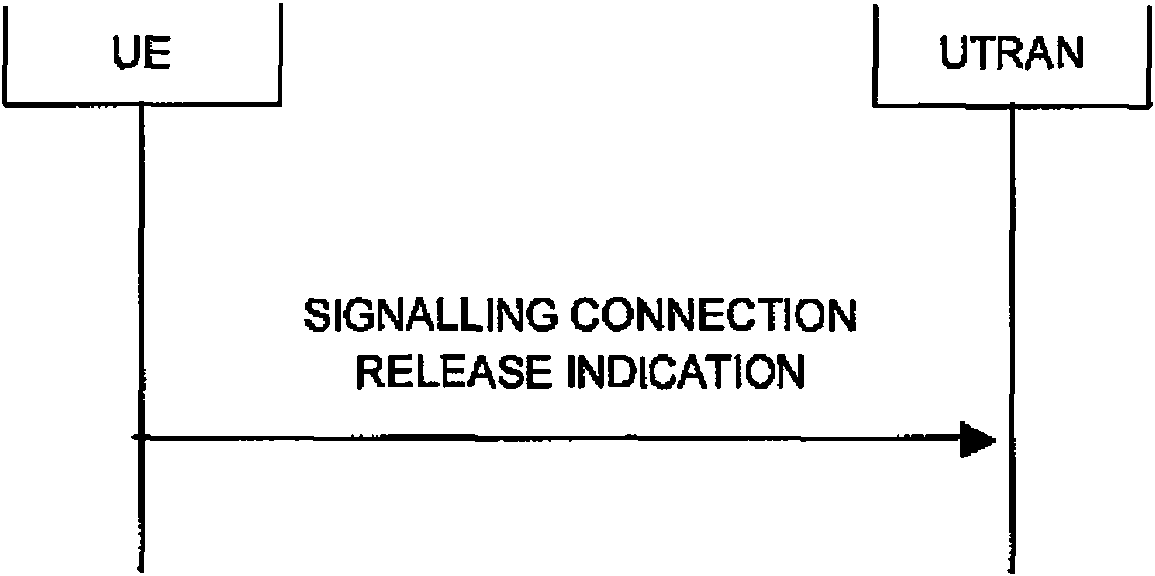
Figura 8.1.14-1: Procedimiento de indicación de liberación de conexión de señalización, caso normal Figure 8.1.14-1: Signaling connection release indication procedure, normal case
8.1.14.1 General8.1.14.1 General
El UE utiliza el procedimiento de indicación de liberación de la conexión de señalización para indicar a la UTRAN que se ha liberado una de sus conexiones de señalización. El procedimiento a su vez puede iniciar el procedimiento de liberación de la conexión de RRC.The UE uses the signaling connection release indication procedure to indicate to the UTRAN that one of its signaling connections has been released. The procedure in turn can initiate the RRC connection release procedure.
8.1.14.2 Iniciación8.1.14.2 Initiation
El UE, al recibir una solicitud para liberar (abortar) la conexión de señalización de las capas superiores para un dominio CN específico: The UE, upon receiving a request to release (abort) the upper layer signaling connection for a specific CN domain:
1> if a signalling connection in tlie variable ESTABLISHEDSIGNALLINGCONNECTIONS for the specific CN domain identiñed with the IE "CN domain identity" exists:1> if a signaling connection in tlie variable ESTABLISHEDSIGNALLINGCONNECTIONS for the specific CN domain identiñed with the IE "CN domain identity" exists:
2> initiate the signalling connection release indication procedure.2> initiate the signaling connection release indication procedure.
1> otherwise:1> otherwise:
2> abort any ongoing establishment o f signalling connection for that spccific CN domain as specified in2> abort any ongoing establishment or f signaling connection for that spccific CN domain as specified in
8.1.3.5a. " ’8.1.3.5a. "’
Al iniciar el procedimiento de indicación de liberación de la conexión de señalización en el estado CELL_PCH o URA_PCH, el UE deberá:When initiating the signaling connection release indication procedure in the CELL_PCH or URA_PCH state, the UE shall:
1> i f variable READY_FOR_COMMON_EDCH is set to TRUE:1> i f variable READY_FOR_COMMON_EDCH is set to TRUE:
2> move to CELL_FACH State; 2> move to CELL_FACH State;
2> restartthe timer T305 using its initial valué if periodical cell update has been configured by T305 in the IE2> restart the timer T305 using its initial value if periodical cell update has been configured by T305 in the IE
"UE Timers and constants in connected mode" set to any other valué than "infinity"."UE Timers and constants in connected mode" set to any other value than "infinity".
1> else:1> else:
2> if variable H RNT1 and variable C_RNTI are set:2> if variable H RNT1 and variable C_RNTI are set:
3> continué with the signalling connection release indication procedure as below.3> continue with the signaling connection release indication procedure as below.
2> else:2> else:
3> perform a cell update procedure, according to subclause 8.3.1, using the cause "uplink data transmission";3> perform a cell update procedure, according to subclause 8.3.1, using the cause "uplink data transmission";
3> when the cell update procedure completed successfully:3> when the cell update procedure completed successfully:
4> continué with the signalling connection release indication procedure as below.4> continue with the signaling connection release indication procedure as below.
El UE deberá:The UE shall:
1> set the IE "CN Domain Identity" to the valué indicated by the upper layers. The valué o f the IE indicates the CN domain whose associated signalling connection the upper layers are indicating to be released;1> set the IE "CN Domain Identity" to the value indicated by the upper layers. The value or f the IE indicates the CN domain whose associated signaling connection the upper layers are indicating to be released;
1> remove the signalling connection with the identity indicated by upper layers ffom the variable ESTABLISHED_SIGN ALLÍN G_CONNECTION S;1> remove the signaling connection with the identity indicated by upper layers ffom the variable ESTABLISHED_SIGN ALLÍN G_CONNECTION S;
1> transmit a SIGNALLING CONNECTION RELEASE INDICATION message on DCCH using AM RLC.1> transmit a SIGNALLING CONNECTION RELEASE INDICATION message on DCCH using AM RLC.
Cuando el RLC confirma la entrega exitosa del mensaje SIGNALLING CONNECTION RELEASE INDICATION, el procedimiento finaliza.When the RLC confirms the successful delivery of the SIGNALLING CONNECTION RELEASE INDICATION message, the procedure ends.
Además, si el valor del temporizador T323 se almacena en el “Temporizadores y Constantes de UE en el Modo Conectado” del IE en la variable TIMERS_AND_CONSTANTS, y si no hay una conexión de dominio CS indicada en la variable ESTABLISHED_SIGNALLING_CONNECTIONS, el UE puede:Also, if the value of the timer T323 is stored in the IE's “UE Timers and Constants in Connected Mode” in the TIMERS_AND_CONSTANTS variable, and if there is no CS domain connection indicated in the ESTABLISHED_SIGNALLING_CONNECTIONS variable, the UE can:
> if the upper layers indícate that there is no more PS data for a prolonged period:> if the upper layers indicate that there is no more PS data for a prolonged period:
2> if timer T323 is not running:2> if timer T323 is not running:
3> if the UE is in CELL DCH state or CELL FACH state; or3> if the UE is in CELL DCH state or CELL FACH state; or
3> if the UE is in CELL PCH state or URA PCH state and "Triggered" in the variable TRIGGERED_SCRI_IN_PCH_STATE is FALSE:3> if the UE is in CELL PCH state or URA PCH state and "Triggered" in the variable TRIGGERED_SCRI_IN_PCH_STATE is FALSE:
4> if the UE is in CELL_PCH or URA_PCH state, set "Triggered" in the variable TRIGGERED_SCRI_IN_PCH_STATE to TRUE;4> if the UE is in CELL_PCH or URA_PCH state, set "Triggered" in the variable TRIGGERED_SCRI_IN_PCH_STATE to TRUE;
4> set the IE "CN Domain Identity" to PS domain;4> set the IE "CN Domain Identity" to PS domain;
4 set the IE "Signalling Connection Release Indication Cause" to "UE Requested PS Data session end";4 set the IE "Signaling Connection Release Indication Cause" to "UE Requested PS Data session end ";
4> transmit a SIGNALLINGCONNECTIONRELEASE INDICATIONmessage onDCCH4> transmit to SIGNALLINGCONNECTIONRELEASE INDICATIONmessage onDCCH
using AM RLC;using AM RLC;
4> start the timer T323.4> start the timer T323.
Cuando la entrega exitosa del mensaje SIGNALLING CONNECTION RELEASE INDICATION ha sido confirmada por RLC, el procedimiento finaliza.When the successful delivery of the SIGNALLING CONNECTION RELEASE INDICATION message has been confirmed by RLC, the procedure ends.
Se impedirá que el UE envíe el mensaje SIGNALLING CONNECTION RELEASE INDICATION con la “Causa de Indicación de Liberación de Conexión de Señalización” del IE establecida en “Fin de Sesión de Datos de PS Solicitados por el UE” mientras el temporizador T323 está en funcionamiento.The UE will be prevented from sending the SIGNALING CONNECTION RELEASE INDICATION message with the IE "Signaling Connection Release Indication Cause" set to "UE Requested PS Data Session End" while timer T323 is running.
Después de enviar el mensaje SIGNALLING CONNECTIO
8.1.14.2a Restablecimiento de RLC o cambio inter-RAT8.1.14.2a RLC reset or inter-RAT change
Si se produce un restablecimiento del lado transmisor de la entidad RLC en la señalización del portador de radio RB2 antes de que el RLC haya confirmado con éxito la entrega del mensaje SIGNALLING CONNeCt ION RELEASE INDICATION, el UE deberá:If a restoration of the transmitting side of the RLC entity occurs in the signaling of the radio bearer RB2 before the RLC has successfully confirmed delivery of the SIGNALING CONN e C t ION RELEASE INDICATION message, the UE shall:
> retransmit the SIGNALLINGCONNECTIONRELEASE INDICATIONmessage onthe uplink DCCH using AM RLC on signalling radio bearer RB2.> retransmit the SIGNALLINGCONNECTIONRELEASE INDICATIONmessage on the uplink DCCH using AM RLC on signaling radio bearer RB2.
Si se produce una transferencia Inter RAT del procedimiento UTRAN antes de que el RLC haya confirmado con éxito la entrega del mensaje SIGNALLING CONNECTION RELEASE INDICATION, el UE deberá:If an Inter RAT transfer of the UTRAN procedure occurs before the RLC has successfully confirmed delivery of the SIGNALLING CONNECTION RELEASE INDICATION message, the UE shall:
1> abort the signalling connection while in the newRAT.1> abort the signaling connection while in the newRAT.
8.1.14.3 Recepción de la SIGNALLING CONNECTION RELEASE INDICATION por parte de la UTRAN8.1.14.3 Reception of the SIGNALING CONNECTION RELEASE INDICATION by the UTRAN
Al recibir un mensaje de SIGNALLING CONNECTION RELEASE INDICATION, si la “Causa de Indicación de Liberación de Conexión de Señalización” del IE no está incluida, la UTRAN solicita la liberación de la conexión de señalización desde las capas superiores. Las capas superiores pueden entonces iniciar la liberación de la conexión de señalización.Upon receiving a SIGNALING CONNECTION RELEASE INDICATION message, if the IE "Signaling Connection Release Indication Cause" is not included, the UTRAN requests the release of the signaling connection from the upper layers. The upper layers can then initiate the release of the signaling connection.
Si la “Causa de indicación de liberación de conexión de señalización” del IE se incluye en el mensaje SIGNALLING CONNECTION RELEASE INDICATION, la UTRAN puede iniciar una transición de estado al consumo de batería eficiente IDLE, CELL_PCH, URA_PCH o CELL_FACH.If the IE "Signaling Connection Release Indication Cause" is included in the SIGNALLING CONNECTION RELEASE INDICATION message, the UTRAN may initiate a state transition to IDLE, CELL_PCH, URA_PCH or CELL_FACH efficient battery consumption.
8.1.14.4 Vencimiento del temporizador T3238.1.14.4 Timer T323 expiration
Cuando expira el temporizador T323:When timer T323 expires:
1> the UE may determine whelhcr any subsequent indications from upper layers ihat there is no more PS data for a prolonged period in whieh case it triggers the transmission o f a single SIGNALLING CONNECTION RELEASE INDICATION message according with clause 8,1.14.2;1> the UE may determine whelhcr any subsequent indications from upper layers ihat there is no more PS data for a prolonged period in whieh case it triggers the transmission or f a single SIGNALLING CONNECTION RELEASE INDICATION message according with clause 8,1.14.2;
1> the procedure ends.1> the procedure ends.
13.4.27x TRIGGERED SCRI IN PCH STATE13.4.27x TRIGGERED SCRI IN PCH STATE
Esta variable contiene información sobre si se ha activado un mensaje SIGNALLING CONNECTION RELEASE INDICATION en los estados CELL PCH o URA PCH. Hay una de esas variables en el UE.This variable contains information on whether a SIGNALING CONNECTION RELEASE INDICATION message has been activated in the CELL PCH or URA PCH states. There is one of those variables in the EU.

Apéndice BAppendix b
8.1.14 Procedimiento de indicación de liberación de conexión de señalización8.1.14 Signaling connection release indication procedure

Figura 8.1.14-1: Procedimiento de indicación de liberación de conexión de señalización, caso normal 8.1.14.1 GeneralFigure 8.1.14-1: Signaling connection release indication procedure, normal case 8.1.14.1 General
El procedimiento de indicación de liberación de conexión de señalización es utilizado por el UE para indicar a la UTRAN que una de sus conexiones de señalización ha sido liberada. El procedimiento a su vez puede iniciar el procedimiento de liberación de la conexión de RRC.The signaling connection release indication procedure is used by the UE to indicate to the UTRAN that one of its signaling connections has been released. The procedure in turn can initiate the RRC connection release procedure.
8.1.14.2 Iniciación8.1.14.2 Initiation
El UE, al recibir una solicitud para liberar (abortar) la conexión de señalización de las capas superiores para un dominio CN específico:The UE, upon receiving a request to release (abort) the upper layer signaling connection for a specific CN domain:
1> i f a signalling connection in the variable ESTABLISHED SIGNALLlNG_CONNECTIONS for the specifíc CN domain identified with the IE "CN domain identity" exists:1> i f a signaling connection in the variable ESTABLISHED SIGNALNG_CONNECTIONS for the specifíc CN domain identified with the IE "CN domain identity" exists:
2> initiate the signalling connection release indication procedure.2> initiate the signaling connection release indication procedure.
1> otherwise:1> otherwise:
2> abort any ongoing establishment o f signalling connection for that specifíc CN domain as specifíed in2> abort any ongoing establishment or f signaling connection for that specifíc CN domain as specifíed in
8.1.3.5a.8.1.3.5a.
Al iniciarse el procedimiento de indicación de liberación de conexión de señalización en estado CELL_PCH o URA_PCH, el UE deberá:Upon initiation of the signaling connection release indication procedure in the CELL_PCH or URA_PCH state, the UE shall:
1> i f variable READY_FOR_COMMON_EDCII is set to TRUE:1> i f variable READY_FOR_COMMON_EDCII is set to TRUE:
2> move to CELL_FACH State;2> move to CELL_FACH State;
2> restart the timer T305 using its initial valué i f periodical cell updatc has been configured by T305 in tire IE2> restart the timer T305 using its initial value i f periodical cell updatc has been configured by T305 in tire IE
"UE Timers and constants in connected mode" set to any olher valué than "infinity"."UE Timers and constants in connected mode" set to any olher value than "infinity".
1> else:1> else:
2> if variable H RNTI and variable C_RNTI are set:2> if variable H RNTI and variable C_RNTI are set:
3> continué with the signalling connection release indication procedure as below.3> continue with the signaling connection release indication procedure as below.
2> clse:2> class:
3> perform a cell update procedure, according to subclause 8.3.1, using the cause "uplink data transmission";3> perform a cell update procedure, according to subclause 8.3.1, using the cause "uplink data transmission";
3> when the cell update procedure completed successfully:3> when the cell update procedure completed successfully:
4> continué with the signalling connection release indication procedure as below.4> continue with the signaling connection release indication procedure as below.
El UE deberá: The UE shall:
1> set the IE "CN Domain Identity’1 to the valué indicated by the upper layers. The valué o f the IE indicates the CN domain whose associated signalling connection the upper layers are indicating to be released;1> set the IE "CN Domain Identity’1 to the value indicated by the upper layers. The value or f the IE indicates the CN domain whose associated signaling connection the upper layers are indicating to be released;
1> remove the signalling connection with the identity indicated by upper layers frora the variable ESTABLISHED_SIGNALLING_CONNECTIONS;1> remove the signaling connection with the identity indicated by upper layers frora the variable ESTABLISHED_SIGNALLING_CONNECTIONS;
1> transmit a SIGNALLING CONNECTION RELEASE INDICATION message on DCCH using AM RLC.1> transmit a SIGNALLING CONNECTION RELEASE INDICATION message on DCCH using AM RLC.
Cuando la entrega exitosa del mensaje SIGNALLING CONNECTION RELEASE INDICATION ha sido confirmada por RLC, el procedimiento finaliza.When the successful delivery of the SIGNALLING CONNECTION RELEASE INDICATION message has been confirmed by RLC, the procedure ends.
Además, si el valor del temporizador T323 se almacena en los “Temporizadores y constantes de UE en modo conectado” del IE en la variable TIMERS_AND_CONSTANTS, y si no hay una conexión de dominio CS indicada en la variable ESTABLISHED_SIGNALLING_CONNECTIONS, el UE puede:Also, if the value of timer T323 is stored in IE's “Connected mode UE timers and constants” in the TIMERS_AND_CONSTANTS variable, and if there is no CS domain connection indicated in the ESTABLISHED_SIGNALLING_CONNECTIONS variable, the UE can:
1> if the upper layers indícate that there is no more PS data for a prolonged period: 2> if timer T323 is not running:1> if the upper layers indicate that there is no more PS data for a prolonged period: 2> if timer T323 is not running:
3> if the 

3> if the 

4> if the 

4> set the IE "CNDomain Identity" to PS domain;4> set the IE "CNDomain Identity" to PS domain;
4> set the IE "Signalling Connection Release Indication Cause" to "UE Requested PS Data4> set the IE "Signaling Connection Release Indication Cause" to "UE Requested PS Data
session end";session end ";
4> transmit a SIGNALLING CONNECTION RELEASE INDICATIONmessage onDCCH4> transmit to SIGNALING CONNECTION RELEASE INDICATIONmessage onDCCH
using AM RLC;using AM RLC;
4> start the timer T323.4> start the timer T323.
Cuando la entrega exitosa del mensaje SIGNALLING CONNECTION RELEASE INDICATION ha sido confirmada por RLC, el procedimiento finaliza.When the successful delivery of the SIGNALLING CONNECTION RELEASE INDICATION message has been confirmed by RLC, the procedure ends.
Se impedirá que el UE envíe el mensaje SIGNALLING CONNECTION RELEASE INDICATION con la “Causa de Indicación de Liberación de Conexión de Señalización” del IE establecido en la “Finalización de Sesión de Datos de PS solicitados por el UE” mientras el temporizador T323 está en funcionamiento.The UE will be prevented from sending the SIGNALING CONNECTION RELEASE INDICATION message with the IE "Signaling Connection Release Indication Cause" set to the "UE Requested PS Data Session Termination" while timer T323 is running .
Si los datos de PS están disponibles para la transmisión o el UE recibe un mensaje de búsqueda que activa el procedimiento de actualización de la celda, entonces el UE pasará V316 a cero.If the PS data is available for transmission or the UE receives a page message that triggers the cell update procedure, then the UE will set V316 to zero.
8.1.14.2a Restablecimiento de RLC o cambio inter-RAT8.1.14.2a RLC reset or inter-RAT change
Si se produce un restablecimiento del lado transmisor de la entidad de RLC en la señalización del portador de radio RB2 antes de que el RLC haya confirmado la entrega exitosa del mensaje SIGNALLING CONNECTION RELEASE INDICATION, el UE deberá:If a restoration of the transmitting side of the RLC entity occurs in the signaling of the radio bearer RB2 before the RLC has confirmed the successful delivery of the SIGNALLING CONNECTION RELEASE INDICATION message, the UE shall:
> retransmit the SIGNALLING CONNECTION RELEASE INDICATIONmessage on theuplink DCCH using AM RLC on signalling radio bearer RB2.> retransmit the SIGNALLING CONNECTION RELEASE INDICATIONmessage on theuplink DCCH using AM RLC on signaling radio bearer RB2.
Si se produce un traspaso inter-RAT desde el procedimiento UTRAN antes de que el RLC haya confirmado con éxito la entrega del mensaje SIGNALLING CONNECTION RELEASE INDICATION, el UE deberá:If an inter-RAT handover occurs from the UTRAN procedure before the RLC has successfully confirmed delivery of the SIGNALLING CONNECTION RELEASE INDICATION message, the UE shall:
1> abort the signalling connection while en el newRAT.1> abort the signaling connection while in the newRAT.
8.1.14.3 Recepción de la SIGNALLING CONNECTION RELEASE INDICATION por parte de la UTRAN8.1.14.3 Reception of the SIGNALING CONNECTION RELEASE INDICATION by the UTRAN
Al recibir un mensaje de SIGNALLING CONNECTION RELEASE INDICATION, si la “Causa de Indicación de Liberación de Conexión de Señalización” del IE no está incluida, la UTRAN solicita la liberación de la conexión de señalización desde las capas superiores. Las capas superiores pueden entonces iniciar la liberación de la conexión de señalización. Upon receiving a SIGNALING CONNECTION RELEASE INDICATION message, if the IE "Signaling Connection Release Indication Cause" is not included, the UTRAN requests the release of the signaling connection from the upper layers. The upper layers can then initiate the release of the signaling connection.
Si la “Causa de Indicación de Liberación de Conexión de Señalización” del IE se incluye en el mensaje SIGNALLING CONNECTION RELEASE INDICATION, la UTRAN puede iniciar una transición de estado al consumo de batería eficiente IDLE, CELL_PCH, URA_PCH o CELL_FACH.If the IE "Signaling Connection Release Indication Cause" is included in the SIGNALLING CONNECTION RELEASE INDICATION message, the UTRAN may initiate a state transition to IDLE, CELL_PCH, URA_PCH, or CELL_FACH efficient battery consumption.
8.1.14.4 Vencimiento del temporizador T3238.1.14.4 Timer T323 expiration
Cuando caduca el temporizador T323:When timer T323 expires:
1> the UE may determine whether any subsequent indications from upper layers that there is no more PS dala for a prolonged period in which case it triggers the transmission o f a single SIGNALLING CONNECTION RELEASE INDICATION message according with clause 8.1.142;1> the UE may determine whether any subsequent indications from upper layers that there is no more PS dala for a prolonged period in which case it triggers the transmission or f a single SIGNALLING CONNECTION RELEASE INDICATION message according with clause 8.1.142;
1> the procedure ends.1> the procedure ends.
8.3 Procedimientos de movilidad de conexión RRC8.3 RRC connection mobility procedures
8.3.1 Procedimientos de actualización de celda y URA8.3.1 Cell and URA update procedures

Figura 8.3.1-2: procedimiento de actualización de celda con actualización de información de movilidad de UTRANFigure 8.3.1-2: Cell update procedure with UTRAN mobility information update
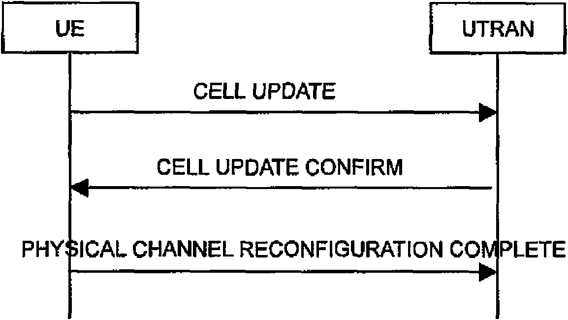
Figura 8.3.1-3: Procedimiento de actualización de Celda con reconfiguración de canal físico Figure 8.3.1-3: Cell update procedure with physical channel reconfiguration

Figura 8.3.1-4: procedimiento de actualización de celda con reconfiguración de canal de transporteFigure 8.3.1-4: Cell update procedure with transport channel reconfiguration

Figura 8.3.1-5: Procedimiento de actualización de celdas con liberación de portador de radioFigure 8.3.1-5: Cell update procedure with radio bearer release

Figura 8.3.1-6: Procedimiento de actualización celular con reconfiguración de portador de radio Figure 8.3.1-6: Cellular update procedure with radio bearer reconfiguration

Figura 8.3.1-6a: Procedimiento de actualización celular con configuración de portador de radioFigure 8.3.1-6a: Cellular update procedure with radio bearer configuration

Figura 8.3.1-8: Procedimiento de actualización de URA, flujo básico Figure 8.3.1-8: URA update procedure, basic flow

Figura 8.3.1-9: Procedimiento de actualización de URA con actualización de información de movilidad de UTRANFigure 8.3.1-9: URA update procedure with UTRAN mobility information update

8.3.1.1 General8.3.1.1 General
Los procedimientos de actualización de celdas y actualización de URA sirven para varios propósitos principales: - notificar a UTRAN después de volver a ingresar al área de servicio en el estado URA_PCH o CELL_PCH;The cell update and URA update procedures serve several main purposes: - notify UTRAN after re-entering the service area in the URA_PCH or CELL_PCH state;
- notificar a UTRAN de un error irrecuperable de RLC [16] en una entidad RLC AM;- notify UTRAN of an unrecoverable RLC error [16] in an RLC AM entity;
- ser utilizado como mecanismo de supervisión en el estado CELL_FACH, CELL_PCH o URA_PCH mediante actualización periódica.- be used as a monitoring mechanism in the CELL_FACH, CELL_PCH or URA_PCH state through periodic update.
Además, el procedimiento de actualización de URA también sirve para el siguiente propósito:Additionally, the URA update procedure also serves the following purpose:
- recuperar una nueva identidad de URA después de la reselección de celda a una celda que no pertenece a la URA actual asignada al UE en estado URA_PCH.- retrieve a new URA identity after cell reselection to a cell that does not belong to the current URA assigned to the UE in URA_PCH state.
Además, el procedimiento de actualización celular también sirve para los siguientes propósitos:Furthermore, the cell update procedure also serves the following purposes:
- actualizar UTRAN con la celda actual en la que el UE está conectando después de la reselección de la celda; - actuar sobre un fallo de enlace de radio en el estado CELL_DCH;- update UTRAN with current cell the UE is connecting to after cell reselection; - act on a radio link failure in the CELL_DCH state;
- actuar sobre el fallo de transmisión del mensaje de UE CAPABILITY INFORMATION;- act on the transmission failure of the UE CAPABILITY INFORMATION message;
- para FDD y 1.28 Mcps TDD, si la variable H_RNTI no está establecida, y para 3.84 Mcps TDD y 7.68 Mcps TDD: cuando se activa en el estado URA_PCH o CELL_PCH, para notificar a UTRAN de una transición al estado CELL_FACH debido a la recepción de Paginación originada por UTRAN o debido a una solicitud para transmitir datos de enlace ascendente;- for FDD and 1.28 Mcps TDD, if the H_RNTI variable is not set, and for 3.84 Mcps TDD and 7.68 Mcps TDD: when activated in the URA_PCH or CELL_PCH state, to notify UTRAN of a transition to the CELL_FACH state due to reception Paging originated by UTRAN or due to a request to transmit uplink data;
- contar el número de UE en URA_PCH, CELL_PCH y CELL_FACH que están interesados en recibir una transmisión MBMS;- counting the number of UEs in URA_PCH, CELL_PCH and CELL_FACH that are interested in receiving an MBMS transmission;
- cuando se activa en el estado URA_PCH, CELL_PCH y CELL_FACH, notificar a UTRAN del interés del UE para recibir un servicio MBMS; - when activated in the URA_PCH, CELL_PCH and CELL_FACH state, notify UTRAN of the UE's interest to receive an MBMS service;
- solicitar la configuración MBMS P-T-P RB por el UE en los estados CELL_PCH, URA_PCH y CELL_FACH.- request the MBMS P-T-P RB configuration by the UE in the CELL_PCH, URA_PCH and CELL_FACH states.
La actualización de URA y los procedimientos de actualización celular pueden:URA update and cellular update procedures can:
1> inelude an updatc o f mobiíity related information in the UE;1> inelude an updatc o f mobiíity related information in the UE;
1> cause a State transition from the CELLJFACH State to the C E L L D C H , C EL L PC H or URA_PCH States or idle mode.1> cause a State transition from the CELLJFACH State to the C E L L D C H, C EL L PC H or URA_PCH States or idle mode.
El procedimiento de actualización celular también puede incluir:The cell update procedure may also include:
- un restablecimiento de las entidades AM RLC;- a re-establishment of the AM RLC entities;
- liberación de portador de radio, reconfiguración de portador de radio, reconfiguración de canal de transporte o reconfiguración de canal físico.- radio bearer release, radio bearer reconfiguration, transport channel reconfiguration or physical channel reconfiguration.
8.3.1.2 Iniciación8.3.1.2 Initiation
Un UE iniciará el procedimiento de actualización celular en los siguientes casos:A UE will initiate the cellular update procedure in the following cases:
1> Uplink data transmission:1> Uplink data transmission:
2> for FDD and 1.28 Mcps TDD, if the variable H_RNTI is not set, and for 3.84 Mcps TDD and 7.68 Mcps TDD:2> for FDD and 1.28 Mcps TDD, if the variable H_RNTI is not set, and for 3.84 Mcps TDD and 7.68 Mcps TDD:
3> if the UE is in URA PCH or CELL PCH State; and3> if the UE is in URA PCH or CELL PCH State; and
3> i f timer T320 is not running:3> i f timer T320 is not running:
4> if the UE has uplink RLC data PDU or uplink RLC control PDU on RB1 or upwards to transmit: 5> perform cell update using the cause "uplink data tr ansmission''.4> if the UE has uplink RLC data PDU or uplink RLC control PDU on RB1 or upwards to transmit: 5> perform cell update using the cause "uplink data tr ansmission ''.
3> else:3> else:
4> i f the variable ESTABLISHMENT.CAUSE is set:4> i f the variable ESTABLISHMENT.CAUSE is set:
5> perform cell update using the cause "uplink data transmission”.5> perform cell update using the cause "uplink data transmission".
1> Paging response:1> Paging response:
2> if the criteria for performing cell update with the cause specifíed above in the current subclause are not met;2> if the criteria for performing cell update with the cause specified above in the current subclause are not met;
and and
2> if the UF, in IJRA_PCH or CELL_PCH State, receives a PAGINO TYPE 1 message fulfilling the condítions for initiating a cell update procedure spccified in subclause 8.1.2.3:2> if the UF, in IJRA_PCH or CELL_PCH State, receives a PAGINO TYPE 1 message fulfilling the conditions for initiating a cell update procedure spccified in subclause 8.1.2.3:
3> perform cell update using the cause "paging response'1.3> perform cell update using the cause "paging response'1.
> Radio link failure:> Radio link failure:
2> i f none o f the criteria for performing cell update with the causes specified above in the current subclause is met:2> i f none o f the criteria for performing cell update with the causes specified above in the current subclause is met:
3> i f the UE is in CELL_DCH state and the criteria for radio link failure are met as specified in subclause 8.5.6; or3> i f the UE is in CELL_DCH state and the criteria for radio link failure are met as specified in subclause 8.5.6; or
3> if the transmission o f the UE CAPABILITY INFORMATION message fails as specified in subclause 8.1.6.6: 3> if the transmission of the UE CAPABILITY INFORMATION message fails as specified in subclause 8 . 1 . 6 . 6 :
4> perform cell update using the cause "radio link failure".4> perform cell update using the cause "radio link failure".
> MBMS ptp RB requcst:> MBMS ptp RB requcst:
2> i f none o f the criteria for performing cell update with the causes specified above in the current subclause is met; and2> i f none o f the criteria for performing cell update with the causes specified above in the current subclause is met; and
2> if the UE is in URA_PCH, Cell_PCH or Cell_FACH State; and2> if the UE is in URA_PCH, Cell_PCH or Cell_FACH State; and
2> i f limer T320 is not running; and2> i f limer T320 is not running; and
2> i f the UE should perform cell update for MBMS ptp radio bearer request as specified in subclause 8.6.9.6:2> i f the UE should perform cell update for MBMS ptp radio bearer request as specified in subclause 8.6.9.6:
3> perform cell update using the cause "MBMS ptp RB request".3> perform cell update using the cause "MBMS ptp RB request".
> Re-entering scrvice area:> Re-entering scrvice area:
2> if none o f the criteria for performing cell update with the causes specified above in lhc current subclause is met; and2> if none or f the criteria for performing cell update with the causes specified above in lhc current subclause is met; and
2> i f lhc UE is in CELL_FACH or CELL_PCH state; and2> i f lhc UE is in CELL_FACH or CELL_PCH state; and
2> i f the UE has been out o f service area and rc-cnters Service area before T307 or T 317 expires:2> i f the UE has been out o f service area and rc-cnters Service area before T307 or T 317 expires:
3> perform cell update using the cause "re-entering Service area".3> perform cell update using the cause "re-entering Service area".
> RLC unrecoverable error:> RLC unrecoverable error:
2> i f none o f the criteria for performing cell update with the causes specified above in the current subclause is met; and2> i f none o f the criteria for performing cell update with the causes specified above in the current subclause is met; and
2> if the UE deteets RLC unrecoverable error [16] in an AM RLC entity:2> if the UE deteets RLC unrecoverable error [16] in an AM RLC entity:
3> perform cell update using the cause "RLC unrecoverable error",3> perform cell update using the cause "RLC unrecoverable error",
> Cell reselection:> Cell reselection:
2> i f none o f the criteria for performing cell update with the causes specified above in the current subclause is met:2> i f none o f the criteria for performing cell update with the causes specified above in the current subclause is met:
3> if the UE is in CELL_FACI I or CELL PCH state and the UE performs cell re-selection; or3> if the UE is in CELL_FACI I or CELL PCH state and the UE performs cell re-selection; or
3> i f the UE is in CELL_FACH state and the variable C_RNTI is empty:3> i f the UE is in CELL_FACH state and the variable C_RNTI is empty:
4> perform cell update using the cause "cell reselection".4> perform cell update using the cause "cell reselection".
> Periodical cell update: > Periodical cell update:
2> if noce o f the criteria for perfonning cell update with the causes specifíed above ín the currcnt subclause is met; and2> if noce o f the criteria for perfonning cell update with the causes specified above in the currcnt subclause is met; and
2> if the UE is in CELL_FACH or CELL PCII State; and2> if the UE is in CELL_FACH or CELL PCII State; and
2> if tlie timer T305 expires; and2> if tlie timer T305 expires; and
2> i f the criteria for "in Service area" as specifíed in subclause 8.5.5.2 are fulfillcd; and2> i f the criteria for "in Service area" as specified in subclause 8.5.5.2 are fulfillcd; and
2> if periodic updating has been configurad by T305 in the IE "UE Timers and constants in connected raode" set to any other valué than "infinity":2> if periodic updating has been configured by T305 in the IE "UE Timers and constants in connected raode" set to any other value than "infinity":
3> for FDD:3> for FDD:
4> if the variable C O M M O N _E _D C H .T R A N SM ISIO N is set lo FALSE:4> if the variable C O M M O N _E _D C H .T R A N SM ISIO N is set lo FALSE:
5> perform cell update using the cause "periodieal cell update".5> perform cell update using the cause "periodieal cell update".
4> else:4> else:
5> restart the timer T305;5> restart the timer T305;
5> and end the procedure.5> and end the procedure.
3> for 1.28 Mcps TDD and 3.84/7.68 Mcps TDD:3> for 1.28 Mcps TDD and 3.84 / 7.68 Mcps TDD:
4> perform cell update using the cause "periodieal cell update".4> perform cell update using the cause "periodieal cell update".
1> MBMS reception;1> MBMS reception;
2> if none o f the criteria for performing cell update with the causes specifíed above in the current subclause is met; and2> if none or f the criteria for performing cell update with the causes specified above in the current subclause is met; and
2> if the UE is in U R A P C II, Cell_PCH or Ccll_FACH state; and2> if the UE is in U R A P C II, Cell_PCH or Ccll_FACH state; and
2> if the UE should perform cell update for MBMS counting as specifíed in subclause 8.7.4:2> if the UE should perform cell update for MBMS counting as specified in subclause 8.7.4:
3> perform cell update using the cause "MBMS reception".3> perform cell update using the cause "MBMS reception".
Un UE en estado URA_PCH iniciará el procedimiento de actualización de URA en los siguientes casos:A UE in URA_PCH state will initiate the URA update procedure in the following cases:
1> URA reselection:1> URA reselection:
2> if the UE deteets that the current URA assigned to the UE, stored in the variable URAIDEN TITY , is not present in the list o f URA identities in system information block type 2; or2> if the UE deteets that the current URA assigned to the UE, stored in the variable URAIDEN TITY, is not present in the list or f URA identities in system information block type 2; or
2> if the list o f URA identities in system information block type 2 is empty; or2> if the list or f URA identities in system information block type 2 is empty; or
2> i f the system information block type 2 can not be found:2> i f the system information block type 2 can not be found:
3> perform URA update using the cause "change o f URA".3> perform URA update using the cause "change o f URA".
i> Periodic URA update:i> Periodic URA update:
2> if the criteria for performing URA update with the causes as specifíed above in the current subclause are not met:2> if the criteria for performing URA update with the causes as specified above in the current subclause are not met:
3> i f the timer T305 expires and if periodic updating has been confígured by T305 in the IE "UE Timers and constants in connected mode" set to any other valué than "infinity"; or3> i f the timer T305 expires and if periodic updating has been configured by T305 in the IE "UE Timers and constants in connected mode" set to any other value than "infinity"; or
3> i f the condilions for initiating an URA update procedure specifíed in subclause 8.1.1.6.5 are fullfilled: 4> perform URA update using the cause "periodic URA update".3> i f the condilions for initiating an URA update procedure specified in subclause 8.1.1.6.5 are fullfilled: 4> perform URA update using the cause "periodic URA update".
Al iniciar el procedimiento de actualización de celda o actualización de URA, el UE deberá:When initiating the cell update or URA update procedure, the UE shall:
1> if the UE has uplink RLC data PDU or uplink RLC control PDU on RB3 or unvvards to transmití or 1> if the UE has uplink RLC data PDU or uplink RLC control PDU on RB3 or unvvards to transmití or > if tlie UE received a PAGINO TYPE 1 messaue fulfilling the conditions for initiating a cell updalc procedure snecified in subclause 8,1.2.3:> if tlie UE received a PAGINO TYPE 1 month that fulfilling the conditions for initiating a cell updalc procedure snecified in subclause 8,1.2.3:
2> set the counter V 316 to zero.2> set the counter V 316 to zero.
> if timer T320 is running:> if timer T320 is running:
2> stop timer T320;2> stop timer T320;
2 > ifthe UE has uplink RLC data PDU or uplink RLC control PDU on RD1 or upwards to transmit: 2 > if the UE has uplink RLC data PDU or uplink RLC control PDU on RD1 or upwards to transmit:
3> perform cell update using the cause "uplink data transmission".3> perform cell update using the cause "uplink data transmission".
2> else:2> else:
3> ifthe cell update procedure is not triggered due to Paging response or Radio link failure; and3> if the cell update procedure is not triggered due to Paging response or Radio link failure; and
3> if the UE should perform cell update for MBMS ptp radio bearer request as specitíed in subclause 8.6.9.6: 4> perform cell update using the cause "MBMS ptp RB request".3> if the UE should perform cell update for MBMS ptp radio bearer request as specified in subclause 8.6.9.6: 4> perform cell update using the cause "MBMS ptp RB request".
> stop timer T319 if it is running;> stop timer T319 if it is running;
> stop timer T305;> stop timer T305;
> for FDD and 1.28 Mcps TDD:> for FDD and 1.28 Mcps TDD:
2> if the UE is in CELL FACH State; and2> if the UE is in CELL FACH State; and
2> ifthe IF. "HS-DSCH common system information" is included in System Information Blocktype 5 or System Information Block type 5bis; and2> if the IF. "HS-DSCH common system information" is included in System Information Blocktype 5 or System Information Block type 5bis; and
2> for 1.28 Mcps TDD, if IE "Common E-DCH system info" in System Information Block type 5; and 2> if the UE does support HS-DSCH reception in CELL_FACH State:2> for 1.28 Mcps TDD, if IE "Common E-DCH system info" in System Information Block type 5; and 2> if the UE does support HS-DSCH reception in CELL_FACH State:
3> if variable H_RNTI is not set or variable C RNT1 is not set:3> if variable H_RNTI is not set or variable C RNT1 is not set:
4> clear variable H_RNTI;4> clear variable H_RNTI;
4> clear variable C_RNTI;4> clear variable C_RNTI;
4> clear any stored IEs "HARQ info";4> clear any stored IEs "HARQ info";
4> set variable HS_DSCH_RECEPTION_OF_CCCH_ENABLED to TRUE;4> set variable HS_DSCH_RECEPTION_OF_CCCH_ENABLED to TRUE;
4> and start receiving the HS-DSCII transport channels mapped physical channel(s) o f type FIS-SCCH and HS-PDSCH, by using parameters given by the IE(s) "IIS-DSCH common system information" according to the procedure in subclause 8.5.37.4> and start receiving the HS-DSCII transport channels mapped physical channel (s) of type FIS-SCCH and HS-PDSCH, by using parameters given by the IE (s) "IIS-DSCH common system information" according to the procedure in subclause 8.5.37.
3> else:3> else:
4> receive the HS-DSCH transport channels mapped physical channel(s) o f type IIS-SCCH and HS-PDSCH, by using parameters given by the IE(s) "HS-DSCH common system information" according tothe procedure in subclause 8.5.36;4> receive the HS-DSCH transport channels mapped physical channel (s) of type IIS-SCCH and HS-PDSCH, by using parameters given by the IE (s) "HS-DSCH common system information" according to the procedure in subclause 8.5. 36;
4> determine the valué for the IISPA_RNTT_STORED_CELL PCII variable and take the corresponding actions as described in subclause 8.5.56;4> determine the value for the IISPA_RNTT_STORED_CELL PCII variable and take the corresponding actions as described in subclause 8.5.56;
4> determine the valué for the READY_FOR_COMMON_EDCH variable and take the corresponding actions as described in subclause 8.5.47;4> determine the value for the READY_FOR_COMMON_EDCH variable and take the corresponding actions as described in subclause 8.5.47;
4> determ ine the va lu é for the C O M M O N _E _D C H _T R A N SM ISS IO N variable and take the corresponding actions as described in subclause 8.5.46; 4> determine the value for the C O M M O N _E _D C H _T R A N SM ISS IO N variable and take the corresponding actions as described in subclause 8.5.46;
4> ¡f variable READY_FOR COMMON_EDCH is set to TRÜE:4> ¡f variable READY_FOR COMMON_EDCH is set to TRÜE:
5> configure the Enhanced Uplink in CELLFACH State and Idle modc as specified in subclause 8.5.45 for FDD and 8.5.45a for 1.28 Meps TDD.5> configure the Enhanced Uplink in CELLFACH State and Idle modc as specified in subclause 8.5.45 for FDD and 8.5.45a for 1.28 Meps TDD.
> if the UE is in CELL_DCH State: > if the UE is in CELL_DCH State:
2> in the variable RB TIMHR INDICATOR, set the IE "T314 expired" and the IE "T315 expired" to FALSE; 2> if the stored valúes o f the timer T314 and timer T 315 are both equal to zero; or2> in the variable RB TIMHR INDICATOR, set the IE "T314 expired" and the IE "T315 expired" to FALSE; 2> if the stored values o f the timer T314 and timer T 315 are both equal to zero; or
2> if tile stored valué o f the timer T 314 is equal to zero and there are no radio bearers associated with any radio access bearers for which in the variable ESTABLISHEDJRABS the valué o f the IE "Re-establishment timer" is set to "useT315" and signalling connection exists only to the CS domain:2> if tile stored value of the timer T 314 is equal to zero and there are no radio bearers associated with any radio access bearers for which in the variable ESTABLISHEDJRABS the value of the IE "Re-establishment timer" is set to "useT315" and signaling connection exists only to the CS domain:
3> release all its radio resources;3> release all its radio resources;
3> indícate release (abort) o f the established signalling connections (as stored in the variable ESTABLISHED_SIGNALL1NG CONNECTIONS) and established radio access bearers (as stored in the variable ESTABLISHEDRABS) to uppcr layers;3> indicate release (abort) or f the established signaling connections (as stored in the variable ESTABLISHED_SIGNALL1NG CONNECTIONS) and established radio access bearers (as stored in the variable ESTABLISHEDRABS) to uppcr layers;
3> clearthe variable ESTABLISHEDSIGNALLINGCONNECTIONS;3> clearthe variable ESTABLISHEDSIGNALLINGCONNECTIONS;
3> clear the variable ESTABLISHED_RABS;3> clear the variable ESTABLISHED_RABS;
3> enter idle mode;3> enter idle mode;
3> perform other actions when entering idle mode from connected modc as specified in subclause 8.5.2; 3> and the proccdure ends.3> perform other actions when entering idle mode from connected modc as specified in subclause 8.5.2; 3> and the proccdure ends.
2> if the stored valué o f the timer T 314 is equal to zero:2> if the stored value or f the timer T 314 is equal to zero:
3> release all radio bearers, associated with any radio access bearers for which in the variable ESTABLISHED RABS the valué ofthe IE "Re-establishment timer" is setto "useT314";3> release all radio bearers, associated with any radio access bearers for which in the variable ESTABLISHED RABS the value of the IE "Re-establishment timer" is setto "useT314";
3> in the variable RB TIMER_1NDÍCAT0R set the IE "T314 expired" to TRUE;3> in the variable RB TIMER_1NDÍCAT0R set the IE "T314 expired" to TRUE;
3> if all radio access bearers associated with a CN domain are released:3> if all radio access bearers associated with a CN domain are released:
4> release the signalling connection for that CN domain;4> release the signaling connection for that CN domain;
4> remove the signalling connection for that CN domain from the variable ESTABLISHED_SIGNALLING_CONNBCTIONS;4> remove the signaling connection for that CN domain from the variable ESTABLISHED_SIGNALLING_CONNBCTIONS;
4> indícate release (abort) o f the signalling connection to upper layers;4> indicate release (abort) or f the signaling connection to upper layers;
2> if the stored valué o f the timer T 315 is equal to zero:2> if the stored value or f the timer T 315 is equal to zero:
3> release all radio bearers associated with any radio access bearers for which in the variable ESTABLISHED RABS the valué ofthe IE "Re-establishmenttimer" is setto "useT315";3> release all radio bearers associated with any radio access bearers for which in the variable ESTABLISHED RABS the value of the IE "Re-establishmenttimer" is setto "useT315";
3> in the variable RB_TIMER_INDICATOR set the IE "T315 expired" to TRUE.3> in the variable RB_TIMER_INDICATOR set the IE "T315 expired" to TRUE.
3> if all radio access bearers associated with a CN domain are released:3> if all radio access bearers associated with a CN domain are released:
4> release the signalling connection for that CN domain;4> release the signaling connection for that CN domain;
4> remove the signalling connection for that CN domain from the variable F.STABLISHED_SIGNALLING_CONNECTIONS;4> remove the signaling connection for that CN domain from the variable F.STABLISHED_SIGNALLING_CONNECTIONS;
4> indícate release (abort) o f the signalling connection to upper layers;4> indicate release (abort) or f the signaling connection to upper layers;
2> if the stored valué o f the timer T 314 is greater than zero: 2> if the stored value or f the timer T 314 is greater than zero:
3> i f there are radio bearers associated witii any radio access bearers for which in the variable ESTABL1SHED_RABS the valué o f the IE "Re-establishment timer1' is set to "useT314":3> i f there are radio bearers associated witii any radio access bearers for which in the variable ESTABL1SHED_RABS the value or f the IE "Re-establishment timer1 'is set to" useT314 ":
4> start timer T 314.4> start timer T 314.
3> i f there are no radio bearers associated with any radio access bearers for which in the variable ESTABLISHED RABS the valué o f the IE "Re-cstablishment timer" is sel to "useT314" or "useT315" and the signalling connection exists to the CS domain:3> if there are no radio bearers associated with any radio access bearers for which in the variable ESTABLISHED RABS the value of the IE "Re-cstablishment timer" is sel to "useT314" or "useT315" and the signaling connection exists to the CS domain:
4> start timer T 314.4> start timer T 314.
> if the stored valué o f the timer T 315 is greater than zero:> if the stored value or f the timer T 315 is greater than zero:
3> i f there are radio bearers associated with any radio access bearers for which in the variable ESTABLISHED_RABS the valué o f the IE "Re-establishment timer" is set to "useT315"; or3> i f there are radio bearers associated with any radio access bearers for which in the variable ESTABLISHED_RABS the value o f the IE "Re-establishment timer" is set to "useT315"; or
3> if the signalling connection exists to the PS domain:3> if the signaling connection exists to the PS domain:
4> start timer T 315.4> start timer T 315.
> for the released radio bearer(s):> for the released radio bearer (s):
3> delete the information about the radio bearer from the variable ESTABI,1SHED_RABS;3> delete the information about the radio bearer from the variable ESTABI, 1SHED_RABS;
3> when all radio bearers belonging to the same radio access bearer have been released:3> when all radio bearers belonging to the same radio access bearer have been released:
4> indícate local end release o f the radio access bearer to upper layers using the CN domain identity together with the RAB identity stored in the variable ESTABLISHED RABS;4> indicate local end release or f the radio access bearer to upper layers using the CN domain identity together with the RAB identity stored in the variable ESTABLISHED RABS;
4> delete all information about the radio access bearer from the variable ESTABLISHED_RABS. > if the variable EJDC H TR AN SM ISSIO N is set to TRUE:4> delete all information about the radio access bearer from the variable ESTABLISHED_RABS. > if the variable EJDC H TR AN SM ISSIO N is set to TRUE:
3> set tire variable E_DCH_TRANSMISSION to FALSE;3> set tire variable E_DCH_TRANSMISSION to FALSE;
3> stop any E-AGCH and E-HICH reception procedures;3> stop any E-AGCH and E-HICH reception procedures;
3> for FDD, stop any E-RGCH reception procedures.3> for FDD, stop any E-RGCH reception procedures.
3> for FDD, stop any E-DPCCH and E-DPDCH transmission procedures.3> for FDD, stop any E-DPCCH and E-DPDCH transmission procedures.
3> for 1.28 Mcps TDD, stop any E-PUCH transmission procedure.3> for 1.28 Mcps TDD, stop any E-PUCH transmission procedure.
3> clcar the variable E RNTI;3> click the variable E RNTI;
3> act as i f the IE "MAC-es/e reset indicator" was received and set to TRUE;3> act as i f the IE "MAC-es / e reset indicator" was received and set to TRUE;
3> release all E-DCH HARQ resources;3> release all E-DCH HARQ resources;
3> no longer consider any radio link to be the serving E-DCH radio link.3> no longer consider any radio link to be the serving E-DCH radio link.
> move to CELL_FACH State;> move to CELL_FACH State;
> select a suitable UTRA cell on the current ffequeney accordmg to [4];> select a suitable UTRA cell on the current ffequeney accordmg to [4];
> clear variable E_RNTI and:> clear variable E_RNTI and:
3> determine the valué for the HSPA_RNTI_STORED_CELL_PCH variable and take the coiresponding aetions as described in subclause 8.5.56;3> determine the value for the HSPA_RNTI_STORED_CELL_PCH variable and take the coiresponding aetions as described in subclause 8.5.56;
3> determine the valué for the READY_FOR_COMMOM_EDCH variable and take the corresponding aetions as described in subclause 8.5.47;3> determine the value for the READY_FOR_COMMOM_EDCH variable and take the corresponding actions as described in subclause 8.5.47;
3 > determ ine the v a lú e for th e C O M M O N E _ D C H _ T R A N S M IS S 1 O N variab le and take the corresp on d in g aetion s as descr ib ed in su b c la u se 8.5.46. 3> determine the v a lú e for th e C O M M O N E _ D C H _ T R A N S M IS S 1 O N variab le and take the corresp on d in g aetion s as described in su b c la u se 8.5.46.
2> for 3.84 Mcps TDD and 7.68Mcps TDD; or2> for 3.84 Mcps TDD and 7.68Mcps TDD; or
2> for FDD and 1.28 Mcps TDD, if'the UE does not support HS-DSCH reception in CELLJFACH State; or 2> i f the IE "HS-DSCH common system information" is not included in System Information Block type 5 or System Information Block type 5bis; or2> for FDD and 1.28 Mcps TDD, if the UE does not support HS-DSCH reception in CELLJFACH State; or 2> i f the IE "HS-DSCH common system information" is not included in System Information Block type 5 or System Information Block type 5bis; or
2> for 1.28 Mcps TDD, if the IE "Common E-DCH system info" is not included in System Information Block type 5:2> for 1.28 Mcps TDD, if the IE "Common E-DCH system info" is not included in System Information Block type 5:
3> select PRACH accordingto subclause 8.5.17;3> select PRACH according to subclause 8.5.17;
3> select Secondary CCPCH according to subclause 8.5.19;3> select Secondary CCPCH according to subclause 8.5.19;
3> use the transport format set given in system information as specified in subclause 8.6.5.1;3> use the transport format set given in system information as specified in subclause 8.6.5.1;
3> take the actions related to the HS_DSCH RECEPTION_G ENERAL variable as described in subclause 8.5.37a.3> take the actions related to the HS_DSCH RECEPTION_G ENERAL variable as described in subclause 8.5.37a.
2> else:2> else:
3> if variable READY_FOR_COMMON_EDCH is set to TRUE:3> if variable READY_FOR_COMMON_EDCH is set to TRUE:
4> configure the Enhanced Uplink in CELL_FACH State and Idle mode as specified in subclause 8.5.45.4> configure the Enhanced Uplink in CELL_FACH State and Idle mode as specified in subclause 8.5.45.
3> else:3> else:
4> select PRACH according to subclause 8,5.17 and;4> select PRACH according to subclause 8,5.17 and;
5> use for the PRACH the transport format set given in system information as specified in subclause 8.6.5,1. "5> use for the PRACH the transport format set given in system information as specified in subclause 8.6.5,1. "
3> clear variable H_RNTI;3> clear variable H_RNTI;
3> clear any stored lEs "HARQ info";3> clear any stored lEs "HARQ info";
3> reset the MAC-ehs entity [15];3> reset the MAC-ehs entity [15];
3> set variable IIS_DSCII_RECEPTION_ OF_ CCCH_ENABLED to TRUE;3> set variable IIS_DSCII_RECEPTION_ OF_ CCCH_ENABLED to TRUE;
3> and start receiving the HS-DSCH according to the procedure in subclause 8.5.37.3> and start receiving the HS-DSCH according to the procedure in subclause 8.5.37.
2> set the variable ORDEREDRECONFIGURATION to FALSE.2> set the variable ORDEREDRECONFIGURATION to FALSE.
> set the variables PROTOCOL_ERROR INDICATOR, FAILURE_INDICATOR, UNSUPPORTED_CONFIGURATION and INVALID_CONFIGURATION to FALSE;> set the variables PROTOCOL_ERROR INDICATOR, FAILURE_INDICATOR, UNSUPPORTED_CONFIGURATION and INVALID_CONFIGURATION to FALSE;
> set the variable CELL_UPDATE_STARTED to TRUE;> set the variable CELL_UPDATE_STARTED to TRUE;
> if any IEs releated to HS-DSCHare stored in the UE:> if any IEs releated to HS-DSCHare stored in the UE:
2> clear any stored IE "Downlink HS-PDSCH information";2> clear any stored IE "Downlink HS-PDSCH information";
2> clear any stored IE "Downlink Secondaiy Cell Info FDD";2> clear any stored IE "Downlink Secondaiy Cell Info FDD";
2> clear all the entries from the variable TARGET_CELL_PRECONFIGURATION;2> clear all the entries from the variable TARGET_CELL_PRECONFIGURATION;
2> for 1.28Mcps TDD, clear the IE "HS-PDSCH Midamble Configuradon" and the IE "HS-SCCII Set Configuration" in the IE "DL Multi Carrier Information";2> for 1.28Mcps TDD, clear the IE "HS-PDSCH Midamble Configuradon" and the IE "HS-SCCII Set Configuration" in the IE "DL Multi Carrier Information";
2> determine the valué for the HS _DSCH_RECEPTION variable and take the corresponding actions as described in subclause 8.5.25;2> determine the value for the HS _DSCH_RECEPTION variable and take the corresponding actions as described in subclause 8.5.25;
2 > determ ine the va lu é for the S E C O N D A R Y C E L L _H S _D SC H _R E C E P T IO N variab le and take the correspon d ing actions as describ ed in su bclau se 8.5.51. 2> determine the va lu é for the S E C O N D A R Y C E L L _H S _D SC H _R E C E P T IO N variab le and take the corresponding actions as described in su bclau se 8.5.51.
> if any IEs related to E-DCH are stored iii the UE:> if any IEs related to E-DCH are stored iii the UE:
2> clear any stored IE "E-DCH info";2> clear any stored IE "E-DCH info";
2> determine the valué for the E D C H TR A N SM ISSIO N variable and take the corresponding actions as described in subclause 8.5.28.2> determine the value for the E D C H TR A N SM ISSIO N variable and take the corresponding actions as described in subclause 8.5.28.
> if any o f the IEs "DTX-DRX timing information" or "DTX-DRX information'1 are stored in the UE:> if any or f the IEs "DTX-DRX timing information" or "DTX-DRX information'1 are stored in the UE:
2> determine the valúe for the DTX_DRX_STATUS variable and take the corresponding actions as described in subclause 8.5.34.2> determine the value for the DTX_DRX_STATUS variable and take the corresponding actions as described in subclause 8.5.34.
> if the IE "HS-SCCII less information" is stored in the UE:> if the IE "HS-SCCII less information" is stored in the UE:
2> determine the valué for the HS_SCCH_LESS_STATUS variable and take the corresponding actions as described in subclause 8.5.35.2> determine the value for the HS_SCCH_LESS_STATUS variable and take the corresponding actions as described in subclause 8.5.35.
> if any IEs related to MIMO are stored in the UE:> if any IEs related to MIMO are stored in the UE:
2> determine the valué for the MIMOJSTATUS variable and take the corresponding actions as described in subclause 8,5.33.2> determine the value for the MIMOJSTATUS variable and take the corresponding actions as described in subclause 8,5.33.
> for 1.28 Mcps TDD, if the IEs "Control Channel DRX Information" is stored in the UE:> for 1.28 Mcps TDD, if the IEs "Control Channel DRX Information" is stored in the UE:
2> determine the valué for the CONTROL_CHANNEL_DRX_STATUS variable and take the corresponding actions as described in subclause 8.5.53.2> determine the value for the CONTROL_CHANNEL_DRX_STATUS variable and take the corresponding actions as described in subclause 8.5.53.
> for 1.28 Mcps TDD, if the IE "SPS information" is stored in the UE:> for 1.28 Mcps TDD, if the IE "SPS information" is stored in the UE:
2> determine the valué for the E_DCH_SPS_STATUS variable and take the corresponding actions as described in subclause 8.5.54;2> determine the value for the E_DCH_SPS_STATUS variable and take the corresponding actions as described in subclause 8.5.54;
2> determine the valué for the HS_DSCH_SPS_ STATUS variable and take the corresponding actions as described in subclause 8.5.55.2> determine the value for the HS_DSCH_SPS_ STATUS variable and take the corresponding actions as described in subclause 8.5.55.
> if the UE is not already in CELL FACH State:> if the UE is not already in CELL FACH State:
2> move to CELL_FACH State;2> move to CELL_FACH State;
2> determine the valué for the HSPA_RNTI_STORED_CELL_PCH variable and take the corresponding actions as described in subclause 8.5.56;2> determine the value for the HSPA_RNTI_STORED_CELL_PCH variable and take the corresponding actions as described in subclause 8.5.56;
2> determine the valué for the READY_FOR_COMMON_EDCH variable and take the corresponding actions as described in subclause 8.5.47; ' 2> detennine the valué for the COMMON_E_DCH_TRANSMISSION variable and take the corresponding actions as described in subclause 8.5.46;2> determine the value for the READY_FOR_COMMON_EDCH variable and take the corresponding actions as described in subclause 8.5.47; '2> stop the value for the COMMON_E_DCH_TRANSMISSION variable and take the corresponding actions as described in subclause 8.5.46;
2> for 3.84 Mcps TDD and 7.68 Mcps TDD; or2> for 3.84 Mcps TDD and 7.68 Mcps TDD; or
2> for FDD and 1.28 Mcps TDD, if the UE does not support HS-DSCH reception in CELL_FACH State; or 2> i f the IE "HS-DSCH common System information" is not included in System Information Block type 5 or System Information Block type 5bis; or2> for FDD and 1.28 Mcps TDD, if the UE does not support HS-DSCH reception in CELL_FACH State; or 2> i f the IE "HS-DSCH common System information" is not included in System Information Block type 5 or System Information Block type 5bis; or
2> for 1.28 Mcps TDD, if the IE "Common E-DCH system info” is not included in System Information Block type 5:2> for 1.28 Mcps TDD, if the IE "Common E-DCH system info” is not included in System Information Block type 5:
3> select PRACH according to subclause 8.5.17;3> select PRACH according to subclause 8.5.17;
3> select Secondary CCPCH according to subclause 8.5.19;3> select Secondary CCPCH according to subclause 8.5.19;
3 > use the transport form at set g iv en in system inform ation as sp ec iñ ed in subclause 8.6.5.1 ; 3> use the transport form at set g iv in in system inform ation as sp ec iñ ed in subclause 8.6.5.1;
3> take the actions related to the HS_DSCH_RECEPTION_GENERAL variable as described in subclause 8.5.37a.3> take the actions related to the HS_DSCH_RECEPTION_GENERAL variable as described in subclause 8.5.37a.
2> else:2> else:
3> if variable READY_FOR_COMMON_EDCH is set to TRUE:3> if variable READY_FOR_COMMON_EDCH is set to TRUE:
4> configure the Enhanced Uplink in CELL FACII State and Idle mode as specified in subclause 8.5.45. 4> configure the Enhanced Uplink in CELL FACII State and Idle mode as specified in subclause 8.5.45.
3> else:3> else:
4> select PRACH according to subclause 8.5.17 and:4> select PRACH according to subclause 8.5.17 and:
5> use for the PRACH the transport format sel given in system informalion as specified in subclause 8.6.5.1. ^ ’5> use for the PRACH the transport format sel given in system informalion as specified in subclause 8.6.5.1. ^ ’
3> if variable H_RNTI is not set or variable C_RNTI is not set:3> if variable H_RNTI is not set or variable C_RNTI is not set:
4> clear variable C RNTI;4> clear variable C RNTI;
4> clear variable H_RNTI;4> clear variable H_RNTI;
4> clear any stored IEs "HARQ info";4> clear any stored IEs "HARQ info";
4> set variable HS_DSCH_RECEPTION_OF_CCCH_ENABLED to TRUE;4> set variable HS_DSCH_RECEPTION_OF_CCCH_ENABLED to TRUE;
4> and start receiving the HS-DSCII according to the procedure in subclause 8.5.37.4> and start receiving the HS-DSCII according to the procedure in subclause 8.5.37.
3> else:3> else:
4> receive the HS-DSCH according to the procedure in subclause 8.5.36.4> receive the HS-DSCH according to the procedure in subclause 8.5.36.
> if the UE perfonns cell re-selection:> if the UE perfonns cell re-selection:
2> clear the variable CJRNTI; and2> clear the variable CJRNTI; and
2> stop using that C RNTI just cleared from the variable C RNTI in MAC;2> stop using that C RNTI just cleared from the variable C RNTI in MAC;
2> for FDD and 1.28 Mcps TDD, if the variable H_RNTI is set:2> for FDD and 1.28 Mcps TDD, if the variable H_RNTI is set:
3> clear the variable H RNTI; and3> clear the variable H RNTI; and
3> stop using that H_RNTI just cleared from the variable H_RNT1 in MAC;3> stop using that H_RNTI just cleared from the variable H_RNT1 in MAC;
3> clear any stored IEs "HARQ info";3> clear any stored IEs "HARQ info";
2> for FDD and 1.28 Mcps TDD, if the variable E RNT1 is set:2> for FDD and 1.28 Mcps TDD, if the variable E RNT1 is set:
3> clear the variable E_ RNTI.3> clear the variable E_ RNTI.
2> determine the valué for the HSPA_RNTI_STORED_CELL_PCH variable and take the corresponding actions as described in subclause 8.5.56;2> determine the value for the HSPA_RNTI_STORED_CELL_PCH variable and take the corresponding actions as described in subclause 8.5.56;
2> determine the valué for the RBADY_FOR_COMMON_EDCH variable and take the corresponding actions as described in subclause 8.5.47;2> determine the value for the RBADY_FOR_COMMON_EDCH variable and take the corresponding actions as described in subclause 8.5.47;
2> determine the valué for the C O M M O N E D C H T R A N SM ISSIO N variable and take the corresponding actions as described in subclause 8.5.46;2> determine the value for the C O M M O N E D C H T R A N SM ISSIO N variable and take the corresponding actions as described in subclause 8.5.46;
2> for FDD and 1.28 Mcps TDD, if the UE does support HS-DSCH reception in CELL_FACII State and IE "HS-DSCH corrunon system information" is included in System Information Block type 5 or System Information Block type 5bis:2> for FDD and 1.28 Mcps TDD, if the UE does support HS-DSCH reception in CELL_FACII State and IE "HS-DSCH corrunon system information" is included in System Information Block type 5 or System Information Block type 5bis:
3> reset the MAC-ehs entity [15j.3> reset the MAC-ehs entity [15j.
3> set variable HS_ DSCH_RECEPTION_OF_CCCH_ENABLED to TRUE; 3> set variable HS_ DSCH_RECEPTION_OF_CCCH_ENABLED to TRUE;
3> and start receiving the HS-DSCH according to thc procedure in subclause 8,5.37.3> and start receiving the HS-DSCH according to thc procedure in subclause 8,5.37.
2> else:2> else:
3> take the actions related to the HS_DSCH_RECEPTION_GENERAL variable as described in subclause 8.5.37a.3> take the actions related to the HS_DSCH_RECEPTION_GENERAL variable as described in subclause 8.5.37a.
1> set CFN in relationto SFN o f current cell according to subclause 8.5.15;1> set CFN in relation to SFN or f current cell according to subclause 8.5.15;
1> in case o f a cell update procedure:1> in case or f a cell update procedure:
2> set the contents o f the CELL UPDATE message according to subclause 8.3.1.3;2> set the contents or f the CELL UPDATE message according to subclause 8.3.1.3;
2> submit the CELL UPDATE message for transmission on the uplink CCCH.2> submit the CELL UPDATE message for transmission on the uplink CCCH.
1> in case o f a URA update procedure:1> in case or f a URA update procedure:
2> set the contents o f the URA UPDATE message according to subclause 8.3.1.3;2> set the contents or f the URA UPDATE message according to subclause 8.3.1.3;
2> submit the URA UPDATE message for transmission on the uplink CCCFI.2> submit the URA UPDATE message for transmission on the uplink CCCFI.
1> set counter V302 to 1;1> set counter V302 to 1;
1> start timer T302 when the MAC layer indicates success or failure in transmitting the message,1> start timer T302 when the MAC layer indicates success or failure in transmitting the message,
10.3.3.43 Temporizadores y constantes de UE en modo conectado10.3.3.43 UE timers and constants in connected mode
Este elemento de información especifica los valores constantes y de temporizador utilizados por el UE en modo conectado.This information element specifies the constant and timer values used by the UE in connected mode.


13.4.27xTRIGGERED SCRI IN PCH STATE13.4.27xTRIGGERED SCRI IN PCH STATE
Esta variable contiene información sobre si un mensaje SIGNALLING CONNECTION RELEASE INDICATION se ha activado en estados CELL PCH o URA PCH. Hay una de esas variables en el UE.This variable contains information on whether a SIGNALING CONNECTION RELEASE INDICATION message has been activated in CELL PCH or URA PCH states. There is one of those variables in the EU.

13.2 Contadores para UE13.2 Counters for UE


13.3 Constantes y parámetros de UE 13.3 UE parameters and constants

13.2 Contadores para UE 13.2 Counters for UE

13.3 Constantes y parámetros de UE13.3 UE parameters and constants


Apéndice CAppendix c
8.1.14 Procedimiento de indicación de liberación de conexión de señalización8.1.14 Signaling connection release indication procedure

Figura 8.1.14-1: Procedimiento de liberación de conexión de señalización, caso normal 8.1.14.1 GeneralFigure 8.1.14-1: Signaling connection release procedure, normal case 8.1.14.1 General
El UE utiliza el procedimiento de indicación de liberación de conexión de señalización para indicar a la UTRAN que una de sus conexiones de señalización ha sido liberada. El procedimiento a su vez puede iniciar el procedimiento de liberación de la conexión RRC.The UE uses the signaling connection release indication procedure to indicate to the UTRAN that one of its signaling connections has been released. The procedure in turn can initiate the RRC connection release procedure.
8.1.14.2 Iniciación8.1.14.2 Initiation
Al recibir una solicitud para liberar (abortar) la conexión de señalización desde las capas superiores para un dominio CN específico, el UE deberá:Upon receiving a request to release (abort) the signaling connection from the upper layers for a specific CN domain, the UE shall:
1> if a signalling connection in the variable ESTABLISHED_SIGNALLlNG_CONNECTIONS for the specific CN domain identified with the IE "CN domain identity" exists:1> if a signaling connection in the variable ESTABLISHED_SIGNALLlNG_CONNECTIONS for the specific CN domain identified with the IE "CN domain identity" exists:
2> initiate the signalling connection relcase indication procedure,2> initiate the signaling connection relcase indication procedure,
1> otherwise:1> otherwise:
2> abort any ongoing establishment o f signalling connection for that specific CN domain as specified in2> abort any ongoing establishment or f signaling connection for that specific CN domain as specified in
8.1.3.5a. ' ’8.1.3.5a. '’
Al iniciarse el procedimiento de indicación de liberación de conexión de señalización en estado CELL_PCH o URA_PCH, el UE deberá: Upon initiation of the signaling connection release indication procedure in the CELL_PCH or URA_PCH state, the UE shall:
1> if variable READY_FOR_COMMON_EDCH is set to TRUE:1> if variable READY_FOR_COMMON_EDCH is set to TRUE:
2> m ove to CELL_FACH State;2> m ove to CELL_FACH State;
2> restart the timer T305 using its initial valué if periodical cell update has been configured by T305 in the IE2> restart the timer T305 using its initial value if periodical cell update has been configured by T305 in the IE
"UE Timers and constants in connccted mode" set to any oihcr valué than "infínity’'."UE Timers and constants in connccted mode" set to any oihcr value than "infínity".
1> else:1> else:
2> i f variable H_RNTI and variable C_RNTI are set:2> i f variable H_RNTI and variable C_RNTI are set:
3> continué with the signalling connection release indication procedure as below.3> continue with the signaling connection release indication procedure as below.
2> else:2> else:
3> perform a cell update procedure, according to subclause 8.3.1, using the cause "uplink data transmission";3> perform a cell update procedure, according to subclause 8.3.1, using the cause "uplink data transmission";
3> when the cell update procedure completed successñilly:3> when the cell update procedure completed successñilly:
4> continué with the signalling connection release indication procedure as below.4> continue with the signaling connection release indication procedure as below.
El UE deberá:The UE shall:
1> set the IE "CN Domain Identity" to the valué indicated by the upper layers. The valué o f the IE indicates the CN domain whose associated signalling connection the upper layers are indicating to be released;1> set the IE "CN Domain Identity" to the value indicated by the upper layers. The value or f the IE indicates the CN domain whose associated signaling connection the upper layers are indicating to be released;
1> remove the signalling connection with the identity indicated by upper layers ffom the variable ESTABLISHED_SIGNALLING_CONNECTIONS;1> remove the signaling connection with the identity indicated by upper layers ffom the variable ESTABLISHED_SIGNALLING_CONNECTIONS;
1> transmit a SIGNALLING CONNECTION RELEASE INDICATION message on DCCH using AM RLC.1> transmit a SIGNALLING CONNECTION RELEASE INDICATION message on DCCH using AM RLC.
Cuando la entrega exitosa del mensaje SIGNALLING CONNECTION RELEASE INDICATION ha sido confirmada por RLC, el procedimiento finaliza.When the successful delivery of the SIGNALLING CONNECTION RELEASE INDICATION message has been confirmed by RLC, the procedure ends.
Además, si el valor del temporizador T323 se almacena en el IE “Temporizadores y constantes de UE en modo conectado” en la variable TIMERS_AND_CONSTANTS, y si no hay una conexión de dominio CS indicada en la variable ESTABLISHED_SIGNALLING_CONNECTIONS, el UE puede:Also, if the value of the timer T323 is stored in the IE "UE timers and constants in connected mode" in the variable TIMERS_AND_CONSTANTS, and if there is no CS domain connection indicated in the variable ESTABLISHED_SIGNALLING_CONNECTIONS, the UE can:
1> if the upper layers indícate that there is no more PS data for a prolonged period: > if timer T323 is not running:1> if the upper layers indicate that there is no more PS data for a prolonged period:> if timer T323 is not running:
3> if the UE is in CELL DCH state or CELL FACH state: or3> if the UE is in CELL DCH state or CELL FACH state: or
3> if the UE is in CELL PCH state or URA PCH state and V316 <N316:3> if the UE is in CELL PCH state or URA PCH state and V316 <N316:
4> if the UE is in CELL_PCH or URA_PCH state increment V316 by 1:4> if the UE is in CELL_PCH or URA_PCH state increment V316 by 1:
4> set the IE "CN Domain Identity" to PS domain;4> set the IE "CN Domain Identity" to PS domain;
4> set the IE "Signalling Connection Release Indication Cause" to "UE Requested PS Data4> set the IE "Signaling Connection Release Indication Cause" to "UE Requested PS Data
session end";session end ";
4> transmit a SIGNALLING CONNECTION RELEASE INDICATION message on DCCH4> transmit a SIGNALLING CONNECTION RELEASE INDICATION message on DCCH
using AM RLC;using AM RLC;
4> start the timer T323.4> start the timer T323.
Cuando la entrega exitosa del mensaje SIGNALLING CONNECTION RELEASE INDICATION ha sido confirmada por RLC, el procedimiento finaliza.When the successful delivery of the SIGNALLING CONNECTION RELEASE INDICATION message has been confirmed by RLC, the procedure ends.
Se impedirá que el UE envíe el mensaje SIGNALLING CONNECTION RELEASE INDICATION con la “Causa de indicación de liberación de conexión de señalización” del IE establecido en “Fin de sesión de datos de PS solicitada por el UE” mientras el temporizador T323 está en funcionamiento.The UE shall be prevented from sending the SIGNALING CONNECTION RELEASE INDICATION message with the IE "Signaling Connection Release Indication Cause" set to "UE Requested PS Data Session End" while timer T323 is running.
Si los datos de PS están disponibles para la transmisión o el UE recibe un mensaje de búsqueda que activa el procedimiento de actualización de la celda, entonces el UE V316 irá a cero. If the PS data is available for transmission or the UE receives a page message that triggers the cell update procedure, then the UE V316 will go to zero.
Si el UE envía el mensaje SIGNALLING CONNECTION RELEASE INDICATION con el IE “Causa de indicación de liberación de conexión de señalización” establecido en “Finalización de sesión de datos PS solicitados por el UE” en estado CELL DCH o CELL FACH y en respuesta el UE recibe un mensaje de reconfiguración que hace transición al UE al estado CELL PCH o URA PCH, entonces el UE establecerá V316 en N316. El UE considerará que el mensaje de reconfiguración responde al mensaje SIGNALLING CONNECTION RELEASE INDICATION si se recibe dentro de los 500 ms.If the UE sends the SIGNALLING CONNECTION RELEASE INDICATION message with the IE "Signaling connection release indication cause" set to "Session termination of PS data requested by the UE" in CELL DCH or CELL FACH state and in response the UE receives a reconfiguration message that transitions the UE to the CELL PCH or URA PCH state, then the UE will set V316 to N316. The UE shall consider the reconfiguration message as responding to the SIGNALING CONNECTION RELEASE INDICATION message if it is received within 500 ms.
8.1.14.2a Restablecimiento de RLC o cambio inter-RAT8.1.14.2a RLC reset or inter-RAT change
Si se produce un restablecimiento del lado transmisor de la entidad RLC en la señalización del portador de radio RB2 antes de que el RLC haya confirmado con éxito la entrega del mensaje SIGNALLING CONNECTION RELEASE INDICATION, el UE deberá:If a restoration of the transmitting side of the RLC entity occurs in the signaling of the radio bearer RB2 before the RLC has successfully confirmed delivery of the SIGNALLING CONNECTION RELEASE INDICATION message, the UE shall:
1> retransmit the SIGNALLINGCONNECTION RELEASE INDICATIONmessage onthe uplink DCCH using AM RLC on signalling radio bearer RB2.1> retransmit the SIGNALLINGCONNECTION RELEASE INDICATIONmessage on the uplink DCCH using AM RLC on signaling radio bearer RB2.
Si se produce un traspaso entre RAT desde el procedimiento UTRAN antes de que el RLC haya confirmado con éxito la entrega del mensaje SIGNALLING CONNECTION RELEASE INDICATION message, el UE deberá:If a handover occurs between RATs from the UTRAN procedure before the RLC has successfully confirmed delivery of the SIGNALLING CONNECTION RELEASE INDICATION message, the UE shall:
1> abort the signalling connection while in the newRAT.1> abort the signaling connection while in the newRAT.
8.1.14.3 Recepción de la SIGNALLING CONNECTION RELEASE INDICATION por parte de la UTRAN8.1.14.3 Reception of the SIGNALING CONNECTION RELEASE INDICATION by the UTRAN
Al recibir un mensaje de SIGNALLING CONNECTION RELEASE INDICATION, si la “Causa de indicación de liberación de conexión de señalización” del IE no está incluida, la UTRAN solicita la liberación de la conexión de señalización desde las capas superiores. Las capas superiores pueden entonces iniciar la liberación de la conexión de señalización.Upon receipt of a SIGNALING CONNECTION RELEASE INDICATION message, if the IE "Signaling connection release indication cause" is not included, the UTRAN requests the release of the signaling connection from the upper layers. The upper layers can then initiate the release of the signaling connection.
Si la “Causa de indicación de liberación de conexión de señalización” del IE se incluye en el mensaje SIGNALLING CONNECTION RELEASE INDICATION, la UTRAN puede iniciar una transición de estado al consumo de batería eficiente IDLE, CELL_PCH, URA_PCH o CELL_FACH.If the IE "Signaling Connection Release Indication Cause" is included in the SIGNALLING CONNECTION RELEASE INDICATION message, the UTRAN may initiate a state transition to IDLE, CELL_PCH, URA_PCH or CELL_FACH efficient battery consumption.
8.1.14.4 Vencimiento del temporizador T3238.1.14.4 Timer T323 expiration
Cuando caduca el temporizador T323:When timer T323 expires:
1> the UE may determine whether any subscquent indications from upper layers that there is no more PS data for a prolongad pcriod in which case it tríggers the transmission o f a single SIGNALLING CONNECTION1> the UE may determine whether any subscquent indications from upper layers that there is no more PS data for a prolonad pcriod in which case it triggers the transmission or f a single SIGNALING CONNECTION
RELEASE INDICATION message according with clause 8.1.14.2;RELEASE INDICATION message according with clause 8.1.14.2;
1> the procedure ends.1> the procedure ends.
8.3 Procedimientos de movilidad de conexión RRC8.3 RRC connection mobility procedures
8.3.1 Procedimientos de actualización de celda y URA8.3.1 Cell and URA update procedures

Figura 8.3.1-1: Procedimiento de actualización de celda, flujo básico Figure 8.3.1-1: Cell update procedure, basic flow

Figura 8.3.1-2: Procedimiento de actualización de celda con actualización de información de movilidad de UTRAN Figure 8.3.1-2: Cell update procedure with UTRAN mobility information update

Figura 8.3.1-3: Procedimiento de actualización de celda con reconfiguración de canal físicoFigure 8.3.1-3: Cell update procedure with physical channel reconfiguration

Figura 8.3.1-4: Procedimiento de actualización de celda con reconfiguración de canal de transporte Figure 8.3.1-4: Cell update procedure with transport channel reconfiguration

Figura 8.3.1-5: Procedimiento de actualización de celda con liberación de portador de radio Figure 8.3.1-5: Cell update procedure with radio bearer release

Figura 8.3.1-6: Procedimiento de actualización de celda con reconfiguración de portador de radioFigure 8.3.1-6: Cell update procedure with radio bearer reconfiguration

Figura 8.3.1-6a: Procedimiento de actualización de celda con configuración de portador de radioFigure 8.3.1-6a: Cell update procedure with radio bearer configuration

Figura 8.3.1-8: Procedimiento de actualización de URA, flujo básico Figure 8.3.1-8: URA update procedure, basic flow


MOBILITY INFORMATION 


Figura 8.3.1-9: Procedimiento de actualización de URA con actualización de información de movilidad de UTRANFigure 8.3.1-9: URA update procedure with UTRAN mobility information update

Figura 8.3.1-10: Procedimiento de actualización de URA, caso de fallo 8.3.1.1 GeneralFigure 8.3.1-10: URA update procedure, failure case 8.3.1.1 General
Los procedimientos de actualización de celda y actualización de URA sirven para varios propósitos principales: - notificar a UTRAN después de volver a ingresar al área de servicio en el estado URA_PCH o CELL_PCH;The cell update and URA update procedures serve several main purposes: - notify UTRAN after re-entering the service area in the URA_PCH or CELL_PCH state;
- notificar a UTRAN de un error irrecuperable [16] RLC en una entidad RLC AM;- notify UTRAN of an unrecoverable error [16] RLC in an RLC AM entity;
- ser utilizado como mecanismo de supervisión en el estado CELL_FACH, CELL_PCH o URA_PCH mediante actualización periódica.- be used as a monitoring mechanism in the CELL_FACH, CELL_PCH or URA_PCH state through periodic update.
Además, el procedimiento de actualización de URA también sirve para el siguiente propósito:Additionally, the URA update procedure also serves the following purpose:
- recuperar una nueva identidad de URA después de la reselección de celda a una celda que no pertenece a la URA actual asignada al UE en estado URA_PCH.- retrieve a new URA identity after cell reselection to a cell that does not belong to the current URA assigned to the UE in URA_PCH state.
Además, el procedimiento de actualización de celda también sirve para los siguientes propósitos:Additionally, the cell update procedure also serves the following purposes:
- actualizar UTRAN con la celda actual en la que el UE está conectando después de la reselección de la celda; - actuar sobre un fallo de enlace de radio en el estado CELL_DCH;- update UTRAN with current cell the UE is connecting to after cell reselection; - act on a radio link failure in the CELL_DCH state;
- actuar sobre el fallo de transmisión del mensaje de UE CAPABILITY INFORMATION;- act on the transmission failure of the UE CAPABILITY INFORMATION message;
- para FDD y 1.28 Mcps TDD, si la variable H_RNTI no está configurada, y para 3.84 Mcps TDD y 7.68 Mcps TDD: cuando se activa en el estado URA_PCH o CELL_PCH, para notificar a UTRAN de una transición al estado CELL_FACH debido a la recepción de notificación originada por UTRAN o debido a una solicitud para transmitir datos de enlace ascendente;- for FDD and 1.28 Mcps TDD, if the H_RNTI variable is not configured, and for 3.84 Mcps TDD and 7.68 Mcps TDD: when activated in the URA_PCH or CELL_PCH state, to notify UTRAN of a transition to the CELL_FACH state due to reception notification originated by UTRAN or due to a request to transmit uplink data;
- contar el número de UE en URA_PCH, CELL_PCH y CELL_FACH que están interesados en recibir una transmisión MBMS;- counting the number of UEs in URA_PCH, CELL_PCH and CELL_FACH that are interested in receiving an MBMS transmission;
- cuando se activa en el estado URA_PCH, CELL_PCH y CELL_FACH, para notificar a UTRAN del interés del UE para recibir un servicio MBMS;- when activated in the URA_PCH state, CELL_PCH and CELL_FACH, to notify UTRAN of the interest of the UE to receive an MBMS service;
- solicitar la configuración MBMS P-T-PRB por el UE en los estados CELL_PCH, URA_PCH y CELL_FACH.- request the MBMS P-T-PRB configuration by the UE in the CELL_PCH, URA_PCH and CELL_FACH states.
La actualización de URA y los procedimientos de actualización celular pueden: URA update and cellular update procedures can:
1> inelude an update o f mobility related Information in the UE;1> inelude an update o f mobility related Information in the UE;
1> cause a State transition from the CELL FACH state to the CELL_DCH, CELL_PCH or URAJPCH States or idle mode.1> cause a State transition from the CELL FACH state to the CELL_DCH, CELL_PCH or URAJPCH States or idle mode.
El procedimiento de actualización celular también puede incluir:The cell update procedure may also include:
- un restablecimiento de las entidades AM RLC;- a re-establishment of the AM RLC entities;
- una liberación de portador de radio, reconfiguración de portador de radio, reconfiguración de canal de transporte o reconfiguración de canal físico.- a radio bearer release, radio bearer reconfiguration, transport channel reconfiguration or physical channel reconfiguration.
8.3.1.2 Iniciación8.3.1.2 Initiation
Un UE iniciará el procedimiento de actualización celular en los siguientes casos:A UE will initiate the cellular update procedure in the following cases:
1> Uplink data transmission; 1> Uplink data transmission;
2> for FDD and 1.28 Mcps TDD, if the variable H_RNTI is not set, and for 3.84 Mcps TDD and 7.68 Mcps TDD:2> for FDD and 1.28 Mcps TDD, if the variable H_RNTI is not set, and for 3.84 Mcps TDD and 7.68 Mcps TDD:
3> if the UE is in URA_PCII or CELL_PCH State; and3> if the UE is in URA_PCII or CELL_PCH State; and
3> if timer T320 is not running:3> if timer T320 is not running:
4> if the UE has upünk RLC data PDU or uplink RLC eontrol PDU on RB1 or upwards to transmit: 5> perform cell updatc using the cause "upiink data transmission".4> if the UE has upünk RLC data PDU or uplink RLC eontrol PDU on RB1 or upwards to transmit: 5> perform cell updatc using the cause "upiink data transmission".
3> else:3> else:
4> if the variable ESTABLISHMENT_CAUSE is set:4> if the variable ESTABLISHMENT_CAUSE is set:
5> perform cell update using the cause "uplink data transmission".5> perform cell update using the cause "uplink data transmission".
> Paging response:> Paging response:
2> if the criteria for performing cell update with the cause spccified above in the current subclause are not met; and2> if the criteria for performing cell update with the cause spccified above in the current subclause are not met; and
2> if the UE in URA_PCH or CELL_PCIi State, receives a PAGING TYPE 1 message fulfilling the conditions for initiating a cell updatc procedure specified in subclause 8.1.2.3:2> if the UE in URA_PCH or CELL_PCIi State, receives a PAGING TYPE 1 message fulfilling the conditions for initiating a cell updatc procedure specified in subclause 8.1.2.3:
3> perform cell update using the cause "paging response".3> perform cell update using the cause "paging response".
> Radio link failure:> Radio link failure:
2> if none o f the criteria for performing cell update with the causes speci licd above in the current subclause is met:2> if none or f the criteria for performing cell update with the causes speci licd above in the current subclause is met:
3> if the UE is in CELL_DCII state and the criteria for radio link failure are met as specified in subclause 8.5.6;or3> if the UE is in CELL_DCII state and the criteria for radio link failure are met as specified in subclause 8.5.6; or
3> i f the transmission ofthe UE CAPABILITY INFORMATION message fails as specified in subclause 8 . 1 . 6 . 6 : 3> if the transmission of the UE CAPABILITY INFORMATION message fails as specified in subclause 8 . 1 . 6 . 6 :
4> perform cell update using the cause "radio link failure".4> perform cell update using the cause "radio link failure".
> MBMS ptp RB request:> MBMS ptp RB request:
2> if none o f the criteria for performing cell update with the causes specified above in the current subclause is met; and2> if none or f the criteria for performing cell update with the causes specified above in the current subclause is met; and
2> if the UE is in URA_PCH, Cell_PCH or Cell_FACH state; and2> if the UE is in URA_PCH, Cell_PCH or Cell_FACH state; and
2> if timer T320 is not running; and2> if timer T320 is not running; and
2> i f the UE should perform cell update for MBMS ptp radio bearer request as specified in subclause 8.6.9.6:2> i f the UE should perform cell update for MBMS ptp radio bearer request as specified in subclause 8.6.9.6:
3> perform cell update using the cause "MBMS ptp RB request".3> perform cell update using the cause "MBMS ptp RB request".
> Re-entering Service area:> Re-entering Service area:
2> if none ofthe criteria for performing cell update with the causes specified above in the current subclause is met; and2> if none of the criteria for performing cell update with the causes specified above in the current subclause is met; and
2> if the UE is in CELL_FACH or CELL_PCH state; and2> if the UE is in CELL_FACH or CELL_PCH state; and
2> if the UE has been out o f Service area and re-enlcrs Service area before T307 or T 317 expires: 2> if the UE has been out of Service area and re-enlcrs Service area before T307 or T 317 expires:
3> perform cell update using the cause "re-entering service area".3> perform cell update using the cause "re-entering service area".
> RLC unrecoverable error: > RLC unrecoverable error:
2> if none o f the criteria for performing cell update with the causes specified above in the current subclause is mct; and2> if none or f the criteria for performing cell update with the causes specified above in the current subclause is mct; and
2> if the U F detects RLC unrecoverable error [16] in an AM RLC entity:2> if the U F detects RLC unrecoverable error [16] in an AM RLC entity:
3> perform cell update using the cause "RLC unrecoverable error".3> perform cell update using the cause "RLC unrecoverable error".
1> Cell reselection:1> Cell reselection:
2> if none o f the criteria for performing cell update with the causes specified above in the current subclause is met:2> if none or f the criteria for performing cell update with the causes specified above in the current subclause is met:
3> i f the UE is in CELL_FACH or CELL_PCH State and the UE performs cell re-selection; or3> i f the UE is in CELL_FACH or CELL_PCH State and the UE performs cell re-selection; or
3> i f the UE is in CELL_FACH State and the variable C R N T I is empty:3> i f the UE is in CELL_FACH State and the variable C R N T I is empty:
4> perform cell update using the cause "cell reselection'1.4> perform cell update using the cause "cell reselection'1.
1> Periodical cell update:1> Periodical cell update:
2> i f none o f the criteria for performing cell update with the causes specified above in the current subclause is met; and2> i f none o f the criteria for performing cell update with the causes specified above in the current subclause is met; and
2> if the UE is in CELL_FACH or CELL_PCH State; and2> if the UE is in CELL_FACH or CELL_PCH State; and
2> if the timer T305 expires; and2> if the timer T305 expires; and
2> if the criteria for ”in Service area" as specified in subclause 8.5.5.2 are fulfilled; and2> if the criteria for ”in Service area" as specified in subclause 8.5.5.2 are fulfilled; and
2> if periodic updating has been configured by T305 in the IE "UF, Timcrs and constants in connected mode” set to any other valué than "infinity":2> if periodic updating has been configured by T305 in the IE "UF, Timcrs and constants in connected mode" set to any other value than "infinity":
3> for FDD:3> for FDD:
4> if the variable C0M M 0N_E_DCII_TRANSM ISS10N is set to FALSE:4> if the variable C0M M 0N_E_DCII_TRANSM ISS10N is set to FALSE:
5> perform cell update using the cause "periodical cell update",5> perform cell update using the cause "periodical cell update",
4> eisc:4> eisc:
5> restart the timer T305;5> restart the timer T305;
5> and end the procedure.5> and end the procedure.
3> for 1.28 Mcps TDD and 3.84/7.68 Mcps TDD:3> for 1.28 Mcps TDD and 3.84 / 7.68 Mcps TDD:
4> perform cell update using the cause "periodical cell update".4> perform cell update using the cause "periodical cell update".
1> MBMS reception:1> MBMS reception:
2> if none o f the criteria for performing cell update with the causes specified above in the current subclause is met; and2> if none or f the criteria for performing cell update with the causes specified above in the current subclause is met; and
2> if the UE is in URA_PCH, Cell_PCH or CellJFACH State; and2> if the UE is in URA_PCH, Cell_PCH or CellJFACH State; and
2> i f the UE should perform cell update for MBMS counting as specified in subclause 8.7.4:2> i f the UE should perform cell update for MBMS counting as specified in subclause 8.7.4:
3> perform cell update using the cause "MBMS reception".3> perform cell update using the cause "MBMS reception".
Un UE en estado URA_PCH iniciará el procedimiento de actualización de URA en los siguientes casos: 1> URA reselection: A UE in URA_PCH state will initiate the URA update procedure in the following cases: 1> URA reselection:
2> i f the UE detects that the current URA assigned to the UE, stored in the variable URA_IDENTITY, is not present in the list o f URA identities in system information block type 2; or 2> i f the UE detects that the current URA assigned to the UE, stored in the variable URA_IDENTITY, is not present in the list o f URA identities in system information block type 2; or
2> i f the list o f URA identities in system information block type 2 is empty; or2> i f the list o f URA identities in system information block type 2 is empty; or
2> if the system information block type 2 can not be found:2> if the system information block type 2 can not be found:
3> perform URA update using the cause "change o f URA".3> perform URA update using the cause "change o f URA".
1> Periodic URA update:1> Periodic URA update:
2> if the criteria for perform ing URA update with the causes as specified above in the current subclause are not met:2> if the criteria for perform ing URA update with the causes as specified above in the current subclause are not met:
3> if the timer T305 expires and if periodic updatinghas been configured by T305 in the EE "UE Timers and constants in connected mode" set to any other valué than "infínity"; or3> if the timer T305 expires and if periodic updating has been configured by T305 in the EE "UE Timers and constants in connected mode" set to any other value than "infínity"; or
3> i f the conditions for ¡nitiating an URA update procedure specified in subclause 8.1.1.6.3 are fullfilled: 4> perform URA update using the cause "periodic URA update".3> i f the conditions for ¡nitiating an URA update procedure specified in subclause 8.1.1.6.3 are fullfilled: 4> perform URA update using the cause "periodic URA update".
Al iniciar la actualización de URA o el procedimiento de actualización de celda, el UE deberá:When initiating the URA update or the cell update procedure, the UE shall:
1 > if the UE lias unlink RLC data PDU or unlink RLC control PDU on RB3 or upwards to transmit: or1> if the UE lias unlink RLC data PDU or unlink RLC control PDU on RB3 or upwards to transmit: or
1> if the UE received a PAGINO TYPE 1 message fulfílling the conditions for initiating a celi update procedure specified in subclause 8.1.2.3:1> if the UE received a PAGE TYPE 1 message fulfilling the conditions for initiating a celi update procedure specified in subclause 8.1.2.3:
2> set the counter V 316 to zero.2> set the counter V 316 to zero.
1> if timer T320 is running:1> if timer T320 is running:
2> stop timer T320;2> stop timer T320;
2> if the UE has uplink RLC data PDU or uplink RLC contro! PDU on RB1 or upwards to transmit:2> if the UE has uplink RLC data PDU or uplink RLC contro! PDU on RB1 or upwards to transmit:
3> perform cell update using the cause "uplink data transmission",3> perform cell update using the cause "uplink data transmission",
2> else:2> else:
3> if the cell update procedure is not triggered due to Paging response or Radio link failure; and3> if the cell update procedure is not triggered due to Paging response or Radio link failure; and
3> if tire UE should perform cell update for MBMS ptp radio bearer request as specified in subclause 8.6.9.6: 4> perform cell update using the cause "MBMS ptp RB request".3> if tire UE should perform cell update for MBMS ptp radio bearer request as specified in subclause 8.6.9.6: 4> perform cell update using the cause "MBMS ptp RB request".
1> stop timer T319 if it is running;1> stop timer T319 if it is running;
1> stop timer T305;1> stop timer T305;
1> for FDD and 1.28 Mcps TDD:1> for FDD and 1.28 Mcps TDD:
2> ifthe UE is in CELL_FACH State; and2> if the UE is in CELL_FACH State; and
2> if the IE "HS-DSCH common system information" is included in System Information Block type 5 or System Information Block type Sbis; and2> if the IE "HS-DSCH common system information" is included in System Information Block type 5 or System Information Block type Sbis; and
2> for 1.28 Mcps TDD, if IE "Common E-DCII system info" in System Information Block type 5; and 2> ifthe UE does support HS-DSCII reception in CELL FACH State:2> for 1.28 Mcps TDD, if IE "Common E-DCII system info" in System Information Block type 5; and 2> if the UE does support HS-DSCII reception in CELL FACH State:
3> if variable H_KNTI is not set or variable C_RNTI is not set:3> if variable H_KNTI is not set or variable C_RNTI is not set:
4> clear variable II RNTI;4> clear variable II RNTI;
4> clear variable C RNTI;4> clear variable C RNTI;
4> clear any stored lEs "HARQ info";4> clear any stored lEs "HARQ info";
4 > set variable H S _D S C H _R E C E P l'IO N _O F _C C C H _E N A B L E D to TRU E; 4> set variable H S _D S C H _R E C E P l'IO N _O F _C C C H _E N A B L E D to TRU E;
4> and start receivíng the HS-DSCH transport channels mapped physica! channel(s) o f type HS-SCCH and HS-PDSCH, by using parameters given by the IE(s) "HS-DSCH coramon systera information" according to the procedure in subclause 8.5.37.4> and start receiving the HS-DSCH transport channels mapped physica! channel (s) or f type HS-SCCH and HS-PDSCH, by using parameters given by the IE (s) "HS-DSCH coramon systera information" according to the procedure in subclause 8.5.37.
3> else:3> else:
4> rcceive the HS-DSCH transport channels mapped physieal channel(s) o f type IIS-SCCH and HS-PDSCH, by using parameters given by the IE(s) "HS-DSCH common system information" according to the procedure in subclause 8.5.36;4> rcceive the HS-DSCH transport channels mapped physieal channel (s) of type IIS-SCCH and HS-PDSCH, by using parameters given by the IE (s) "HS-DSCH common system information" according to the procedure in subclause 8.5 .36;
4> determine the valué for the H SP A R N T IS T O R E D C E L L P C H variable and take the corresponding actions as described in subclause 8.5.56;4> determine the value for the H SP A R N T IS T O R E D C E L L P C H variable and take the corresponding actions as described in subclause 8.5.56;
4> determine the valué for the READY_FOR_COMMON EDCH variable and take the corresponding actions as described in subclause 8.5.47;4> determine the value for the READY_FOR_COMMON EDCH variable and take the corresponding actions as described in subclause 8.5.47;
4> determine the valué for the COMMONJE_DCH_TRANSMISSION variable and take the corresponding actions as described in subclause 8.5.46;4> determine the value for the COMMONJE_DCH_TRANSMISSION variable and take the corresponding actions as described in subclause 8.5.46;
4> if variable READY_FOR_COMMON_EDCH is set to TRUE:4> if variable READY_FOR_COMMON_EDCH is set to TRUE:
5> configure the Enhanced Uplink in C ELLFA C H State and Idle mode as specified in subclause 8.5.45 for FDD and 8.5.45a for 1.28 Mcps TDD.5> configure the Enhanced Uplink in C ELLFA C H State and Idle mode as specified in subclause 8.5.45 for FDD and 8.5.45a for 1.28 Mcps TDD.
> if the UE is in C EL L D C H State:> if the UE is in C EL LDCH State:
2> in the variable RB TIMER INDICATOR, set the IE "T314 expired" and the IE "T315 expired1 to FALSE; 2> if the stored valúes o f the timer T 314 and timer T315 are both equal to zero; or2> in the variable RB TIMER INDICATOR, set the IE "T314 expired" and the IE "T315 expired1 to FALSE; 2> if the stored values o f the timer T 314 and timer T315 are both equal to zero; or
2> if the stored valué o f the timer T 314 is equal to zero and there are no radio bearers associated with any radio access bearers for which in the variable ESTABLISHED_RABS the valué o f the IE "Re-establishment timer" is set to "useT315" and signalling connection exists only to the CS domain:2> if the stored value of the timer T 314 is equal to zero and there are no radio bearers associated with any radio access bearers for which in the variable ESTABLISHED_RABS the value of the IE "Re-establishment timer" is set to "useT315" and signaling connection exists only to the CS domain:
3> release all its radio resources;3> release all its radio resources;
3> indícate release (abort) o f the established signalling connections (as stored in the variable ESTABLISHED SIGNALLING CONNECTIONS) and established radio access bearers (as stored in the variable ESTABLlSHEDJRABSj to upper layers;3> indicate release (abort) or f the established signaling connections (as stored in the variable ESTABLISHED SIGNALING CONNECTIONS) and established radio access bearers (as stored in the variable ESTABLlSHEDJRABSj to upper layers;
3> clearthe variable ESTABLISHED_SIGNALLING_CONNECTIONS;3> clearthe variable ESTABLISHED_SIGNALLING_CONNECTIONS;
3> clear the variable ESTABLISHED_RABS;3> clear the variable ESTABLISHED_RABS;
3> enler idle mode;3> enler idle mode;
3> perform other actions when entering idle mode írom connected mode as specified in subclause 8.5.2; 3> and the procedure ends.3> perform other actions when entering idle mode írom connected mode as specified in subclause 8.5.2; 3> and the procedure ends.
2> if the stored valué o f the timer T 314 is equal to zero:2> if the stored value or f the timer T 314 is equal to zero:
3> release all radio bearers, associated with any radio access bearers for which in the variable ESTABLISHED_RABS the valué o f the IE "Re-establishment timer" is set to "useT314";3> release all radio bearers, associated with any radio access bearers for which in the variable ESTABLISHED_RABS the value or f the IE "Re-establishment timer" is set to "useT314";
3> in the variable RB TIMER INDICATOR set the IE "T314 expired" to TRUE;3> in the variable RB TIMER INDICATOR set the IE "T314 expired" to TRUE;
3> if all radio access bearers associated with a CN domain are released:3> if all radio access bearers associated with a CN domain are released:
4> release the signalling connection for that CN domain;4> release the signaling connection for that CN domain;
4> remove the signalling connection for that CN domain from the variable ESTABLISHED_SIGNALLING_CONNECTIONS;4> remove the signaling connection for that CN domain from the variable ESTABLISHED_SIGNALLING_CONNECTIONS;
4> indícate release (abort) o f the signalling connection to upper layers; 4> indicate release (abort) or f the signaling connection to upper layers;
> if the stored valué o f the timer T 315 is equal to zero:> if the stored value or f the timer T 315 is equal to zero:
3> release all radio bcarers associated with any radio access bearers for which in the variable ESTA BLISH EDR ABS the valué o f the IE "Re-establishment timer” is set to "useT315”;3> release all radio bcarers associated with any radio access bearers for which in the variable ESTA BLISH EDR ABS the value or f the IE "Re-establishment timer" is set to "useT315";
3> in the variable RB_TIMER_INDICATOR set the 1E "T315 expired" to TRUE.3> in the variable RB_TIMER_INDICATOR set the 1E "T315 expired" to TRUE.
3> i f all radio access bearers associated with a CN domain are released:3> i f all radio access bearers associated with a CN domain are released:
4> release the signallíng connection for that CN domain;4> release the signaling connection for that CN domain;
4> remove the signalling connection for that CN domain from the variable ESTABLISHED_SIGNALLlNG_CONNECTIONS;4> remove the signaling connection for that CN domain from the variable ESTABLISHED_SIGNALLlNG_CONNECTIONS;
4> indicate release (abort) o f the signalling connection to upper layers;4> indicate release (abort) or f the signaling connection to upper layers;
> if the stored valué o f the timer T 314 is greaíer than zero:> if the stored value or f the timer T 314 is greater than zero:
3> i f there are radio bearers associated with any radio access bearers for which in the variable ESTABLISH EDRABS the valué o f the IE "Re-eslablishmcnt timer" is set to "useT314":3> i f there are radio bearers associated with any radio access bearers for which in the variable ESTABLISH EDRABS the value o f the IE "Re-eslablishmcnt timer" is set to "useT314":
4> start timer T 314.4> start timer T 314.
3> i f there are no radio bearers associated with any radio access bearers for which in the variable ESTABLISHED RABS the valué o fth e IE "Re-establishment timer" is set to "useT314" or "uscT315" and the signalling connection exists to the CS domain:3> if there are no radio bearers associated with any radio access bearers for which in the variable ESTABLISHED RABS the value or fth and IE "Re-establishment timer" is set to "useT314" or "uscT315" and the signaling connection exists to the CS domain:
4> start timer T 314.4> start timer T 314.
> if the stored valué o f the timer T315 is greater than zero:> if the stored value or f the timer T315 is greater than zero:
3> i f there are radio bearers associated with any radio access bearers for which in the variable ESTABLISHED_RABS the valué o f the IE "Re-establishment timer" is set to "useT315"; or 3> i f the signalling connection exists to the PS domain:3> i f there are radio bearers associated with any radio access bearers for which in the variable ESTABLISHED_RABS the value o f the IE "Re-establishment timer" is set to "useT315"; or 3> i f the signaling connection exists to the PS domain:
4> start timer T 315.4> start timer T 315.
> for the released radio bearer(s):> for the released radio bearer (s):
3> delete the information about the radio bearer from the variable ESTABLISHED RABS;3> delete the information about the radio bearer from the variable ESTABLISHED RABS;
3> when all radio bearers belonging to the same radio access bearer have been released:3> when all radio bearers belonging to the same radio access bearer have been released:
4> indícate local end release o f the radio access bearer to upper layers using the CN domain identity togetber with the RAB identity stored in the variable ESTABLISHED_RABS;4> indicate local end release or f the radio access bearer to upper layers using the CN domain identity togetber with the RAB identity stored in the variable ESTABLISHED_RABS;
4> delete all information about the radio access bearer from the variable ESTABLISHED_RABS. > if the variable EJDCHJTRANSMISSION is set to TRUE:4> delete all information about the radio access bearer from the variable ESTABLISHED_RABS. > if the variable EJDCHJTRANSMISSION is set to TRUE:
3> set the variable E_DCH_TRANSMISSION to FALSO;3> set the variable E_DCH_TRANSMISSION to FALSE;
3> stop any E-AGCH and E-HICH reception procedures;3> stop any E-AGCH and E-HICH reception procedures;
3> for FDD, stop any E-RGCII reception procedures.3> for FDD, stop any E-RGCII reception procedures.
3> for FDD, stop any E-DPCCH and E-DPDCH transmission procedures.3> for FDD, stop any E-DPCCH and E-DPDCH transmission procedures.
3> for 1,28 Mcps TDD, stop any E-PUCH transmission proccdurc.3> for 1.28 Mcps TDD, stop any E-PUCH transmission proccdurc.
3> clear the variable E_RNTI;3> clear the variable E_RNTI;
3> act as if the IE "MAC-es/e reset indicator" was received and set to TRUE;3> act as if the IE "MAC-es / e reset indicator" was received and set to TRUE;
3> release all E-DCIIHARQ resources; 3> release all E-DCIIHARQ resources;
3> no longer consider any radio link to be the serving H-DCH radio link.3> no longer consider any radio link to be the serving H-DCH radio link.
2> move to CELL_FACH State;2> move to CELL_FACH State;
2> select a suitable UTRA ccll on the ciirrent frequency according to [4];2> select a suitable UTRA ccll on the current frequency according to [4];
2> olear variable E_RNTI and:2> olear variable E_RNTI and:
3> determine the valué for the HSPA_RNTI_STORED_CELL_PCH variable and take the corresponding actions as described in subclause 8.5.56;3> determine the value for the HSPA_RNTI_STORED_CELL_PCH variable and take the corresponding actions as described in subclause 8.5.56;
3> determine the valué for the READY_FOR_COMMON__EDCH variable and take the corresponding actions as described in subclause 8.5.47;3> determine the value for the READY_FOR_COMMON__EDCH variable and take the corresponding actions as described in subclause 8.5.47;
3> determine the valué for the COMMON J2_DCH_TRANSMISSION variable and take the corresponding actions as described in subclause 8.5.46.3> determine the value for the COMMON J2_DCH_TRANSMISSION variable and take the corresponding actions as described in subclause 8.5.46.
2> for 3.84 Mcps TDD and 7.68Mcps TDD; or2> for 3.84 Mcps TDD and 7.68Mcps TDD; or
2> for FDD and 1.28 Mcps TDD, i f the UE does not support HS-DSCH reception in CELL_FACH State; or 2> if the 1E "HS-DSCF1 common system information" is not included in System Information Block type 5 or System Information Block type 5bis; or2> for FDD and 1.28 Mcps TDD, if the UE does not support HS-DSCH reception in CELL_FACH State; or 2> if the 1E "HS-DSCF1 common system information" is not included in System Information Block type 5 or System Information Block type 5bis; or
2> for 1.28 Mcps TDD, ifthe IE "Common E-DCH system info" is not included in System Information Block type 5:2> for 1.28 Mcps TDD, if the IE "Common E-DCH system info" is not included in System Information Block type 5:
3> select PRACH according to subclause 8.5.17;3> select PRACH according to subclause 8.5.17;
3> select Secondary CCPCII according to subclause 8.5.19;3> select Secondary CCPCII according to subclause 8.5.19;
3> use the transport formal setgiven in system information as specified in subclause 8.6.5.1;3> use the transport formal setgiven in system information as specified in subclause 8.6.5.1;
3> take the actions related to the FlS_DSCH_RECEPTION_GENERAL variable as described in subclause 8.5.37a.3> take the actions related to the FlS_DSCH_RECEPTION_GENERAL variable as described in subclause 8.5.37a.
2> else:2> else:
3> i f variable READY_FOR_CO MMON EDCII is set to TRUE;3> i f variable READY_FOR_CO MMON EDCII is set to TRUE;
4> configure the Enhanced Uplink in CELL_FACH State and Idle mode as specified in subclause 8.5.45 3> else:4> configure the Enhanced Uplink in CELL_FACH State and Idle mode as specified in subclause 8.5.45 3> else:
4> select PRACH according to subclause 8,5.17 and:4> select PRACH according to subclause 8,5.17 and:
5> use for the PRACH the transport formal set given in system information as specified in subclause 8 . 6 . 5 . 1 . ' 5> use for the PRACH the transport formal set given in system information as specified in subclause 8 . 6 . 5 . 1 . '
3> clear variable H_RNTI;3> clear variable H_RNTI;
3> clear any stored IHs "HARQ info";3> clear any stored IHs "HARQ info";
3> reset the MAC-ehs entity [15];3> reset the MAC-ehs entity [15];
3> set variable HSJ>SCH_RECEPTION_OF_CCCH_ENABLED to TRUE;3> set variable HSJ> SCH_RECEPTION_OF_CCCH_ENABLED to TRUE;
3> and start receiving the HS-DSCH according to the procedure in subclause 8.5.37.3> and start receiving the HS-DSCH according to the procedure in subclause 8.5.37.
2> set the variable ORDERED_RECONFIGURATION to FALSE.2> set the variable ORDERED_RECONFIGURATION to FALSE.
> set the variables PROTOCOL_ERROR_INDICATOR, FAILUREJNDICATOR,> set the variables PROTOCOL_ERROR_INDICATOR, FAILUREJNDICATOR,
UNSUPPORTED CONFIGURATION and INVALID CONFIGURATION to FALSE;UNSUPPORTED CONFIGURATION and INVALID CONFIGURATION to FALSE;
> se t th e variab le C E L L _U P D A T F ,_S T A R T E D to T R U E ; > se t th e variab le C E L L _U P D A T F, _S T A R T E D to T R U E;
> if any lEs releated to HS-DSCHare stored in the UE:> if any lEs releated to HS-DSCHare stored in the UE:
2> clear any stored IE "Downlink HS-PDSCH information";2> clear any stored IE "Downlink HS-PDSCH information";
2> clear any stored IE "Downlink Secondary Cell Info FDD";2> clear any stored IE "Downlink Secondary Cell Info FDD";
2> clear all the entries ftom the variable TARGET_CF,LL_PRECONFIGURATION;2> clear all the entries ftom the variable TARGET_CF, LL_PRECONFIGURATION;
2> for 1.28Mcps TDD, clear the IE "HS-PDSCH Midamble Configuration" and the IE "HS-SCCH Set Configuration" in the IE "DL Multi Carricr Information";2> for 1.28Mcps TDD, clear the IE "HS-PDSCH Midamble Configuration" and the IE "HS-SCCH Set Configuration" in the IE "DL Multi Carricr Information";
2 > determine the valué for the HS_DSCH_RECEPTION variable and takc the corresponding actions as described in subclause 8.5.25; 2 > determine the value for the HS_DSCH_RECEPTION variable and takc the corresponding actions as described in subclause 8.5.25;
2> determine the valué for the SECONDARY_CELL_IIS JDSCHRECEPTION variable and take the corresponding actions as described in subclause 8.5.51.2> determine the value for the SECONDARY_CELL_IIS JDSCHRECEPTION variable and take the corresponding actions as described in subclause 8.5.51.
> if any IEs related to E-DCH are stored in the UE:> if any IEs related to E-DCH are stored in the UE:
2> clear any stored IE "E-DCH info";2> clear any stored IE "E-DCH info";
2> determine the valué for the E_DCH_TRANSMISSION variable and take the correspunding actions as described in subclause 8.5.28.2> determine the value for the E_DCH_TRANSMISSION variable and take the correspunding actions as described in subclause 8.5.28.
> i f any o f the IEs "DTX-DRX timing information" or "DTX-DRX information" are stored in the UE:> i f any o f the IEs "DTX-DRX timing information" or "DTX-DRX information" are stored in the UE:
2> determine the valué for the DTX_DRX_STATUS variable and take the corresponding actions as described in subclause 8.5.34.2> determine the value for the DTX_DRX_STATUS variable and take the corresponding actions as described in subclause 8.5.34.
> if the IE "HS-SCCH less information" is stored in the UE:> if the IE "HS-SCCH less information" is stored in the UE:
2> determine the valué for the HS_SCCH_LESS_STATUS variable and take the corresponding actions as described in subclause 8.5.35.2> determine the value for the HS_SCCH_LESS_STATUS variable and take the corresponding actions as described in subclause 8.5.35.
> if any IEs related to MIMO are stored in the UE:> if any IEs related to MIMO are stored in the UE:
2> determine the valué for the MIMO_STATUS variable and take the corresponding actions as described in subclause 8.5.33.2> determine the value for the MIMO_STATUS variable and take the corresponding actions as described in subclause 8.5.33.
> for 1.28 Mcps TDD, if the IEs "Control Channel DRX Information" is stored in the UE:> for 1.28 Mcps TDD, if the IEs "Control Channel DRX Information" is stored in the UE:
2> determine the valué for the CONTROL CHANNEL_DRX_ STATUS variable and take the corresponding actions as described in subclause 8.5.53.2> determine the value for the CONTROL CHANNEL_DRX_ STATUS variable and take the corresponding actions as described in subclause 8.5.53.
> for 1.28 Mcps TDD, if the IE "SPS information" is stored in the UE:> for 1.28 Mcps TDD, if the IE "SPS information" is stored in the UE:
2> determine the valué for the E_DCH SPS_STATUS variable and take the corresponding actions as described in subclause 8.5,54;2> determine the value for the E_DCH SPS_STATUS variable and take the corresponding actions as described in subclause 8.5,54;
2> determine the valué for the HS_DSCH_SPS STATUS variable and take the corresponding actions as described in subclause 8.5.55.2> determine the value for the HS_DSCH_SPS STATUS variable and take the corresponding actions as described in subclause 8.5.55.
> if the UE is not already in CELL_FACH State:> if the UE is not already in CELL_FACH State:
2 > move to CELL_FACH State; 2 > move to CELL_FACH State;
2> determine the valué for the IISPA _RNTI_STORED CELL_PCH variable and take the corresponding actions as described in subclause 8.5.56;2> determine the value for the IISPA _RNTI_STORED CELL_PCH variable and take the corresponding actions as described in subclause 8.5.56;
2> determine the valué for the READY_FOR COMMON_EDCH variable and take the corresponding actions as described in subclause 8.5.47;2> determine the value for the READY_FOR COMMON_EDCH variable and take the corresponding actions as described in subclause 8.5.47;
2> determine the valué for the COMMON E_DCH TRANSMISSION variable and take the corresponding actions as described in subclause 8.5.46; 2> determine the value for the COMMON E_DCH TRANSMISSION variable and take the corresponding actions as described in subclause 8.5.46;
2> for 3.84 Mcps TDD and 7.68 Mcps TDD; or2> for 3.84 Mcps TDD and 7.68 Mcps TDD; or
2> for FDD and 1.28 Mcps TDD, if tlie UE does not support IIS-DSCH reception in CELLFACH State; or 2> ifthe IE "HS-DSCH common syslem information" is not included in System Information Block type 5 or System Information Block type 5bis; or 2> for FDD and 1.28 Mcps TDD, if tlie UE does not support IIS-DSCH reception in CELLFACH State; or 2> if the IE "HS-DSCH common syslem information" is not included in System Information Block type 5 or System Information Block type 5bis; or
2> for 1.28 Mcps TDD, if the IE "Common E-DCH system info" is not included in System Information Block type 5:2> for 1.28 Mcps TDD, if the IE "Common E-DCH system info" is not included in System Information Block type 5:
3> selectPRACH accordingto subclause 8.5.17;3> selectPRACH accordingto subclause 8.5.17;
3> select Secondary CCPCH according to subclause 8.5.19;3> select Secondary CCPCH according to subclause 8.5.19;
3> use the transport format set givcn in system information as specified in subclause 8.6.5.1;3> use the transport format set givcn in system information as specified in subclause 8.6.5.1;
3> take the actions related to the IIS DSCH RECEPTION_GENERAL variable as described in subclause 8.5.37a.3> take the actions related to the IIS DSCH RECEPTION_GENERAL variable as described in subclause 8.5.37a.
2> elsc:2> elsc:
3> if variable READY_l-OR_COMMON_EDCH is setto TRUE:3> if variable READY_l-OR_COMMON_EDCH is setto TRUE:
4> configure the Enltanced Uplink in CELL FACH statc and Idle mode as specified in subclause 8.5.45, 3> else:4> configure the Enltanced Uplink in CELL FACH statc and Idle mode as specified in subclause 8.5.45, 3> else:
4> select PRACH according to subclause 8.5.17 and:4> select PRACH according to subclause 8.5.17 and:
5> use for the PRACH the transport format set givcn in system Information as specified in subclause 8 . 6 . 5 . 1 . ' ' 5> use for the PRACH the transport format set givcn in system Information as specified in subclause 8 . 6 . 5 . 1 . ''
3> if variable HJRNTI is not set or variable C_RNTI is not set:3> if variable HJRNTI is not set or variable C_RNTI is not set:
4> clear variable C R N TI;4> clear variable C R N TI;
4> clear variable H_RNTI;4> clear variable H_RNTI;
4> clear any stored IEs "HARQ info";4> clear any stored IEs "HARQ info";
4> set variable HS_DSCH_RECEPTION_OF_CCCH_ENABLED to TRUE;4> set variable HS_DSCH_RECEPTION_OF_CCCH_ENABLED to TRUE;
4> and start receiving the HS-DSCH according to the procedure in subclause 8.5.37.4> and start receiving the HS-DSCH according to the procedure in subclause 8.5.37.
3> else:3> else:
4> receive the HS-DSCH according to the procedure in subclause 8.5.36.4> receive the HS-DSCH according to the procedure in subclause 8.5.36.
> ifthe UE performs cell re-sclection:> if the UE performs cell re-sclection:
2> clear the variable C_RNTI; and2> clear the variable C_RNTI; and
2> stop using that C_RNTI just cleared ffom the variable C_RNTI in MAC;2> stop using that C_RNTI just cleared ffom the variable C_RNTI in MAC;
2> for FDD and 1.28 Mcps TDD, if the variable H RNTI is set:2> for FDD and 1.28 Mcps TDD, if the variable H RNTI is set:
3> clear the variable I-I RNTI; and3> clear the variable I-I RNTI; and
3> stop using that H RNTI just cleared ffom the variable H_RNT1 in MAC;3> stop using that H RNTI just cleared ffom the variable H_RNT1 in MAC;
3> clear any stored IEs "IIARQ info";3> clear any stored IEs "IIARQ info";
2> for FDD and 1.28 Mcps IDD, ifthe variable E_RNT1 is set:2> for FDD and 1.28 Mcps IDD, if the variable E_RNT1 is set:
3 > clear the variable E R N T I. 3> clear the variable E R N T I.
2> determine the valué for the HSPA_Rl\TTI_STORED_CELL_PCH variable and take the corresponding actions as described in subclause 8,5.56;2> determine the value for the HSPA_Rl \ TTI_STORED_CELL_PCH variable and take the corresponding actions as described in subclause 8,5.56;
2> determine the valué for the READY_FOR_COMMON_EDCH variable and take the corresponding actions as described in subclause 8.5.47;2> determine the value for the READY_FOR_COMMON_EDCH variable and take the corresponding actions as described in subclause 8.5.47;
2> determine the valué for the COMMON_E_DCH_TRANSM1SSION variable and take the corresponding2> determine the value for the COMMON_E_DCH_TRANSM1SSION variable and take the corresponding
actions as described in subclause 8.5.46;actions as described in subclause 8.5.46;
2> for FDD and 1.28 Mcps TDD, if the UE does support HS-DSCH reception in CELL_FACH State and 1E2> for FDD and 1.28 Mcps TDD, if the UE does support HS-DSCH reception in CELL_FACH State and 1E
"HS-DSCH common system information" is included in System Information Block type 5 or System"HS-DSCH common system information" is included in System Information Block type 5 or System
Information Block type 5bis:Information Block type 5bis:
3> reset the MAC-ehs entity [15].3> reset the MAC-ehs entity [15].
3> set variable HS_DSCH_RECEPTION_OF_CCCH_ENABLED to TRUE;3> set variable HS_DSCH_RECEPTION_OF_CCCH_ENABLED to TRUE;
3> and start receiving the IIS-DSCH according to the procedure in subclause 8.5.37.3> and start receiving the IIS-DSCH according to the procedure in subclause 8.5.37.
2> else:2> else:
3> take the actions related to the HS_DSCH_RECEPTION_GENERAL variable as described in subclause 8.5.37a.3> take the actions related to the HS_DSCH_RECEPTION_GENERAL variable as described in subclause 8.5.37a.
1> set CFN in relation to SFN o f current cell according to subclause 8.5.15;1> set CFN in relation to SFN or f current cell according to subclause 8.5.15;
1> in case o f a cell update procedure:1> in case or f a cell update procedure:
2> set the contents o f the CELL UPDATE message according to subclause 8.3.1.3;2> set the contents or f the CELL UPDATE message according to subclause 8.3.1.3;
2> submil the CELL UPDATE message for transmission on the uplink CCCII.2> submil the CELL UPDATE message for transmission on the uplink CCCII.
1 > in case o f a URA update procedure:1> in case or f a URA update procedure:
2> set the contents o f the URA UPDATE message according to subclause 8.3.1.3;2> set the contents or f the URA UPDATE message according to subclause 8.3.1.3;
2> submit the URA UPDATE message for transmission on the uplink CCCH.2> submit the URA UPDATE message for transmission on the uplink CCCH.
1> set countcr V302 to 1;1> set countcr V302 to 1;
1> start timer T302 when the MAC layer indicates success or failure in transmitting the message.1> start timer T302 when the MAC layer indicates success or failure in transmitting the message.
10.3.3.43 UE Timers and Constants in connected mode10.3.3.43 UE Timers and Constants in connected mode
Este elemento de información especifica valores de temporizador y constantes utilizados por el UE en modo conectado.This information element specifies constant and timer values used by the UE in connected mode.

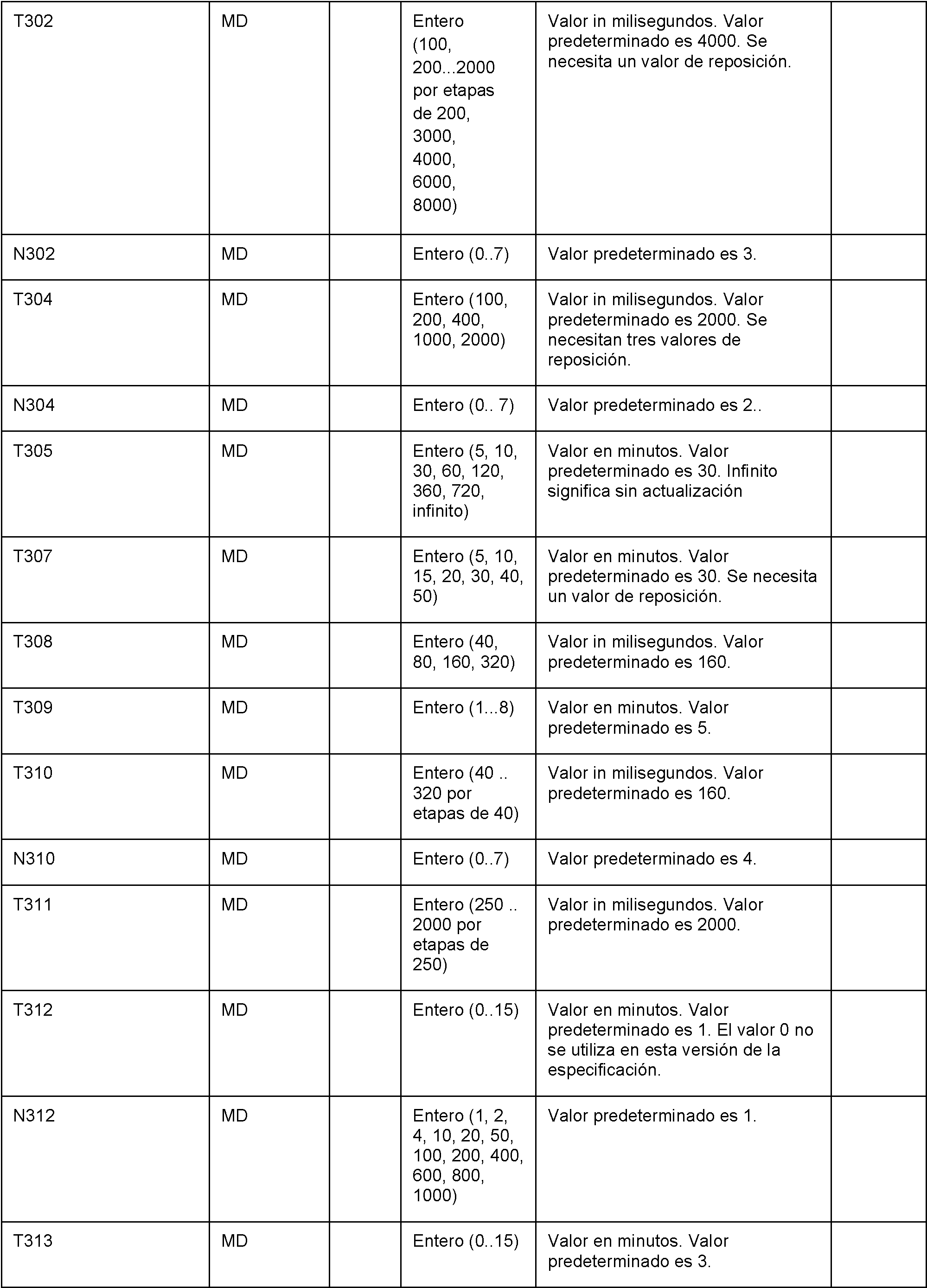

13.4.27x SCRI TRIGGERED SCRI IN PCH STATE13.4.27x SCRI TRIGGERED SCRI IN PCH STATE
Esta variable contiene información sobre si se ha activado un mensaje de SIGNALLING CONNECTION RELEASE INDICATION en los estados CELL PCH o URA PCH. Hay una de esas variables en el UE.This variable contains information on whether a SIGNALING CONNECTION RELEASE INDICATION message has been activated in the CELL PCH or URA PCH states. There is one of those variables in the EU.


13.2 Contadores para UE13.2 Counters for UE
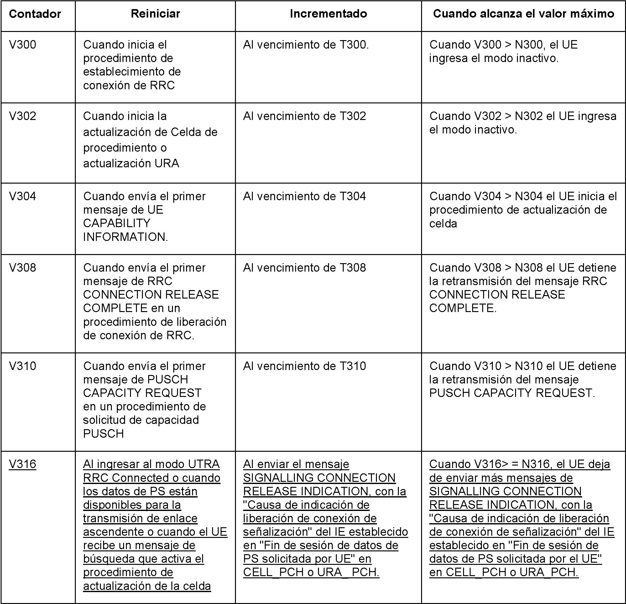
13.3 Constantes y parámetros de UE 13.3 UE parameters and constants


Apéndice DAppendix d
De 25.331 sección 8.2.2, Figura 8.2.2-3: representa una reconfiguración de portador de radio, flujo normal.From 25.331 section 8.2.2, Figure 8.2.2-3: Represents a radio bearer reconfiguration, normal flow.
El mensaje se describe aquí, con la adición propuesta en cursiva y negrita:The message is described here, with the proposed addition in bold italic:
10.2.27 RADIO BEARER RECONFIGURATION10.2.27 RADIO BEARER RECONFIGURATION
Este mensaje se envía desde UTRAN para reconfigurar parámetros relacionados con un cambio de QoS o para liberar y configurar un portador de radio utilizado para la transmisión ptp de servicios MBMS del tipo de difusión. Este procedimiento también puede cambiar la multiplexación de MAC, reconfigurar canales de transporte y canales físicos. Este mensaje también se utiliza para realizar una transferencia del modo GERAN lu a UTRAN.This message is sent from UTRAN to reconfigure parameters related to a QoS change or to release and configure a radio bearer used for ptp transmission of broadcast type MBMS services. This procedure can also change MAC multiplexing, reconfigure transport channels and physical channels. This message is also used to perform a transfer from GERAN lu to UTRAN mode.
RLC-SAP: AM o UM o enviado a través del modo GERAN lu RLC-SAP: AM or UM or sent via GERAN lu mode
Canal lógico: DCCH o enviado a través del modo GERAN lu Logical channel: DCCH or sent via GERAN lu mode
Dirección: UTRAN ^ UEAddress: UTRAN ^ UE

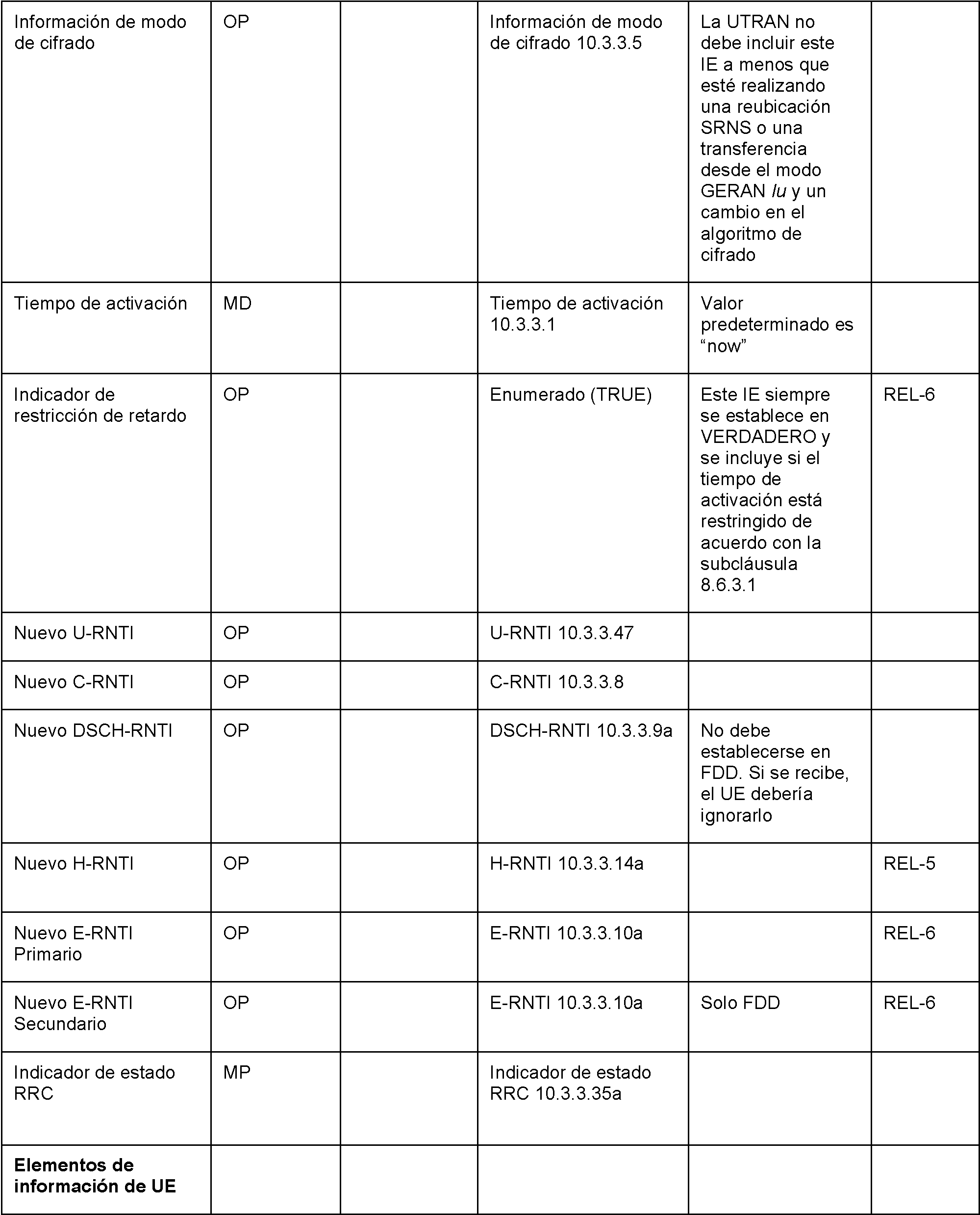


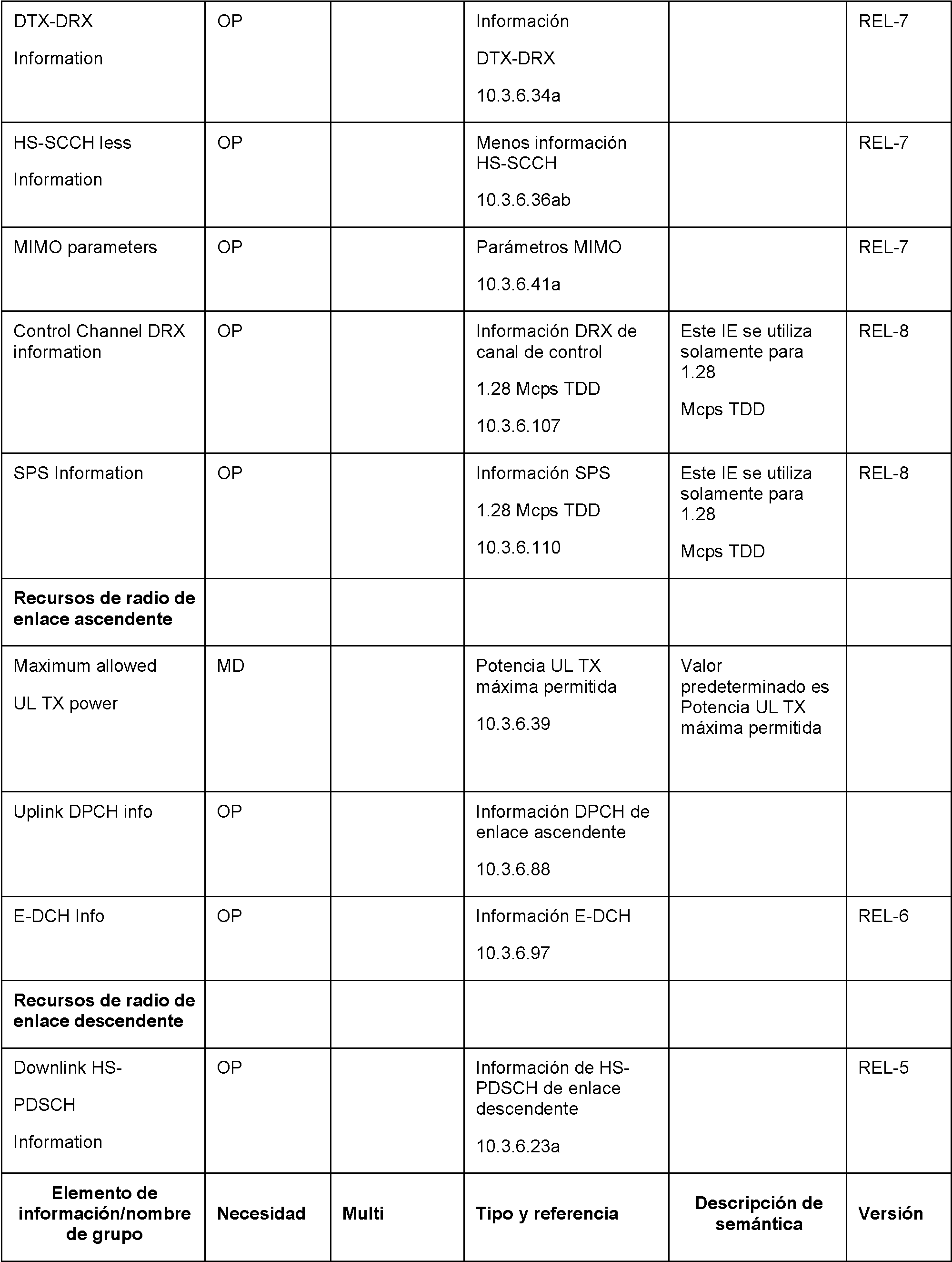


Claims (12)
Applications Claiming Priority (2)
| Application Number | Priority Date | Filing Date | Title |
|---|---|---|---|
| US26381809P | 2009-11-23 | 2009-11-23 | |
| PCT/EP2010/064860 WO2011060998A1 (en) | 2009-11-23 | 2010-10-05 | State or mode transition triggering based on sri message transmission |
Publications (1)
| Publication Number | Publication Date |
|---|---|
| ES2805149T3 true ES2805149T3 (en) | 2021-02-10 |
Family
ID=43432006
Family Applications (1)
| Application Number | Title | Priority Date | Filing Date |
|---|---|---|---|
| ES10768896T Active ES2805149T3 (en) | 2009-11-23 | 2010-10-05 | State or mode transition trigger based on the transmission of a connection release signaling indication message |
Country Status (12)
| Country | Link |
|---|---|
| US (2) | US9144104B2 (en) |
| EP (1) | EP2505034B1 (en) |
| JP (2) | JP5525621B2 (en) |
| KR (1) | KR101417550B1 (en) |
| CN (2) | CN102783242A (en) |
| AU (1) | AU2010321205B2 (en) |
| BR (1) | BR112012012351B1 (en) |
| CA (1) | CA2781497C (en) |
| ES (1) | ES2805149T3 (en) |
| HU (1) | HUE049498T2 (en) |
| MX (1) | MX2012005868A (en) |
| WO (1) | WO2011060998A1 (en) |
Families Citing this family (49)
| Publication number | Priority date | Publication date | Assignee | Title |
|---|---|---|---|---|
| ES2396309T3 (en) | 2005-12-14 | 2013-02-20 | Research In Motion Limited | Method and apparatus for radio resource control aimed at a user equipment |
| ES2353609T3 (en) | 2006-05-17 | 2011-03-03 | Research In Motion Limited | METHOD AND SYSTEM FOR INDICATION OF SIGNALING CONNECTION RELEASE IN A UMTS NETWORK. |
| US20080049662A1 (en) * | 2006-08-25 | 2008-02-28 | Research In Motion Limited | Apparatus, and associated method, for releasing a data-service radio resource allocated to a data-service-capable mobile node |
| ATE553628T1 (en) | 2007-11-13 | 2012-04-15 | Research In Motion Ltd | METHOD AND APPARATUS FOR STATUS/MODE TRANSITIONS |
| ES2896335T3 (en) | 2008-11-10 | 2022-02-24 | Blackberry Ltd | Method and apparatus of transition to an efficient battery state or configuration indicating end of data transmission |
| MX2012005873A (en) | 2009-11-23 | 2012-11-30 | Research In Motion Ltd | Method and apparatus for state/mode transitioning. |
| KR101417550B1 (en) | 2009-11-23 | 2014-07-08 | 블랙베리 리미티드 | State or mode transition triggering based on sri message transmission |
| CA2781558C (en) | 2009-11-23 | 2021-06-29 | Research In Motion Limited | Method and apparatus for state/mode transitioning |
| JP5583225B2 (en) * | 2009-11-24 | 2014-09-03 | ブラックベリー リミテッド | Method and apparatus for state / mode transition |
| US8983532B2 (en) | 2009-12-30 | 2015-03-17 | Blackberry Limited | Method and system for a wireless communication device to adopt varied functionalities based on different communication systems by specific protocol messages |
| KR101674221B1 (en) | 2010-01-28 | 2016-11-09 | 엘지전자 주식회사 | Apparatus and method of reporting logged measurement in wireless communication system |
| BR112012012353A2 (en) * | 2010-02-10 | 2016-03-22 | Research In Motion Ltd | method and apparatus for mode / state transition |
| US8744534B2 (en) | 2010-04-30 | 2014-06-03 | Apple Inc. | Methods and apparatus for preserving battery resources in a mobile communication device |
| US9794980B2 (en) * | 2010-10-01 | 2017-10-17 | Nokia Solutions And Networks Oy | Radio resource control connection release message wait timer |
| US8914034B2 (en) | 2011-05-26 | 2014-12-16 | At&T Mobility Ii Llc | Long-term evolution circuit switched fall back enhancements |
| BR112013032846A2 (en) * | 2011-06-28 | 2017-02-21 | Ericsson Telefon Ab L M | technique for managing broadcast media traffic on a network entity |
| US9007972B2 (en) | 2011-07-01 | 2015-04-14 | Intel Corporation | Communication state transitioning control |
| US20130100820A1 (en) * | 2011-10-19 | 2013-04-25 | Qualcomm Incororated | Maintaining a user equipment in a shared channel state in a wireless communications system |
| EP2777358B1 (en) | 2011-11-11 | 2018-01-10 | BlackBerry Limited | Method and apparatus for user equipment state transition |
| US8909306B2 (en) | 2011-12-05 | 2014-12-09 | Qualcomm Innovation Center, Inc. | Method to conserve power on a wireless mobile device using web browser state knowledge |
| CN103503491A (en) * | 2011-12-19 | 2014-01-08 | 华为技术有限公司 | Method, device and system for service response |
| CN103249100B (en) | 2012-02-03 | 2018-05-01 | 中兴通讯股份有限公司 | A kind of method and terminal for handling data transmission service |
| US9526091B2 (en) | 2012-03-16 | 2016-12-20 | Intel Corporation | Method and apparatus for coordination of self-optimization functions in a wireless network |
| CN102647733B (en) * | 2012-04-05 | 2015-06-24 | 中国联合网络通信集团有限公司 | Dynamic adjusting method of PS (Packet Switch) permanent timer and RNC (Radio Network Controller) |
| DE102012206194A1 (en) * | 2012-04-16 | 2013-10-17 | Robert Bosch Gmbh | Multi-part insulation element, in particular for a fuel injection device |
| US8937880B2 (en) * | 2012-05-09 | 2015-01-20 | Telefonaktiebolaget L M Ericsson (Publ) | System and method for managing state transitions in a wireless communications network |
| JP5668022B2 (en) * | 2012-05-30 | 2015-02-12 | 株式会社Nttドコモ | State transition timer setting system, mobile device, mobile communication system, and state transition timer setting method |
| US9445364B2 (en) * | 2012-08-02 | 2016-09-13 | Telefonaktiebolaget L M Ericsson (Publ) | Systems and methods for blocking excessive transmitter message signaling |
| WO2014022962A1 (en) | 2012-08-06 | 2014-02-13 | 华为技术有限公司 | Signalling sending method and related device |
| US9781767B2 (en) | 2012-08-24 | 2017-10-03 | Samsung Electronics Co., Ltd. | Method for achieving fast dormancy of user equipment (UE) in Cell—PCH or URA—PCH state in UMTS |
| EP2910081B1 (en) * | 2012-10-16 | 2020-12-02 | Telefonaktiebolaget LM Ericsson (publ) | Methods for deciding when to switch between communication channel states, and network nodes therefor |
| US9781676B2 (en) | 2012-10-24 | 2017-10-03 | Blackberry Limited | System and method for reducing power consumption based on data activity sensitive timers |
| US9515793B2 (en) * | 2012-11-29 | 2016-12-06 | Telefonaktiebolaget Lm Ericsson (Publ) | Network resource configuration |
| WO2014085980A1 (en) | 2012-12-04 | 2014-06-12 | Qualcomm Incorporated | Apparatus and method for enhanced mobile power management |
| WO2014158067A1 (en) * | 2013-03-28 | 2014-10-02 | Telefonaktiebolaget L M Ericsson (Publ) | Optimizing channel state switch based on the traffic volume indicator (tvi) values associated with throughputs on the communication links |
| GB2514357A (en) | 2013-05-20 | 2014-11-26 | Nec Corp | Communications system |
| CN105393470B (en) * | 2013-08-08 | 2018-11-02 | 英特尔Ip公司 | The methods, devices and systems adjusted for the electrical tilt angle in multi-input multi-output system |
| US9271326B2 (en) * | 2013-08-22 | 2016-02-23 | Verizon Patent And Licensing Inc. | Radio resource control dormancy timer based on traffic type |
| CN106031277B (en) * | 2015-01-29 | 2018-11-30 | 华为技术有限公司 | Radio bearer method for reconfiguration, method for building up, user equipment and base station |
| WO2017199789A1 (en) * | 2016-05-20 | 2017-11-23 | 株式会社Nttドコモ | User equipment, base station and signal transmission method |
| US11382042B2 (en) | 2017-10-04 | 2022-07-05 | Qualcomm Incorporated | Enhanced power savings through mobile initiated dormancy |
| US11696127B2 (en) * | 2017-11-16 | 2023-07-04 | Telefonaktiebolaget Lm Ericsson (Publ) | Replay protection for resume procedure |
| CN112020881A (en) * | 2018-06-18 | 2020-12-01 | 谷歌有限责任公司 | 5G NR fast low power mode |
| CN110636627B (en) * | 2018-06-21 | 2021-01-08 | 维沃移动通信有限公司 | Resource request method and user equipment |
| US11452169B2 (en) * | 2018-08-15 | 2022-09-20 | Google Llc | Preventing inadvertent idle mode in multi-node connectivity environments |
| ES3058687T3 (en) * | 2019-02-15 | 2026-03-12 | Nokia Technologies Oy | Optimized multi connectivity and data duplication |
| US11785664B2 (en) * | 2019-03-29 | 2023-10-10 | Samsung Electronics Co., Ltd. | Method and apparatus for performing RRC state transition in wireless communication network |
| US20210337481A1 (en) * | 2020-04-23 | 2021-10-28 | Qualcomm Incorporated | Application information aided fast dormancy |
| CN112073270B (en) * | 2020-09-15 | 2022-03-25 | 新华三信息安全技术有限公司 | Link fault detection method and device |
Family Cites Families (167)
| Publication number | Priority date | Publication date | Assignee | Title |
|---|---|---|---|---|
| JP3161910B2 (en) | 1994-07-26 | 2001-04-25 | シャープ株式会社 | Communication device |
| JPH0955764A (en) | 1995-08-14 | 1997-02-25 | Nippon Telegr & Teleph Corp <Ntt> | Wireless packet communication method |
| FI103454B (en) | 1996-04-01 | 1999-06-30 | Nokia Telecommunications Oy | Control of the operation of a mobile station in a packet radio system |
| US5812636A (en) | 1996-09-06 | 1998-09-22 | Northern Telecom Limited | System and method for faulty mobile unit isolation |
| KR100232881B1 (en) | 1997-10-08 | 1999-12-01 | 윤종용 | Receiver power control method and radio call receiver accordingly |
| JPH11313370A (en) | 1998-04-28 | 1999-11-09 | Toshiba Corp | Mobile packet communication system and its data communication device, base station device and mobile terminal device |
| JPH11331947A (en) | 1998-05-18 | 1999-11-30 | Nippon Telegr & Teleph Corp <Ntt> | Wireless station, wireless data communication method, and storage medium for program |
| US6064340A (en) | 1998-07-02 | 2000-05-16 | Intersil Corporation | Electrostatic discharge locating apparatus and method |
| KR20000014143A (en) | 1998-08-14 | 2000-03-06 | 서평원 | Improved method of transmitting pilot strength measurement message in communication system |
| FI108203B (en) | 1998-11-27 | 2001-11-30 | Nokia Mobile Phones Ltd | Method and apparatus for transmitting information in a packet radio service |
| US6223044B1 (en) | 1998-12-18 | 2001-04-24 | Telefonaktiebolaget Lm Ericsson | Adaptive location level |
| CN1169400C (en) | 1999-01-04 | 2004-09-29 | 艾利森电话股份有限公司 | bearer service negotiation |
| US6275712B1 (en) | 1999-02-26 | 2001-08-14 | Nokia Mobile Phones Ltd | Mobile station control states based on available power |
| EP1033846A1 (en) | 1999-03-01 | 2000-09-06 | Alcatel | Process for controlling uplink packet transmission in a wireless communication network |
| US6377790B1 (en) | 1999-03-08 | 2002-04-23 | Sharp Laboratories Of America, Inc. | Mobile-initiated, packet switched communications method |
| US6965778B1 (en) | 1999-04-08 | 2005-11-15 | Ipr Licensing, Inc. | Maintenance of channel usage in a wireless communication system |
| CA2333135C (en) | 1999-04-12 | 2004-05-25 | Hyun-Jung Mun | Method for controlling gated transmission of dedicated channel in w-cdma communication system |
| SE522068C2 (en) | 1999-07-15 | 2004-01-13 | Ericsson Telefon Ab L M | Method and apparatus for providing radio access carrier services |
| FI107674B (en) | 1999-08-30 | 2001-09-14 | Nokia Mobile Phones Ltd | Procedure for optimizing data transmission in a packet switched wireless communication system |
| US6657984B1 (en) | 1999-10-29 | 2003-12-02 | Samsung Electronics, Co., Ltd. | System and method providing backward compatibility of radio link protocols in a wireless network |
| US6654360B1 (en) | 2000-01-10 | 2003-11-25 | Qualcomm Incorporated | Method and system for providing dormant mode wireless packet data services |
| US6593850B1 (en) * | 2000-01-27 | 2003-07-15 | Pittway Corp. | Wireless intrusion detector with test mode |
| FI110651B (en) | 2000-02-22 | 2003-02-28 | Nokia Corp | Method for checking the amount of transmitted data |
| FI110352B (en) | 2000-02-24 | 2002-12-31 | Nokia Corp | Method and arrangement to optimize the re-establishment of connections in a cellular radio system that supports real-time and non-real-time communications |
| KR100396509B1 (en) | 2000-06-22 | 2003-09-02 | 삼성전자주식회사 | Apparatus for gated transmission of dedicated physical control channel and method thereof in mobile communication system |
| US6748246B1 (en) | 2000-07-05 | 2004-06-08 | Telefonaktiebolaget Lm Ericsson (Publ) | Method and apparatus for selecting an access technology in a multi-mode terminal |
| FI109628B (en) | 2000-08-21 | 2002-09-13 | Nokia Corp | Method for Reducing the Power Consumption of a Wireless Terminal, a Communication System, and a Wireless Terminal |
| US6690655B1 (en) | 2000-10-19 | 2004-02-10 | Motorola, Inc. | Low-powered communication system and method of operation |
| US6845236B2 (en) | 2000-11-01 | 2005-01-18 | Lg Electronics Inc. | Method for concurrent multiple services in a mobile communication system |
| US6970438B2 (en) | 2001-02-16 | 2005-11-29 | Nokia Mobile Phones Ltd. | Method and device for downlink packet switching |
| US7046992B2 (en) | 2001-05-11 | 2006-05-16 | Telefonaktiebolaget Lm Ericsson (Publ) | Authentication of termination messages in telecommunications system |
| JP4015428B2 (en) | 2001-05-16 | 2007-11-28 | 株式会社日立コミュニケーションテクノロジー | RADIO BASE STATION / WIRELESS BASE STATION CONTROL DEVICE, RADIO TERMINAL, AND STATE CONTROL METHOD HAVING IN-ACTIVITY TIMER |
| US7337019B2 (en) | 2001-07-16 | 2008-02-26 | Applied Materials, Inc. | Integration of fault detection with run-to-run control |
| US7221670B2 (en) | 2001-08-13 | 2007-05-22 | Motorola, Inc. | Apparatus and method for supplying information concerning packet data to a base station |
| JP4039851B2 (en) | 2001-12-07 | 2008-01-30 | 株式会社エヌ・ティ・ティ・ドコモ | Mobile communication terminal, application program execution state control method, application program, and record recording application program |
| US7609673B2 (en) | 2002-02-08 | 2009-10-27 | Telefonaktiebolaget Lm Ericsson (Publ) | Packet-based conversational service for a multimedia session in a mobile communications system |
| KR100765123B1 (en) | 2002-02-16 | 2007-10-11 | 엘지전자 주식회사 | How to reassign the SRS |
| DE60314331T2 (en) | 2002-05-03 | 2008-02-14 | Innovative Sonic Ltd., Road Town | Method of cell updating via idle for the purpose of saving power in a UMTS mobile after a failed radio connection. |
| US7054630B2 (en) | 2002-05-13 | 2006-05-30 | Qualcomm Incorporated | Selective processing of the common control channel |
| JPWO2003105519A1 (en) | 2002-06-05 | 2005-10-13 | 株式会社エヌ・ティ・ティ・ドコモ | Server, mobile communication system, location information management method, radio base station, mobile station, calling method and mobile communication method in mobile communication system |
| US7068636B2 (en) | 2002-06-21 | 2006-06-27 | Asustek Computer Inc. | Method for determining RLC entity re-establishment during SRNS relocation |
| JP4197408B2 (en) | 2002-06-26 | 2008-12-17 | パナソニック株式会社 | COMMUNICATION SYSTEM, TERMINAL DEVICE, AND RELAY STATION SELECTION METHOD FOR COMMUNICATION SYSTEM |
| US20040192312A1 (en) | 2002-07-16 | 2004-09-30 | Jia-Ru Li | Communication system for voice and data with wireless TCP server |
| US6961570B2 (en) | 2002-07-17 | 2005-11-01 | Asustek Computer Inc. | Handling of a wireless device re-entering a service area |
| US7152111B2 (en) | 2002-08-15 | 2006-12-19 | Digi International Inc. | Method and apparatus for a client connection manager |
| KR100510651B1 (en) | 2002-09-12 | 2005-08-31 | 엘지전자 주식회사 | Method for Managing Resource of Mobile Communication System |
| US7277392B2 (en) | 2002-10-01 | 2007-10-02 | Motorola, Inc. | Method and apparatus for managing the usage of data link resources |
| CN100421499C (en) * | 2002-10-23 | 2008-09-24 | 诺基亚公司 | Radio resource control method in mobile communication system, radio communication system, and network element |
| US7437172B2 (en) | 2002-12-10 | 2008-10-14 | Qualcomm Incorporated | Discontinuous transmission (DTX) detection in wireless communication systems |
| KR100658650B1 (en) | 2002-12-12 | 2006-12-15 | 후아웨이 테크놀러지 컴퍼니 리미티드 | A process method about the service connection between the wireless local area network and user terminal |
| ATE517538T1 (en) | 2002-12-16 | 2011-08-15 | Research In Motion Ltd | METHOD AND DEVICE FOR REDUCING ENERGY CONSUMPTION IN A CDMA COMMUNICATIONS DEVICE |
| SE0300047D0 (en) | 2003-01-08 | 2003-01-08 | Ericsson Telefon Ab L M | MBMS in UTRAN |
| US6822973B2 (en) | 2003-02-18 | 2004-11-23 | Motorola, Inc. | Apparatus and method for implementing a reduced slotted mode in a communication system |
| US7720960B2 (en) | 2003-03-04 | 2010-05-18 | Cisco Technology, Inc. | Method and apparatus providing prepaid billing for network services using explicit service authorization in an access server |
| US7787413B2 (en) | 2003-03-14 | 2010-08-31 | Nortel Networks Limited | Method for mobile station request release of multiple packet data service sessions simultaneously using resource release request messages |
| JP4350565B2 (en) | 2003-03-27 | 2009-10-21 | キヤノン株式会社 | Information processing apparatus and method |
| FR2854756B1 (en) | 2003-05-07 | 2005-08-12 | Evolium Sas | METHOD FOR ESTABLISHING CONNECTION IN A MOBILE RADIOCOMMUNICATION SYSTEM |
| US7406314B2 (en) | 2003-07-11 | 2008-07-29 | Interdigital Technology Corporation | Wireless transmit receive unit having a transition state for transitioning from monitoring to duplex connected states and method |
| KR20050014984A (en) | 2003-08-01 | 2005-02-21 | 삼성전자주식회사 | Methoed for retransmitting rrc connection request in a mobile communication system which support mbms |
| US20050032555A1 (en) | 2003-08-07 | 2005-02-10 | Iqbal Jami | Method of intermittent activation of receiving circuitry of a mobile user terminal |
| KR100548393B1 (en) | 2003-08-20 | 2006-02-02 | 엘지전자 주식회사 | Packet service performance improvement method of mobile communication terminal |
| TWI245513B (en) * | 2003-08-26 | 2005-12-11 | Ind Tech Res Inst | Method and apparatus for controlling multi-radio access |
| US7130668B2 (en) | 2003-09-01 | 2006-10-31 | Samsung Electronics Co., Ltd. | Method and system for controlling sleep mode in broadband wireless access communication system |
| US7634554B2 (en) | 2003-09-18 | 2009-12-15 | Cisco Technology, Inc. | TTL exploration technique for determining capabilities and configuration of a peer router |
| GB0323246D0 (en) | 2003-10-03 | 2003-11-05 | Fujitsu Ltd | Virtually centralized uplink scheduling |
| AU2003272166A1 (en) | 2003-10-16 | 2005-05-05 | Telefonaktiebolaget Lm Ericsson (Publ) | Access to cdma/umts services over a wlan access point, using a gateway node between the wlan access point and the service providing network |
| US7623530B2 (en) | 2003-11-20 | 2009-11-24 | Nokia Corporation | Indication of service flow termination by network control to policy decision function |
| JP2005175831A (en) | 2003-12-10 | 2005-06-30 | Ntt Docomo Inc | Communication terminal and program |
| FI20031912A0 (en) | 2003-12-29 | 2003-12-29 | Nokia Corp | Procedure and system for controlling a real-time communication service |
| FI20031911A0 (en) | 2003-12-29 | 2003-12-29 | Nokia Corp | Procedure and system for controlling an access network service at a real-time data service |
| US20050143056A1 (en) | 2003-12-31 | 2005-06-30 | Iyer Prakash R. | Method and apparatus for providing push-to-talk services in a cellular communication system |
| US20050149940A1 (en) | 2003-12-31 | 2005-07-07 | Sychron Inc. | System Providing Methodology for Policy-Based Resource Allocation |
| US7346353B2 (en) | 2004-01-09 | 2008-03-18 | M-Stack Limited | Apparatus and method for implementing detection of system information changes in universal mobile telecommunications systems |
| KR100664278B1 (en) | 2004-01-09 | 2007-01-04 | 엘지전자 주식회사 | MBMS wireless communication system |
| US7440459B2 (en) | 2004-02-02 | 2008-10-21 | Lucent Technologies Inc. | Methods of detecting protocol support in wireless communication systems |
| US7480267B2 (en) | 2004-02-06 | 2009-01-20 | M-Stack Limited | Apparatus and method for operating a communications device in a mobile communications network |
| US7519035B2 (en) | 2004-02-23 | 2009-04-14 | Sharp Laboratories Of America, Inc. | Method to negotiate consumed power versus medium occupancy time in MIMO based WLAN systems using admission control |
| GB0406664D0 (en) | 2004-03-24 | 2004-04-28 | Samsung Electronics Co Ltd | Mobile communications |
| US7636331B2 (en) * | 2004-04-19 | 2009-12-22 | Lg Electronic Inc. | Transmission of control information in wireless communication system |
| KR100703487B1 (en) | 2004-04-21 | 2007-04-03 | 삼성전자주식회사 | Efficient Packet Data Service Operation in the MMTS System |
| US20050245267A1 (en) | 2004-04-30 | 2005-11-03 | Guethaus Roland J | Methods of allocating a channel to baseband processing units in a communication system |
| EP1596616A1 (en) | 2004-05-14 | 2005-11-16 | Research In Motion Limited | Method and apparatus for expeditiously releasing network resources for a mobile station based on low battery and lost signal conditions |
| US20050265350A1 (en) | 2004-05-28 | 2005-12-01 | Murali Narasimha | Concurrent packet data session set-up for push-to-talk over cellular |
| US7580388B2 (en) | 2004-06-01 | 2009-08-25 | Lg Electronics Inc. | Method and apparatus for providing enhanced messages on common control channel in wireless communication system |
| US7181215B2 (en) | 2004-06-02 | 2007-02-20 | Sony Ericsson Mobile Communications Ab | Automatic GPRS/EDGE re-attach |
| US8855572B2 (en) | 2004-06-16 | 2014-10-07 | Qualcomm Incorporated | Method and apparatus for link control in wireless communications |
| KR100605625B1 (en) | 2004-06-17 | 2006-07-31 | 엘지전자 주식회사 | How to release session of UTM system |
| US7089012B2 (en) | 2004-07-29 | 2006-08-08 | Motorola, Inc. | Method and system for use in reducing cost associated with lost connections in wireless communication |
| CN1998258A (en) | 2004-08-05 | 2007-07-11 | 三菱电机株式会社 | Base station, mobile communication terminal device, and primary cell selection method |
| US7529354B2 (en) | 2004-08-10 | 2009-05-05 | Nokia Corporation | Method of managing a connection release, corresponding system and device |
| US8254921B2 (en) | 2004-08-12 | 2012-08-28 | Qualcomm Incorporated | Default configurations with differential encoding in a wireless communication system |
| BRPI0511645A (en) | 2004-08-13 | 2008-01-02 | Lg Electronics Inc | radio resource control connection establishment in wireless communication system |
| CN101036099A (en) | 2004-09-03 | 2007-09-12 | 田纳西太平洋集团有限公司 | Centralized management of digital rights licensing |
| US7904094B2 (en) | 2004-10-27 | 2011-03-08 | Motorola Mobility, Inc. | Method for reducing wireless communication procedure failure |
| US20060094478A1 (en) | 2004-11-04 | 2006-05-04 | Lg Electronics Inc. | Mobile power handling method and apparatus |
| US8379553B2 (en) | 2004-11-22 | 2013-02-19 | Qualcomm Incorporated | Method and apparatus for mitigating the impact of receiving unsolicited IP packets at a wireless device |
| US20060176167A1 (en) | 2005-01-25 | 2006-08-10 | Laser Shield Systems, Inc. | Apparatus, system, and method for alarm systems |
| US7925290B2 (en) | 2005-03-31 | 2011-04-12 | Qualcomm Incorporated | System and method for efficiently providing high-performance dispatch services in a wireless system |
| JP4577505B2 (en) | 2005-03-31 | 2010-11-10 | 日本電気株式会社 | Method for contention relief between downlink RRC message and inter-cell movement of mobile station in mobile communication system |
| US7283819B2 (en) | 2005-04-25 | 2007-10-16 | Research In Motion Limited | Method and apparatus for CDMA timer-based registration on a mobile device |
| EP2566239B1 (en) | 2005-06-15 | 2015-12-30 | Intellectual Ventures I LLC | RRC Signalling for Fast HS-DSCH Serving Cell Change |
| US20060293067A1 (en) | 2005-06-27 | 2006-12-28 | Leung Kin K | Method and apparatus for controlling sleep intervals of a mobile unit |
| DE202005021930U1 (en) | 2005-08-01 | 2011-08-08 | Corning Cable Systems Llc | Fiber optic decoupling cables and pre-connected assemblies with toning parts |
| JP4767626B2 (en) | 2005-08-24 | 2011-09-07 | ドコモ・テクノロジ株式会社 | Mobile station, radio access network apparatus, mobile switching center, and communication service access method |
| JP2009506609A (en) | 2005-08-24 | 2009-02-12 | ノキア コーポレイション | Apparatus, method, and computer program for constructing radio link protocol of internet protocol flow |
| US8094595B2 (en) | 2005-08-26 | 2012-01-10 | Qualcomm Incorporated | Method and apparatus for packet communications in wireless systems |
| US7643838B2 (en) | 2005-09-29 | 2010-01-05 | Motorola, Inc. | Integrity protection count synchronization method |
| US7894375B2 (en) | 2005-10-31 | 2011-02-22 | Research In Motion Limited | Method, and associated apparatus, for transitioning communications of hybrid access terminal between communication systems |
| US7720482B2 (en) | 2005-10-31 | 2010-05-18 | Research In Motion Limited | Method and apparatus for transitioning between EVDO and CDMA 1X systems using redundant data call blockings |
| US7761097B2 (en) | 2005-10-31 | 2010-07-20 | Research In Motion Limited | Apparatus, and associated method, for permitting communication system transition based upon signal threshold determination |
| US7768962B2 (en) | 2005-11-01 | 2010-08-03 | Nokia Corporation | HSUPA HARQ process flushing |
| GB2469229B (en) | 2005-11-04 | 2011-02-02 | Nec Corp | Wireless communication system and method of controlling a transmission power |
| ES2396309T3 (en) | 2005-12-14 | 2013-02-20 | Research In Motion Limited | Method and apparatus for radio resource control aimed at a user equipment |
| CN101341673A (en) | 2005-12-19 | 2009-01-07 | Lg电子株式会社 | Method to read dynamic system information block |
| EP2384066B1 (en) | 2005-12-22 | 2013-04-24 | Electronics and Telecommunications Research Institute | Method for discontinuous transmission/reception operation for reducing power consumption in cellular system |
| US7353120B2 (en) | 2006-01-24 | 2008-04-01 | Research In Motion Limited | Electrostatic discharge monitoring and manufacturing process control system |
| WO2007097670A1 (en) | 2006-02-27 | 2007-08-30 | Telefonaktiebolaget L M Ericsson (Publ) | Method and apparatus for communication |
| WO2007137519A1 (en) | 2006-05-18 | 2007-12-06 | Huawei Technologies Co., Ltd. | A method and system for a ue in spare mode logging out a network |
| CN101411095B (en) | 2006-03-28 | 2013-06-19 | 三星电子株式会社 | Method and device for discontinuous reception of a connected terminal in a mobile communication system |
| JP5019400B2 (en) | 2006-04-25 | 2012-09-05 | サムスン エレクトロニクス カンパニー リミテッド | Wireless connection setting method and apparatus in mobile communication system |
| US9614648B2 (en) | 2006-04-29 | 2017-04-04 | Philips Lighting Holding B.V. | Method and apparatus for controlling energy expanding of sensor network nodes |
| ES2353609T3 (en) * | 2006-05-17 | 2011-03-03 | Research In Motion Limited | METHOD AND SYSTEM FOR INDICATION OF SIGNALING CONNECTION RELEASE IN A UMTS NETWORK. |
| BRPI0705715B1 (en) | 2006-05-17 | 2019-12-24 | Blackberry Ltd | method and system for signaling indication of cause of release in an umts network |
| US8265034B2 (en) | 2006-05-17 | 2012-09-11 | Research In Motion Limited | Method and system for a signaling connection release indication |
| CN100499869C (en) | 2006-05-24 | 2009-06-10 | 华为技术有限公司 | Terminal equipment accessing method and system |
| US7852817B2 (en) | 2006-07-14 | 2010-12-14 | Kineto Wireless, Inc. | Generic access to the Iu interface |
| EP1892895A1 (en) | 2006-08-25 | 2008-02-27 | Research In Motion Limited | Apparatus, and associated method, for releasing a data service radio resource allocated to a data service capable mobile node |
| US20080049662A1 (en) | 2006-08-25 | 2008-02-28 | Research In Motion Limited | Apparatus, and associated method, for releasing a data-service radio resource allocated to a data-service-capable mobile node |
| US8630604B2 (en) | 2006-11-17 | 2014-01-14 | Industrial Technology Research Institute | Communication methods and devices for dual-mode communication systems |
| US8311046B2 (en) | 2006-11-28 | 2012-11-13 | Core Wireless Licensing S.A.R.L. | Method for the delivery of messages in a communication system |
| JP2008141252A (en) | 2006-11-29 | 2008-06-19 | Sharp Corp | COMMUNICATION DEVICE, COMMUNICATION METHOD, COMMUNICATION CIRCUIT, COMMUNICATION SYSTEM, PROGRAM, AND COMPUTER-READABLE RECORDING MEDIUM CONTAINING THE PROGRAM |
| US8515478B2 (en) | 2006-12-18 | 2013-08-20 | Qualcomm Incorporated | Fast state transition for a UE with reconfiguration over paging |
| EP2120480A4 (en) | 2007-03-06 | 2013-12-11 | Ntt Docomo Inc | MOBILE STATION, BASE STATION DEVICE, WIRELESS COMMUNICATION SYSTEM, AND COMMUNICATION CONTROL METHOD |
| KR101381475B1 (en) | 2007-04-13 | 2014-04-04 | 삼성전자주식회사 | A method for transitioning a radio resource control state of a user terminal to an idle state, a system for the same, and a terminal thereof |
| US20080304510A1 (en) | 2007-06-08 | 2008-12-11 | Hai Qu | Method and apparatus for controlling radio connection based on inputs from applications |
| US9887813B2 (en) | 2007-06-13 | 2018-02-06 | Qualcomm Incorporated | Protocol data unit recovery |
| US20090028084A1 (en) | 2007-07-25 | 2009-01-29 | High Tech Computer, Corp. | Method for reducing user equipment power consumption under a communication network |
| KR101422032B1 (en) | 2007-08-10 | 2014-07-23 | 엘지전자 주식회사 | Method of setting a channel in a wireless communication system |
| EP2271168A1 (en) | 2007-08-20 | 2011-01-05 | Research In Motion Limited | Method and system for a signaling connection release indication |
| KR100937432B1 (en) | 2007-09-13 | 2010-01-18 | 엘지전자 주식회사 | Radio Resource Allocation Method in Wireless Communication System |
| KR101370909B1 (en) | 2007-10-01 | 2014-03-19 | 엘지전자 주식회사 | Method of Fast Uplink Data Transmission for handover |
| KR101487557B1 (en) | 2007-10-23 | 2015-01-29 | 엘지전자 주식회사 | Method of transmitting data of common control channel |
| ATE553628T1 (en) | 2007-11-13 | 2012-04-15 | Research In Motion Ltd | METHOD AND APPARATUS FOR STATUS/MODE TRANSITIONS |
| CN101453742B (en) * | 2007-12-04 | 2010-09-08 | 大唐移动通信设备有限公司 | Cell updating method, equipment and system |
| TW200931918A (en) | 2007-12-07 | 2009-07-16 | Interdigital Patent Holdings | Method and apparatus for supporting configuration and control of the RLC and PDCP sub-layers |
| EP2238802B1 (en) | 2007-12-10 | 2018-06-27 | InterDigital Patent Holdings, Inc. | Method and apparatus for triggering radio link control packet discard and radio link control re-establishment |
| EP2238801B1 (en) | 2007-12-20 | 2013-04-17 | Telefonaktiebolaget LM Ericsson (publ) | Releasing common enhanced dedicated channel, e-dch, radio resources |
| WO2009104086A1 (en) | 2008-02-22 | 2009-08-27 | Nokia Corporation | Mobile equipment autonomous quick release detection |
| US20090221277A1 (en) | 2008-02-29 | 2009-09-03 | Palm, Inc. | Disconnection techniques in wireless communications networks |
| GB2461159B (en) | 2008-06-18 | 2012-01-04 | Lg Electronics Inc | Method for transmitting Mac PDUs |
| US8824305B2 (en) | 2008-07-09 | 2014-09-02 | Qualcomm Incorporated | Paging schemes for local network access |
| US8737294B2 (en) | 2008-08-11 | 2014-05-27 | Via Telecom Co., Ltd. | Apparatus and method for handling RLC retransmission failure according to activation status of security mode |
| JP5233504B2 (en) | 2008-08-25 | 2013-07-10 | 富士通株式会社 | Route control apparatus and packet discarding method |
| US9094910B2 (en) | 2008-09-09 | 2015-07-28 | Htc Corporation | Methods utilized in mobile device for handling situations when time alignment timer expires, and mobile device thereof |
| US8391239B2 (en) | 2008-09-22 | 2013-03-05 | Qualcomm Incorporated | Bearer count alignment during inter-rat handover |
| ES2896335T3 (en) | 2008-11-10 | 2022-02-24 | Blackberry Ltd | Method and apparatus of transition to an efficient battery state or configuration indicating end of data transmission |
| CN102365837B (en) | 2009-03-29 | 2014-05-14 | Lg电子株式会社 | Method for transmitting control information in wireless communication system and apparatus therefor |
| US8902827B2 (en) | 2009-04-21 | 2014-12-02 | Htc Corporation | Relay for handling data forwarding in a wireless communication system and related method for controlling the same |
| US8638711B2 (en) | 2009-08-11 | 2014-01-28 | Qualcomm Incorporated | Systems and methods of maintaining core network status during serving radio network subsystem relocation |
| KR101417550B1 (en) | 2009-11-23 | 2014-07-08 | 블랙베리 리미티드 | State or mode transition triggering based on sri message transmission |
| CA2781558C (en) * | 2009-11-23 | 2021-06-29 | Research In Motion Limited | Method and apparatus for state/mode transitioning |
| MX2012005873A (en) | 2009-11-23 | 2012-11-30 | Research In Motion Ltd | Method and apparatus for state/mode transitioning. |
| JP5583225B2 (en) | 2009-11-24 | 2014-09-03 | ブラックベリー リミテッド | Method and apparatus for state / mode transition |
| US8983532B2 (en) | 2009-12-30 | 2015-03-17 | Blackberry Limited | Method and system for a wireless communication device to adopt varied functionalities based on different communication systems by specific protocol messages |
| BR112012012353A2 (en) | 2010-02-10 | 2016-03-22 | Research In Motion Ltd | method and apparatus for mode / state transition |
| US8594747B2 (en) | 2011-05-06 | 2013-11-26 | Apple Inc. | Adaptive fast dormancy in a mobile device |
| EP2777358B1 (en) | 2011-11-11 | 2018-01-10 | BlackBerry Limited | Method and apparatus for user equipment state transition |
-
2010
- 2010-10-05 KR KR1020127016426A patent/KR101417550B1/en active Active
- 2010-10-05 ES ES10768896T patent/ES2805149T3/en active Active
- 2010-10-05 EP EP10768896.2A patent/EP2505034B1/en active Active
- 2010-10-05 BR BR112012012351-3A patent/BR112012012351B1/en active IP Right Grant
- 2010-10-05 AU AU2010321205A patent/AU2010321205B2/en active Active
- 2010-10-05 WO PCT/EP2010/064860 patent/WO2011060998A1/en not_active Ceased
- 2010-10-05 CN CN201080062345XA patent/CN102783242A/en active Pending
- 2010-10-05 JP JP2012539245A patent/JP5525621B2/en active Active
- 2010-10-05 US US12/897,959 patent/US9144104B2/en active Active
- 2010-10-05 MX MX2012005868A patent/MX2012005868A/en active IP Right Grant
- 2010-10-05 CN CN201610815582.8A patent/CN107018579B/en active Active
- 2010-10-05 HU HUE10768896A patent/HUE049498T2/en unknown
- 2010-10-05 CA CA2781497A patent/CA2781497C/en active Active
-
2011
- 2011-09-26 US US13/244,849 patent/US9119208B2/en active Active
-
2014
- 2014-04-11 JP JP2014082147A patent/JP2014143752A/en not_active Withdrawn
Also Published As
| Publication number | Publication date |
|---|---|
| CA2781497A1 (en) | 2011-05-26 |
| US20120014326A1 (en) | 2012-01-19 |
| JP2014143752A (en) | 2014-08-07 |
| CN107018579B (en) | 2021-02-19 |
| AU2010321205B2 (en) | 2014-09-04 |
| MX2012005868A (en) | 2012-11-30 |
| WO2011060998A1 (en) | 2011-05-26 |
| CA2781497C (en) | 2017-06-27 |
| EP2505034B1 (en) | 2020-05-06 |
| KR101417550B1 (en) | 2014-07-08 |
| US9144104B2 (en) | 2015-09-22 |
| CN107018579A (en) | 2017-08-04 |
| BR112012012351A2 (en) | 2018-01-30 |
| EP2505034A1 (en) | 2012-10-03 |
| AU2010321205A1 (en) | 2012-06-28 |
| US20110249575A1 (en) | 2011-10-13 |
| HUE049498T2 (en) | 2020-09-28 |
| JP5525621B2 (en) | 2014-06-18 |
| JP2013511873A (en) | 2013-04-04 |
| US9119208B2 (en) | 2015-08-25 |
| KR20120096548A (en) | 2012-08-30 |
| CN102783242A (en) | 2012-11-14 |
| BR112012012351B1 (en) | 2021-05-04 |
Similar Documents
| Publication | Publication Date | Title |
|---|---|---|
| ES2805149T3 (en) | State or mode transition trigger based on the transmission of a connection release signaling indication message | |
| ES2385415T3 (en) | Method and apparatus for state / mode transition | |
| AU2010321204B2 (en) | Method and apparatus for state/mode transitioning | |
| AU2010320843B2 (en) | Method and apparatus for state/mode transitioning | |
| JP5551275B2 (en) | Method and apparatus for status / mode transmission | |
| KR20120096546A (en) | Method and apparatus for state/mode transitioning | |
| AU2013248261B2 (en) | Method and apparatus for state/mode transitioning | |
| AU2014203095A1 (en) | State or mode transition triggering based on SRI message transmission |