ES2807750T3 - Autogyro rotor blade - Google Patents
Autogyro rotor blade Download PDFInfo
- Publication number
- ES2807750T3 ES2807750T3 ES16809685T ES16809685T ES2807750T3 ES 2807750 T3 ES2807750 T3 ES 2807750T3 ES 16809685 T ES16809685 T ES 16809685T ES 16809685 T ES16809685 T ES 16809685T ES 2807750 T3 ES2807750 T3 ES 2807750T3
- Authority
- ES
- Spain
- Prior art keywords
- profile
- region
- rotor blade
- autogyro
- autogyro rotor
- Prior art date
- Legal status (The legal status is an assumption and is not a legal conclusion. Google has not performed a legal analysis and makes no representation as to the accuracy of the status listed.)
- Active
Links
- 230000007704 transition Effects 0.000 claims abstract description 54
- 230000007423 decrease Effects 0.000 claims abstract description 27
- 230000000694 effects Effects 0.000 description 7
- 238000010586 diagram Methods 0.000 description 4
- 230000002349 favourable effect Effects 0.000 description 4
- 230000008859 change Effects 0.000 description 3
- 230000009467 reduction Effects 0.000 description 3
- 238000013459 approach Methods 0.000 description 2
- 238000007664 blowing Methods 0.000 description 2
- 230000003247 decreasing effect Effects 0.000 description 2
- 238000006073 displacement reaction Methods 0.000 description 2
- 230000004907 flux Effects 0.000 description 2
- 230000002093 peripheral effect Effects 0.000 description 2
- 230000001133 acceleration Effects 0.000 description 1
- 230000009471 action Effects 0.000 description 1
- 230000006978 adaptation Effects 0.000 description 1
- 230000006399 behavior Effects 0.000 description 1
- 238000010276 construction Methods 0.000 description 1
- 230000024703 flight behavior Effects 0.000 description 1
- 230000006872 improvement Effects 0.000 description 1
- 238000004519 manufacturing process Methods 0.000 description 1
- 230000001105 regulatory effect Effects 0.000 description 1
Classifications
-
- B—PERFORMING OPERATIONS; TRANSPORTING
- B64—AIRCRAFT; AVIATION; COSMONAUTICS
- B64C—AEROPLANES; HELICOPTERS
- B64C27/00—Rotorcraft; Rotors peculiar thereto
- B64C27/02—Gyroplanes
-
- B—PERFORMING OPERATIONS; TRANSPORTING
- B64—AIRCRAFT; AVIATION; COSMONAUTICS
- B64C—AEROPLANES; HELICOPTERS
- B64C27/00—Rotorcraft; Rotors peculiar thereto
- B64C27/32—Rotors
- B64C27/46—Blades
- B64C27/467—Aerodynamic features
-
- B—PERFORMING OPERATIONS; TRANSPORTING
- B64—AIRCRAFT; AVIATION; COSMONAUTICS
- B64C—AEROPLANES; HELICOPTERS
- B64C27/00—Rotorcraft; Rotors peculiar thereto
- B64C27/32—Rotors
- B64C27/46—Blades
- B64C27/473—Constructional features
Landscapes
- Engineering & Computer Science (AREA)
- Mechanical Engineering (AREA)
- Aviation & Aerospace Engineering (AREA)
- Physics & Mathematics (AREA)
- Fluid Mechanics (AREA)
- Structures Of Non-Positive Displacement Pumps (AREA)
- Turbine Rotor Nozzle Sealing (AREA)
- Wind Motors (AREA)
- Handcart (AREA)
- Laminated Bodies (AREA)
Abstract
Pala de rotor de autogiro para la generación de elevación autorrotatoria con una región de perfil interior (9) en el lado de la raíz que tiene un primer perfil (21c), con una región de perfil principal (10) en el lado de la punta que tiene un segundo perfil (21e) diferente del primer perfil (21c), y con un trazado de profundidad de perfil (22) que disminuye de forma monotónica en la dirección longitudinal de la pala (1) de rotor de autogiro desde la región de la raíz (2) de pala en dirección a la punta (3) de pala, caracterizada por que la pala (1) de rotor de autogiro tiene un alabeo con un trazado del alabeo (23) que disminuye de forma monotónica partiendo desde la región de la raíz (2) de pala hacia la punta (3) de pala, por que el trazado del alabeo (23) tiene una inclinación variable en la región del perfil interior (9) y la región del perfil principal (10), de modo que el trazado del alabeo (23) está curvado de forma cóncava en estas regiones (9, 10), por que la pala (1) de rotor de autogiro tiene una región de perfil de transición (12) que está dispuesta entre la región del perfil interior (9) y la región del perfil principal (10), y que tiene un tercer perfil (21d) cuya geometría de perfil varía de forma continua radialmente hacia el exterior desde el primer perfil (21c) al segundo perfil (21e), y por que el trazado del alabeo (23) tiene una inclinación constante en la región del perfil de transición (12), de modo que el trazado del alabeo (23) es rectilíneo, en particular en toda la región del perfil de transición (12).Autogyro rotor blade for self-rotating lift generation with an inner profile region (9) on the root side having a first profile (21c), with a main profile region (10) on the tip side having a second profile (21e) different from the first profile (21c), and with a profile depth trace (22) that decreases monotonic in the longitudinal direction of the autogyro rotor blade (1) from the region of the blade root (2) in the direction of the blade tip (3), characterized in that the autogyro rotor blade (1) has a warp with a warp path (23) that decreases in a monotonic way starting from the region of the blade root (2) towards the blade tip (3), because the warping path (23) has a variable inclination in the region of the inner profile (9) and the region of the main profile (10), of so that the warping path (23) is concavely curved in these regions (9, 10), because the rotor blade (1) The autogyro has a transition profile region (12) that is disposed between the inner profile region (9) and the main profile region (10), and has a third profile (21d) whose profile geometry varies in shape. continues radially outward from the first profile (21c) to the second profile (21e), and because the course of the warp (23) has a constant inclination in the region of the transition profile (12), so that the tracing of the warping (23) is rectilinear, in particular over the entire region of the transition profile (12).
Description
DESCRIPCIÓNDESCRIPTION
Pala de rotor de autogiroAutogyro rotor blade
[0001] La presente invención se refiere a una pala de rotor de autogiro para la generación de elevación autorrotatoria. La pala de rotor de autogiro comprende una región de perfil interior en el lado de la raíz que tiene un primer perfil. Además, la pala de rotor de autogiro comprende una región de perfil principal que tiene un segundo perfil diferente del primer perfil. Además, la pala de rotor de autogiro comprende un trazado de profundidad de perfil que disminuye de forma monotónica en la dirección longitudinal de la pala de rotor de autogiro partiendo de la región de la raíz de la pala hacia la punta de la pala.[0001] The present invention relates to an autogyro rotor blade for generating self-rotating lift. The autogyro rotor blade comprises an inner profile region on the root side having a first profile. Furthermore, the autogyro rotor blade comprises a main profile region having a second profile different from the first profile. Furthermore, the autogyro rotor blade comprises a profile depth trace that decreases monotonic in the longitudinal direction of the autogyro rotor blade starting from the root region of the blade towards the tip of the blade.
[0002] A diferencia de un helicóptero, el rotor del autogiro no es accionado sino que gira por la acción de un viento aparente y se denomina autorrotación. Para generar el viento aparente, el autogiro tiene una hélice que es accionada por medio de un motor y que genera un recorrido hacia adelante y, mediante el movimiento del autogiro a través del aire circundante se forma el viento aparente. Dado que el rotor del autogiro no es accionado, no es necesario un motor de cola que compense el par como en el helicóptero. Además, el autogiro tiene una alta fiabilidad debido a que el rotor del autogiro es autorrotante por lo que, en caso de un fallo de la hélice, el rotor del autogiro sigue estando en autorrotación, y el aterrizaje se parece, por ejemplo, al aterrizaje de un planeador y es relativamente seguro.[0002] Unlike a helicopter, the rotor of the autogyro is not driven but rather rotates by the action of an apparent wind and is called autorotation. To generate the apparent wind, the gyrocopter has a propeller that is driven by means of a motor and that generates a forward stroke and, by the movement of the gyrocopter through the surrounding air, the apparent wind is formed. Since the rotor of the autogyro is not driven, there is no need for a tail motor to compensate for the torque as in the helicopter. Furthermore, the gyrocopter has high reliability because the gyrocopter rotor is self-rotating so that in the event of a propeller failure, the gyrocopter rotor is still in autorotation, and landing resembles, for example, landing. of a glider and is relatively safe.
[0003] Para generar la autorrotación, las palas del rotor del autogiro extraen energía de una cantidad de aire que fluye de abajo hacia arriba a través de la superficie barrida por el rotor de autogiro y la convierten en rotación (automática) y fuerza ascensional. En este caso hay que tener en cuenta que una región interior, que es adyacente al eje de rotación del rotor del autogiro, de la pala del rotor del autogiro, tiene un efecto accionador para la autorrotación, es decir, acelera la pala del rotor del autogiro. Una región exterior de la pala del rotor del autogiro, que se encuentra a una distancia del eje de rotación, tiene un efecto de frenado en la autorrotación. Sin embargo, esta región exterior también genera la mayor fuerza ascensional debido a la mayor velocidad de rotación de la pala del rotor del autogiro. Durante el movimiento de la pala de rotor de autogiro, también se induce una resistencia al aire que depende de la velocidad de la pala del rotor del autogiro a través del aire circundante (velocidad de soplado efectiva) y de la forma de la pala del rotor del autogiro. Las mayores velocidades de circulación conducen a una mayor resistencia al aire. La resistencia al aire también depende de la fuerza ascensional. Cuanta más fuerza ascensional genere una región de la pala del rotor del autogiro, mayor será también la resistencia al aire. Por lo tanto, en general, la resistencia al aire aumenta drásticamente en dirección a la punta de la pala del rotor del autogiro.[0003] To generate autorotation, the rotor blades of the gyrocopter extract energy from an amount of air flowing from the bottom up through the surface swept by the gyrocopter and convert it into (automatic) rotation and lift. In this case, it must be taken into account that an inner region, which is adjacent to the axis of rotation of the autogyro rotor, of the rotor blade of the autogyro, has a driving effect for autorotation, that is, it accelerates the rotor blade of the autogiro. An outer region of the rotor blade of the autogyro, which is at a distance from the axis of rotation, has a braking effect on autorotation. However, this outer region also generates the highest lift force due to the higher rotational speed of the rotor blade of the autogyro. During movement of the autogyro rotor blade, an air resistance that depends on the speed of the gyrocopter rotor blade is also induced through the surrounding air (effective blowing speed) and the shape of the rotor blade. of the autogyro. Higher flow speeds lead to higher air resistance. Air resistance also depends on lift force. The more lift a region of the rotor blade of the autogyro generates, the greater the drag will also be. Therefore, in general, air resistance increases dramatically towards the tip of the rotor blade of the autogyro.
[0004] De GB 452366 A se conoce una pala de rotor para un autogiro según el preámbulo de la reivindicación 1.[0004] From GB 452366 A a rotor blade for an autogyro according to the preamble of claim 1 is known.
[0005] En esta se describe una pala de rotor con un plano de planta sustancialmente rectangular. En este caso, se puede cambiar un perfil de sección transversal a lo largo de la pala de rotor. Una desventaja de una pala de rotor de este tipo es que presenta una gran resistencia al aire.[0005] This describes a rotor blade with a substantially rectangular floor plan. In this case, a cross-sectional profile can be changed along the rotor blade. A disadvantage of such a rotor blade is that it exhibits high air resistance.
[0006] En US 2002/0154996 A1 se describe una pala de rotor para una aeronave de rotores basculantes.[0006] In US 2002/0154996 A1 a rotor blade for a tilt-rotor aircraft is described.
[0007] En FR 1369600 A se describe una pala de rotor para un helicóptero.[0007] In FR 1369600 A a rotor blade for a helicopter is described.
[0008] En US 6.497.385 B1 se describe una pala de rotor para un helicóptero o una aeronave de rotores basculantes.[0008] US 6,497,385 B1 describes a rotor blade for a helicopter or a tilt-rotor aircraft.
[0009] Por lo tanto, una tarea de la presente invención es proporcionar una pala de rotor de autogiro que tenga una baja resistencia al aire.[0009] Therefore, a task of the present invention is to provide an autogyro rotor blade having low air resistance.
[0010] La tarea se resuelve mediante una pala de rotor de autogiro con las características de la reivindicación independiente 1.[0010] The task is solved by an autogyro rotor blade with the characteristics of independent claim 1.
[0011] Se propone una pala de rotor de autogiro para la generación de fuerza ascensional autorrotatoria con una región de perfil interior y una región de perfil principal. Además, la pala de rotor de autogiro tiene preferiblemente un plano de planta que se estrecha radialmente hacia el exterior. La sección transversal a través de la pala de rotor de autogiro, en particular en un ángulo de 90° con respecto a la dirección longitudinal, se denomina perfil de la pala de rotor de autogiro. La sucesión de perfiles individuales a lo largo de una línea y/o curva definida desde la raíz de la pala hasta la punta de la pala se denomina perfil de carenado. [0011] An autogyro rotor blade is proposed for self-rotating lift force generation with an inner profile region and a main profile region. Furthermore, the autogyro rotor blade preferably has a radially outwardly tapering floor plane. The cross section through the autogyro rotor blade, in particular at an angle of 90 ° to the longitudinal direction, is called the profile of the autogyro rotor blade. The succession of individual profiles along a defined line and / or curve from the root of the blade to the tip of the blade is called the fairing profile.
[0012] Además, la pala de rotor de autogiro tiene un borde delantero situado delante en el rotor de autogiro autorrotatorio y un borde trasero situado detrás en el rotor de autogiro autorrotatorio. El borde delantero y el borde trasero delimitan un plano de planta de la pala de rotor de autogiro. La distancia entre el borde delantero y el borde trasero, en particular en un ángulo de 90° con respecto a la dirección longitudinal, se denomina profundidad del perfil.Furthermore, the autogyro rotor blade has a leading edge located in front on the self-rotating autogyro rotor and a trailing edge located behind on the self-rotating autogyro rotor. The leading edge and trailing edge delimit a floor plan of the autogyro rotor blade. The distance between the leading edge and the trailing edge, in particular at an angle of 90 ° to the longitudinal direction, is called the profile depth.
[0013] Además, la pala de rotor de autogiro comprende un lado de presión negativa, en el que se forma una presión negativa en un estado de vuelo normal del autogiro, y un lado de presión positiva, en el que se forma una presión positiva en el estado de vuelo normal del autogiro. En este caso, el lado de presión negativa se puede diseñar como una superficie convexa de la pala de rotor de autogiro y el lado de presión positiva como una superficie esencialmente plana. En particular, sin embargo, el efecto de desplazamiento del aire que fluye en contra a través de un perfil de la pala de rotor de autogiro se desarrolla de tal manera que, en el caso de un flujo de aire alrededor de la pala de rotor de autogiro, el flujo en el lado superior de la pala de rotor de autogiro, es decir, el lado de presión negativa, se acelera de media más que en la parte inferior de la pala de rotor de autogiro, es decir, el lado de presión positiva. Según la ley de Bernoulli, se presenta una distribución de presión que corresponde a la velocidad de circulación local en donde la diferencia de presión producida entre el lado superior e inferior provoca la fuerza ascensional de la pala de rotor de autogiro. Esto produce la fuerza ascensional de todo el rotor de autogiro y, por lo tanto, del autogiro. La distribución de presión que se acaba de mencionar depende, en este caso, del perfil respectivo de la pala de rotor de autogiro. Si, por ejemplo, el perfil cambia de tal manera que la velocidad local del flujo de aire sobre el lado de presión negativa se vuelve mayor, la fuerza ascensional puede, por ejemplo, aumentarse. Por lo tanto, las propiedades aerodinámicas de la pala de rotor de autogiro, en particular su rendimiento de vuelo, dependen del perfil de la pala de rotor de autogiro.Furthermore, the autogyro rotor blade comprises a negative pressure side, in which a negative pressure is formed in a normal flight state of the autogyro, and a positive pressure side, in which a positive pressure is formed in the normal flight state of the autogyro. In this case, the negative pressure side can be designed as a convex surface of the autogyro rotor blade and the positive pressure side as an essentially flat surface. In particular, however, the effect of displacement of the air flowing against through a profile of the autogyro rotor blade develops in such a way that, in the case of an air flow around the rotor blade of autogyro, the flow on the upper side of the autogyro rotor blade, that is, the negative pressure side, is accelerated on average more than at the bottom of the autogyro rotor blade, that is, the pressure side positive. According to Bernoulli's law, a pressure distribution is presented that corresponds to the local circulation speed where the pressure difference produced between the upper and lower side causes the lifting force of the autogyro rotor blade. This produces the lifting force of the entire gyrocopter rotor and therefore the gyrocopter. The pressure distribution just mentioned depends, in this case, on the respective profile of the autogyro rotor blade. If, for example, the profile changes in such a way that the local velocity of the air flow on the negative pressure side becomes higher, the lift can, for example, be increased. Therefore, the aerodynamic properties of the gyrocopter blade, in particular its flight performance, depend on the profile of the gyrocopter rotor blade.
[0014] Además, la pala de rotor de autogiro comprende una región de perfil interior en el lado de la raíz que tiene un primer perfil. Este primer perfil, por ejemplo, puede extenderse también por toda la longitud de la región del perfil interior. Además, la pala de rotor de autogiro comprende una región de perfil principal con un lado en punta que tiene un segundo perfil diferente del primer perfil. Este segundo perfil, por ejemplo, puede extenderse también por toda la longitud de la región del perfil principal. Pueden abordarse diferentes flujos en la pala de rotor de autogiro mediante al menos dos perfiles diferentes de la pala de rotor de autogiro.Furthermore, the autogyro rotor blade comprises an inner profile region on the root side having a first profile. This first profile, for example, can also extend over the entire length of the inner profile region. Furthermore, the autogyro rotor blade comprises a main profile region with a pointed side having a second profile different from the first profile. This second profile, for example, can also extend over the entire length of the main profile region. Different fluxes in the gyrocopter blade can be addressed by at least two different profiles of the gyroplane rotor blade.
[0015] Además, la pala de rotor de autogiro tiene una región de perfil interior en la raíz de pala y/o adyacente a esta, una región de perfil exterior en la punta de pala y/o adyacente a esta, y/o una región de perfil principal entre la raíz de pala y la punta de pala. Por lo tanto, la región del perfil interior, la región del perfil principal y la región del perfil exterior se disponen una detrás de otra desde la raíz de la pala hasta la punta de la pala. En este caso, cada una de la región de perfil interior, la región de perfil exterior y/o la región de perfil principal tiene un perfil, en particular un perfil diferente. Como ya se describió, la velocidad de circulación del aire circundante también aumenta alrededor de una región de la pala de rotor de autogiro. A través de las tres regiones pueden abordarse diferentes velocidades de circulación a lo largo de la pala de rotor de autogiro.Furthermore, the autogyro rotor blade has an inner profile region at and / or adjacent to the blade root, an outer profile region at and / or adjacent to the blade tip, and / or a main profile region between blade root and blade tip. Therefore, the inner profile region, the main profile region and the outer profile region are arranged one behind the other from the root of the blade to the tip of the blade. In this case, each of the inner profile region, the outer profile region and / or the main profile region has a profile, in particular a different profile. As already described, the circulating speed of the surrounding air also increases around a region of the autogyro rotor blade. Through the three regions different flow speeds can be addressed along the autogyro rotor blade.
[0016] Además, la pala de rotor de autogiro tiene un trazado de profundidad de perfil que disminuye de forma monotónica en la dirección longitudinal de la pala de rotor de autogiro partiendo de la región de la raíz de la pala hacia la punta de la pala. En este caso, el trazado de profundidad de perfil solo disminuye a partir de una profundidad de perfil máxima. La región entre el extremo de la pala de rotor de autogiro en la raíz de la pala hasta el punto de la profundidad de perfil máxima solo tiene medios de sujeción con los que la pala de rotor de autogiro se fija a un cabezal de rotor de autogiro y, por lo tanto, no tiene un efecto apreciable en el rendimiento de vuelo.Furthermore, the autogyro rotor blade has a profile depth trace that decreases monotonic in the longitudinal direction of the autogyro rotor blade starting from the root region of the blade towards the tip of the blade. . In this case, the profile depth plot only decreases from a maximum profile depth. The region between the end of the gyrocopter blade at the root of the blade to the point of maximum profile depth only has clamping means with which the gyrocopter rotor blade is attached to an autogyro rotor head. and therefore has no appreciable effect on flight performance.
[0017] En este caso, el trazado de profundidad de perfil es la profundidad de perfil en función de la dirección longitudinal de la pala de rotor de autogiro desde la región de la raíz de la pala en dirección a la punta de la pala. Por ello, el trazado de profundidad de perfil puede representarse, por ejemplo, como un gráfico, función, imagen o relación en un sistema de coordenadas cartesianas. En este caso, la dirección longitudinal desde la raíz de la pala hacia la punta de la pala se aplica en el eje X. Por ejemplo, se puede seleccionar x = 0 en la región de la raíz de la pala, en particular en la profundidad de perfil máxima de la pala de rotor de autogiro. La dirección longitudinal de la pala de rotor de autogiro se aplica entonces en dirección a los valores x positivos. Las profundidades del perfil se pueden aplicar, por ejemplo, como valores y. El trazado de profundidad del perfil es entonces la función de la profundidad del perfil que depende de los valores x o la dirección longitudinal. El trazado de profundidad de perfil es, por lo tanto, un gráfico o un diagrama en el sistema de coordenadas cartesianas, de modo que la profundidad de perfil de la pala de rotor de autogiro puede leerse en cualquier punto deseado, por ejemplo, a distancias específicas de la raíz de la pala en dirección a la punta de la pala.In this case, the profile depth plot is the profile depth as a function of the longitudinal direction of the autogyro rotor blade from the root region of the blade in the direction of the blade tip. Thus, the profile depth plot can be represented, for example, as a graph, function, image, or relationship in a Cartesian coordinate system. In this case, the longitudinal direction from the root of the blade to the tip of the blade is applied on the X axis. For example, x = 0 can be selected in the region of the blade root, in particular in the depth maximum profile of the autogyro rotor blade. The longitudinal direction of the autogyro rotor blade is then applied in the direction of the positive x values. Profile depths can be applied, for example, as y values. The depth plot of the profile is then the function of the profile depth which depends on the x-values or the longitudinal direction. The profile depth plot is therefore a graph or diagram in the Cartesian coordinate system, so that the profile depth of the autogyro rotor blade can be read at any desired point, for example at distances specific from the root of the blade towards the tip of the blade.
[0018] Un trazado de profundidad de perfil decreciente de forma monotónica describe así una pala de rotor de autogiro cuya profundidad de perfil va disminuyendo de forma monotónica desde la raíz de la pala, en particular desde una profundidad de perfil máxima, en dirección a la punta de la pala. [0018] A monotonic decreasing profile depth tracing thus describes an autogyro rotor blade whose profile depth decreases monotonic from the root of the blade, in particular from a maximum profile depth, in the direction of the blade tip.
[0019] De este modo, la profundidad de perfil puede disminuir de forma lineal, parabólica y/o exponencial desde la raíz de la pala hasta la punta de la pala. Además o como alternativa, el borde trasero en particular también puede tener una forma convexa y/o cóncava con respecto a la pala de rotor de autogiro.In this way, the profile depth can decrease linearly, parabolically and / or exponentially from the root of the blade to the tip of the blade. In addition or alternatively, the particular trailing edge may also have a convex and / or concave shape with respect to the autogyro rotor blade.
[0020] Dado que la pala de rotor de autogiro rota alrededor de un eje de rotación del rotor de autogiro, la pala de rotor de autogiro tiene diferentes velocidades de rotación en función del radio. Una velocidad de circulación del aire circundante alrededor de una región de la pala de rotor de autogiro es una superposición del viento aparente y la velocidad de rotación de la región de pala de rotor de autogiro. La velocidad de circulación del aire que fluye en contra aumenta así con el radio en la pala de rotor de autogiro. En este caso, la velocidad de circulación es la más baja en la raíz de la pala y la más alta en la punta de la pala. Además, diferentes ángulos de flujo en contra en los que la pala de rotor de autogiro fluye dan como resultado la superposición del viento aparente y la velocidad de rotación a lo largo de la pala de rotor de autogiro.[0020] Since the autogyro rotor blade rotates about an axis of rotation of the autogyro rotor, the autogyro rotor blade has different rotational speeds as a function of the radius. A circulating speed of the surrounding air around a region of the gyroplane rotor blade is an overlap of the apparent wind and the rotational speed of the gyroplane rotor blade region. The speed of circulation of the air flowing against thus increases with the radius in the rotor blade of the autogyro. In this case, the flow speed is the lowest at the root of the blade and the highest at the tip of the blade. Furthermore, different flux angles against which the gyrocopter blade flows result in the overlap of the apparent wind and rotational speed along the gyroplane rotor blade.
[0021] En el caso de una pala de rotor de autogiro sin alabear con un trazado de profundidad de perfil constante (pala rectangular), esta no está adaptada al flujo en contra localmente diferente. En este caso, el flujo alrededor de la pala de rotor de autogiro provoca un viento descendente en cada posición que se corresponde con las condiciones de flujo locales. Por lo tanto, se presenta un campo de viento descendente correspondiente para toda la pala de rotor de autogiro o todo el rotor de autogiro. En el caso de palas rectangulares sin alabear, este campo de viento descendente inducido es desfavorable, ya que se reduce la rotabilidad del rotor de autogiro y ocasiona una resistencia al aire correspondiente del rotor de autogiro.[0021] In the case of an unbent autogyro rotor blade with a constant profile depth trace (rectangular blade), it is not adapted to the locally different counter flow. In this case, the flow around the gyrocopter blade causes a downwind at each position that corresponds to the local flow conditions. Therefore, a corresponding downwind field is presented for the entire autogyro rotor blade or the entire autogyro rotor. In the case of non-warping rectangular blades, this induced downwind field is unfavorable, as it reduces the rotatability of the autogyro rotor and causes a corresponding air resistance of the autogyro rotor.
[0022] Si la profundidad de perfil disminuye en dirección a la punta de la pala, con el flujo en contra local en la pala del rotor se tiene una distribución del viento descendente más ventajosa que provoca un aumento de la rotabilidad del rotor de autogiro y, en consecuencia, se reduce la resistencia al aire de todo el rotor de autogiro. La disminución monotónica de la profundidad del perfil en dirección a la punta de la pala da como resultado un tipo diferente de distribución de las fuerzas ascensionales en la pala de rotor de autogiro. En este caso, el trazado de profundidad de perfil se diseña de tal manera que el plano de planta de la pala de rotor de autogiro según la invención con un campo de viento descendente optimizado, junto con la velocidad de soplado creciente (hacia el exterior), proporciona de media la misma fuerza ascensional que en el caso de una pala de rotor de autogiro con un trazado de profundidad de perfil constante, pero con menos resistencia.If the profile depth decreases in the direction of the blade tip, with the local counter flow in the rotor blade there is a more advantageous downwind distribution that causes an increase in the rotability of the autogyro rotor and consequently, the air resistance of the entire autogyro rotor is reduced. The monotonic decrease in the depth of the profile in the direction of the blade tip results in a different type of distribution of the lift forces in the autogyro rotor blade. In this case, the profile depth plot is designed in such a way that the floor plan of the autogyro rotor blade according to the invention with an optimized downwind field, together with the increasing blowing speed (outward) , provides on average the same lift as an autogyro rotor blade with a constant profile depth trace, but with less resistance.
[0023] En este caso, se puede lograr un mayor rendimiento de vuelo con una pala de rotor de autogiro que tiene una menor resistencia al aire. Por ejemplo, se puede alargar la duración de vuelo y, por lo tanto, el alcance del autogiro.In this case, a higher flight performance can be achieved with an autogyro rotor blade that has a lower air resistance. For example, the flight duration and therefore the range of the gyrocopter can be lengthened.
[0024] La pala de rotor de autogiro según la invención tiene un alabeo con un trazado del alabeo que disminuye de forma monotónica partiendo de la región de la raíz de la pala hacia la punta de la pala. El trazado del alabeo se puede describir en este caso de forma análoga al trazado de profundidad de perfil. Por ejemplo, como una función, diagrama, gráfico del alabeo de la pala de rotor de autogiro en función de la dirección longitudinal de la raíz de la pala hacia la punta de la pala. La distancia o la dirección longitudinal se aplica nuevamente en el eje x, donde la región de la raíz de la pala es de x = 0 y la punta de la pala toma el mayor valor x (positivo). El alabeo se aplica entonces en el eje y. Con la ayuda del gráfico, el alabeo de la pala de rotor de autogiro se puede leer así en varios puntos de la pala de rotor de autogiro. El trazado del alabeo indica además la manera en la que la pala de rotor de autogiro se alabea sobre sí misma. Además, el alabeo indica un ángulo. El alabeo con un ángulo de ajuste de pala de la pala de rotor de autogiro indica la manera en la que está orientado un perfil con respecto a un plano de giro de la pala de rotor de autogiro rotatoria.[0024] The autogyro rotor blade according to the invention has a roll with a roll path that decreases monotonicly starting from the root region of the blade towards the tip of the blade. The roll path can be described in this case analogously to the profile depth plot. For example, as a function, diagram, graph of the warp of the autogyro rotor blade as a function of the longitudinal direction from the root of the blade towards the tip of the blade. The distance or longitudinal direction is again applied on the x-axis, where the root region of the blade is x = 0 and the tip of the blade takes the largest x (positive) value. The warping is then applied in the y-axis. With the help of the graph, the warpage of the autogyro rotor blade can thus be read at various points on the autogyro rotor blade. The roll plot further indicates the manner in which the gyroplane rotor blade rolls on itself. Also, warping indicates an angle. The warping with a blade adjustment angle of the gyroplane rotor blade indicates the manner in which a profile is oriented with respect to a plane of rotation of the rotating gyroplane rotor blade.
[0025] El plano de giro se define perpendicular al eje de rotación del rotor de autogiro (no se consideran los movimientos de aleteo ni giratorios de la pala de rotor de autogiro). Si la pala de rotor de autogiro tiene un ángulo de ajuste de pala, esta está girada en un ángulo alrededor del eje longitudinal que se entiende en dirección a la envergadura (de la raíz de la pala hacia la punta de la pala). El ángulo de ajuste de pala es el ángulo entre un plano de referencia definido fijo de una pala de rotor y el plano de giro.[0025] The plane of rotation is defined perpendicular to the axis of rotation of the autogyro rotor (flapping and rotational movements of the autogyro rotor blade are not considered). If the autogyro rotor blade has a blade adjustment angle, the blade is rotated at an angle about the longitudinal axis which is in the direction of the span (from the root of the blade to the tip of the blade). Blade adjustment angle is the angle between a fixed defined reference plane of a rotor blade and the plane of rotation.
[0026] El alabeo en sí mismo indica el ángulo en el que la sección de perfil local está alabeada con respecto a un plano de referencia. El ángulo de ajuste de pala forma con el alabeo el ángulo de ataque geométrico local de incidencia. Este es localmente diferente debido al alabeo y, en consecuencia, se define como el ángulo entre la cuerda del perfil y el plano de giro. La cuerda del perfil es la línea de conexión entre los puntos más distantes entre sí del borde delantero y el borde trasero del perfil.The warping itself indicates the angle at which the local profile section is warped with respect to a reference plane. The blade setting angle forms with the warpage the local geometric angle of attack of incidence. This is locally different due to warpage and is consequently defined as the angle between the chord of the profile and the plane of rotation. The chord of the profile is the connection line between the points most distant from each other of the leading edge and the trailing edge of the profile.
[0027] El ángulo de alabeo de un perfil en un ángulo de ajuste de pala de cero grados es el ángulo que forma un perfil con el plano de giro de la pala de rotor de autogiro rotatoria. Este ángulo de alabeo es, por ejemplo, de cero grados (para un perfil en cuestión) si el perfil está alineado paralelo al plano de giro (en un ángulo de ajuste de pala de cero grados). [0027] The roll angle of a profile at a zero degree blade set angle is the angle that a profile forms with the plane of rotation of the rotating autogyro rotor blade. This bank angle is, for example, zero degrees (for a profile in question) if the profile is aligned parallel to the plane of rotation (at a zero-degree blade set angle).
[0028] Además, la pala de rotor de autogiro tiene un alabeo en dirección longitudinal de modo que la pala de rotor de autogiro está retorcida alrededor de un eje en dirección longitudinal. Si los perfiles individuales están colocados en fila en un perfil de carenado con un ángulo diferente en cada caso, se forma el alabeo. Mediante el alabeo se puede cambiar el comportamiento del flujo en contra en la pala de rotor de autogiro. Por lo tanto, se puede lograr una distribución del viento descendente más ventajosa, de modo que se aumente el rendimiento de la pala de rotor de autogiro mientras que la resistencia al aire permanece constante. El alabeo hace que el ángulo de ataque geométrico de los perfiles individuales con respecto a un plano de rotación de las palas de rotor de autogiro (plano de giro) del rotor de autogiro sea diferente en la dirección longitudinal de la pala de rotor de autogiro. Si, por ejemplo, el ángulo de alabeo es pequeño, el perfil asociado es esencialmente paralelo al ángulo de ajuste de la pala, o con un ángulo de ajuste de la pala de cero grados es esencialmente paralelo al plano de rotación de las palas de rotor de autogiro.Furthermore, the autogyro rotor blade has a warp in the longitudinal direction so that the autogyro rotor blade is twisted about an axis in the longitudinal direction. If the individual profiles are arranged in a row in a fairing profile with a different angle in each case, warping is formed. By warping, the behavior of the counter flow in the autogyro rotor blade can be changed. Therefore, a more advantageous downwind distribution can be achieved, so that the performance of the autogyro rotor blade is increased while the air resistance remains constant. The warping causes the geometric angle of attack of the individual profiles with respect to a plane of rotation of the autogyro rotor blades (plane of rotation) of the autogyro rotor to be different in the longitudinal direction of the autogyro rotor blade. If, for example, the bank angle is small, the associated profile is essentially parallel to the blade setting angle, or with a zero degree blade setting angle it is essentially parallel to the plane of rotation of the rotor blades autogyro.
[0029] De manera similar a la distribución de profundidad, el alabeo también influye significativamente en las condiciones de flujo local, que a su vez influye en el viento descendente local y, por lo tanto, contribuye en todo el campo de viento descendente/influye significativamente en todo el campo de viento descendente.[0029] Similar to depth distribution, roll also significantly influences local flow conditions, which in turn influences the local downwind and thus contributes to the entire downwind field / influences significantly across the downwind field.
[0030] Un alabeo correspondiente de la invención da como resultado un campo de viento descendente más favorable, por lo que aumenta adicionalmente la rotabilidad del rotor y reduce adicionalmente la resistencia al aire de todo el rotor de autogiro. En este caso, el alabeo se diseña de tal manera que no solo conlleve una mejora del campo de viento descendente, sino que el campo de viento descendente que se presenta se forma/caracteriza de tal manera que la pala de rotor de autogiro está expuesta al flujo en contra de manera óptima según los perfiles utilizados localmente, por lo que los perfiles de pala una vez más aumentan la rotabilidad del rotor y, por lo tanto, pueden hacer una contribución adicional para reducir la resistencia al aire general del rotor de autogiro.[0030] A corresponding roll of the invention results in a more favorable downwind field, thereby further increasing the rotatability of the rotor and further reducing the air resistance of the entire autogyro rotor. In this case, the roll is designed in such a way that not only does it lead to an improvement of the downwind field, but the presented downwind field is shaped / characterized in such a way that the autogyro rotor blade is exposed to the counter flow optimally based on locally used profiles, whereby the blade profiles once again increase rotor rotatability and thus can make an additional contribution to reducing the overall air resistance of the autogyro rotor.
[0031] También es ventajoso que el alabeo esté diseñado, en dirección longitudinal desde la raíz de la pala hasta la punta de la pala, de modo que el borde trasero esté girado hacia el lado de presión negativa y el borde delantero hacia el lado de presión positiva. En la operación normal de vuelo, la pala de rotor de autogiro tiene un ángulo de ajuste de pala, es decir, el borde delantero está dispuesto más alto que el borde trasero, de modo que la cuerda del perfil (la línea de conexión entre el borde delantero y el borde trasero) presenta el ángulo de ataque geométrico. Esto significa que la pala de rotor de autogiro está inclinada hacia arriba con respecto al plano de rotación.[0031] It is also advantageous that the warping is designed, in the longitudinal direction from the root of the blade to the tip of the blade, so that the trailing edge is turned towards the negative pressure side and the leading edge towards the side of positive pressure. In normal flight operation, the autogyro rotor blade has a blade adjustment angle, that is, the leading edge is arranged higher than the trailing edge, so that the profile chord (the connecting line between the leading edge and trailing edge) presents the geometric angle of attack. This means that the autogyro rotor blade is inclined upward with respect to the plane of rotation.
[0032] Dado que la velocidad de circulación en la región de la raíz es menor que en la región de la punta, es ventajoso que, mediante el alabeo, el ángulo de ajuste de los perfiles aumente en la región de la raíz y disminuya en la región de la punta o hacia la región de la punta. Esto mejora la distribución del viento descendente, por lo que se reduce la resistencia al aire del rotor de autogiro. La potencia de la pala de rotor de autogiro aumenta de este modo.[0032] Since the flow speed in the root region is lower than in the tip region, it is advantageous that, by warping, the angle of adjustment of the profiles increases in the root region and decreases by the tip region or towards the tip region. This improves the downwind distribution, thereby reducing the air resistance of the autogyro rotor. The power of the autogyro rotor blade is increased in this way.
[0033] Además, el trazado del alabeo en la región del perfil interior y/o en la región del perfil principal tiene una inclinación variable. En este caso, el trazado del alabeo en esta región puede estar curvado de forma cóncava. Por lo tanto, el trazado del alabeo cambia a lo largo de la pala de rotor de autogiro, lo que es ventajoso para el rendimiento de vuelo de la pala de rotor de autogiro. Dado que, durante un vuelo del autogiro, la pala de rotor de autogiro se expone al flujo de manera diferente a lo largo de su longitud, es ventajoso que también el alabeo esté adaptado a estos flujos de aire diferentes. Si el trazado del alabeo se configura curvado de forma cóncava y de forma que disminuya de forma monotónica, el trazado del alabeo se acerca al eje x, es decir, el ángulo de alabeo se acerca a cero grados en dirección a la punta de la pala. Por lo tanto, el perfil en la punta de la pala es paralelo al plano de giro de la pala de rotor de autogiro rotatorio (en un ángulo de ajuste de pala de cero grados). Con ello se mejora el rendimiento de vuelo de la pala de rotor de autogiro, ya que se reducen los remolinos en dirección a la punta de la pala. Con una forma, perfil, alabeo y/o plano de planta especial, la pala de rotor de autogiro puede adaptarse a los requisitos especiales del autogiro. Si, por ejemplo, debe aumentarse el alcance del autogiro (con llenado constante del tanque, etc.) o transportarse una carga útil mayor, el trazado de profundidad de perfil según la invención se puede graduar con un factor que, por ejemplo, reduzca o aumente la profundidad de perfil. Por ejemplo, podría ser el factor 0,8, de modo que la profundidad de perfil se reduzca en este factor. Por lo tanto, la pala de rotor de autogiro se diseña en general más estrecha. Alternativamente, sin embargo, el factor también podría ser 1,2, de modo que la profundidad de perfil se incrementa en este factor. Por lo tanto, la pala de rotor de autogiro se vuelve más ancha por este factor. El factor también podría estar en un intervalo entre 0,8 y 1,2. El factor también podría ser variable en la longitud de la pala de rotor de autogiro. Por lo tanto, por ejemplo, la región del perfil interior y la región del perfil principal podrían tener un factor diferente. Con ello, el trazado de profundidad de perfil se puede adaptar de forma ideal a los objetivos de diseño. Además, el trazado de profundidad de perfil se puede adaptar de forma óptima a diferentes diámetros de rotor. Si, por ejemplo, el plano de planta de la pala de rotor de autogiro tiene una superficie más grande, la fuerza ascensional aumenta de modo que la pala de rotor de autogiro pueda soportar mayores cargas. En este caso, el plano de planta según la invención forma siempre la base para un campo de viento descendente optimizado, lo que en última instancia tiene como consecuencia una reducción de la resistencia del rotor de autogiro. Todo esto aumenta el rendimiento de vuelo de la pala de rotor de autogiro, lo que se logra con la pala de rotor de autogiro según la invención. [0033] Furthermore, the warping path in the region of the inner profile and / or in the region of the main profile has a variable inclination. In this case, the warping path in this region may be concavely curved. Therefore, the roll path changes along the autogyro rotor blade, which is advantageous for the flight performance of the autogyro rotor blade. Since, during an autogyro flight, the autogyro rotor blade is exposed to flow differently along its length, it is advantageous that the roll is also adapted to these different air flows. If the roll path is set to be curved in a concave shape and so that it decreases monotonic, the roll path approaches the x-axis, that is, the roll angle approaches zero degrees towards the tip of the blade. . Therefore, the profile at the tip of the blade is parallel to the plane of rotation of the rotating autogyro rotor blade (at a zero degree blade set angle). This improves the flight performance of the autogyro rotor blade, since eddies in the direction of the blade tip are reduced. With a special shape, profile, warpage and / or floor plan, the autogyro rotor blade can be tailored to the special requirements of the autogyro. If, for example, the reach of the gyroplane is to be increased (with constant tank filling, etc.) or a larger payload is to be transported, the profile depth plot according to the invention can be graduated by a factor that, for example, reduces or increase the profile depth. For example, it could be factor 0.8, so the profile depth is reduced by this factor. Therefore, the autogyro rotor blade is generally designed narrower. Alternatively, however, the factor could also be 1.2, so the profile depth is increased by this factor. Therefore, the autogyro rotor blade becomes wider by this factor. The factor could also be in a range between 0.8 and 1.2. The factor could also be variable in the length of the gyroplane rotor blade. Therefore, for example, the inner profile region and the main profile region could have a different factor. With this, the profile depth plot can be ideally adapted to the design goals. Furthermore, the profile depth plot can be optimally adapted to different rotor diameters. If, for example, the floor plan of the gyroplane rotor blade has a larger surface area, the lift force increases so that the gyroplane rotor blade can withstand higher loads. In this case, the floor plan according to the invention always forms the basis for an optimized downwind field, which ultimately results in a reduction in the resistance of the autogyro rotor. All this increases the flight performance of the autogyro rotor blade, which is achieved with the autogyro rotor blade according to the invention.
[0034] Asimismo, es ventajoso que la región del perfil principal se extienda sobre una longitud mayor en comparación con la región del perfil interior. Dado que la velocidad de rotación de la pala de rotor de autogiro es mayor en la región del perfil principal que en la región del perfil interior, la región del perfil principal tiene mayores efectos en el rendimiento de vuelo de la pala de rotor de autogiro. En este caso, la adaptación de una región de perfil principal más grande puede hacerse más efectiva.[0034] Also, it is advantageous that the main profile region extends over a greater length compared to the inner profile region. Since the rotation speed of the autogyro rotor blade is higher in the main profile region than in the inner profile region, the main profile region has greater effects on the flight performance of the autogyro rotor blade. In this case, the adaptation of a larger main profile region can be made more effective.
[0035] Se dispone una región de perfil de transición entre la región del perfil interior y la región del perfil principal. La región del perfil de transición tiene un tercer perfil. En este caso, la geometría de perfil de la región del perfil de transición cambia continuamente y/o fluyendo radialmente hacia el exterior desde el primer perfil hasta el segundo perfil. Con ello, por ejemplo, se puede formar una transición continua y/o que fluya desde un primer y segundo perfil diferentes. Con ello, se pueden evitar discontinuidades, por ejemplo bordes y/o rebajes, entre el primer y el segundo perfil, lo que permite una transición continua de las propiedades aerodinámicas y, por lo tanto, aumentar el rendimiento de vuelo de la pala de rotor de autogiro. Además, también se podría disponer más de una región de perfil de transición entre la región del perfil interior y la región del perfil principal. Cada una de estas múltiples regiones de perfil de transición también podría tener un perfil, siendo al menos dos perfiles diferentes.[0035] A transition profile region is provided between the inner profile region and the main profile region. The transition profile region has a third profile. In this case, the profile geometry of the transition profile region changes continuously and / or flowing radially outward from the first profile to the second profile. Thus, for example, a continuous and / or flowing transition from a different first and second profile can be formed. With this, discontinuities, for example edges and / or recesses, between the first and the second profile can be avoided, which allows a continuous transition of the aerodynamic properties and therefore increases the flight performance of the rotor blade. autogyro. Furthermore, more than one transition profile region could also be provided between the inner profile region and the main profile region. Each of these multiple transition profile regions could also have a profile, with at least two different profiles being.
[0036] Además o como alternativa, también se puede disponer una segunda región de perfil de transición entre la región del perfil principal y la región del perfil exterior. Con ello, pueden abordarse mejor las condiciones de flujo del aire alrededor de la pala de rotor de autogiro. Además, también se podría disponer más de una segunda región de perfil de transición entre la región del perfil principal y la región del perfil exterior. Cada una de estas múltiples regiones de perfil de transición también podría tener un perfil, siendo al menos dos perfiles diferentes.In addition or alternatively, a second transition profile region may also be provided between the main profile region and the outer profile region. With this, the air flow conditions around the autogyro rotor blade can be better addressed. Furthermore, more than one second transition profile region could also be provided between the main profile region and the outer profile region. Each of these multiple transition profile regions could also have a profile, with at least two different profiles being.
[0037] Además, es ventajoso disponer un borde de ataque en la región del borde trasero, de modo que la pala de rotor de autogiro esté curvada hacia el lado de presión negativa y/o que el lado de presión negativa y el de presión positiva estén esencialmente paralelos en la región del borde de ataque. Con el borde de ataque, que está curvado en particular hacia el lado de presión negativa, el flujo de aire que se desprende de la pala de rotor de autogiro se puede guiar mejor detrás del borde trasero de la pala de rotor de autogiro, por lo que se pueden reducir las cargas torsionales.Furthermore, it is advantageous to provide a leading edge in the region of the trailing edge, so that the autogyro rotor blade is curved towards the negative pressure side and / or that the negative pressure side and the positive pressure side are essentially parallel in the leading edge region. With the leading edge, which is curved in particular towards the negative pressure side, the airflow emerging from the gyroplane rotor blade can be better guided behind the trailing edge of the gyroplane rotor blade, thus torsional loads can be reduced.
[0038] El trazado del alabeo en la región del perfil de transición tiene una inclinación constante, de modo que el trazado del alabeo es rectilíneo, en particular en toda la región del perfil de transición. Esto permite una transición continua de las propiedades aerodinámicas.[0038] The warping path in the region of the transition profile has a constant inclination, so that the warping path is rectilinear, in particular over the entire region of the transition profile. This allows for a continuous transition of the aerodynamic properties.
[0039] También es ventajoso que el alabeo, en particular el ángulo de alabeo, sea constante en dirección longitudinal en la primera y/o en la segunda región del perfil de transición. Esto simplifica la construcción de la pala de rotor de autogiro. Además o como alternativa, el alabeo en la primera y/o en la segunda región del perfil de transición puede ser mayor que en la región del perfil interior y/o principal. Con ello, por ejemplo, en un tramo corto en la dirección longitudinal de la pala de rotor de autogiro, puede compensarse o adaptarse un alabeo entre las regiones de perfil.[0039] It is also advantageous that the roll, in particular the roll angle, is constant in the longitudinal direction in the first and / or in the second region of the transition profile. This simplifies the construction of the autogyro rotor blade. Additionally or alternatively, the warping in the first and / or second region of the transition profile may be greater than in the region of the inner and / or main profile. In this way, for example, in a short section in the longitudinal direction of the autogyro rotor blade, a warp between the profile regions can be compensated or adapted.
[0040] También es ventajoso que la inclinación y/o el alabeo total de la región del perfil de transición sea al menos la mitad de grande que la inclinación máxima y/o el alabeo total de la región del perfil interior y/o de la región del perfil principal. De este modo, el primer y el segundo perfil se pueden adaptar entre sí en una longitud más corta de la pala de rotor de autogiro.[0040] It is also advantageous if the total slope and / or warpage of the transition profile region is at least half as large as the maximum slope and / or total warpage of the inner profile region and / or the region of the main profile. In this way, the first and second profiles can be matched to each other over a shorter length of the autogyro rotor blade.
[0041] En este caso, el alabeo puede variar linealmente de la raíz de la pala hacia la punta de la pala de la manera descrita anteriormente, lo que es ventajoso ya que la velocidad de circulación del aire alrededor de la pala de rotor de autogiro también aumenta linealmente con el radio hacia el exterior. El alabeo podría tener también un trazado parabólico, exponencial, polinómico y/o logarítmico desde la raíz de la pala hasta la punta de la pala. Además, el alabeo puede ser diferente en cada región, en particular las regiones del perfil de transición, la región del perfil interior, la región del perfil principal y/o la región del perfil exterior. Asimismo, al menos una de las regiones mencionadas podría no tener alabeo. De este modo, el alabeo puede adaptarse de manera óptima a las condiciones de flujo en estas regiones.In this case, the warpage can vary linearly from the root of the blade towards the tip of the blade in the manner described above, which is advantageous since the speed of air circulation around the autogyro rotor blade it also increases linearly with the radius outward. The warping could also have a parabolic, exponential, polynomial and / or logarithmic path from the root of the blade to the tip of the blade. Furthermore, the warping may be different in each region, in particular the transition profile regions, the inner profile region, the main profile region and / or the outer profile region. Also, at least one of the regions mentioned may not have warping. In this way, the warpage can be optimally adapted to the flow conditions in these regions.
[0042] También tiene ventajas que el alabeo en la región del perfil interior, del perfil principal y/o del perfil exterior sea variable. Por lo tanto, las condiciones de flujo, en particular la velocidad de circulación que aumenta con el radio, pueden abordarse de manera particularmente ventajosa, lo que reduce la resistencia al aire y, por lo tanto, aumenta el rendimiento de vuelo.[0042] It also has advantages that the warping in the region of the inner profile, the main profile and / or the outer profile is variable. Therefore, the flow conditions, in particular the speed of movement that increases with the radius, can be addressed in a particularly advantageous way, which reduces the resistance to the air and therefore increases the flight performance.
[0043] Además, es ventajoso que la pala de rotor de autogiro tenga preferiblemente solo pequeños ángulos de alabeo en la región de la punta de la pala, en particular la región del perfil exterior. Mediante la región del perfil exterior, la pala de rotor de autogiro puede adaptarse mejor a las condiciones de flujo. Si, por ejemplo, el ángulo de alabeo es constante, la pala de rotor de autogiro no se retuerce en la región del perfil exterior, lo que permite una producción más sencilla de la pala de rotor de autogiro. Furthermore, it is advantageous that the autogyro rotor blade preferably has only small warping angles in the region of the blade tip, in particular the region of the outer profile. Through the outer profile region, the autogyro rotor blade can better adapt to flow conditions. If, for example, the bank angle is constant, the autogyro rotor blade does not twist in the region of the outer profile, allowing for easier production of the autogyro rotor blade.
[0044] Además, es ventajoso que el trazado del alabeo tenga un ángulo de alabeo positivo en toda la región del perfil interior y/o en la región o regiones de transición. Como se describió anteriormente, el ángulo de alabeo indica el grado en que la sección de perfil local se retuerce con respecto a un plano de referencia definido. El ángulo de alabeo de un perfil en un ángulo de ajuste de pala de cero grados es el ángulo que forma un perfil con el plano de giro de la pala de rotor de autogiro rotatoria. En el caso de un ángulo de alabeo positivo, la pala de rotor de autogiro se inclina hacia arriba, lo que significa que el borde delantero de la pala de rotor de autogiro está a una distancia mayor del plano de giro que el borde trasero.[0044] Furthermore, it is advantageous if the warping plot has a positive warping angle throughout the region of the inner profile and / or in the transition region (s). As described above, the bank angle indicates the degree to which the local profile section is twisted with respect to a defined reference plane. The roll angle of a profile at a zero degree blade set angle is the angle that a profile makes with the plane of rotation of the rotating autogyro rotor blade. In the case of a positive bank angle, the gyroplane rotor blade is tilted upward, which means that the leading edge of the gyroplane rotor blade is at a greater distance from the plane of rotation than the trailing edge.
[0045] Además, es ventajoso que el trazado del alabeo tenga un ángulo de alabeo positivo en una primera subregión de la región del perfil principal en el lado de la raíz y un ángulo de alabeo negativo en una segunda subregión de la región del perfil principal en el lado de la punta. Además o como alternativa, el ángulo de alabeo entre la primera y la segunda subregión es cero. Por ejemplo, en esta región el perfil se encuentra paralelo al plano de giro con un ángulo de ajuste de pala de cero. Todo esto aumenta el rendimiento de vuelo de la pala de rotor de autogiro.Furthermore, it is advantageous that the roll plot has a positive roll angle in a first sub-region of the main profile region on the root side and a negative roll angle in a second sub-region of the main profile region on the tip side. Additionally or alternatively, the bank angle between the first and second subregions is zero. For example, in this region the profile is parallel to the plane of rotation with a blade set angle of zero. All of this increases the flight performance of the autogyro rotor blade.
[0046] Además, es ventajoso que el trazado del alabeo tenga una primera curvatura en la transición de la región del perfil interior a la región del perfil de transición. Además o como alternativa, es ventajoso que el trazado del alabeo tenga una segunda curvatura en la transición desde la región del perfil de transición hasta la región del perfil principal. En este caso, la primera y/o la segunda curvatura se pueden diseñar, por ejemplo, de forma negativa y/o convexa.[0046] Furthermore, it is advantageous if the warping path has a first curvature at the transition from the inner profile region to the transition profile region. Additionally or alternatively, it is advantageous if the warping path has a second curvature at the transition from the transition profile region to the main profile region. In this case, the first and / or the second curvature can be designed, for example, negatively and / or convexly.
[0047] Además, es ventajoso que el trazado de profundidad de perfil se diseñe como una curva arqueada, por ejemplo en la región del perfil de transición y/o en la región del perfil principal. Además o como alternativa, el trazado de profundidad de perfil puede diseñarse como una curva descendente de forma monotónica. La curva descendente de forma monotónica también puede ser una curva descendente de forma estrictamente monotónica.Furthermore, it is advantageous that the profile depth trace is designed as an arcuate curve, for example in the region of the transition profile and / or in the region of the main profile. Additionally or alternatively, the profile depth plot can be designed as a monotonic downward curve. The monotonic descending curve can also be a strictly monotonic descending curve.
[0048] Además, es ventajoso que la región del perfil interior tenga un espesor de perfil relativo que indique la relación del mayor espesor de perfil y la profundidad de perfil, entre el 11% y el 15%, preferiblemente el 13,5%, con una distribución de espesor relativo que indique la relación de la distancia del mayor espesor de perfil desde el borde delantero y la profundidad de perfil, entre el 25% y el 35%, preferiblemente cerca del 29,2%. En este caso, el espesor de perfil es la distancia vertical entre el lado de presión positiva y el de presión negativa.Furthermore, it is advantageous that the region of the inner profile has a relative profile thickness indicating the ratio of the greatest profile thickness and the profile depth, between 11% and 15%, preferably 13.5%, with a relative thickness distribution indicating the ratio of the distance of the greatest profile thickness from the leading edge and the profile depth, between 25% and 35%, preferably about 29.2%. In this case, the profile thickness is the vertical distance between the positive pressure side and the negative pressure side.
[0049] Asimismo, es ventajoso que la región del perfil principal tenga un espesor de perfil relativo que indique la relación del mayor espesor de perfil y la profundidad de perfil, entre el 10% y el 14%, preferiblemente el 12,1%, con una distribución de espesor relativo que indique la relación de la distancia del mayor espesor de perfil del borde delantero y la profundidad de perfil, entre el 26% y el 36%, preferiblemente cerca del 31,1%.Likewise, it is advantageous that the region of the main profile has a relative profile thickness indicating the ratio of the greatest profile thickness and the profile depth, between 10% and 14%, preferably 12.1%, with a relative thickness distribution indicating the ratio of the distance of the greatest profile thickness from the leading edge to the profile depth, between 26% and 36%, preferably about 31.1%.
[0050] Es ventajoso que la región del perfil interior tenga un arqueo máximo que indique la relación de la mayor distancia entre la cuerda del perfil hacia la línea de curvatura media y la profundidad de perfil, entre el 3% y el 4%, preferiblemente entre el 3,6% y el 3,8%, con una distribución de arqueo relativo que indique la relación entre la distancia del arqueo máximo del borde delantero y la profundidad de perfil, entre el 30% y el 40%, preferiblemente cerca del 35,3%. En este caso, la cuerda del perfil es la línea de conexión desde el borde delantero hacia el borde trasero. La línea de curvatura media es la línea que se extiende por el centro entre el lado de presión negativa y el de presión positiva.[0050] It is advantageous that the region of the inner profile has a maximum bow indicating the ratio of the greatest distance between the chord of the profile towards the mean curvature line and the profile depth, between 3% and 4%, preferably between 3.6% and 3.8%, with a relative bow distribution indicating the relationship between the maximum bow distance of the leading edge and the profile depth, between 30% and 40%, preferably close to the 35.3%. In this case, the chord of the profile is the connecting line from the leading edge to the trailing edge. The mean curvature line is the line running down the center between the negative pressure side and the positive pressure side.
[0051] Es ventajoso que la región del perfil principal tenga un arqueo máximo que indique la relación de la mayor distancia entre la cuerda del perfil hacia la línea de curvatura media y la profundidad de perfil, entre el 3% y el 4%, en particular entre el 3,2% y el 3,4%, con una distribución de arqueo relativo que indique la relación entre la distancia del arqueo máximo del borde delantero y la profundidad de perfil, entre el 30% y el 40%, preferiblemente cerca del 36,8%.[0051] It is advantageous that the region of the main profile has a maximum bow indicating the ratio of the greatest distance between the chord of the profile towards the mean curvature line and the profile depth, between 3% and 4%, in particular between 3.2% and 3.4%, with a relative bow distribution indicating the relationship between the maximum bow distance of the leading edge and the profile depth, between 30% and 40%, preferably close to 36.8%.
[0052] Además, es ventajoso que el perfil de sección transversal de la región del perfil interior se forme en coordenadas normalizadas en 1 según la siguiente Tabla 1.Furthermore, it is advantageous that the cross-sectional profile of the inner profile region is formed in 1-normalized coordinates according to the following Table 1.
Tabla 1Table 1
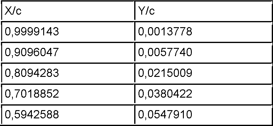

[0053] Los valores X/c e Y/c están normalizados en la profundidad de perfil (c en el divisor de los valores), el origen de las coordenadas está en el borde delantero y los valores se disponen en la tabla de arriba a abajo de tal manera que el punto de partida es el borde trasero, primero a lo largo del lado de presión negativa hacia el borde delantero y a continuación a lo largo del lado de presión positiva de nuevo de vuelta al borde trasero.The X / c and Y / c values are normalized in the profile depth (c in the divisor of the values), the origin of the coordinates is at the leading edge and the values are arranged in the table from top to bottom such that the starting point is the trailing edge, first along the negative pressure side towards the leading edge and then along the positive pressure side again back to the trailing edge.
[0054] Además, es ventajoso que el perfil de sección transversal de la región del perfil principal se forme en coordenadas normalizadas en 1 según la siguiente Tabla 2.Furthermore, it is advantageous that the cross-sectional profile of the main profile region is formed in 1-normalized coordinates according to the following Table 2.
Tabla 2Table 2


[0055] Los valores X/c e Y/c están normalizados en la profundidad de perfil (c en el divisor de los valores), el origen de las coordenadas está en el borde delantero y los valores se disponen en la tabla de arriba a abajo de tal manera que el punto de partida es el borde trasero, primero a lo largo del lado de presión negativa hacia el borde delantero y a continuación a lo largo del lado de presión positiva de nuevo de vuelta al borde trasero.The X / c and Y / c values are normalized in the profile depth (c in the divisor of the values), the origin of the coordinates is at the leading edge and the values are arranged in the table from top to bottom such that the starting point is the trailing edge, first along the negative pressure side towards the leading edge and then along the positive pressure side again back to the trailing edge.
[0056] Además, los valores Y/c de la Tabla 1 pueden proporcionarse con un factor de 0,7 a 1,1, preferiblemente 0,8, y/o los valores Y/c de la Tabla 2 con un factor de 0,7 a 1,1, preferiblemente 0,9. Por lo tanto, las dos tablas, en particular los valores Y/c, se pueden graduar con estos factores.Furthermore, the Y / c values of Table 1 can be provided with a factor of 0.7 to 1.1, preferably 0.8, and / or the Y / c values of Table 2 with a factor of 0 .7 to 1.1, preferably 0.9. Therefore, the two tables, in particular the Y / c values, can be graded with these factors.
[0057] Por medio de estos perfiles de las regiones (región de perfil interior, principal y/o exterior) de la pala de rotor de autogiro diseñados de esta manera, esta puede adaptarse de manera óptima a los requisitos para el comportamiento de vuelo del rotor de autogiro. Si, por ejemplo, se requiere una velocidad de vuelo más alta, el espesor de perfil relativo puede seleccionarse, por ejemplo, menor, con lo que se contrarrestan los efectos transónicos que ocurren a velocidades de vuelo más altas, lo que conduce no solo a una menor resistencia al aire del rotor de autogiro, sino también a una correspondiente reducción de ruido.By means of these profiles of the regions (inner, main and / or outer profile region) of the autogyro rotor blade designed in this way, it can be optimally adapted to the requirements for the flight behavior of the autogyro rotor. If, for example, a higher flight speed is required, the relative profile thickness can be selected, for example, smaller, thereby counteracting the transonic effects that occur at higher flight speeds, leading not only to less air resistance of the autogyro rotor, but also a corresponding reduction in noise.
[0058] Se describen otras ventajas de la invención en los siguientes ejemplos de realización. En el dibujo muestran: Figura 1 una vista en perspectiva de una pala de rotor de autogiro,[0058] Other advantages of the invention are described in the following embodiments. The drawing shows: Figure 1 a perspective view of an autogyro rotor blade,
Figura 2 un diagrama de un trazado de profundidad de perfil y de un trazado del alabeo de una pala de rotor de autogiro,Figure 2 a diagram of a profile depth plot and a roll plot of an autogyro rotor blade,
Figura 3 una sección transversal del perfil de la región del perfil interior yFigure 3 a cross section of the profile of the inner profile region and
Figura 4 una sección transversal del perfil de la región del perfil principal.Figure 4 a cross section of the profile of the main profile region.
[0059] La Figura 1 muestra una vista en perspectiva de una pala 1 de rotor de autogiro. Esta se extiende a lo largo de una dirección longitudinal desde una raíz 2 de pala hasta una punta 3 de pala, que se disponen en los respectivos extremos de la pala 1 de rotor de autogiro. En la región de la raíz 2 de pala, la pala 1 de rotor de autogiro se puede sujetar a un cabezal de rotor de un autogiro. Por lo tanto, la pala 1 de rotor de autogiro rota alrededor del cabezal de rotor durante la operación de vuelo del autogiro, estando la raíz 2 de pala en el interior durante la rotación y la punta 3 de pala en el exterior. Por ello, la punta 3 de pala tiene una velocidad periférica más alta que, por ejemplo, una región más hacia el interior en dirección a la raíz 2 de pala. Una superposición de la velocidad periférica de la pala 1 de rotor de autogiro y un viento aparente da como resultado la velocidad de circulación del aire en la pala 1 de rotor de autogiro. Por ejemplo, en el caso de la pala 1 de rotor de autogiro que va hacia adelante, la velocidad de flujo es mayor hacia el exterior.[0059] Figure 1 shows a perspective view of an autogyro rotor blade 1. This extends along a longitudinal direction from a blade root 2 to a blade tip 3, which are arranged at the respective ends of the autogyro rotor blade 1. In the region of the blade root 2, the autogyro rotor blade 1 can be attached to a rotor head of an autogyro. Therefore, the autogyro rotor blade 1 rotates around the rotor head during the flight operation of the autogyro, the blade root 2 being on the inside during rotation and the blade tip 3 on the outside. Therefore, the blade tip 3 has a higher peripheral velocity than, for example, a region further inward in the direction of the blade root 2. An overlap of the peripheral speed of the gyroplane rotor blade 1 and an apparent wind results in the speed of air circulation in the gyroplane rotor blade 1. For example, in the case of the forward going autogyro rotor blade 1, the flow velocity is higher towards the outside.
[0060] Además, la pala 1 de rotor de autogiro tiene un borde delantero 4 que va por delante durante la operación de vuelo del autogiro, y un borde trasero 5 que va detrás durante la operación de vuelo del autogiro. El borde delantero 4 y el borde trasero 5 bordean la pala 1 de rotor de autogiro, de modo que su borde forma un plano de planta de la pala 1 de rotor de autogiro (véase la Figura 2).[0060] Furthermore, the autogyro rotor blade 1 has a leading edge 4 that goes ahead during the flight operation of the gyroplane, and a trailing edge 5 that goes behind during the flight operation of the autogyro. The leading edge 4 and the trailing edge 5 border the autogyro rotor blade 1, so that their edge forms a floor plan of the autogyro rotor blade 1 (see Figure 2).
[0061] Una sección, en particular una sección de 90°, transversal respecto a la dirección longitudinal designa un perfil 21a-f de la pala 1 de rotor de autogiro. Los perfiles respectivos 21a-f pueden cambiarse en la dirección longitudinal de la pala 1 de rotor de autogiro de modo que los perfiles respectivos 21a-f difieran. Además, los perfiles 21a-f pueden, por ejemplo, cambiarse continuamente, convirtiéndose el primer perfil 21c, por ejemplo, continua y constantemente en el tercer perfil 21d. Además, la pala 1 de rotor de autogiro también puede tener perfiles 21 significativamente más diferentes. Por ejemplo, la pala 1 de rotor de autogiro puede tener un perfil 21 adicional, en particular diferente, entre el primer perfil 21c y el tercer perfil 21d.[0061] A section, in particular a 90 ° section, transverse with respect to the longitudinal direction designates a profile 21a-f of the autogyro rotor blade 1. The respective profiles 21a-f can be changed in the longitudinal direction of the gyroplane rotor blade 1 so that the respective profiles 21a-f differ. Furthermore, the profiles 21a-f can, for example, be continuously changed, with the first profile 21c becoming, for example, continuously and constantly the third profile 21d. Furthermore, the autogyro rotor blade 1 can also have significantly more different profiles 21. For example, the autogyro rotor blade 1 may have an additional profile 21, in particular a different one, between the first profile 21c and the third profile 21d.
[0062] Los perfiles 21a-f en las diversas regiones de la pala 1 de rotor de autogiro determinan en este caso las propiedades de la pala 1 de rotor de autogiro, como por ejemplo la fuerza ascensional y la resistencia al aire.The profiles 21a-f in the various regions of the autogyro rotor blade 1 in this case determine the properties of the autogyro rotor blade 1, such as lift force and air resistance.
[0063] El primer perfil 21c es la sección transversal de una región de perfil interior 9 (véanse las Figuras 2 y 3). El segundo perfil 21e es la sección transversal de una región de perfil principal 10 (véanse las Figuras 2 y 4). The first profile 21c is the cross section of an inner profile region 9 (see Figures 2 and 3). The second profile 21e is the cross section of a main profile region 10 (see Figures 2 and 4).
[0064] Además, la distancia entre el borde delantero 4 y el borde trasero 5 se denomina profundidad de perfil 8. Según la invención, la profundidad de perfil 8 disminuye de forma monotónica desde una región de una profundidad de perfil máxima 15 hacia la punta 3 de pala. Además o como alternativa, la profundidad de perfil 8 también se puede diseñar para que sea constante en una región de la pala 1 de rotor de autogiro. La profundidad de perfil 8 también puede influir en las propiedades de la pala 1 de rotor de autogiro. Por ejemplo, un trazado de profundidad de perfil correspondiente origina un campo de viento descendente más favorable, lo que en última instancia origina una menor resistencia del rotor de autogiro.Furthermore, the distance between the leading edge 4 and the trailing edge 5 is called the profile depth 8. According to the invention, the profile depth 8 decreases monotonic from a region of a maximum profile depth 15 towards the tip. 3 shovel. Additionally or alternatively, the profile depth 8 can also be designed to be constant over a region of the autogyro rotor blade 1. The profile depth 8 can also influence the properties of the autogyro rotor blade 1. For example, a corresponding profile depth plot results in a more favorable downwind field, which ultimately results in less resistance from the autogyro rotor.
[0065] Por lo tanto, los requisitos del autogiro pueden abordarse con una pala 1 de rotor de autogiro que se estrecha hacia el exterior y formas especiales de los perfiles 21a-f. Si, por ejemplo, el autogiro debe transportar cargas mayores, el trazado de profundidad de perfil puede graduarse con un factor que, por ejemplo, aumente la profundidad de perfil local, de modo que se aumente la fuerza ascensional. Este factor puede ser el mismo para cada región de la pala de rotor de autogiro. Además o como alternativa, las regiones individuales, por ejemplo la región del perfil interior, del perfil principal, del perfil exterior y/o la al menos una región de perfil de transición, podrían tener factores diferentes. En este caso, al menos dos factores son diferentes. Asimismo, se pueden formar perfiles 21a-f que tengan una mayor fuerza ascensional. En cambio, si el autogiro debe utilizarse, por ejemplo, para fines deportivos, el trazado de profundidad de perfil se puede reducir con un factor que, por ejemplo, reduzca la profundidad de perfil local de modo que el trazado de profundidad de perfil se pueda adaptar idealmente a cada radio de rotor de autogiro, y así se reduzca la resistencia al aire y, de este modo, se pueda lograr una mayor velocidad de vuelo con el autogiro. Por lo tanto, el rendimiento de vuelo de la pala 1 de rotor de autogiro en general puede aumentarse y adaptarse a los requisitos del autogiro.Therefore, the requirements of the autogyro can be addressed with an outwardly tapering autogyro rotor blade 1 and special shapes of the profiles 21a-f. If, for example, the gyroplane must carry higher loads, the profile depth plot can be graduated by a factor that, for example, increases the local profile depth, so that lift force is increased. This factor can be the same for each region of the gyroplane rotor blade. Additionally or alternatively, the individual regions, for example the inner profile region, the main profile, the outer profile and / or the at least one transition profile region, could have different factors. In this case, at least two factors are different. Also, profiles 21a-f having a higher lift can be formed. On the other hand, if the gyroplane is to be used, for example, for sporting purposes, the profile depth plot can be reduced by a factor that, for example, reduces the local profile depth so that the profile depth plot can be ideally adapted to each gyrocopter rotor radius, thereby reducing air resistance and thus achieving higher flight speed with the gyrocopter. Therefore, the flight performance of the autogyro rotor blade 1 in general can be increased and adapted to the requirements of the autogyro.
[0066] La distancia transversal respecto a la dirección longitudinal, en particular 90° respecto a la dirección longitudinal, de la pala 1 de rotor de autogiro entre el borde delantero 4 y el borde trasero 5 se denomina profundidad de perfil 8. La profundidad de perfil 8 disminuye desde una región de una profundidad de perfil máxima 15 hacia la punta 3 de pala. Con una profundidad de perfil 8 decreciente, puede generarse un campo de viento descendente más favorable, por lo que se forman menos remolinos y se reduce la resistencia al aire. Con la reducción de la profundidad de perfil 8 hacia el exterior, se reduce la resistencia al aire del rotor de autogiro, lo que es ventajoso para el rendimiento de vuelo del autogiro.The transverse distance from the longitudinal direction, in particular 90 ° from the longitudinal direction, of the autogyro rotor blade 1 between the leading edge 4 and the trailing edge 5 is called the profile depth 8. The depth of profile 8 tapers from a region of maximum profile depth 15 towards blade tip 3. With a decreasing profile depth 8, a more favorable downwind field can be generated, whereby fewer eddies are formed and air resistance is reduced. With the reduction of the profile depth 8 outwards, the air resistance of the gyrocopter rotor is reduced, which is advantageous for the flight performance of the gyrocopter.
[0067] La Figura 2 muestra un diagrama de un trazado de profundidad de perfil 22 y de un trazado del alabeo 23 de una pala 1 de rotor de autogiro. La extensión longitudinal 14 de la pala 1 de rotor de autogiro se aplica en el eje de abscisas u horizontal. En este caso, la raíz 2 de pala está dispuesta en el lado izquierdo y la punta 3 de pala en el lado derecho del eje de abscisas. Por lo tanto, la pala 1 de rotor de autogiro se extiende en una dirección de coordenadas positiva desde la raíz 2 de pala hacia la punta 3 de pala. En el eje de ordenadas o vertical, por un lado se aplica la profundidad de perfil 8, y por otro lado el alabeo de la pala 1 de rotor de autogiro o el ángulo de alabeo a. Los dos gráficos reproducen así el trazado de profundidad de perfil 22 y el trazado del alabeo 23.[0067] Figure 2 shows a diagram of a profile depth plot 22 and a roll plot 23 of an autogyro rotor blade 1. The longitudinal extension 14 of the autogyro rotor blade 1 is applied on the abscissa or horizontal axis. In this case, the spade root 2 is arranged on the left side and the spade point 3 on the right side of the abscissa axis. Therefore, the autogyro rotor blade 1 extends in a positive coordinate direction from the blade root 2 towards the blade tip 3. On the vertical or ordinate axis, on the one hand the profile depth 8 is applied, and on the other hand the warping of the autogyro rotor blade 1 or the warping angle a. The two graphs thus reproduce the profile depth plot 22 and the roll plot 23.
[0068] La pala 1 de rotor de autogiro se divide, además, en diferentes regiones de perfil 9, 10, 11, 12. Se dispone una región de perfil interior 9 en la raíz 2 de pala y/o adyacente a esta. Se dispone una región de perfil exterior 11 en la punta 3 de pala y/o adyacente a esta. Se dispone una región de perfil principal 10 entre estas regiones de perfil 9, 11. Las tres regiones de perfil 9, 10, 11 pueden tener en este caso diferentes perfiles. En este caso, un perfil es una sección, en particular una sección de 90°, hacia la dirección longitudinal de la pala 1 de rotor de autogiro. Por ejemplo, la región del perfil interior 9 podría tener un perfil, en particular el primer perfil 21c de la Figura 1, según la Tabla 1 contenida en la descripción anterior o según la Figura 3. La región del perfil principal 10 podría, por ejemplo, tener un perfil, en particular el segundo perfil 21e de la Figura 1, según la Tabla 2 contenida en la descripción anterior o según la Figura 4.[0068] The autogyro rotor blade 1 is further divided into different profile regions 9, 10, 11, 12. An inner profile region 9 is arranged at the blade root 2 and / or adjacent to it. An outer profile region 11 is provided at and / or adjacent to the blade tip 3. A main profile region 10 is arranged between these profile regions 9, 11. The three profile regions 9, 10, 11 may in this case have different profiles. In this case, a profile is a section, in particular a 90 ° section, towards the longitudinal direction of the autogyro rotor blade 1. For example, the region of the inner profile 9 could have a profile, in particular the first profile 21c of Figure 1, according to Table 1 contained in the previous description or according to Figure 3. The region of the main profile 10 could, for example , have a profile, in particular the second profile 21e of Figure 1, according to Table 2 contained in the previous description or according to Figure 4.
[0069] Además, se dispone una región de perfil de transición 12 entre la región del perfil interior 9 y la región del perfil principal 10. Además, también se puede disponer una segunda región de perfil de transición entre la región del perfil principal 10 y la región del perfil exterior 11. En particular, la región del perfil interior 9 así como la región del perfil principal 10 tienen perfiles 21c, 21e diferentes. Se puede formar una transición entre los diversos perfiles mediante la región del perfil de transición 12.Furthermore, a transition profile region 12 is provided between the inner profile region 9 and the main profile region 10. In addition, a second transition profile region may also be provided between the main profile region 10 and the outer profile region 11. In particular, the inner profile region 9 as well as the main profile region 10 have different profiles 21c, 21e. A transition can be formed between the various profiles by the transition profile region 12.
[0070] Un alabeo en la pala 1 de rotor de autogiro es un retorcimiento de la misma alrededor de un eje en dirección longitudinal. El borde delantero 4 y el borde trasero 5 (véase la Figura 1) describen en un alabeo una hélice alrededor del eje en dirección longitudinal. En particular, el borde delantero 4 se hace girar desde la raíz 2 de pala hasta la punta 3 de pala en dirección al lado de presión positiva 7 y el borde trasero 5 en dirección al lado de presión negativa 6 (para el lado de presión positiva 7 y el lado de presión negativa 6 véanse las Figuras 3, 4). Durante el funcionamiento normal de vuelo del autogiro, la pala 1 de rotor de autogiro tiene, por tanto, un ángulo con respecto a un plano de rotación del rotor de autogiro mayor en la raíz 2 de pala que en la punta 3 de pala. Este ángulo mayor en la raíz 2 de pala también se refleja de nuevo en que el borde delantero 4 está a una distancia mayor con respecto a este plano de rotación que el borde trasero 5. En la punta 3 de pala, esta diferencia en las distancias del borde delantero 4 o del borde trasero 5 con respecto al plano de rotación es menor debido al alabeo. Esto conduce a una menor resistencia al aire de la pala 1 de rotor de autogiro. [0070] A warpage in the autogyro rotor blade 1 is a twisting thereof about an axis in the longitudinal direction. The leading edge 4 and the trailing edge 5 (see Figure 1) warp a helix around the axis in the longitudinal direction. In particular, the leading edge 4 is rotated from the blade root 2 to the blade tip 3 in the direction of the positive pressure side 7 and the rear edge 5 in the direction of the negative pressure side 6 (for the positive pressure side 7 and negative pressure side 6 see Figures 3, 4). During normal flight operation of the autogyro, the autogyro rotor blade 1 therefore has a greater angle with respect to a plane of rotation of the autogyro rotor at the blade root 2 than at the blade tip 3. This greater angle at the blade root 2 is also reflected again in that the leading edge 4 is at a greater distance from this plane of rotation than the trailing edge 5. At the blade tip 3, this difference in distances of the leading edge 4 or the trailing edge 5 with respect to the plane of rotation is less due to warping. This leads to less air resistance of the autogyro rotor blade 1.
[0071] Además, por ejemplo, una sección en el eje de ordenadas izquierdo 16, que indica la profundidad de perfil 8 de la pala 1 de rotor de autogiro, podría ser el 20% de la profundidad de perfil máxima. Por lo tanto, el eje de ordenadas izquierdo se extendería más del 120% (del 0% al 120%). Una sección del eje de ordenadas derecho 17, que indica el alabeo, podría ser, por ejemplo, 1°. Además, el eje de ordenadas derecho podría llegar de -1° a 5°. Una sección en el eje de abscisas 18 podría ascender al 10% de la extensión longitudinal 14, por lo tanto la pala 1 de rotor de autogiro se extiende del 0% al 100% de la extensión longitudinal 14, con lo que se normaliza en la extensión longitudinal 14.Furthermore, for example, a section on the left ordinate 16, indicating the profile depth 8 of the autogyro rotor blade 1, could be 20% of the maximum profile depth. Therefore, the left ordinate would extend more than 120% (0% to 120%). A section of the right ordinate axis 17, indicating warping, could be, for example, 1 °. Also, the right ordinate axis could go from -1 ° to 5 °. A section on the abscissa axis 18 could amount to 10% of the longitudinal extension 14, therefore the autogyro rotor blade 1 extends from 0% to 100% of the longitudinal extension 14, thereby normalizing in the longitudinal extension 14.
[0072] Cabe señalar aquí que, aunque la región delante de la región del perfil interior 9 del 0% al 16% todavía pertenece a la pala 1 de rotor de autogiro, aquí, por ejemplo, los medios de sujeción están dispuestos y forman una transición a la región del perfil interior. Por esta razón, el trazado de profundidad de perfil 22 y el trazado del alabeo 23 tienen un valor constante y aumentan rápidamente en la transición a la región del perfil interior 9. Sin embargo, esta región debe excluirse al considerar la función de la pala 1 de rotor de autogiro. Por ello, la extensión longitudinal 14 y la consideración de la función de la pala 1 de autogiro solo empiezan en el 16% y terminan cerca del 100%.It should be noted here that, although the region in front of the region of the inner profile 9 from 0% to 16% still belongs to the autogyro rotor blade 1, here, for example, the clamping means are arranged and form a transition to the inner profile region. For this reason, the profile depth plot 22 and the warp plot 23 have a constant value and increase rapidly in the transition to the inner profile region 9. However, this region should be excluded when considering the blade 1 function. of autogyro rotor. Therefore, the longitudinal extension 14 and the consideration of the function of the autogyro blade 1 only start at 16% and end close to 100%.
[0073] Además, la pala 1 de rotor de autogiro se divide en diferentes regiones de perfil 9, 10, 11, 12. Se dispone la región de perfil interior 9 en la raíz 2 de pala y/o adyacente a esta. A continuación de esta se dispone la región del perfil de transición 12. De nuevo a continuación de esta se dispone la región del perfil principal 10. Finalmente, la pala 1 de rotor de autogiro tiene la región del perfil exterior 11. Además o como alternativa, se puede disponer una segunda región de perfil de transición entre la región del perfil principal 10 y la región del perfil exterior 11.Furthermore, the autogyro rotor blade 1 is divided into different profile regions 9, 10, 11, 12. The inner profile region 9 is arranged at the blade root 2 and / or adjacent to it. This is followed by the transition profile region 12. Again following this is the main profile region 10. Finally, the autogyro rotor blade 1 has the outer profile region 11. In addition or as an alternative , a second transition profile region may be provided between the main profile region 10 and the outer profile region 11.
[0074] En este ejemplo de realización, la región del perfil interior 9 se extiende en un intervalo del 16% al 34% de la extensión longitudinal de la pala 1 de rotor de autogiro. La profundidad de perfil 8 se puede leer, por ejemplo, mediante el trazado de profundidad de perfil 22 para la región del perfil interior 9, y tiene, por ejemplo, valores de aproximadamente el 100% hasta el 90% de la profundidad de perfil máxima. La distancia entre el borde delantero 4 y el borde trasero 5 es, por lo tanto, estos valores de la profundidad de perfil máxima en esta región. El trazado de profundidad de perfil 22 disminuye de forma monotónica desde una región de la profundidad de perfil máxima 15 de la pala 1 de rotor de autogiro. Además o como alternativa, el trazado de profundidad de perfil 22 también se puede diseñar para que sea constante en una región de la extensión longitudinal 14. El trazado del alabeo 23 también disminuye de forma monotónica en esta región del perfil interior 9. En este caso, el alabeo en esta región está entre aproximadamente 4,5° y 2,8°, como se puede leer mediante el trazado del alabeo 23. En una sección de aproximadamente el 16% al 34% de la extensión longitudinal 14, el trazado del alabeo 23 es cóncavo, por ejemplo, parabólico y/o exponencialmente descendente.In this exemplary embodiment, the region of the inner profile 9 extends in a range from 16% to 34% of the longitudinal extension of the rotor blade 1 of the autogyro. The profile depth 8 can be read, for example, by the profile depth plot 22 for the inner profile region 9, and has, for example, values from about 100% to 90% of the maximum profile depth . The distance between the leading edge 4 and the trailing edge 5 is therefore these values of the maximum profile depth in this region. The profile depth trace 22 decreases monotonic from a region of the maximum profile depth 15 of the autogyro rotor blade 1. In addition or alternatively, the profile depth trace 22 can also be designed to be constant over a region of the longitudinal extent 14. The warp trace 23 also decreases monotonic in this region of the inner profile 9. In this case , the roll in this region is between approximately 4.5 ° and 2.8 °, as can be read by plotting the roll 23. In a section of approximately 16% to 34% of the longitudinal extent 14, the plot of the warping 23 is concave, eg, parabolic and / or exponentially descending.
[0075] Por ejemplo, la región del perfil de transición 12 puede extenderse del 35% al 50% de la extensión longitudinal 14. Aquí, el trazado de profundidad de perfil 22 es más o menos constante. El trazado del alabeo 23 disminuye linealmente o tiene una inclinación constante (negativa). Por ejemplo, el ángulo de alabeo a disminuye del 2,8° al 0,8°.For example, the transition profile region 12 may extend from 35% to 50% of the longitudinal extent 14. Here, the profile depth plot 22 is more or less constant. The course of the roll 23 decreases linearly or has a constant (negative) slope. For example, the bank angle a decreases from 2.8 ° to 0.8 °.
[0076] Por ejemplo, la región del perfil principal 10 se extiende del 50% al 96% de la extensión longitudinal 14 de la pala 1 de rotor de autogiro. En esta región, el trazado de profundidad de perfil 22 continúa disminuyendo de forma monotónica. En una primera sección de esta región, de aproximadamente el 50% al 64% de la extensión longitudinal 14, el trazado de profundidad del perfil 22 disminuye solo ligeramente de, por ejemplo, el 87% al 82%. Del 64% al 96%, el trazado de profundidad de perfil 22 disminuye en mayor medida, de un valor de por ejemplo el 82% al 42%.[0076] For example, the region of the main profile 10 extends from 50% to 96% of the longitudinal extension 14 of the autogyro rotor blade 1. In this region, the profile depth plot 22 continues to decrease monotonic. In a first section of this region, from about 50% to 64% of the longitudinal extent 14, the depth trace of the profile 22 decreases only slightly from, for example, 87% to 82%. From 64% to 96%, the profile depth plot 22 decreases to a greater extent, from a value of for example 82% to 42%.
[0077] El plano de planta de la pala 1 de rotor de autogiro disminuye de forma monotónica desde la raíz 2 de pala hacia la punta 3 de pala con una profundidad de perfil máxima 15 y tiene las profundidades de perfil enumeradas en la siguiente Tabla 3 en las posiciones de radio enumeradas. La profundidad de perfil máxima 15 está normalizada en el 100%. Todos los demás valores enumerados en la Tabla 3 se refieren a esta profundidad de perfil máxima. La profundidad de perfil 8 disminuye a partir de una profundidad de perfil máxima en dirección a la punta 3 de pala de modo que, por ejemplo, en el 60% del radio la profundidad de perfil 8 sigue siendo el 85% de la profundidad de perfil máxima. Entre las posiciones de radio, el plano de planta tiene transiciones uniformes y/o se extiende arqueado. Además, la profundidad de perfil 8 se puede graduar con un factor de 0,8 a 1,2 con el fin de adaptar idealmente el plano de planta para los respectivos objetivos de diseño:[0077] The ground plane of the autogyro rotor blade 1 decreases monotonic from the blade root 2 towards the blade tip 3 with a maximum profile depth 15 and has the profile depths listed in the following Table 3 at the radio positions listed. The maximum profile depth 15 is normalized at 100%. All other values listed in Table 3 refer to this maximum profile depth. The profile depth 8 decreases from a maximum profile depth in the direction of the blade tip 3 so that, for example, at 60% of the radius the profile depth 8 remains 85% of the profile depth maximum. Between radius positions, the floor plan has smooth transitions and / or extends arched. In addition, the profile depth 8 can be graduated by a factor of 0.8 to 1.2 in order to ideally adapt the floor plan for the respective design goals:
Tabla 3Table 3


[0078] El trazado del alabeo 23 también disminuye en la región del perfil principal 10. El valor del trazado del alabeo 23 disminuye, por ejemplo, de 0,8° a -0,5° y tiene, por ejemplo, un trazado descendente de forma parabólica, polinómica y/o exponencial.[0078] The roll track 23 also decreases in the region of the main profile 10. The roll track value 23 decreases, for example, from 0.8 ° to -0.5 ° and has, for example, a downward track in parabolic, polynomial and / or exponential form.
[0079] Además, la región del perfil principal 10 tiene, en el lado de la raíz, una primera subregión 24 en la que el trazado del alabeo 23 tiene valores positivos, en particular ángulos de alabeo a positivos. Además, la región del perfil principal 10 tiene, en el lado de la punta, una segunda subregión 25 en la que el trazado del alabeo 23 tiene valores negativos, en particular ángulos de alabeo a negativos. Entre la primera subregión 24 y la segunda subregión 25 tiene lugar un cambio de signo 28 del trazado del alabeo 23 que está dispuesto en aproximadamente el 70% de la dirección longitudinal de la pala 1 de rotor de autogiro. En un ángulo de ataque de cero grados, el perfil se dispone paralelo al plano de giro de la pala 1 de rotor de autogiro rotatoria en el punto del cambio de signo 28. En la primera subregión 24, el ángulo de ataque geométrico local aumenta por el alabeo. En cambio, en la segunda subregión 25 el ángulo de ataque geométrico se reduce. Estos cambios en el ángulo de ataque geométrico provocan una distribución de viento descendente más favorable de modo que se producen menos remolinos en la estela, por lo que el rotor de autogiro autorrota más fácilmente, lo que conlleva una menor resistencia del rotor de autogiro.Furthermore, the main profile region 10 has, on the root side, a first sub-region 24 in which the roll path 23 has positive values, in particular positive roll angles. Furthermore, the main profile region 10 has, on the tip side, a second sub-region 25 in which the roll path 23 has negative values, in particular negative roll angles. Between the first subregion 24 and the second subregion 25 a change of sign 28 of the course of the roll 23 takes place which is arranged in approximately 70% of the longitudinal direction of the autogyro rotor blade 1. At a zero degree angle of attack, the profile is arranged parallel to the plane of rotation of the rotating autogyro rotor blade 1 at the point of sign change 28. In the first sub-region 24, the local geometric angle of attack increases by warping. In contrast, in the second subregion 25 the geometric angle of attack is reduced. These changes in the geometric angle of attack result in a more favorable downwind distribution so that fewer eddies occur in the wake, thus the autogyro rotor autorotats more easily, resulting in less resistance of the autogyro rotor.
[0080] Entre el 96% y el 100% de la extensión longitudinal 14 de la pala 1 de rotor de autogiro se puede disponer la región del perfil exterior 11, que completa la pala 1 de rotor de autogiro. Aquí, el trazado de profundidad del perfil 22 disminuye de forma parabólica, convexa, polinómica y/o no lineal en el 42% y va hacia cero. El trazado del alabeo 23 permanece esencialmente constante en esta región.[0080] Between 96% and 100% of the longitudinal extension 14 of the autogyro rotor blade 1, the region of the outer profile 11 can be provided, which completes the autogyro rotor blade 1. Here, the depth plot of profile 22 decreases in a parabolic, convex, polynomial, and / or nonlinear fashion by 42% and goes toward zero. The course of roll 23 remains essentially constant in this region.
[0081] Una pala 1 de rotor de autogiro con este trazado de profundidad de perfil 22 y este trazado del alabeo 23 puede ajustarse a los requisitos de vuelo especiales. Por ejemplo, esta pala 1 de rotor de autogiro puede permitir una alta velocidad de vuelo del autogiro, ya que la resistencia al aire es particularmente baja.[0081] An autogyro rotor blade 1 with this profile depth plot 22 and this roll plot 23 can be adjusted to special flight requirements. For example, this autogyro rotor blade 1 can allow a high speed of flight of the autogyro, since the air resistance is particularly low.
[0082] El trazado de profundidad de perfil 22 se forma en la región del perfil de transición 12 y/o en la región del perfil principal 10 como una curva arqueada y/o descendente de forma monotónica. El trazado de profundidad de perfil 22 también se puede determinar mediante una curva descendente de forma estrictamente monotónica.The profile depth trace 22 is formed in the transition profile region 12 and / or in the main profile region 10 as a monotonic arcuate and / or descending curve. The profile depth plot 22 can also be determined by a strictly monotonic downward curve.
[0083] Además, el trazado del alabeo 23 tiene una primera curvatura 26 entre la región del perfil interior 9 y la región del perfil de transición 12 y una segunda curvatura 27 entre la región del perfil de transición 12 y la región del perfil principal 10.In addition, the warping path 23 has a first curvature 26 between the inner profile region 9 and the transition profile region 12 and a second curvature 27 between the transition profile region 12 and the main profile region 10 .
[0084] Además, la inclinación del trazado del alabeo 23 en la región del perfil de transición 12 es al menos la mitad de grande que en la región del perfil interior 9 y/o la región del perfil principal 10. Además, el alabeo total en la región del perfil de transición 12 es al menos la mitad de grande que el alabeo total en la región del perfil interior 9 y/o la región del perfil principal 10. En este caso, una diferencia entre el trazado del alabeo 23 al principio y al final de una región debe definirse como alabeo total en una región. Por ejemplo, el alabeo total en la región del perfil de transición 12 es de aproximadamente 2,0° (2,8° - 0,8°).[0084] Furthermore, the slope of the roll path 23 in the transition profile region 12 is at least half as large as that in the inner profile region 9 and / or the main profile region 10. Furthermore, the total roll in the region of the transition profile 12 is at least half as large as the total warpage in the region of the inner profile 9 and / or the region of the main profile 10. In this case, a difference between the course of the warp 23 at the beginning and the end of a region must be defined as total warpage in a region. For example, the total warpage in the transition profile region 12 is approximately 2.0 ° (2.8 ° - 0.8 °).
[0085] La Figura 3 muestra una sección transversal del perfil de la región del perfil interior 9 (véase la Figura 2). En este caso, la Figura 3 es la representación gráfica de la Tabla 1 de la descripción anterior. El perfil de la región del perfil interior 9 está delimitado por el borde delantero 4, el borde trasero 5, un lado de presión negativa 6 así como el lado de presión positiva 7. El lado de presión negativa 6 está arqueado mucho más que el lado de presión positiva 7, de modo que el efecto de desplazamiento del perfil provoca una aceleración del flujo de aire que fluye alrededor, por lo que se regula la distribución de presión correspondiente según la ley de Bernoulli. Esto provocará una presión menor en el lado de presión negativa que en el lado de presión positiva. Esto produce una fuerza en la dirección del lado de presión negativa 6 que genera la fuerza ascensional.[0085] Figure 3 shows a cross section of the profile of the inner profile region 9 (see Figure 2). In this case, Figure 3 is the graphical representation of Table 1 of the previous description. The profile of the inner profile region 9 is delimited by the leading edge 4, the trailing edge 5, a negative pressure side 6 as well as the positive pressure side 7. The negative pressure side 6 is arcuate much more than the side of positive pressure 7, so that the effect of displacement of the profile causes an acceleration of the air flow that flows around, whereby the corresponding pressure distribution is regulated according to Bernoulli's law. This will cause a lower pressure on the negative pressure side than on the positive pressure side. This produces a force in the direction of the negative pressure side 6 that generates the lifting force.
[0086] La profundidad de perfil 8 está normalizada en 1 en esta Figura 3, en donde el borde delantero 4 puede disponerse en el sistema de coordenadas en 0 y el borde trasero 5 en 1. Los valores X/c e Y/c contenidos en las Tablas 1, 2 son, en este caso, las coordenadas X e Y correspondientes del sistema de coordenadas, en donde c se encuentra en el denominador para la profundidad de perfil 8 (con el fin de normalizar las coordenadas).The profile depth 8 is normalized to 1 in this Figure 3, where the leading edge 4 can be arranged in the coordinate system at 0 and the trailing edge 5 at 1. The X / c and Y / c values contained in Tables 1, 2 are, in this case, the corresponding X and Y coordinates of the coordinate system, where c is in the denominator for profile depth 8 (in order to normalize the coordinates).
[0087] El espesor de perfil 19 también está normalizado en la profundidad de perfil 8. Un espesor de perfil relativo de la pala 1 de rotor de autogiro se define como la relación entre el mayor espesor de perfil 20a y la profundidad de perfil 8. Por ejemplo, en el caso de una distribución de espesor relativo, el espesor de perfil relativo de la región del perfil interior 9 está entre el 25% y el 35%, y asciende entre el 11% y el 15%, preferiblemente el 13,5%. En este caso, la distribución de espesor relativo es la relación de la distancia del mayor espesor de perfil 20a del borde delantero 4 y la profundidad de perfil 8. En este ejemplo de realización, el espesor relativo 20a se dispone en el 29,2%.The profile thickness 19 is also normalized at the profile depth 8. A relative profile thickness of the autogyro rotor blade 1 is defined as the ratio between the greatest profile thickness 20a and the profile depth 8. For example, in the case of a relative thickness distribution, the relative profile thickness of the inner profile region 9 is between 25% and 35%, and is between 11% and 15%, preferably 13, 5%. In this In this case, the relative thickness distribution is the ratio of the distance of the greatest profile thickness 20a from the leading edge 4 and the profile depth 8. In this embodiment, the relative thickness 20a is set at 29.2%.
[0088] Además, el perfil de la región del perfil interior 9 tiene un arqueo máximo entre el 3% y el 4%, en particular entre el 3,6% y el 3,8%, en caso de una distribución de arqueo entre el 30% y el 40%, en particular el 35,3%. En este caso, el arqueo máximo es la relación de la distancia mayor entre la cuerda del perfil y la línea de curvatura media. La cuerda del perfil es la línea de conexión entre el borde delantero 4 y el borde trasero 5. La línea de curvatura media está en medio entre el lado de presión negativa 6 y el lado de presión positiva 7.Furthermore, the profile of the inner profile region 9 has a maximum bow between 3% and 4%, in particular between 3.6% and 3.8%, in case of a bow distribution between 30% and 40%, in particular 35.3%. In this case, the maximum bow is the ratio of the greatest distance between the chord of the profile and the mean curvature line. The chord of the profile is the connecting line between the leading edge 4 and the trailing edge 5. The middle curvature line is in the middle between the negative pressure side 6 and the positive pressure side 7.
[0089] Por ejemplo, si la pala 1 de rotor de autogiro tiene un espesor de perfil 19 mayor, aumenta la fuerza ascensional. Con este perfil, por ejemplo, se puede transportar una carga mayor con el autogiro.[0089] For example, if the autogyro rotor blade 1 has a greater profile thickness 19, the lift force increases. With this profile, for example, a larger load can be transported with the gyroplane.
[0090] En cambio, si el espesor de perfil 19 es menor, se reduce la resistencia al aire de la pala 1 de rotor de autogiro. Entonces se puede lograr, por ejemplo, una mayor velocidad de vuelo y/o un mayor alcance con el autogiro, de modo que el autogiro se pueda utilizar con fines deportivos.[0090] On the other hand, if the profile thickness 19 is less, the air resistance of the autogyro rotor blade 1 is reduced. Then, for example, a higher flight speed and / or a greater range can be achieved with the gyroplane, so that the gyrocopter can be used for sporting purposes.
[0091] La Figura 4 muestra una sección transversal del perfil de la región del perfil principal 10. En este caso, la Figura 4 es la representación gráfica de la Tabla 2 de la descripción anterior. Aquí, además, solo deben abordarse las diferencias con respecto a la anterior Figura 3. El perfil de la región del perfil principal 10 tiene un espesor de perfil relativo entre el 10% y el 14%, preferiblemente del 12,1%, con una distribución de espesor relativo entre el 26% y el 36%, preferiblemente del 29,2%. El perfil tiene un mayor espesor de perfil 20b. Además, el perfil de la región del perfil principal 10 tiene un arqueo máximo entre el 3% y el 4%, en particular entre el 3,2 % y el 3,4%, con una distribución de arqueo relativo entre el 30% y el 40%, preferiblemente cerca del 36,8%.[0091] Figure 4 shows a cross section of the profile of the main profile region 10. In this case, Figure 4 is the graphical representation of Table 2 of the above description. Here, furthermore, only the differences with respect to the previous figure should be addressed. Figure 3. The profile of the main profile region 10 has a relative profile thickness between 10% and 14%, preferably 12.1%, with a relative thickness distribution between 26% and 36%, preferably 29.2%. The profile has a thicker profile 20b. Furthermore, the profile of the main profile region 10 has a maximum tonnage between 3% and 4%, in particular between 3.2% and 3.4%, with a relative tonnage distribution between 30% and 40%, preferably about 36.8%.
[0092] La presente invención no se limita a los ejemplos de realización representados y descritos. También son posibles variaciones en el marco de las reivindicaciones, al igual que una combinación de las características, incluso si se representan y describen en distintos ejemplos de realización.The present invention is not limited to the illustrated and described embodiments. Variations within the framework of the claims are also possible, as is a combination of the characteristics, even if they are represented and described in different embodiments.
Lista de números de referenciaReference number list
[0093][0093]
1 pala de rotor de autogiro1 autogyro rotor blade
2 raíz de pala2 shovel root
3 punta de pala3 spade point
4 borde delantero4 leading edge
5 borde trasero5 rear edge
6 lado de presión negativa6 negative pressure side
7 lado de presión positiva7 positive pressure side
8 profundidad de perfil8 profile depth
9 región del perfil interior9 inner profile region
10 región del perfil principal10 main profile region
11 región del perfil exterior11 outer profile region
12 región del perfil de transición12 transition profile region
14 extensión longitudinal14 longitudinal extension
15 región de profundidad de perfil máxima15 maximum profile depth region
16 sección del eje de ordenadas izquierdo16 left ordinate axis section
17 sección del eje de ordenadas derecho17 right ordinate axis section
18 sección del eje de abscisas18 section of the abscissa axis
19 espesor de perfil19 profile thickness
20 mayor espesor de perfil20 thicker profile
21a perfil21st profile
21b perfil21b profile
21c primer perfil21c first profile
21d tercer perfil21d third profile
21e segundo perfil21e second profile
21f perfil21f profile
22 trazado de profundidad de perfil22 profile depth plot
23 trazado del alabeo23 roll layout
24 primera subregión24 first sub-region
25 segunda subregión25 second sub-region
26 primera curvatura26 first bend
27 segunda curvatura 27 second bend
28 cambio de signo a ángulo de alabeo 28 sign change to bank angle
Claims (13)


Applications Claiming Priority (2)
| Application Number | Priority Date | Filing Date | Title |
|---|---|---|---|
| DE102015121502.0A DE102015121502B4 (en) | 2015-12-10 | 2015-12-10 | gyroplane rotor blade for autorotatory lift generation |
| PCT/EP2016/079520 WO2017097669A1 (en) | 2015-12-10 | 2016-12-02 | Autogyro rotor blade |
Publications (1)
| Publication Number | Publication Date |
|---|---|
| ES2807750T3 true ES2807750T3 (en) | 2021-02-24 |
Family
ID=57542980
Family Applications (1)
| Application Number | Title | Priority Date | Filing Date |
|---|---|---|---|
| ES16809685T Active ES2807750T3 (en) | 2015-12-10 | 2016-12-02 | Autogyro rotor blade |
Country Status (15)
| Country | Link |
|---|---|
| US (1) | US11338913B2 (en) |
| EP (1) | EP3386854B1 (en) |
| JP (1) | JP6899841B2 (en) |
| CN (1) | CN108698687B (en) |
| AU (1) | AU2016365585B2 (en) |
| BR (1) | BR112018011610B1 (en) |
| DE (1) | DE102015121502B4 (en) |
| ES (1) | ES2807750T3 (en) |
| IL (1) | IL259885B2 (en) |
| MX (1) | MX2018006942A (en) |
| PH (1) | PH12018501230B1 (en) |
| PL (1) | PL3386854T3 (en) |
| RU (1) | RU2729115C2 (en) |
| WO (1) | WO2017097669A1 (en) |
| ZA (1) | ZA201803848B (en) |
Families Citing this family (2)
| Publication number | Priority date | Publication date | Assignee | Title |
|---|---|---|---|---|
| CN109229364B (en) * | 2018-10-23 | 2019-06-11 | 西北工业大学 | An elliptical-like airfoil used in the regurgitation region of a high-speed helicopter rotor |
| CN112429217A (en) * | 2020-11-26 | 2021-03-02 | 广东国士健科技发展有限公司 | Aircraft with double-layer rotor wing structure |
Family Cites Families (22)
| Publication number | Priority date | Publication date | Assignee | Title |
|---|---|---|---|---|
| DE506701C (en) * | 1930-09-08 | Cierva Autogiro Co Ltd | Airplane with freely rotating wings driven by the airstream | |
| DE502860C (en) * | 1928-10-27 | 1930-07-19 | Cierva Autogiro Co Ltd | Airplane with freely rotating wings |
| GB452366A (en) | 1935-01-16 | 1936-08-17 | Cierva Juan De La | Improvements in and relating to aircraft with autorotative wings |
| US2247034A (en) * | 1938-12-22 | 1941-06-24 | Autogiro Co Of America | Aircraft sustaining rotor |
| US2272439A (en) * | 1939-12-16 | 1942-02-10 | Autogiro Co Of America | Aircraft sustaining rotor blade |
| US2477113A (en) * | 1942-02-19 | 1949-07-26 | Autogiro Co Of America | Rotor blade for rotative winged aircraft |
| US2447113A (en) | 1947-05-05 | 1948-08-17 | Nat Cylinder Gas Co | Holding mechanism for welding stud ferrules |
| US2917255A (en) * | 1958-08-01 | 1959-12-15 | William Hunter A Boyd | Self-regulating rotochute |
| FR1369600A (en) | 1963-07-23 | 1964-08-14 | Electric Auto Lite Co | Propeller, especially for vertical take-off and landing airplanes |
| CA988906A (en) | 1973-06-04 | 1976-05-11 | United Aircraft Corporation | Helicopter blade |
| ES525921A0 (en) * | 1983-09-26 | 1984-08-01 | Pilar Banolas De Ayala M | IMPROVEMENTS IN SUPPORT PROPELLERS FOR AIRCRAFT |
| FR2689852B1 (en) * | 1992-04-09 | 1994-06-17 | Eurocopter France | BLADE FOR AIRCRAFT TURNING WING, AT THE ARROW END. |
| US5727754A (en) * | 1995-08-31 | 1998-03-17 | Cartercopters, L.L.C. | Gyroplane |
| US6641365B2 (en) | 1998-02-20 | 2003-11-04 | Abraham E. Karem | Optimum speed tilt rotor |
| US6007298A (en) | 1998-02-20 | 1999-12-28 | Karem; Abraham E. | Optimum speed rotor |
| US6497385B1 (en) | 2000-11-08 | 2002-12-24 | Continuum Dynamics, Inc. | Rotor blade with optimized twist distribution |
| US7252479B2 (en) | 2005-05-31 | 2007-08-07 | Sikorsky Aircraft Corporation | Rotor blade for a high speed rotary-wing aircraft |
| US8128376B2 (en) * | 2005-08-15 | 2012-03-06 | Abe Karem | High performance outboard section for rotor blades |
| US7857598B2 (en) | 2006-06-26 | 2010-12-28 | Aerovel Corporation | Variable-twist rotor blade controlled by hub pitch angle and rotational speed |
| US8403255B2 (en) | 2009-08-14 | 2013-03-26 | Frederick W. Piasecki | Compound aircraft with autorotation |
| RU97111U1 (en) | 2010-03-31 | 2010-08-27 | Юрий Петрович Андреев | BLADE |
| US8862310B2 (en) | 2012-06-06 | 2014-10-14 | Simmonds Precision Products, Inc. | Determining rotorcraft collective adjustment during ground test |
-
2015
- 2015-12-10 DE DE102015121502.0A patent/DE102015121502B4/en active Active
-
2016
- 2016-12-02 US US15/781,335 patent/US11338913B2/en active Active
- 2016-12-02 IL IL259885A patent/IL259885B2/en unknown
- 2016-12-02 PL PL16809685T patent/PL3386854T3/en unknown
- 2016-12-02 CN CN201680081411.5A patent/CN108698687B/en active Active
- 2016-12-02 AU AU2016365585A patent/AU2016365585B2/en active Active
- 2016-12-02 MX MX2018006942A patent/MX2018006942A/en unknown
- 2016-12-02 WO PCT/EP2016/079520 patent/WO2017097669A1/en not_active Ceased
- 2016-12-02 RU RU2018123993A patent/RU2729115C2/en active
- 2016-12-02 JP JP2018549396A patent/JP6899841B2/en active Active
- 2016-12-02 BR BR112018011610-6A patent/BR112018011610B1/en active IP Right Grant
- 2016-12-02 ES ES16809685T patent/ES2807750T3/en active Active
- 2016-12-02 EP EP16809685.7A patent/EP3386854B1/en active Active
-
2018
- 2018-06-08 ZA ZA2018/03848A patent/ZA201803848B/en unknown
- 2018-06-08 PH PH12018501230A patent/PH12018501230B1/en unknown
Also Published As
| Publication number | Publication date |
|---|---|
| PH12018501230A1 (en) | 2019-02-04 |
| BR112018011610A2 (en) | 2018-11-27 |
| RU2018123993A (en) | 2020-01-10 |
| US11338913B2 (en) | 2022-05-24 |
| BR112018011610A8 (en) | 2022-11-01 |
| US20190152594A1 (en) | 2019-05-23 |
| CN108698687A (en) | 2018-10-23 |
| AU2016365585B2 (en) | 2021-05-27 |
| ZA201803848B (en) | 2022-12-21 |
| MX2018006942A (en) | 2018-11-29 |
| PH12018501230B1 (en) | 2022-09-14 |
| JP2019500278A (en) | 2019-01-10 |
| EP3386854B1 (en) | 2020-05-27 |
| CA3007866A1 (en) | 2017-06-15 |
| RU2018123993A3 (en) | 2020-03-06 |
| EP3386854A1 (en) | 2018-10-17 |
| JP6899841B2 (en) | 2021-07-07 |
| PL3386854T3 (en) | 2020-11-02 |
| IL259885B2 (en) | 2023-04-01 |
| IL259885B (en) | 2022-12-01 |
| BR112018011610B1 (en) | 2023-01-17 |
| AU2016365585A1 (en) | 2018-07-05 |
| DE102015121502B4 (en) | 2025-02-13 |
| RU2729115C2 (en) | 2020-08-04 |
| CN108698687B (en) | 2021-09-24 |
| IL259885A (en) | 2018-07-31 |
| WO2017097669A1 (en) | 2017-06-15 |
| DE102015121502A1 (en) | 2017-06-14 |
Similar Documents
| Publication | Publication Date | Title |
|---|---|---|
| ES2561982T3 (en) | Curved wing tip | |
| US9061758B2 (en) | Noise and performance improved rotor blade for a helicopter | |
| US10220943B2 (en) | Aircraft rotor blade of shape adapted for acoustic improvement during approach flights and for improving performance in hovering flight and in forward flight | |
| US20150217851A1 (en) | Wing configuration | |
| CA2759909C (en) | Aerofoil | |
| CN106892104B (en) | Aircraft rotor blade with a configuration suitable for acoustic improvement during approach flight and performance improvement in forward flight | |
| ES2735633T3 (en) | Rotor blade of a wind turbine | |
| CN105065195A (en) | Aerodynamic device for a rotor blade of a wind turbine | |
| JP2008542110A (en) | Rotor blade of high speed rotorcraft | |
| ES2807750T3 (en) | Autogyro rotor blade | |
| WO2018198477A1 (en) | Main rotor blade and helicopter | |
| US9896192B2 (en) | Minimally intrusive wingtip vortex wake mitigation using microvane arrays | |
| JP2018131038A (en) | Rotor, drone and helicopter | |
| WO2021109441A1 (en) | Rotor wing of rotorcraft and rotorcraft | |
| CA3007866C (en) | Autogyro rotor blade for generating lift by autorotation | |
| KR100806016B1 (en) | Propeller | |
| JP6490235B2 (en) | Wind power generator-rotor blade | |
| GB2474511A (en) | Variable pitch aerofoil blade | |
| CN108116659A (en) | A kind of deformation wingtip sail piece | |
| JP2022518550A (en) | Rotor blades for wind turbines | |
| HK1170202A (en) | Aerofoil |