ES2833377T3 - Marker Materials and Ways to Locate a Magnetic Marker - Google Patents
Marker Materials and Ways to Locate a Magnetic Marker Download PDFInfo
- Publication number
- ES2833377T3 ES2833377T3 ES16728722T ES16728722T ES2833377T3 ES 2833377 T3 ES2833377 T3 ES 2833377T3 ES 16728722 T ES16728722 T ES 16728722T ES 16728722 T ES16728722 T ES 16728722T ES 2833377 T3 ES2833377 T3 ES 2833377T3
- Authority
- ES
- Spain
- Prior art keywords
- magnetic
- marker
- anisotropy
- susceptibility
- deployment
- Prior art date
- Legal status (The legal status is an assumption and is not a legal conclusion. Google has not performed a legal analysis and makes no representation as to the accuracy of the status listed.)
- Active
Links
- 230000005291 magnetic effect Effects 0.000 title claims abstract description 224
- 239000003550 marker Substances 0.000 title claims abstract description 200
- 239000000463 material Substances 0.000 title claims description 81
- 230000004044 response Effects 0.000 claims abstract description 61
- 239000007779 soft material Substances 0.000 claims abstract description 19
- 239000000696 magnetic material Substances 0.000 claims description 22
- 239000004005 microsphere Substances 0.000 claims description 6
- XEEYBQQBJWHFJM-UHFFFAOYSA-N Iron Chemical compound [Fe] XEEYBQQBJWHFJM-UHFFFAOYSA-N 0.000 description 24
- 238000000034 method Methods 0.000 description 21
- 239000000523 sample Substances 0.000 description 20
- 239000002245 particle Substances 0.000 description 18
- 238000010586 diagram Methods 0.000 description 17
- 210000001519 tissue Anatomy 0.000 description 17
- 239000011162 core material Substances 0.000 description 15
- 229910000859 α-Fe Inorganic materials 0.000 description 14
- 238000002604 ultrasonography Methods 0.000 description 13
- 229910052742 iron Inorganic materials 0.000 description 12
- 229910045601 alloy Inorganic materials 0.000 description 11
- 239000000956 alloy Substances 0.000 description 11
- 230000005415 magnetization Effects 0.000 description 10
- 238000001514 detection method Methods 0.000 description 9
- 230000000694 effects Effects 0.000 description 9
- 239000005300 metallic glass Substances 0.000 description 9
- PXHVJJICTQNCMI-UHFFFAOYSA-N Nickel Chemical compound [Ni] PXHVJJICTQNCMI-UHFFFAOYSA-N 0.000 description 8
- 230000008859 change Effects 0.000 description 8
- 238000000576 coating method Methods 0.000 description 8
- 230000003902 lesion Effects 0.000 description 8
- 239000011248 coating agent Substances 0.000 description 7
- 238000003384 imaging method Methods 0.000 description 7
- WTFXARWRTYJXII-UHFFFAOYSA-N iron(2+);iron(3+);oxygen(2-) Chemical compound [O-2].[O-2].[O-2].[O-2].[Fe+2].[Fe+3].[Fe+3] WTFXARWRTYJXII-UHFFFAOYSA-N 0.000 description 7
- 230000004807 localization Effects 0.000 description 7
- 229910052751 metal Inorganic materials 0.000 description 7
- 239000002184 metal Substances 0.000 description 7
- -1 promecium Chemical compound 0.000 description 7
- RKDVKSZUMVYZHH-UHFFFAOYSA-N 1,4-dioxane-2,5-dione Chemical compound O=C1COC(=O)CO1 RKDVKSZUMVYZHH-UHFFFAOYSA-N 0.000 description 6
- 206010028980 Neoplasm Diseases 0.000 description 6
- 239000011159 matrix material Substances 0.000 description 6
- 229910000697 metglas Inorganic materials 0.000 description 6
- BASFCYQUMIYNBI-UHFFFAOYSA-N platinum Chemical compound [Pt] BASFCYQUMIYNBI-UHFFFAOYSA-N 0.000 description 6
- 238000001356 surgical procedure Methods 0.000 description 6
- JJTUDXZGHPGLLC-IMJSIDKUSA-N 4511-42-6 Chemical compound C[C@@H]1OC(=O)[C@H](C)OC1=O JJTUDXZGHPGLLC-IMJSIDKUSA-N 0.000 description 5
- 238000001574 biopsy Methods 0.000 description 5
- 230000005347 demagnetization Effects 0.000 description 5
- 238000013461 design Methods 0.000 description 5
- 239000013013 elastic material Substances 0.000 description 5
- 230000001965 increasing effect Effects 0.000 description 5
- 229910001220 stainless steel Inorganic materials 0.000 description 5
- PAPBSGBWRJIAAV-UHFFFAOYSA-N ε-Caprolactone Chemical compound O=C1CCCCCO1 PAPBSGBWRJIAAV-UHFFFAOYSA-N 0.000 description 5
- OKTJSMMVPCPJKN-UHFFFAOYSA-N Carbon Chemical compound [C] OKTJSMMVPCPJKN-UHFFFAOYSA-N 0.000 description 4
- KDLHZDBZIXYQEI-UHFFFAOYSA-N Palladium Chemical compound [Pd] KDLHZDBZIXYQEI-UHFFFAOYSA-N 0.000 description 4
- RTAQQCXQSZGOHL-UHFFFAOYSA-N Titanium Chemical compound [Ti] RTAQQCXQSZGOHL-UHFFFAOYSA-N 0.000 description 4
- 229910017052 cobalt Inorganic materials 0.000 description 4
- 239000010941 cobalt Substances 0.000 description 4
- GUTLYIVDDKVIGB-UHFFFAOYSA-N cobalt atom Chemical compound [Co] GUTLYIVDDKVIGB-UHFFFAOYSA-N 0.000 description 4
- 239000000499 gel Substances 0.000 description 4
- JJTUDXZGHPGLLC-UHFFFAOYSA-N lactide Chemical compound CC1OC(=O)C(C)OC1=O JJTUDXZGHPGLLC-UHFFFAOYSA-N 0.000 description 4
- 239000006249 magnetic particle Substances 0.000 description 4
- 238000004519 manufacturing process Methods 0.000 description 4
- 229910052759 nickel Inorganic materials 0.000 description 4
- 230000009467 reduction Effects 0.000 description 4
- 150000003839 salts Chemical class 0.000 description 4
- 239000012781 shape memory material Substances 0.000 description 4
- 229910052719 titanium Inorganic materials 0.000 description 4
- 239000010936 titanium Substances 0.000 description 4
- LYCAIKOWRPUZTN-UHFFFAOYSA-N Ethylene glycol Chemical compound OCCO LYCAIKOWRPUZTN-UHFFFAOYSA-N 0.000 description 3
- 229910052779 Neodymium Inorganic materials 0.000 description 3
- 230000008901 benefit Effects 0.000 description 3
- 210000000481 breast Anatomy 0.000 description 3
- PCHJSUWPFVWCPO-UHFFFAOYSA-N gold Chemical compound [Au] PCHJSUWPFVWCPO-UHFFFAOYSA-N 0.000 description 3
- 238000002347 injection Methods 0.000 description 3
- 239000007924 injection Substances 0.000 description 3
- 239000000203 mixture Substances 0.000 description 3
- QEFYFXOXNSNQGX-UHFFFAOYSA-N neodymium atom Chemical compound [Nd] QEFYFXOXNSNQGX-UHFFFAOYSA-N 0.000 description 3
- HLXZNVUGXRDIFK-UHFFFAOYSA-N nickel titanium Chemical compound [Ti].[Ti].[Ti].[Ti].[Ti].[Ti].[Ti].[Ti].[Ti].[Ti].[Ti].[Ni].[Ni].[Ni].[Ni].[Ni].[Ni].[Ni].[Ni].[Ni].[Ni].[Ni].[Ni].[Ni].[Ni] HLXZNVUGXRDIFK-UHFFFAOYSA-N 0.000 description 3
- 229910001000 nickel titanium Inorganic materials 0.000 description 3
- 230000035699 permeability Effects 0.000 description 3
- 229910052697 platinum Inorganic materials 0.000 description 3
- 229920001223 polyethylene glycol Polymers 0.000 description 3
- 229920000642 polymer Polymers 0.000 description 3
- 239000004810 polytetrafluoroethylene Substances 0.000 description 3
- 229920001343 polytetrafluoroethylene Polymers 0.000 description 3
- 238000001338 self-assembly Methods 0.000 description 3
- YFHICDDUDORKJB-UHFFFAOYSA-N trimethylene carbonate Chemical compound O=C1OCCCO1 YFHICDDUDORKJB-UHFFFAOYSA-N 0.000 description 3
- 229910000619 316 stainless steel Inorganic materials 0.000 description 2
- 240000006995 Abutilon theophrasti Species 0.000 description 2
- 206010006187 Breast cancer Diseases 0.000 description 2
- 208000026310 Breast neoplasm Diseases 0.000 description 2
- 229910052684 Cerium Inorganic materials 0.000 description 2
- VYZAMTAEIAYCRO-UHFFFAOYSA-N Chromium Chemical compound [Cr] VYZAMTAEIAYCRO-UHFFFAOYSA-N 0.000 description 2
- RYGMFSIKBFXOCR-UHFFFAOYSA-N Copper Chemical compound [Cu] RYGMFSIKBFXOCR-UHFFFAOYSA-N 0.000 description 2
- 229910052692 Dysprosium Inorganic materials 0.000 description 2
- 229910052691 Erbium Inorganic materials 0.000 description 2
- 229910052693 Europium Inorganic materials 0.000 description 2
- 229910052688 Gadolinium Inorganic materials 0.000 description 2
- 229910052689 Holmium Inorganic materials 0.000 description 2
- UQSXHKLRYXJYBZ-UHFFFAOYSA-N Iron oxide Chemical compound [Fe]=O UQSXHKLRYXJYBZ-UHFFFAOYSA-N 0.000 description 2
- 229910052765 Lutetium Inorganic materials 0.000 description 2
- ZOKXTWBITQBERF-UHFFFAOYSA-N Molybdenum Chemical compound [Mo] ZOKXTWBITQBERF-UHFFFAOYSA-N 0.000 description 2
- 239000004696 Poly ether ether ketone Substances 0.000 description 2
- 239000004793 Polystyrene Substances 0.000 description 2
- 239000004372 Polyvinyl alcohol Substances 0.000 description 2
- 229910052777 Praseodymium Inorganic materials 0.000 description 2
- 229910052772 Samarium Inorganic materials 0.000 description 2
- VYPSYNLAJGMNEJ-UHFFFAOYSA-N Silicium dioxide Chemical compound O=[Si]=O VYPSYNLAJGMNEJ-UHFFFAOYSA-N 0.000 description 2
- 229910000831 Steel Inorganic materials 0.000 description 2
- 229910052771 Terbium Inorganic materials 0.000 description 2
- 229910052775 Thulium Inorganic materials 0.000 description 2
- 208000027418 Wounds and injury Diseases 0.000 description 2
- 229910052769 Ytterbium Inorganic materials 0.000 description 2
- XLOMVQKBTHCTTD-UHFFFAOYSA-N Zinc monoxide Chemical compound [Zn]=O XLOMVQKBTHCTTD-UHFFFAOYSA-N 0.000 description 2
- 229910052782 aluminium Inorganic materials 0.000 description 2
- XAGFODPZIPBFFR-UHFFFAOYSA-N aluminium Chemical compound [Al] XAGFODPZIPBFFR-UHFFFAOYSA-N 0.000 description 2
- 238000004458 analytical method Methods 0.000 description 2
- 229910052788 barium Inorganic materials 0.000 description 2
- DSAJWYNOEDNPEQ-UHFFFAOYSA-N barium atom Chemical compound [Ba] DSAJWYNOEDNPEQ-UHFFFAOYSA-N 0.000 description 2
- 230000009286 beneficial effect Effects 0.000 description 2
- JUPQTSLXMOCDHR-UHFFFAOYSA-N benzene-1,4-diol;bis(4-fluorophenyl)methanone Chemical compound OC1=CC=C(O)C=C1.C1=CC(F)=CC=C1C(=O)C1=CC=C(F)C=C1 JUPQTSLXMOCDHR-UHFFFAOYSA-N 0.000 description 2
- 229920000249 biocompatible polymer Polymers 0.000 description 2
- 229910052797 bismuth Inorganic materials 0.000 description 2
- JCXGWMGPZLAOME-UHFFFAOYSA-N bismuth atom Chemical compound [Bi] JCXGWMGPZLAOME-UHFFFAOYSA-N 0.000 description 2
- 229910052799 carbon Inorganic materials 0.000 description 2
- ZMIGMASIKSOYAM-UHFFFAOYSA-N cerium Chemical compound [Ce][Ce][Ce][Ce][Ce][Ce][Ce][Ce][Ce][Ce][Ce][Ce][Ce][Ce][Ce][Ce][Ce][Ce][Ce][Ce][Ce][Ce][Ce][Ce][Ce][Ce][Ce][Ce][Ce][Ce][Ce][Ce][Ce][Ce][Ce][Ce][Ce][Ce] ZMIGMASIKSOYAM-UHFFFAOYSA-N 0.000 description 2
- 229910052804 chromium Inorganic materials 0.000 description 2
- 239000011651 chromium Substances 0.000 description 2
- 239000002131 composite material Substances 0.000 description 2
- 239000012141 concentrate Substances 0.000 description 2
- 229920001577 copolymer Polymers 0.000 description 2
- 229910052802 copper Inorganic materials 0.000 description 2
- 239000010949 copper Substances 0.000 description 2
- 239000002537 cosmetic Substances 0.000 description 2
- 230000007423 decrease Effects 0.000 description 2
- 230000001419 dependent effect Effects 0.000 description 2
- 238000009826 distribution Methods 0.000 description 2
- KBQHZAAAGSGFKK-UHFFFAOYSA-N dysprosium atom Chemical compound [Dy] KBQHZAAAGSGFKK-UHFFFAOYSA-N 0.000 description 2
- UYAHIZSMUZPPFV-UHFFFAOYSA-N erbium Chemical compound [Er] UYAHIZSMUZPPFV-UHFFFAOYSA-N 0.000 description 2
- OGPBJKLSAFTDLK-UHFFFAOYSA-N europium atom Chemical compound [Eu] OGPBJKLSAFTDLK-UHFFFAOYSA-N 0.000 description 2
- 230000005284 excitation Effects 0.000 description 2
- 230000005294 ferromagnetic effect Effects 0.000 description 2
- 230000006870 function Effects 0.000 description 2
- UIWYJDYFSGRHKR-UHFFFAOYSA-N gadolinium atom Chemical compound [Gd] UIWYJDYFSGRHKR-UHFFFAOYSA-N 0.000 description 2
- 229910052737 gold Inorganic materials 0.000 description 2
- 239000010931 gold Substances 0.000 description 2
- KJZYNXUDTRRSPN-UHFFFAOYSA-N holmium atom Chemical compound [Ho] KJZYNXUDTRRSPN-UHFFFAOYSA-N 0.000 description 2
- AMWRITDGCCNYAT-UHFFFAOYSA-L hydroxy(oxo)manganese;manganese Chemical compound [Mn].O[Mn]=O.O[Mn]=O AMWRITDGCCNYAT-UHFFFAOYSA-L 0.000 description 2
- 239000007943 implant Substances 0.000 description 2
- 238000003780 insertion Methods 0.000 description 2
- 230000037431 insertion Effects 0.000 description 2
- 229910052746 lanthanum Inorganic materials 0.000 description 2
- FZLIPJUXYLNCLC-UHFFFAOYSA-N lanthanum atom Chemical compound [La] FZLIPJUXYLNCLC-UHFFFAOYSA-N 0.000 description 2
- 210000004072 lung Anatomy 0.000 description 2
- OHSVLFRHMCKCQY-UHFFFAOYSA-N lutetium atom Chemical compound [Lu] OHSVLFRHMCKCQY-UHFFFAOYSA-N 0.000 description 2
- 238000009607 mammography Methods 0.000 description 2
- WPBNNNQJVZRUHP-UHFFFAOYSA-L manganese(2+);methyl n-[[2-(methoxycarbonylcarbamothioylamino)phenyl]carbamothioyl]carbamate;n-[2-(sulfidocarbothioylamino)ethyl]carbamodithioate Chemical compound [Mn+2].[S-]C(=S)NCCNC([S-])=S.COC(=O)NC(=S)NC1=CC=CC=C1NC(=S)NC(=O)OC WPBNNNQJVZRUHP-UHFFFAOYSA-L 0.000 description 2
- 238000005259 measurement Methods 0.000 description 2
- 229910052750 molybdenum Inorganic materials 0.000 description 2
- 239000011733 molybdenum Substances 0.000 description 2
- 239000000178 monomer Substances 0.000 description 2
- 229910052758 niobium Inorganic materials 0.000 description 2
- 239000010955 niobium Substances 0.000 description 2
- GUCVJGMIXFAOAE-UHFFFAOYSA-N niobium atom Chemical compound [Nb] GUCVJGMIXFAOAE-UHFFFAOYSA-N 0.000 description 2
- 229910052763 palladium Inorganic materials 0.000 description 2
- 230000005298 paramagnetic effect Effects 0.000 description 2
- 239000002907 paramagnetic material Substances 0.000 description 2
- 239000006187 pill Substances 0.000 description 2
- 229920003023 plastic Polymers 0.000 description 2
- 239000004033 plastic Substances 0.000 description 2
- 229920001610 polycaprolactone Polymers 0.000 description 2
- 239000004632 polycaprolactone Substances 0.000 description 2
- 229920002530 polyetherether ketone Polymers 0.000 description 2
- 229920000139 polyethylene terephthalate Polymers 0.000 description 2
- 229920002223 polystyrene Polymers 0.000 description 2
- 229920002451 polyvinyl alcohol Polymers 0.000 description 2
- PUDIUYLPXJFUGB-UHFFFAOYSA-N praseodymium atom Chemical compound [Pr] PUDIUYLPXJFUGB-UHFFFAOYSA-N 0.000 description 2
- 210000002307 prostate Anatomy 0.000 description 2
- 239000012857 radioactive material Substances 0.000 description 2
- KZUNJOHGWZRPMI-UHFFFAOYSA-N samarium atom Chemical compound [Sm] KZUNJOHGWZRPMI-UHFFFAOYSA-N 0.000 description 2
- 229920000431 shape-memory polymer Polymers 0.000 description 2
- 239000010959 steel Substances 0.000 description 2
- 229910052712 strontium Inorganic materials 0.000 description 2
- CIOAGBVUUVVLOB-UHFFFAOYSA-N strontium atom Chemical compound [Sr] CIOAGBVUUVVLOB-UHFFFAOYSA-N 0.000 description 2
- GZCRRIHWUXGPOV-UHFFFAOYSA-N terbium atom Chemical compound [Tb] GZCRRIHWUXGPOV-UHFFFAOYSA-N 0.000 description 2
- 229910052720 vanadium Inorganic materials 0.000 description 2
- GPPXJZIENCGNKB-UHFFFAOYSA-N vanadium Chemical compound [V]#[V] GPPXJZIENCGNKB-UHFFFAOYSA-N 0.000 description 2
- NAWDYIZEMPQZHO-UHFFFAOYSA-N ytterbium Chemical compound [Yb] NAWDYIZEMPQZHO-UHFFFAOYSA-N 0.000 description 2
- 229910052727 yttrium Inorganic materials 0.000 description 2
- VWQVUPCCIRVNHF-UHFFFAOYSA-N yttrium atom Chemical compound [Y] VWQVUPCCIRVNHF-UHFFFAOYSA-N 0.000 description 2
- HMYDRWZDTWVLGO-UHFFFAOYSA-N (2,2-diethoxy-2-hydroxyethyl) 2-methylprop-2-enoate Chemical compound CCOC(O)(OCC)COC(=O)C(C)=C HMYDRWZDTWVLGO-UHFFFAOYSA-N 0.000 description 1
- URYWXMHZLSZSNE-UHFFFAOYSA-N (2,2-diethoxy-2-methoxyethyl) 2-methylprop-2-enoate Chemical compound CCOC(OCC)(OC)COC(=O)C(C)=C URYWXMHZLSZSNE-UHFFFAOYSA-N 0.000 description 1
- 229920002818 (Hydroxyethyl)methacrylate Polymers 0.000 description 1
- VPVXHAANQNHFSF-UHFFFAOYSA-N 1,4-dioxan-2-one Chemical compound O=C1COCCO1 VPVXHAANQNHFSF-UHFFFAOYSA-N 0.000 description 1
- ODRZAZBEQWAOGU-UHFFFAOYSA-N 1,4-dioxin-2-one Chemical compound O=C1COC=CO1 ODRZAZBEQWAOGU-UHFFFAOYSA-N 0.000 description 1
- OLQFXOWPTQTLDP-UHFFFAOYSA-N 2-(2-hydroxyethoxy)ethyl 2-methylprop-2-enoate Chemical compound CC(=C)C(=O)OCCOCCO OLQFXOWPTQTLDP-UHFFFAOYSA-N 0.000 description 1
- DAVVKEZTUOGEAK-UHFFFAOYSA-N 2-(2-methoxyethoxy)ethyl 2-methylprop-2-enoate Chemical compound COCCOCCOC(=O)C(C)=C DAVVKEZTUOGEAK-UHFFFAOYSA-N 0.000 description 1
- YXYJVFYWCLAXHO-UHFFFAOYSA-N 2-methoxyethyl 2-methylprop-2-enoate Chemical compound COCCOC(=O)C(C)=C YXYJVFYWCLAXHO-UHFFFAOYSA-N 0.000 description 1
- DBCAQXHNJOFNGC-UHFFFAOYSA-N 4-bromo-1,1,1-trifluorobutane Chemical compound FC(F)(F)CCCBr DBCAQXHNJOFNGC-UHFFFAOYSA-N 0.000 description 1
- NIXOWILDQLNWCW-UHFFFAOYSA-M Acrylate Chemical compound [O-]C(=O)C=C NIXOWILDQLNWCW-UHFFFAOYSA-M 0.000 description 1
- 102000009027 Albumins Human genes 0.000 description 1
- 108010088751 Albumins Proteins 0.000 description 1
- XMWRBQBLMFGWIX-UHFFFAOYSA-N C60 fullerene Chemical class C12=C3C(C4=C56)=C7C8=C5C5=C9C%10=C6C6=C4C1=C1C4=C6C6=C%10C%10=C9C9=C%11C5=C8C5=C8C7=C3C3=C7C2=C1C1=C2C4=C6C4=C%10C6=C9C9=C%11C5=C5C8=C3C3=C7C1=C1C2=C4C6=C2C9=C5C3=C12 XMWRBQBLMFGWIX-UHFFFAOYSA-N 0.000 description 1
- 239000005997 Calcium carbide Substances 0.000 description 1
- 241001631457 Cannula Species 0.000 description 1
- 241000238366 Cephalopoda Species 0.000 description 1
- 229910000531 Co alloy Inorganic materials 0.000 description 1
- 102000008186 Collagen Human genes 0.000 description 1
- 108010035532 Collagen Proteins 0.000 description 1
- 229920002307 Dextran Polymers 0.000 description 1
- 229910000640 Fe alloy Inorganic materials 0.000 description 1
- 108010010803 Gelatin Proteins 0.000 description 1
- 230000005355 Hall effect Effects 0.000 description 1
- WOBHKFSMXKNTIM-UHFFFAOYSA-N Hydroxyethyl methacrylate Chemical compound CC(=C)C(=O)OCCO WOBHKFSMXKNTIM-UHFFFAOYSA-N 0.000 description 1
- FYYHWMGAXLPEAU-UHFFFAOYSA-N Magnesium Chemical compound [Mg] FYYHWMGAXLPEAU-UHFFFAOYSA-N 0.000 description 1
- CERQOIWHTDAKMF-UHFFFAOYSA-M Methacrylate Chemical compound CC(=C)C([O-])=O CERQOIWHTDAKMF-UHFFFAOYSA-M 0.000 description 1
- 240000002853 Nelumbo nucifera Species 0.000 description 1
- 235000006508 Nelumbo nucifera Nutrition 0.000 description 1
- 235000006510 Nelumbo pentapetala Nutrition 0.000 description 1
- 229920001244 Poly(D,L-lactide) Polymers 0.000 description 1
- 229920002614 Polyether block amide Polymers 0.000 description 1
- 239000004698 Polyethylene Substances 0.000 description 1
- 241000399119 Spio Species 0.000 description 1
- 229910000639 Spring steel Inorganic materials 0.000 description 1
- KGWWEXORQXHJJQ-UHFFFAOYSA-N [Fe].[Co].[Ni] Chemical compound [Fe].[Co].[Ni] KGWWEXORQXHJJQ-UHFFFAOYSA-N 0.000 description 1
- 239000002253 acid Substances 0.000 description 1
- 230000009471 action Effects 0.000 description 1
- 230000001154 acute effect Effects 0.000 description 1
- 230000002411 adverse Effects 0.000 description 1
- 230000003466 anti-cipated effect Effects 0.000 description 1
- 230000006399 behavior Effects 0.000 description 1
- 239000005312 bioglass Substances 0.000 description 1
- 230000015572 biosynthetic process Effects 0.000 description 1
- 229920001400 block copolymer Polymers 0.000 description 1
- 201000011510 cancer Diseases 0.000 description 1
- 239000002775 capsule Substances 0.000 description 1
- 229910021387 carbon allotrope Inorganic materials 0.000 description 1
- 229910021400 carbon nanofoam Inorganic materials 0.000 description 1
- 239000008209 carbon nanofoam Substances 0.000 description 1
- 239000002041 carbon nanotube Substances 0.000 description 1
- 229910021393 carbon nanotube Inorganic materials 0.000 description 1
- 239000001913 cellulose Substances 0.000 description 1
- 229920002678 cellulose Polymers 0.000 description 1
- UPHIPHFJVNKLMR-UHFFFAOYSA-N chromium iron Chemical compound [Cr].[Fe] UPHIPHFJVNKLMR-UHFFFAOYSA-N 0.000 description 1
- 229920001436 collagen Polymers 0.000 description 1
- 210000001072 colon Anatomy 0.000 description 1
- 150000001875 compounds Chemical class 0.000 description 1
- 239000000470 constituent Substances 0.000 description 1
- 238000010276 construction Methods 0.000 description 1
- 238000007334 copolymerization reaction Methods 0.000 description 1
- GOECOOJIPSGIIV-UHFFFAOYSA-N copper iron nickel Chemical compound [Fe].[Ni].[Cu] GOECOOJIPSGIIV-UHFFFAOYSA-N 0.000 description 1
- 229910000777 cunife Inorganic materials 0.000 description 1
- 230000006378 damage Effects 0.000 description 1
- 230000006837 decompression Effects 0.000 description 1
- 238000012217 deletion Methods 0.000 description 1
- 230000037430 deletion Effects 0.000 description 1
- 239000002889 diamagnetic material Substances 0.000 description 1
- 229910003460 diamond Inorganic materials 0.000 description 1
- 239000010432 diamond Substances 0.000 description 1
- 235000014113 dietary fatty acids Nutrition 0.000 description 1
- 238000005516 engineering process Methods 0.000 description 1
- STVZJERGLQHEKB-UHFFFAOYSA-N ethylene glycol dimethacrylate Substances CC(=C)C(=O)OCCOC(=O)C(C)=C STVZJERGLQHEKB-UHFFFAOYSA-N 0.000 description 1
- 239000000194 fatty acid Substances 0.000 description 1
- 229930195729 fatty acid Natural products 0.000 description 1
- 150000004665 fatty acids Chemical class 0.000 description 1
- 229910000830 fernico Inorganic materials 0.000 description 1
- 239000002902 ferrimagnetic material Substances 0.000 description 1
- 239000003302 ferromagnetic material Substances 0.000 description 1
- 229910003472 fullerene Inorganic materials 0.000 description 1
- 229920000159 gelatin Polymers 0.000 description 1
- 239000008273 gelatin Substances 0.000 description 1
- 235000019322 gelatine Nutrition 0.000 description 1
- 235000011852 gelatine desserts Nutrition 0.000 description 1
- 239000011521 glass Substances 0.000 description 1
- 229910002804 graphite Inorganic materials 0.000 description 1
- 239000010439 graphite Substances 0.000 description 1
- 229920001519 homopolymer Polymers 0.000 description 1
- 239000000017 hydrogel Substances 0.000 description 1
- 230000002209 hydrophobic effect Effects 0.000 description 1
- 230000005661 hydrophobic surface Effects 0.000 description 1
- 229910052588 hydroxylapatite Inorganic materials 0.000 description 1
- 230000001939 inductive effect Effects 0.000 description 1
- 208000015181 infectious disease Diseases 0.000 description 1
- 208000014674 injury Diseases 0.000 description 1
- 210000000936 intestine Anatomy 0.000 description 1
- 235000000396 iron Nutrition 0.000 description 1
- UGKDIUIOSMUOAW-UHFFFAOYSA-N iron nickel Chemical compound [Fe].[Ni] UGKDIUIOSMUOAW-UHFFFAOYSA-N 0.000 description 1
- VBMVTYDPPZVILR-UHFFFAOYSA-N iron(2+);oxygen(2-) Chemical group [O-2].[Fe+2] VBMVTYDPPZVILR-UHFFFAOYSA-N 0.000 description 1
- SZVJSHCCFOBDDC-UHFFFAOYSA-N iron(II,III) oxide Inorganic materials O=[Fe]O[Fe]O[Fe]=O SZVJSHCCFOBDDC-UHFFFAOYSA-N 0.000 description 1
- JEIPFZHSYJVQDO-UHFFFAOYSA-N iron(III) oxide Inorganic materials O=[Fe]O[Fe]=O JEIPFZHSYJVQDO-UHFFFAOYSA-N 0.000 description 1
- 239000004816 latex Substances 0.000 description 1
- 229920000126 latex Polymers 0.000 description 1
- 231100000053 low toxicity Toxicity 0.000 description 1
- 210000001165 lymph node Anatomy 0.000 description 1
- 230000001926 lymphatic effect Effects 0.000 description 1
- 229910052749 magnesium Inorganic materials 0.000 description 1
- 239000011777 magnesium Substances 0.000 description 1
- 238000001646 magnetic resonance method Methods 0.000 description 1
- 230000005389 magnetism Effects 0.000 description 1
- 229910000734 martensite Inorganic materials 0.000 description 1
- 229910001092 metal group alloy Inorganic materials 0.000 description 1
- 150000002739 metals Chemical class 0.000 description 1
- QYPPRTNMGCREIM-UHFFFAOYSA-N methylarsonic acid Chemical compound C[As](O)(O)=O QYPPRTNMGCREIM-UHFFFAOYSA-N 0.000 description 1
- 239000011859 microparticle Substances 0.000 description 1
- 238000012986 modification Methods 0.000 description 1
- 230000004048 modification Effects 0.000 description 1
- 229910000595 mu-metal Inorganic materials 0.000 description 1
- OKPYIWASQZGASP-UHFFFAOYSA-N n-(2-hydroxypropyl)-2-methylprop-2-enamide Chemical compound CC(O)CNC(=O)C(C)=C OKPYIWASQZGASP-UHFFFAOYSA-N 0.000 description 1
- 239000002103 nanocoating Substances 0.000 description 1
- 239000002114 nanocomposite Substances 0.000 description 1
- 239000002105 nanoparticle Substances 0.000 description 1
- 229910001172 neodymium magnet Inorganic materials 0.000 description 1
- 210000000056 organ Anatomy 0.000 description 1
- 230000001350 orogenic effect Effects 0.000 description 1
- 230000003647 oxidation Effects 0.000 description 1
- 238000007254 oxidation reaction Methods 0.000 description 1
- XYJRXVWERLGGKC-UHFFFAOYSA-D pentacalcium;hydroxide;triphosphate Chemical compound [OH-].[Ca+2].[Ca+2].[Ca+2].[Ca+2].[Ca+2].[O-]P([O-])([O-])=O.[O-]P([O-])([O-])=O.[O-]P([O-])([O-])=O XYJRXVWERLGGKC-UHFFFAOYSA-D 0.000 description 1
- DPTATFGPDCLUTF-UHFFFAOYSA-N phosphanylidyneiron Chemical compound [Fe]#P DPTATFGPDCLUTF-UHFFFAOYSA-N 0.000 description 1
- 229950004354 phosphorylcholine Drugs 0.000 description 1
- PYJNAPOPMIJKJZ-UHFFFAOYSA-N phosphorylcholine chloride Chemical compound [Cl-].C[N+](C)(C)CCOP(O)(O)=O PYJNAPOPMIJKJZ-UHFFFAOYSA-N 0.000 description 1
- 229920001432 poly(L-lactide) Polymers 0.000 description 1
- 229920001490 poly(butyl methacrylate) polymer Polymers 0.000 description 1
- 229920001652 poly(etherketoneketone) Polymers 0.000 description 1
- 229920000052 poly(p-xylylene) Polymers 0.000 description 1
- 229920000728 polyester Polymers 0.000 description 1
- 229920000573 polyethylene Polymers 0.000 description 1
- 229920000671 polyethylene glycol diacrylate Polymers 0.000 description 1
- 239000005020 polyethylene terephthalate Substances 0.000 description 1
- 229920002643 polyglutamic acid Polymers 0.000 description 1
- 229920001296 polysiloxane Polymers 0.000 description 1
- 239000011241 protective layer Substances 0.000 description 1
- 230000002285 radioactive effect Effects 0.000 description 1
- 229910052761 rare earth metal Inorganic materials 0.000 description 1
- 150000002910 rare earth metals Chemical class 0.000 description 1
- 210000000664 rectum Anatomy 0.000 description 1
- 238000011160 research Methods 0.000 description 1
- 238000012216 screening Methods 0.000 description 1
- 230000011218 segmentation Effects 0.000 description 1
- 239000000377 silicon dioxide Substances 0.000 description 1
- 238000005245 sintering Methods 0.000 description 1
- 238000004513 sizing Methods 0.000 description 1
- 210000004872 soft tissue Anatomy 0.000 description 1
- 239000007787 solid Substances 0.000 description 1
- 229910052596 spinel Inorganic materials 0.000 description 1
- 239000011029 spinel Substances 0.000 description 1
- 239000010935 stainless steel Substances 0.000 description 1
- 229910001256 stainless steel alloy Inorganic materials 0.000 description 1
- 239000010421 standard material Substances 0.000 description 1
- 235000000346 sugar Nutrition 0.000 description 1
- 150000008163 sugars Chemical class 0.000 description 1
- 229910000601 superalloy Inorganic materials 0.000 description 1
- 230000003075 superhydrophobic effect Effects 0.000 description 1
- 239000000725 suspension Substances 0.000 description 1
- CLZWAWBPWVRRGI-UHFFFAOYSA-N tert-butyl 2-[2-[2-[2-[bis[2-[(2-methylpropan-2-yl)oxy]-2-oxoethyl]amino]-5-bromophenoxy]ethoxy]-4-methyl-n-[2-[(2-methylpropan-2-yl)oxy]-2-oxoethyl]anilino]acetate Chemical compound CC1=CC=C(N(CC(=O)OC(C)(C)C)CC(=O)OC(C)(C)C)C(OCCOC=2C(=CC=C(Br)C=2)N(CC(=O)OC(C)(C)C)CC(=O)OC(C)(C)C)=C1 CLZWAWBPWVRRGI-UHFFFAOYSA-N 0.000 description 1
- 229910052723 transition metal Inorganic materials 0.000 description 1
- 150000003624 transition metals Chemical class 0.000 description 1
- 238000012285 ultrasound imaging Methods 0.000 description 1
- 229920002554 vinyl polymer Polymers 0.000 description 1
- 238000012800 visualization Methods 0.000 description 1
- 239000011787 zinc oxide Substances 0.000 description 1
Classifications
-
- A—HUMAN NECESSITIES
- A61—MEDICAL OR VETERINARY SCIENCE; HYGIENE
- A61B—DIAGNOSIS; SURGERY; IDENTIFICATION
- A61B90/00—Instruments, implements or accessories specially adapted for surgery or diagnosis and not covered by any of the groups A61B1/00 - A61B50/00, e.g. for luxation treatment or for protecting wound edges
- A61B90/39—Markers, e.g. radio-opaque or breast lesions markers
-
- A—HUMAN NECESSITIES
- A61—MEDICAL OR VETERINARY SCIENCE; HYGIENE
- A61B—DIAGNOSIS; SURGERY; IDENTIFICATION
- A61B5/00—Measuring for diagnostic purposes; Identification of persons
- A61B5/05—Detecting, measuring or recording for diagnosis by means of electric currents or magnetic fields; Measuring using microwaves or radio waves
-
- A—HUMAN NECESSITIES
- A61—MEDICAL OR VETERINARY SCIENCE; HYGIENE
- A61B—DIAGNOSIS; SURGERY; IDENTIFICATION
- A61B5/00—Measuring for diagnostic purposes; Identification of persons
- A61B5/43—Detecting, measuring or recording for evaluating the reproductive systems
- A61B5/4306—Detecting, measuring or recording for evaluating the reproductive systems for evaluating the female reproductive systems, e.g. gynaecological evaluations
- A61B5/4312—Breast evaluation or disorder diagnosis
-
- H—ELECTRICITY
- H01—ELECTRIC ELEMENTS
- H01F—MAGNETS; INDUCTANCES; TRANSFORMERS; SELECTION OF MATERIALS FOR THEIR MAGNETIC PROPERTIES
- H01F1/00—Magnets or magnetic bodies characterised by the magnetic materials therefor; Selection of materials for their magnetic properties
- H01F1/01—Magnets or magnetic bodies characterised by the magnetic materials therefor; Selection of materials for their magnetic properties of inorganic materials
- H01F1/03—Magnets or magnetic bodies characterised by the magnetic materials therefor; Selection of materials for their magnetic properties of inorganic materials characterised by their coercivity
- H01F1/032—Magnets or magnetic bodies characterised by the magnetic materials therefor; Selection of materials for their magnetic properties of inorganic materials characterised by their coercivity of hard-magnetic materials
-
- H—ELECTRICITY
- H01—ELECTRIC ELEMENTS
- H01F—MAGNETS; INDUCTANCES; TRANSFORMERS; SELECTION OF MATERIALS FOR THEIR MAGNETIC PROPERTIES
- H01F1/00—Magnets or magnetic bodies characterised by the magnetic materials therefor; Selection of materials for their magnetic properties
- H01F1/01—Magnets or magnetic bodies characterised by the magnetic materials therefor; Selection of materials for their magnetic properties of inorganic materials
- H01F1/03—Magnets or magnetic bodies characterised by the magnetic materials therefor; Selection of materials for their magnetic properties of inorganic materials characterised by their coercivity
- H01F1/12—Magnets or magnetic bodies characterised by the magnetic materials therefor; Selection of materials for their magnetic properties of inorganic materials characterised by their coercivity of soft-magnetic materials
-
- A—HUMAN NECESSITIES
- A61—MEDICAL OR VETERINARY SCIENCE; HYGIENE
- A61B—DIAGNOSIS; SURGERY; IDENTIFICATION
- A61B17/00—Surgical instruments, devices or methods
- A61B2017/00831—Material properties
- A61B2017/00862—Material properties elastic or resilient
-
- A—HUMAN NECESSITIES
- A61—MEDICAL OR VETERINARY SCIENCE; HYGIENE
- A61B—DIAGNOSIS; SURGERY; IDENTIFICATION
- A61B90/00—Instruments, implements or accessories specially adapted for surgery or diagnosis and not covered by any of the groups A61B1/00 - A61B50/00, e.g. for luxation treatment or for protecting wound edges
- A61B90/39—Markers, e.g. radio-opaque or breast lesions markers
- A61B2090/3904—Markers, e.g. radio-opaque or breast lesions markers specially adapted for marking specified tissue
- A61B2090/3908—Soft tissue, e.g. breast tissue
-
- A—HUMAN NECESSITIES
- A61—MEDICAL OR VETERINARY SCIENCE; HYGIENE
- A61B—DIAGNOSIS; SURGERY; IDENTIFICATION
- A61B90/00—Instruments, implements or accessories specially adapted for surgery or diagnosis and not covered by any of the groups A61B1/00 - A61B50/00, e.g. for luxation treatment or for protecting wound edges
- A61B90/39—Markers, e.g. radio-opaque or breast lesions markers
- A61B2090/3925—Markers, e.g. radio-opaque or breast lesions markers ultrasonic
-
- A—HUMAN NECESSITIES
- A61—MEDICAL OR VETERINARY SCIENCE; HYGIENE
- A61B—DIAGNOSIS; SURGERY; IDENTIFICATION
- A61B90/00—Instruments, implements or accessories specially adapted for surgery or diagnosis and not covered by any of the groups A61B1/00 - A61B50/00, e.g. for luxation treatment or for protecting wound edges
- A61B90/39—Markers, e.g. radio-opaque or breast lesions markers
- A61B2090/3954—Markers, e.g. radio-opaque or breast lesions markers magnetic, e.g. NMR or MRI
-
- A—HUMAN NECESSITIES
- A61—MEDICAL OR VETERINARY SCIENCE; HYGIENE
- A61B—DIAGNOSIS; SURGERY; IDENTIFICATION
- A61B90/00—Instruments, implements or accessories specially adapted for surgery or diagnosis and not covered by any of the groups A61B1/00 - A61B50/00, e.g. for luxation treatment or for protecting wound edges
- A61B90/39—Markers, e.g. radio-opaque or breast lesions markers
- A61B2090/3966—Radiopaque markers visible in an X-ray image
-
- A—HUMAN NECESSITIES
- A61—MEDICAL OR VETERINARY SCIENCE; HYGIENE
- A61B—DIAGNOSIS; SURGERY; IDENTIFICATION
- A61B90/00—Instruments, implements or accessories specially adapted for surgery or diagnosis and not covered by any of the groups A61B1/00 - A61B50/00, e.g. for luxation treatment or for protecting wound edges
- A61B90/39—Markers, e.g. radio-opaque or breast lesions markers
- A61B2090/3987—Applicators for implanting markers
-
- A—HUMAN NECESSITIES
- A61—MEDICAL OR VETERINARY SCIENCE; HYGIENE
- A61B—DIAGNOSIS; SURGERY; IDENTIFICATION
- A61B90/00—Instruments, implements or accessories specially adapted for surgery or diagnosis and not covered by any of the groups A61B1/00 - A61B50/00, e.g. for luxation treatment or for protecting wound edges
- A61B90/39—Markers, e.g. radio-opaque or breast lesions markers
- A61B2090/3995—Multi-modality markers
-
- A—HUMAN NECESSITIES
- A61—MEDICAL OR VETERINARY SCIENCE; HYGIENE
- A61B—DIAGNOSIS; SURGERY; IDENTIFICATION
- A61B2562/00—Details of sensors; Constructional details of sensor housings or probes; Accessories for sensors
- A61B2562/02—Details of sensors specially adapted for in-vivo measurements
- A61B2562/0223—Magnetic field sensors
Landscapes
- Health & Medical Sciences (AREA)
- Life Sciences & Earth Sciences (AREA)
- Surgery (AREA)
- Engineering & Computer Science (AREA)
- Public Health (AREA)
- Veterinary Medicine (AREA)
- Pathology (AREA)
- Biomedical Technology (AREA)
- Heart & Thoracic Surgery (AREA)
- Medical Informatics (AREA)
- Molecular Biology (AREA)
- Animal Behavior & Ethology (AREA)
- General Health & Medical Sciences (AREA)
- Nuclear Medicine, Radiotherapy & Molecular Imaging (AREA)
- Biophysics (AREA)
- Physics & Mathematics (AREA)
- Oral & Maxillofacial Surgery (AREA)
- Reproductive Health (AREA)
- Radiology & Medical Imaging (AREA)
- Gynecology & Obstetrics (AREA)
- Power Engineering (AREA)
- Chemical & Material Sciences (AREA)
- Dispersion Chemistry (AREA)
- Medicines Containing Antibodies Or Antigens For Use As Internal Diagnostic Agents (AREA)
- Materials For Medical Uses (AREA)
- Measurement And Recording Of Electrical Phenomena And Electrical Characteristics Of The Living Body (AREA)
- Magnetic Treatment Devices (AREA)
- Magnetic Resonance Imaging Apparatus (AREA)
- Soft Magnetic Materials (AREA)
- Hard Magnetic Materials (AREA)
- Media Introduction/Drainage Providing Device (AREA)
- Geophysics And Detection Of Objects (AREA)
- Ropes Or Cables (AREA)
- Measurement Of Length, Angles, Or The Like Using Electric Or Magnetic Means (AREA)
Abstract
Un marcador magnético para el marcaje de un sitio en un tejido del cuerpo, comprendiendo el marcador al menos un material magnéticamente blando que tiene una coercitividad magnética menor de 7,96 kA/m (100 Oe) con una susceptibilidad de la masa magnética de >0,05 m3 kg-1 y siendo elástica o flexiblemente deformable entre una configuración compactada no esférica antes del despliegue, que tiene un mayor cociente entre la respuesta magnética máxima y la respuesta magnética mínima (anisotropía de la susceptibilidad magnética) y una configuración desplegada descompactada después del despliegue, en donde el marcador tiene una menor anisotropía de la susceptibilidad magnética de menos de 5.A magnetic marker for marking a site in a body tissue, the marker comprising at least one magnetically soft material having a magnetic coercivity of less than 7.96 kA / m (100 Oe) with a magnetic mass susceptibility of> 0.05 m3 kg-1 and being elastic or flexibly deformable between a non-spherical compacted configuration before deployment, which has a higher ratio between the maximum magnetic response and the minimum magnetic response (anisotropy of magnetic susceptibility) and an unpacked deployed configuration post-deployment, where the marker has a lower magnetic susceptibility anisotropy of less than 5.
Description
DESCRIPCIÓNDESCRIPTION
Materiales marcadores y formas de localizar un marcador magnéticoMarker Materials and Ways to Locate a Magnetic Marker
Solicitudes relacionadasRelated requests
Esta solicitud reivindica prioridad respecto de la Solicitud de Patente Provisional de EE.UU. 62/170.768 presentada el 4 de junio de 2015.This application claims priority over US Provisional Patent Application 62 / 170,768 filed on June 4, 2015.
Campo de la invenciónField of the invention
La invención se refiere de forma general al campo de los marcadores magnéticos para la detección médica, y más específicamente a marcadores médicos magnéticos.The invention relates generally to the field of magnetic markers for medical detection, and more specifically to magnetic medical markers.
Antecedentes de la invenciónBackground of the invention
Con la creciente prevalencia de los programas de detección sistemática por mamografía, la mayoría de los cánceres de mama se detectan como pequeñas lesiones no palpables (u ocultas) que son susceptibles de un tratamiento conservador de la mama. La localización exacta de los cánceres de mama no palpables es clave para permitir la eliminación quirúrgica del tumor completo con unos márgenes adecuados. Si el tumor no se extirpa completamente, es necesario que los pacientes experimenten una operación adicional para eliminar cualquier tejido canceroso residual. La localización exacta también ayuda a evitar la extirpación del exceso de tejido mamario que podría dar como resultado unos resultados cosméticos adversos. La localización exacta es necesaria en otros cánceres tales como colorrectal, de próstata y de pulmón, así como en otras afecciones conocidas por los expertos habituales en esta técnica.With the increasing prevalence of mammography screening programs, most breast cancers are detected as small non-palpable (or hidden) lesions that are amenable to conservative treatment of the breast. The exact location of non-palpable breast cancers is key to allowing surgical removal of the entire tumor with adequate margins. If the tumor is not completely removed, patients need to undergo an additional operation to remove any residual cancerous tissue. The exact location also helps prevent removal of excess breast tissue that could result in adverse cosmetic results. Exact localization is necessary in other cancers such as colorectal, prostate, and lung, as well as other conditions known to those of ordinary skill in the art.
El actual criterio de referencia para la localización de lesiones no palpables durante la cirugía es la localización guiada por hilo (WGL). Aunque esta técnica se usa ampliamente, la WGL tiene varios inconvenientes. En primer lugar, implica dos procedimientos individuales y puede presentar dificultades logísticas y de programación entre los departamentos de radiología y de cirugía. En segundo lugar, el posicionamiento del hilo de guía puede no ser óptimo para conseguir el resultado cosmético deseado en la posterior cirugía. En tercer lugar, el hilo de gancho puede migrar lejos del sitio de la lesión o quedar desplazado durante la mamografía o el movimiento del paciente. En cuarto lugar, la inserción del hilo puede ser dolorosa para los pacientes, y finalmente, el riesgo de infección significa que la cirugía debe tener lugar normalmente el mismo día que la inserción del hilo.The current gold standard for locating non-palpable lesions during surgery is wire-guided localization (WGL). Although this technique is widely used, the WGL has several drawbacks. First, it involves two individual procedures and can present logistical and scheduling difficulties between radiology and surgery departments. Second, the positioning of the guide wire may not be optimal to achieve the desired cosmetic result in subsequent surgery. Third, the hook thread can migrate away from the injury site or become displaced during mammography or patient movement. Fourth, thread insertion can be painful for patients, and finally, the risk of infection means that surgery should normally take place on the same day as thread insertion.
Con objeto de superar estos inconvenientes, se han desarrollado otras técnicas de localización. Una de dichas técnicas es la localización radioguiada de lesiones ocultas (Radioguided Occult Lesión Localization, ROLL) usando un radiomarcador inyectado en el tumor y detectado por una sonda gamma de mano. Aunque esto elimina la complejidad logística de la WGL, la técnica introduce el inconveniente del uso de materiales radioactivos, que requiere procedimientos especiales de manipulación y de eliminación.In order to overcome these drawbacks, other location techniques have been developed. One such technique is radioguided occult lesion localization ( ROLL) using a radiolabel injected into the tumor and detected by a handheld gamma probe. Although this eliminates the logistical complexity of WGL, the technique introduces the drawback of the use of radioactive materials, which requires special handling and disposal procedures.
También se usan marcadores magnéticos, y superan el inconveniente y los retos logísticos que aparecen por el uso de un material radioactivo como marcador, y también evitan los inconvenientes de los hilos de guía. Sin embargo, los marcadores magnéticos son relativamente complejos de fabricar en comparación con los hilos de guía.Magnetic markers are also used, and they overcome the inconvenience and logistical challenges that arise from using a radioactive material as a marker, and also avoid the drawbacks of guidewires. However, magnetic markers are relatively complex to manufacture compared to guidewires.
Todos los dispositivos de marcaje conocidos, incluyendo los hilos de guía y los marcadores magnéticos, se introducen a través de una aguja hueca o cánula. Para minimizar el malestar del paciente, esta aguja tiene normalmente un diámetro estrecho. El pequeño diámetro de la aguja restringe la sección transversal del marcador. Para las agujas de biopsia convencionales, esta dimensión es generalmente de calibre 14 a 18. Esto significa que la aguja tiene generalmente un diámetro interno de 0,8 mm a 1,5 mm, pero posiblemente puede ser tan grande como de 1,8 mm para ciertos diseños de aguja. Si se usa una aguja al vacío, la dimensión de la aguja es normalmente de calibre 11, con un diámetro interno de 2,3 a 2,5 mm. Por lo tanto, los marcadores magnéticos normalmente están restringidos para que tengan menos de 1,5 mm de diámetro. En la práctica, estas restricciones de tamaño limitan la respuesta magnética, y a su vez, la facilidad con la que puede localizarse el marcador con una sonda magnética. Por tanto, se desea una respuesta magnética más fuerte.All known marking devices, including guide wires and magnetic markers, are introduced through a hollow needle or cannula. To minimize patient discomfort, this needle is typically narrow in diameter. The small diameter of the needle restricts the cross section of the marker. For conventional biopsy needles, this dimension is generally 14-18 gauge. This means that the needle generally has an internal diameter of 0.8mm to 1.5mm, but can possibly be as large as 1.8mm. for certain needle designs. If a vacuum needle is used, the dimension of the needle is normally 11 gauge, with an internal diameter of 2.3 to 2.5 mm. Therefore, magnetic markers are normally restricted to be less than 1.5mm in diameter. In practice, these size restrictions limit the magnetic response, and in turn, the ease with which the marker can be located with a magnetic probe. Therefore, a stronger magnetic response is desired.
Otro reto de los marcadores magnéticos para biopsias es que para conseguir una respuesta magnética eficaz, es necesario maximizar el volumen de material. Estas necesidades de volumen dan como resultado normalmente un marcador conformado que tiene una longitud significativamente mayor que su diámetro. Dichos marcadores están en la región de 1 mm a 12 mm, con un cociente entre longitud y diámetro mayor de 5. Este cociente de aspecto da como resultado una respuesta magnética no uniforme, obteniéndose una señal mucho más fuerte cuando el eje mayor del marcador está alineado con una sonda, y una señal más débil cuando el eje mayor del marcador es transversal a la sonda. Generalmente se desea una respuesta más uniforme.Another challenge with magnetic biopsy markers is that to achieve an effective magnetic response, it is necessary to maximize the volume of material. These volume requirements typically result in a shaped marker having a length significantly greater than its diameter. Said markers are in the region of 1 mm to 12 mm, with a ratio between length and diameter greater than 5. This aspect ratio results in a non-uniform magnetic response, obtaining a much stronger signal when the major axis of the marker is aligned with a probe, and a weaker signal when the major axis of the marker is transverse to the probe. A more uniform response is generally desired.
Además, el marcador generalmente es guiado a su posición y confirmado en su sitio con ultrasonidos o imágenes estereotácticas por rayos X. Esto significa que es deseable que el marcador sea claramente visible bajo rayos X e imágenes de ultrasonidos, y preferentemente con imágenes de RM, que también se pueden usarse para este fin. In addition, the marker is generally guided into position and confirmed in place with ultrasound or stereotactic X-ray imaging. This means that it is desirable for the marker to be clearly visible under X-rays and ultrasound images, and preferably with MRI images, which can also be used for this purpose.
Lo que se necesita es un marcador que tenga una pequeña cantidad de material sin reducir la intensidad de la señal detectable y que proporcione una respuesta más uniforme desde cualquier dirección relativa a la sonda magnética. What is needed is a marker that has a small amount of material without reducing the intensity of the detectable signal and that provides a more uniform response from any direction relative to the magnetic probe.
La presente invención aborda esta necesidad.The present invention addresses this need.
El documento US 2008/097199 A1 divulga un marcador para el marcaje de un sitio dentro del cuerpo de un paciente mamífero posicionado dentro del tejido de un paciente. El marcador puede colocarse en primera instancia mediante una aguja o similar, o colocarse donde se haya extraído una muestra de tejido. El marcador tiene una pluralidad de bucles, cada uno a diversos ángulos entre sí, de forma que cuando se posicionan dentro del paciente, uno de los bucles está posicionado octogonal al campo magnético de un detector de metales. Las técnicas de administración normales tales como agujas, catéteres o cánulas, pueden posicionar fácilmente el marcador dentro del paciente. El marcador se comprime en el interior de la cánula y el profesional lo posiciona. Después de salir de la cánula, el marcador se expande y se descomprime parcial o completamente. Después de la descompresión, el marcador mostrará una pluralidad de bucles, uno o más de los cuales estará posicionado ortogonal al campo del detector de metales.US 2008/097199 A1 discloses a marker for marking a site within the body of a mammalian patient positioned within the tissue of a patient. The marker can be placed first using a needle or the like, or placed where a tissue sample has been removed. The marker has a plurality of loops, each at various angles to each other, such that when positioned within the patient, one of the loops is positioned octagonal to the magnetic field of a metal detector. Standard delivery techniques such as needles, catheters, or cannulas, can easily position the marker within the patient. The marker is compressed inside the cannula and the professional positions it. After exiting the cannula, the marker is partially or completely expanded and decompressed. After decompression, the marker will display a plurality of loops, one or more of which will be positioned orthogonal to the metal detector field.
El documento US 2006/079805 A1 divulga un marcador de un sitio intracorpóreo que está adaptado para ser implantado en una cavidad de biopsia, que incluye una pluralidad de globos o partículas. Los globos o las partículas están bien sinterizados entre sí o bien unidos entre sí. También se divulgan otras realizaciones alternativas marcadores de sitio visibles con diversos modos de obtención de imágenes.US 2006/079805 A1 discloses an intracorporeal site marker that is adapted to be implanted in a biopsy cavity, including a plurality of balloons or particles. The balloons or particles are either sintered to each other or bonded to each other. Other alternative embodiments visible site markers with various imaging modes are also disclosed.
Sumario de la invenciónSummary of the invention
La presente invención se define por las características de la reivindicación independiente. Las realizaciones preferidas se proporcionan en las reivindicaciones dependientes.The present invention is defined by the features of the independent claim. Preferred embodiments are provided in the dependent claims.
La invención se refiere a marcadores magnéticos para uso quirúrgico. En particular, se refiere a marcadores magnéticos con una respuesta magnética más uniforme una vez desplegados de lo que se esperaría por su geometría antes del despliegue.The invention relates to magnetic markers for surgical use. In particular, it refers to magnetic markers with a more uniform magnetic response once deployed than would be expected from their geometry prior to deployment.
En un aspecto, se proporcionan marcadores cuya forma se elige de forma que proporcionen una respuesta magnética más uniforme.In one aspect, markers are provided whose shape is chosen to provide a more uniform magnetic response.
En otro aspecto, se proporcionan marcadores cuya configuración geométrica cambia una vez desplegados, de forma que proporcionan una respuesta magnética más uniforme.In another aspect, markers are provided whose geometric configuration changes once deployed, so as to provide a more uniform magnetic response.
En otro aspecto, se proporcionan marcadores cuya composición del material se elige de forma que proporcionen una respuesta magnética más uniforme de lo que se esperaría por su geometría antes del despliegue.In another aspect, markers are provided whose material composition is chosen to provide a more uniform magnetic response than would be expected from their geometry prior to deployment.
En un aspecto, el marcador está en una configuración no esférica que tiene un cociente de anisotropía de la susceptibilidad magnética menor de 5. Una realización, el marcador está en una configuración no esférica que tiene un cociente de anisotropía de la susceptibilidad magnética menor de 3. En una realización, la configuración no esférica del marcador tiene la forma seleccionada del grupo que comprende un cilindro, un cable, una forma de "mancuerna", una microesfera y un ovillo. En otra realización, el cilindro se flexiona tras su colocación en el tejido. En otra realización más, la configuración no esférica es facetada.In one aspect, the marker is in a non-spherical configuration having a magnetic susceptibility anisotropy ratio of less than 5. One embodiment, the marker is in a non-spherical configuration having a magnetic susceptibility anisotropy ratio of less than 3 In one embodiment, the non-spherical configuration of the marker has a shape selected from the group comprising a cylinder, a wire, a "dumbbell" shape, a microsphere, and a ball. In another embodiment, the cylinder flexes upon placement in tissue. In yet another embodiment, the non-spherical configuration is faceted.
En una realización, el marcador es un marcador magnético para el marcaje de un sitio en un tejido del cuerpo que comprende: una pluralidad de componentes magnéticos unidos por componentes no magnéticos flexibles que se compactan tras su colocación en el sitio. En otra realización, el marcador magnético para el marcaje de un sitio en un tejido del cuerpo incluye un componente magnético con una primera forma localizado dentro de una matriz no magnética con una segunda forma. En otra realización más, el marcador magnético para el marcaje de un sitio en un tejido del cuerpo incluye un núcleo de material magnético dentro de una vaina de material magnético. En otra realización más, uno del núcleo y la vaina es un material magnético blando.In one embodiment, the marker is a magnetic marker for marking a site in a body tissue comprising: a plurality of magnetic components joined by flexible non-magnetic components that compact upon placement in the site. In another embodiment, the magnetic marker for marking a site in a body tissue includes a magnetic component with a first shape located within a non-magnetic matrix with a second shape. In yet another embodiment, the magnetic marker for marking a site on a body tissue includes a core of magnetic material within a sheath of magnetic material. In yet another embodiment, one of the core and the sheath is a soft magnetic material.
En una realización, el marcador magnético para el marcaje de un sitio en un tejido del cuerpo incluye una pluralidad de componentes magnéticos que se autoensamblan en el marcador magnético después de la colocación de los marcadores en el cuerpo. En otra realización, cada componente magnético está encerrado dentro de un recubrimiento superhidrófobo. En otra realización más, el marcador magnético para el marcaje de un sitio en un tejido del cuerpo incluye un vidrio metálico magnético.In one embodiment, the magnetic marker for marking a site on a body tissue includes a plurality of magnetic components that self-assemble into the magnetic marker after placement of the markers on the body. In another embodiment, each magnetic component is encased within a superhydrophobic coating. In yet another embodiment, the magnetic marker for marking a site on a body tissue includes a magnetic metal glass.
Breve descripción de los dibujosBrief description of the drawings
La estructura y la función de la invención puede comprenderse mejor a partir de la descripción del presente documento, junto con las figuras adjuntas. Las figuras no están necesariamente a escala, poniéndose más bien el énfasis generalmente en los principios ilustrativos. Las figuras deben considerarse ilustrativas en todos los aspectos y no pretenden limitar la invención, cuyo ámbito está definido únicamente por las reivindicaciones.The structure and function of the invention can be better understood from the description herein, in conjunction with the accompanying figures. The figures are not necessarily to scale, rather the emphasis is generally on illustrative principles. The figures are to be considered illustrative in all respects and are not intended to limit the invention, the scope of which is defined solely by the claims.
Las Figs. 1(A) y (B) son las curvas de magnetización de un material magnético blando y duro respectivamente;Figs. 1 (A) and (B) are the magnetization curves of a soft and hard magnetic material respectively;
La Fig. 2(A) es una gráfica de la influencia del ángulo de flexión del marcador sobre la anisotropía de la susceptibilidad de un marcador;Fig. 2 (A) is a graph of the influence of marker flex angle on the anisotropy of marker susceptibility;
La Fig.2(B) es un diagrama de una realización de una configuración de análisis para medir la anisotropía magnética de un marcador;Fig.2 (B) is a diagram of one embodiment of an analysis setup for measuring the magnetic anisotropy of a marker;
La Fig.2(C) es una señal a una distancia constante con respecto a marcadores de hierro (99,5 %) de 5 mm con diversos ángulos inclusivos, donde 180 grados es un cilindro recto y 0 grados es en forma de U;Fig.2 (C) is a signal at a constant distance from iron markers (99.5%) of 5mm with various inclusive angles, where 180 degrees is a straight cylinder and 0 degrees is U-shaped;
La Fig. 2(D) es una gráfica de una señal a una distancia constante con respecto a marcadores de acero inoxidable multisoporte de 7 mm con diversos ángulos inclusivos, donde 180 grados es un cilindro recto y 0 grados es en forma de U;Fig. 2 (D) is a graph of a signal at a constant distance from 7mm multi-support stainless steel markers with various inclusive angles, where 180 degrees is a straight cylinder and 0 degrees is U-shaped;
La Fig. 3(A) es un diagrama de una realización de la invención en forma de una "píldora" o una "microesfera";Fig. 3 (A) is a diagram of an embodiment of the invention in the form of a "pill" or a "microsphere";
Las Figs. 3(B) y (C) son secciones transversales de microesferas magnéticas con extremos conformados;Figs. 3 (B) and (C) are cross sections of magnetic microspheres with shaped ends;
Las Figs. 4(A)-(D) son diagramas de realizaciones de la invención en forma de formas de "mancuerna";Figs. 4 (A) - (D) are diagrams of embodiments of the invention in the form of "dumbbell" shapes;
Las Figs. 5(A) y (B) son diagramas de secciones transversales de realizaciones de la invención en forma de cable; Las Figs. 6(A) y 6(B) son diagramas de una realización de la invención en forma de un "ovillo";Figs. 5 (A) and (B) are cross-sectional diagrams of embodiments of the invention in cable form; Figs. 6 (A) and 6 (B) are diagrams of an embodiment of the invention in the form of a "ball";
La Fig. 7 es un diagrama de una realización de la invención en forma de a "farolillo chino";Fig. 7 is a diagram of an embodiment of the invention in the form of a "Chinese lantern";
Las Figs. 8 (A)-(G) son diagramas de realizaciones de la invención con enlaces de bisagra;Figs. 8 (A) - (G) are diagrams of embodiments of the invention with hinge links;
La Fig. 9 es una colección de diagramas de secciones transversales de realizaciones de marcadores de la invención con unos números de facetas crecientes;Fig. 9 is a collection of cross-sectional diagrams of marker embodiments of the invention with increasing facet numbers;
La Fig.10 es un diagrama de la sección transversal de una realización de la invención en forma de núcleo y vaina; La Fig. 11 es un diagrama del dibujo de una realización de la invención que tiene una vaina y múltiples núcleos; Las Figs. 12(A) y (B) son diagramas de realizaciones de la invención como marcadores segmentados;Fig. 10 is a cross-sectional diagram of an embodiment of the invention in the form of a core and sheath; Fig. 11 is a drawing diagram of an embodiment of the invention having a sheath and multiple cores; Figs. 12 (A) and (B) are diagrams of embodiments of the invention as segmented markers;
Las Figs. 13 (A), (B) y (C) son diagramas de realizaciones de la invención en los que la forma del material magnético y la forma externa del marcador son diferentes;Figs. 13 (A), (B) and (C) are diagrams of embodiments of the invention in which the shape of the magnetic material and the external shape of the marker are different;
Las Figs. 14 (A)-(E) son diagramas de realizaciones de la invención en forma de marcadores conformados con bisagras hechas de diversos materiales;Figs. 14 (A) - (E) are diagrams of embodiments of the invention in the form of hinged shaped markers made of various materials;
La Fig. 15 es un diagrama de una realización de la invención construida por autoensamblaje;Fig. 15 is a diagram of an embodiment of the invention constructed by self-assembly;
La Fig. 16 es un diagrama de una realización de la invención construida por autoensamblaje hidrófobo;Fig. 16 is a diagram of an embodiment of the invention constructed by hydrophobic self-assembly;
Las Figs. 17 (A) y (B) son diagramas de otras realizaciones de la invención construidas por autoensamblaje;Figs. 17 (A) and (B) are diagrams of other embodiments of the invention constructed by self-assembly;
La Fig. 18 es un diagrama de una realización de dos marcadores entrelazados con forma de U.Fig. 18 is a diagram of an embodiment of two interlocking U-shaped markers.
Descripción de las realizaciones preferidasDescription of preferred embodiments
En la Patente de EE.UU. n° 6.173.715 se describe un método para fabricar marcadores magnéticos como imanes permanentes. Los implantes de imanes permanentes tienen el inconveniente de que atraerán cualquier material magnético que esté en las proximidades, y por lo tanto podrían interactuar indeseablemente con otros implantes o moverse en el tejido, por ejemplo, cuando haya cerca una herramienta quirúrgica hecha de un material magnético.A method of making magnetic markers as permanent magnets is described in US Patent No. 6,173,715. Permanent magnet implants have the disadvantage that they will attract any magnetic material that is in close proximity, and therefore could undesirably interact with other implants or move in tissue, for example, when a surgical tool made of a magnetic material is nearby. .
En la Publicación de EE.UU. n° 2014/0314679 se describe un método para fabricar marcadores formados a partir de nanopartículas de óxido de hierro superparamagnético (SPIO) en una forma bioabsorbible. Las partículas de SPIO evitan los problemas que se producen con los marcadores magnéticos permanentes, debido a que dichos materiales no tienen remanencia magnética y no son magnéticos por sí mismos, sino que únicamente se magnetizan cuando están en presencia de un campo magnético. La detección y localización de estos marcadores magnéticos de SPIO puede realizarse con un magnetómetro sensible (o susceptómetro) que genera un campo magnético alterno que excita magnéticamente el marcador y detecta la firma del campo magnético generado por el marcador, como se divulga en la Publicación de EE.UU. n° 2011/0133730.A method for manufacturing markers formed from superparamagnetic iron oxide (SPIO) nanoparticles in a bioabsorbable form is described in US Publication No. 2014/0314679. SPIO particles avoid the problems that occur with permanent magnetic markers, because these materials do not have magnetic remanence and are not magnetic themselves, but only magnetize when they are in the presence of a magnetic field. The detection and localization of these SPIO magnetic markers can be done with a sensitive magnetometer (or susceptometer) that generates an alternating magnetic field that magnetically excites the marker and detects the signature of the magnetic field generated by the marker, as disclosed in the Publication of USA n ° 2011/0133730.
Otro reto de los marcadores magnéticos para biopsias es que para conseguir una respuesta magnética eficaz, es necesario maximizar el volumen de material. Estos requisitos dan como resultado un marcador típico que tiene una longitud significativamente mayor que el diámetro debido a que el marcador debe ser administrado a través de una aguja, y las agujas con calibres (diámetros) más pequeños son menos dolorosas para los pacientes. Dichos marcadores están en la región de 1 mm a 12 mm, con un cociente entre longitud y diámetro mayor de 5. En la práctica, estas restricciones de tamaño limitan la respuesta magnética, y a su vez, la facilidad con la que puede localizarse el marcador con una sonda magnética. Por lo tanto, se desea una respuesta más fuerte.Another challenge with magnetic biopsy markers is that to achieve an effective magnetic response, it is necessary to maximize the volume of material. These requirements result in a typical marker having a length significantly greater than the diameter because the marker must be administered through a needle, and needles with smaller gauges (diameters) are less painful for patients. These markers are in the region of 1 mm to 12 mm, with a length-to-diameter ratio greater than 5. In practice, these size restrictions limit the magnetic response, and in turn, the ease with which the marker can be located. with a magnetic probe. Therefore, a stronger response is desired.
Además, el marcador generalmente es guiado a su posición y confirmado en su sitio con ultrasonidos o imágenes estereotácticas por rayos X. Esto significa que es deseable que el marcador sea claramente visible bajo rayos X e imágenes de ultrasonidos, y preferentemente con imágenes de RM, que también se pueden usarse para este fin. Las partículas de SPIO tienen una visibilidad limitada bajo rayos X, pero pueden hacerse visibles a los ultrasonidos combinándolas en una matriz de un material ecogénico, por ejemplo, un polímero. Aunque los marcadores magnéticos superan los inconvenientes de los hilos de guía y de las estrategias radioactivas, sigue habiendo una necesidad de un marcador magnético que pueda ser introducido a través de una aguja estrecha, que proporcione una fuerte respuesta magnética, que sea visible bajo rayos X y ultrasonidos y que pueda ser fabricado de una forma simple.Furthermore, the marker is generally guided into position and confirmed in place with ultrasound or stereotactic X-ray imaging. This means that it is desirable for the marker to be clearly visible under X-ray and ultrasound imaging, and preferably with MRI imaging, which can also be used for this purpose. SPIO particles have limited visibility under X-rays, but can be made visible by ultrasound by combining them in a matrix of an echogenic material, for example a polymer. Although magnetic markers overcome the drawbacks of guidewires and radioactive strategies, there remains a need for a magnetic marker that can be introduced through a narrow needle, that provides a strong magnetic response, that is visible under X-rays. and ultrasound and that it can be manufactured in a simple way.
El requisito de que el marcador sea localizable magnéticamente requiere una cierta respuesta magnética desde el material implantado, y que esta respuesta sea medible a una distancia alejada del material. Esta respuesta está relacionada con el parámetro susceptibilidad magnética. En unidades del SI, la susceptibilidad magnética es una constante de proporcionalidad adimensional que indica el grado de magnetización inducido en un material en respuesta a un campo magnético aplicado, y está definida por:The requirement that the marker be magnetically locatable requires a certain magnetic response from the implanted material, and that this response be measurable at a distance away from the material. This response is related to the parameter magnetic susceptibility. In SI units, magnetic susceptibility is a dimensionless proportionality constant that indicates the degree of magnetization induced in a material in response to an applied magnetic field, and is defined by:
M = * HM = * H
donde M es la magnetización del material (el momento del dipolo magnético por volumen unitario), medida en amperios por metro, H es la fuerza del campo magnético, medida también en amperios por metro, y x es la constante de proporcionalidad adimensional, la susceptibilidad magnética. Estrictamente hablando, x sólo es constante para los materiales paramagnéticos o diamagnéticos, sin embargo, en los materiales magnéticos blandos o superparamagnéticos donde el efecto de histéresis magnética es pequeño, y para unos campos aplicados H que son mucho menores que el campo requerido para saturar magnéticamente los materiales, la relación lineal M = x H es una buena aproximación.where M is the magnetization of the material (the moment of the magnetic dipole per unit volume), measured in amperes per meter, H is the strength of the magnetic field, also measured in amperes per meter, and x is the dimensionless proportionality constant, the magnetic susceptibility . Strictly speaking, x is only constant for paramagnetic or diamagnetic materials, however, in soft or superparamagnetic materials where the magnetic hysteresis effect is small, and for applied fields H that are much smaller than the field required to magnetically saturate materials, the linear relationship M = x H is a good approximation.
La susceptibilidad magnética puede medirse mediante un abanico de métodos conocidos que incluyen la balanza de Faraday, la balanza de Gouy, el método de resonancia magnética y el método inductivo con un magnetómetro SQUID. La susceptibilidad magnética también puede calcularse usando paquetes informáticos de modelado de elementos magnéticos finitos tales como ANSYS Maxwell (ANSYS Inc., Canonsburg, PA), mediante el modelado del marcador en un campo homogéneo y midiendo las distorsiones causadas por el marcador que se corresponden con la susceptibilidad magnética. Véase, por ejemplo, el método descrito en: "Magnetic Susceptibility Modelling Using ANSYS", K. Bartusek et al., Progress In Electromagnetics Research Symposium Proceedings, Marrakesh, Marruecos, 20-23 de marzo de 2011.Magnetic susceptibility can be measured by a range of known methods including Faraday's balance, Gouy's balance, magnetic resonance method, and inductive method with a SQUID magnetometer. Magnetic susceptibility can also be calculated using finite magnetic element modeling software packages such as ANSYS Maxwell (ANSYS Inc., Canonsburg, PA), by modeling the marker in a homogeneous field and measuring the distortions caused by the marker that correspond to magnetic susceptibility. See, for example, the method described in: "Magnetic Susceptibility Modeling Using ANSYS", K. Bartusek et al., Progress In Electromagnetics Research Symposium Proceedings, Marrakesh, Morocco, March 20-23, 2011.
Para un material dado, puede definirse una susceptibilidad de la masa magnética, que es la respuesta magnética inducida por masa unitaria del material. Susceptibilidad de la masa magnética, x p =k/p donde p es la densidad del material y Xp tiene unidades de m3/kg. Esta es una susceptibilidad normalizada y permite comparar las susceptibilidades relativas de diferentes materiales. Por ejemplo, la susceptibilidad de la masa magnética de acero inoxidable 316, un material patrón para marcadores de biopsia, tiene un intervalo de aproximadamente es aproximadamente de 3,80 x 10⁻⁷ a 1,27 x 10⁻⁶, un imán de neodimio permanente tiene un valor de aproximadamente 6,67 x 10⁻⁶, los marcadores basados en óxido de hierro superparamagnético (SPIO) tienen un valor de aproximadamente 2,5 x 10⁻⁵-1,0 x 10⁻³, dependiendo de la densidad de partículas en una matriz, mientras que las NiZn-ferritas tienen un intervalo de aproximadamente 3 x 10⁻³ a 1,22 x 10⁻¹. Por tanto, las NiZn-ferritas requieren la detección de menos material que los SPIO, que a su vez requieren menos material que el material magnético permanente de neodimio o el acero inoxidable 316.For a given material, a magnetic mass susceptibility can be defined, which is the magnetic response induced by unit mass of the material. Susceptibility of the magnetic mass, x p = k / p where p is the density of the material and Xp has units of m3 / kg. This is a normalized susceptibility and allows the relative susceptibilities of different materials to be compared. For example, the susceptibility of the magnetic mass of 316 stainless steel, a standard material for biopsy markers, has a range of approximately is approximately 3.80 x 10⁻⁷ to 1.27 x 10⁻⁶, a neodymium magnet permanent has a value of approximately 6.67 x 10⁻⁶, superparamagnetic iron oxide (SPIO) based markers have a value of approximately 2.5 x 10⁻⁵-1.0 x 10⁻³, depending on density of particles in a matrix, whereas NiZn-ferrites have a range of about 3 x 10⁻³ to 1.22 x 10⁻¹. Therefore, NiZn-ferrites require less material detection than SPIOs, which in turn require less material than neodymium permanent magnetic material or 316 stainless steel.
Para un marcador magnéticamente blando de volumen V, sometido a un campo H en la región de susceptibilidad lineal, el momento inducido total en el marcador será m = M V = x V H. Este momento dará lugar a su propio campo magnético Hmarcador, que a una distancia alejada del marcador puede ser aproximado al debido a un momento dipolar puntual equivalente, en concreto:For a magnetically soft marker of volume V, subjected to a field H in the region of linear susceptibility, the total induced moment in the marker will be m = MV = x V H. This moment will give rise to its own magnetic field H marker, which at a distance away from the marker can be approximated to that due to an equivalent point dipole moment, specifically:
H r, - ^ - 1 í 3 r ( m r ) m\n m arcadorr'^4 n ^ r5 r 3^ H r, - ^ - 1 í 3 r (mr) m \ nm arcadorr '^ 4 n ^ r5 r 3 ^
donde r es el vector unitario. Es este campo inducido, Hmarcador, el que es medible y que hace que el marcador magnético sea localizable.where r is the unit vector. It is this induced field, marker H , that is measurable and that makes the magnetic marker localizable.
Sin embargo, hay otros factores que pueden afectar a la facilidad con la que puede localizarse un marcador dado - o en otras palabras, afectan a la fuerza del campo inducido, Hmarcador, a un r dado. Uno de estos se conoce como "desmagnetización". Este es un fenómeno que se produce en objetos con un tamaño finito, donde el campo inducido debido a la magnetización en una parte del cuerpo actúa desmagnetizando otra parte del mismo cuerpo. El efecto es muy complejo de predecir en geometrías distintas a las más simples, y por lo tanto se describe lo más a menudo, como aquí, para el caso especial de que el objeto sea un elipsoide de revolución (por ejemplo, una esfera, un cilindro o un disco). En tal caso, la magnetización inducida en el objeto es uniforme, y el campo magnético local se escribe normalmente:However, there are other factors that can affect the ease with which a given marker can be located - or in other words, affect the induced field strength, marker H , at a given r . One of these is known as "degaussing." This is a phenomenon that occurs in objects with a finite size, where the field induced due to magnetization in one part of the body acts to demagnetize another part of the same body. The effect is very complex to predict in geometries other than the simplest, and therefore it is most often described, as here, for the special case that the object is an ellipsoid of revolution (for example, a sphere, a cylinder or disk). In such a case, the magnetization induced in the object is uniform, and the local magnetic field is normally written:
Hlocal _ H - Hdesmag _ H - N MH local _ H - H demag _ H - NM
donde Hdesmag es el "campo de desmagnetización" y N es el "factor de desmagnetización", aunque de forma más precisa, Hdesmag debería estar definido a lo largo de los ejes principales x,y,z del elipsoide, como:where H demagnetization is the "demagnetization field" and N is the "degauss factor", although more precisely, H demagnetization should be defined along the principal x, y, z axes of the ellipsoid, as:
Hdesmag = NxMx,H^esmag = NyMy,y Hlesmag = NZMZ.Hdesmag = NxMx, H ^ esmag = NyMy, and Hlesmag = NZMZ.
En unidades del SI Nx Ny Nz = 1. Para el caso de una esfera, Nx = Ny = Nz = A. Para el caso de un cilindro con el eje z largo, Nx = Ny = A y Nz = 0. Para el caso de un disco delgado en el plano xy, Nx = Ny = 0 y Nz = 1. En el caso de un marcador hecho a partir de un único material dado con una masa dada, la forma de ese marcador afectará a la facilidad con la que puede ser localizado.In SI units Nx Ny Nz = 1. For the case of a sphere, Nx = Ny = Nz = A. For the case of a cylinder with a long z-axis, Nx = Ny = A and Nz = 0. For the case of a thin disk in the xy plane, Nx = Ny = 0 and Nz = 1. In the case of a marker made from a single given material with a given mass, the shape of that marker will affect how easily can be located.
Por ejemplo: si el marcador es una esfera, experimentará un Hlocal = H - 1 M, independientemente de la orientación del marcador con respecto al campo aplicado. Por lo tanto, el momento inducido será:For example: if the marker is a sphere, you will experience a local H = H - 1 M , regardless of the orientation of the marker with respect to the applied field. Therefore, the induced moment will be:
m = x V Hlocal = X V H - 1V x m o m = x V H / ( 1 V3 x) m = x VH local = XV H - 1V x m or m = x V H / (1 V3 x)
El campo inducido, Hmarcador, por lo tanto, también estará reducido en un factor de (1 A / ) a cualquier r dado, pero esta reducción estará presente independientemente de la orientación del marcador con respecto al campo magnetizante H. The induced field, marker H , will therefore also be reduced by a factor of (1 A /) at any given r , but this reduction will be present regardless of the orientation of the marker with respect to the magnetizing field H.
Por el contrario: si el marcador fuera un cilindro, entonces, si H estuviera dirigido perpendicular al eje largo del cilindro, entonces Hmarcador se reduciría en un factor de (1 A / ) , mientras que si H estuviera dirigido a lo largo del eje largo, Hmarcador no se reduciría en absoluto. En este caso, el cociente Z = (1 A x) / 1 representa la señal de localización anisotrópica que presentaría el cilindro frente a cualquier método dependiente de la magnitud de Hmarcador por su fuerza de la señal.On the contrary: if the marker were a cylinder, then if H were directed perpendicular to the long axis of the cylinder, then H marker would be reduced by a factor of (1 A /), whereas if H were directed along the axis long, H marker would not drop at all. In this case, the quotient Z = (1 A x) / 1 represents the anisotropic localization signal that the cylinder would present against any method dependent on the magnitude of marker H by its signal strength.
En el caso de un cilindro de longitud finita, este cociente puede aproximarse como:In the case of a cylinder of finite length, this quotient can be approximated as:

donde N-l = Nx = Ny y Nii = Nz = 1 - 2 NL Por ejemplo, en el caso de las muestras de acero inoxidable ferrítico indicadas en la Tabla 2, para las cuales x es aproximadamente 140, el cociente Z medido de 10,3:1 para un cilindro con un cociente de aspecto de 7:1 se corresponde con un Nl de aproximadamente 0,48; mientras que el mismo material en un cilindro con un cociente de aspecto de 3,7:1 mostraba un cociente de anisotropía Z de aproximadamente 4,7:1, que se corresponde con un Nl de aproximadamente 0,44.where Nl = Nx = Ny and Nii = Nz = 1 - 2 NL For example, in the case of the ferritic stainless steel samples indicated in Table 2, for which x is approximately 140, the measured Z ratio of 10.3 : 1 for a cylinder with an aspect ratio of 7: 1 corresponds to an Nl of approximately 0.48; whereas the same material in a cylinder with an aspect ratio of 3.7: 1 exhibited a Z-anisotropy ratio of approximately 4.7: 1, which corresponds to an Nl of approximately 0.44.
Por lo tanto, para un marcador magnético, la respuesta magnética depende en parte de la susceptibilidad de la masa de su material o materiales constituyentes, y en parte de la forma del marcador, y para una forma dada, la respuesta puede cambiar según la orientación del marcador. La anisotropía de la respuesta magnética puede calcularse usando los factores de desmagnetización como se ha descrito anteriormente. Sin embargo, como los factores de desmagnetización son muy difíciles de calcular para las formas reales, se necesita una estrategia más práctica para definir la anisotropía de la respuesta. El cambio en la respuesta magnética según la orientación para un marcador dado puede considerarse un cambio en la "susceptibilidad eficaz" del marcador. La susceptibilidad subyacente del material marcador no cambia, pero el cambio en la respuesta magnética debido a la combinación de material, forma y orientación puede definirse como si estuviera variando la susceptibilidad.Therefore, for a magnetic marker, the magnetic response depends in part on the susceptibility of the mass of its constituent material (s), and in part on the shape of the marker, and for a given shape, the response may change depending on the orientation. of the marker. The anisotropy of the magnetic response can be calculated using the demagnetization factors as described above. However, since demagnetization factors are very difficult to calculate for real shapes, a more practical strategy is needed to define the anisotropy of the response. The change in magnetic response depending on the orientation for a given marker can be considered a change in the "effective susceptibility" of the marker. The underlying susceptibility of the marker material does not change, but the change in magnetic response due to the combination of material, shape, and orientation can be defined as if it were varying the susceptibility.
Por lo tanto, para cualquier marcador dado, puede definirse un cociente entre la susceptibilidad magnética máxima (eficaz) y la susceptibilidad magnética mínima (eficaz). Este cociente puede denominarse anisotropía de la susceptibilidad magnética, y proporciona una indicación de la uniformidad de la respuesta de la susceptibilidad magnética a lo largo de los diferentes ejes del marcador o desde diferentes direcciones. Therefore, for any given marker, a ratio between the maximum (effective) magnetic susceptibility and the minimum (effective) magnetic susceptibility can be defined. This ratio can be termed anisotropy of magnetic susceptibility, and provides an indication of the uniformity of the response of magnetic susceptibility along different axis of the marker or from different directions.
Susceptibilidad magnética máximaMaximum magnetic susceptibility
Anisotropía de la susceptibilidad maqnética = -------- :—:------------- —------ ——Susceptibilidad magnética mínima Anisotropy of magnetic susceptibility = --------: -: ------------- —------ —— Minimum magnetic susceptibility
Dado que la susceptibilidad magnética es adimensional, la anisotropía de la susceptibilidad magnética, al ser un cociente de dos cantidades adimensionales, también es adimensional. Si la anisotropía es 1, la susceptibilidad es la misma desde cualquier dirección. Si la anisotropía es alta, la susceptibilidad es muy poco uniforme con respecto a la orientación del marcador.Since magnetic susceptibility is dimensionless, the anisotropy of magnetic susceptibility, being a quotient of two dimensionless quantities, is also dimensionless. If the anisotropy is 1, the susceptibility is the same from either direction. If the anisotropy is high, the susceptibility is very uneven with respect to the orientation of the marker.
El concepto de anisotropía de la susceptibilidad magnética está descrito en la técnica y puede medirse mediante diversos métodos. Por ejemplo, se describen dos tipos de medidores de la susceptibilidad direccional en A. K. Dubey, "Understanding an Orogenic Belt", Springer Geology: Un puente de la misma impedancia donde puede insertarse el espécimen en una bobina; y un sistema transformador equilibrado donde se coloca el espécimen dentro de un anillo de ferrita. Un método adicional denominado medidor de la susceptibilidad anisotrópica magnética tridimensional se describe en la Patente de EE.UU. n° 3.492.566. En cada caso, se aplica un campo magnético constante a la muestra, y se mide la variación en la respuesta magnética inducida según varía la orientación de la muestra. Uno de dichos métodos adicionales se muestra en la Figura 2(C) en la que se usa una sonda de susceptometría para medir la respuesta magnética inducida. Usando un sistema de susceptrómetro magnético, similar al descrito en la Publicación de EE.UU. n° 2011/0133730, se pudieron medir las señales máxima y mínima de los marcadores producidos a partir de diversos materiales a una distancia fija. Los resultados se muestran en la Tabla 3.The concept of anisotropy of magnetic susceptibility is well described in the art and can be measured by various methods. For example, two types of directional susceptibility meters are described in AK Dubey, "Understanding an Orogenic Belt", Springer Geology: A bridge of the same impedance where the specimen can be inserted into a coil; and a balanced transformer system where the specimen is placed inside a ferrite ring. An additional method called a three-dimensional magnetic anisotropic susceptibility meter is described in US Patent No. 3,492,566. In each case, a constant magnetic field is applied to the sample, and the variation in the induced magnetic response is measured as the orientation of the sample varies. One such additional method is shown in Figure 2 (C) in which a susceptometric probe is used to measure the induced magnetic response. Using a magnetic susceptrometer system, similar to that described in US Publication No. 2011/0133730, the maximum and minimum signals of the markers produced from various materials could be measured at a fixed distance. The results are shown in Table 3.
La medición de la anisotropía de la susceptibilidad magnética usando una sonda o un medidor de la susceptibilidad magnética es la estrategia ideal para definir la uniformidad de la respuesta magnética de un marcador. Sin embargo, existen estrategias alternativas para determinar el nivel de anisotropía de la susceptibilidad magnética. Por ejemplo, puede medirse el área proyectada del marcador en cualquier dirección y determinarse las áreas máxima y mínima proyectadas. Para un volumen dado de material marcador, una menor área proyectada implica un mayor efecto de concentración del campo, y viceversa. Dado que el efecto de concentración es inversamente proporcionar al área proyectada, la uniformidad de respuesta puede definirse por tanto por el cociente entre el área proyectada mínima y el área proyectada máxima del marcador fuera de todo los puntos de observación o direcciones disponibles. Esto es el cociente de anisotropía del área proyectada del marcador magnético, y proporciona una aproximación útil a la anisotropía de la susceptibilidad magnética. Un marcador esférico tendría un cociente entre el área proyectada mínima y el área proyectada máxima = 1. Un marcador con forma de varilla con un diámetro, d = 0,75 y una longitud, 1 = 7,5 tendría un cociente de d x 1 / (pi x d2/4) = 12,7.Measuring the anisotropy of magnetic susceptibility using a probe or magnetic susceptibility meter is the ideal strategy to define the uniformity of the magnetic response of a marker. However, there are alternative strategies to determine the level of anisotropy of magnetic susceptibility. For example, the projected area of the marker can be measured in any direction and the projected maximum and minimum areas determined. For a given volume of marker material, a smaller projected area implies a greater concentration effect of the field, and vice versa. Since the concentration effect is inversely proportional to the projected area, the uniformity of response can therefore be defined by the ratio of the minimum projected area to the maximum projected area of the marker outside of all available observation points or directions. This is the anisotropy ratio of the projected area of the magnetic marker, and provides a useful approximation to the anisotropy of magnetic susceptibility. A spherical marker would have a ratio of the minimum projected area to the maximum projected area = 1. A rod-shaped marker with a diameter, d = 0.75 and a length, 1 = 7.5 would have a ratio of dx 1 / (pi x d2 / 4) = 12.7.
También puede observarse que este cociente de áreas proyectadas es aproximadamente igual al factor de forma del marcador, que se define como el cociente entre la dimensión mayor y la dimensión menor del marcador, y esto también puede usarse como una aproximación de la anisotropía de la susceptibilidad magnética. Estos dos métodos geométricos no tienen en cuenta las variaciones en las propiedades magnéticas del marcador.It can also be seen that this ratio of projected areas is approximately equal to the form factor of the marker, which is defined as the quotient between the largest dimension and the smallest dimension of the marker, and this can also be used as an approximation of the susceptibility anisotropy. magnetic. These two geometric methods do not take into account variations in the magnetic properties of the marker.
Donde se use el término "anisotropía de la susceptibilidad magnética" o anisotropía magnética de principio a fin, se entiende que el término "anisotropía del área proyectada" o "cociente entre la dimensión mayor y la menor" son medidas alternativas intercambiables de la uniformidad de la respuesta magnética.Wherever the term "magnetic susceptibility anisotropy" or end-to-end magnetic anisotropy is used, it is understood that the term "projected area anisotropy" or "ratio between the largest and smallest dimension" are interchangeable alternative measures of the uniformity of the magnetic response.
La anisotropía de la susceptibilidad magnética puede determinarse para el marcador tanto antes del despliegue, cuando está en el dispositivo de administración, como después del despliegue. Cuando cambia la configuración del marcador, la anisotropía de la susceptibilidad magnética puede tener un valor diferente antes y después del despliegue.The anisotropy of magnetic susceptibility can be determined for the marker both before deployment, when in the delivery device, and after deployment. When the marker setting changes, the magnetic susceptibility anisotropy may have a different value before and after deployment.
Desde una perspectiva práctica, durante la cirugía para detectar el marcador usando una sonda magnética como se describe en el documento WO2014/013235, una alta anisotropía es indeseable: la señal magnética a una distancia constante variará dependiendo de la orientación del marcador con respecto a la sonda, y hace que el marcador parezca estar más cerca cuando se aproxima desde algunas orientaciones y más lejos desde otras. Al minimizar la anisotropía del marcador implantado mejora la capacidad de cirujano para localizar el marcador, lo que lo hace más intuitivo y aumenta la capacidad del cirujano para eliminar unos márgenes seguros de tejido alrededor de una lesión. Lo ideal es un cociente de anisotropía de 1, proporcionando una respuesta uniforme desde cualquier dirección. Sin embargo, en la práctica esto es difícil de conseguir dentro de las restricciones geométricas de la administración a través de una pequeña aguja, como se describe en el presente documento. Es deseable un cociente de anisotropía menor de 7 (es decir, entre 1 y 7), preferentemente menor de 5, y más preferentemente menor de 3. Debido a que la respuesta magnética se reduce exponencialmente con la distancia, un cociente de anisotropía menor de 2 está lo suficientemente cerca del ideal para su uso práctico.From a practical perspective, during surgery to detect the marker using a magnetic probe as described in WO2014 / 013235, a high anisotropy is undesirable: the magnetic signal at a constant distance will vary depending on the orientation of the marker with respect to the probe, and makes the marker appear closer when approaching from some orientations and farther from others. Minimizing the anisotropy of the implanted marker improves the surgeon's ability to locate the marker, making it more intuitive and increasing the surgeon's ability to remove safe tissue margins around a lesion. Ideally, an anisotropy quotient of 1, providing a uniform response from any direction. However, in practice this is difficult to achieve within the geometric constraints of administration through a small needle, as described herein. An anisotropy ratio of less than 7 (that is, between 1 and 7), preferably less than 5, and more preferably less than 3 is desirable. Because the magnetic response decreases exponentially with distance, an anisotropy ratio of less than 2 is close enough to ideal for practical use.
Un marcador magnético queda magnetizado en presencia de un campo magnético y no muestra una remanencia magnética permanente (magnetización conservada) cuando se elimina el campo, o en otras palabras, un marcador ideal es magnéticamente blando, es decir, formado a partir de material magnéticamente blando o que se comporta como si fuera magnéticamente blando. Aquí, magnéticamente blando se define como que tiene una coercitividad magnética, Hc, menor o igual a 79,68 kA/m (1.000 Oe), o preferentemente menor o igual a 7,96 kA/m (100 Oe), o más preferentemente menor o igual a 3,98 kA/m (50 Oe), que se desea en varias realizaciones. Durante la detección, el marcador es magnetizado y sigue la curva de puntos mostrada en la Fig. 1, volviendo a través de la línea continua cuando se elimina o se revierte el campo magnético. Cuando se aplica un campo magnético alterno, el campo de impulso magnetizante (H) empuja al material a lo largo de la curva continua de magnetización alrededor del bucle una vez para cada ciclo. El campo inducido en el material (denominado magnetización, M) es detectado por la sonda del susceptómetro, por ejemplo, la sonda de la Publicación de EE.UU. n° 2011/0133730. Los materiales marcadores ideales son blandos y tienen una curva de magnetización similar a la de la Fig. 1A.A magnetic marker becomes magnetized in the presence of a magnetic field and does not show permanent magnetic remanence (conserved magnetization) when the field is removed, or in other words, an ideal marker is magnetically soft, that is, formed from magnetically soft material. or that it behaves as if it were magnetically soft. Here, magnetically soft is defined as having a magnetic coercivity, Hc, less than or equal to 79.68 kA / m (1,000 Oe), or preferably less than or equal to 7.96 kA / m (100 Oe), or more. preferably less than or equal to 3.98 kA / m (50 Oe), which is desired in various embodiments. During detection, the marker is magnetized and follows the dotted curve shown in Fig. 1, returning through the solid line when the magnetic field is removed or reversed. When an alternating magnetic field is applied, the magnetizing pulse field (H) pushes the material along the continuous magnetization curve around the loop once for each cycle. The induced field in the material (called magnetization, M) is detected by the susceptometer probe, for example, the probe of US Publication No. 2011/0133730. Ideal marker materials are soft and have a magnetization curve similar to that of Fig. 1A.
Debería apreciarse que los imanes permanentes son magnéticamente duros, que tienen tanto una elevada remanencia magnética como una elevada coercitividad magnética (Fig. 1(B)). Generalmente no son adecuados para su uso como marcador magnético en esta solicitud debido a que pueden atraer o ser atraídos por otros objetos ferromagnéticos tales como herramientas quirúrgicas, y debido a que normalmente tienen una susceptibilidad magnética muy baja. It should be appreciated that permanent magnets are magnetically hard, having both high magnetic remanence and high magnetic coercivity (Fig. 1 (B)). They are generally not suitable for use as a magnetic marker in this application because they can attract or be attracted to other ferromagnetic objects such as surgical tools, and because they typically have very low magnetic susceptibility.
La cantidad de material que es necesario implantar para hacer que un marcador magnético sea detectable depende de la susceptibilidad magnética (x v) del material, más específicamente de la susceptibilidad de la masa magnética (x p = X v/p), que puede expresarse como:The amount of material that needs to be implanted to make a magnetic marker detectable depends on the magnetic susceptibility ( x v) of the material, more specifically the susceptibility of the magnetic mass ( x p = X v / p), which can be expressed What:
X p = (Mr- 1)/pX p = (Mr- 1) / p
donde Mr es la permeabilidad magnética relativa y p es la densidad del material.where Mr is the relative magnetic permeability and p is the density of the material.
El material usado en el marcador magnético debería tener una permeabilidad relativa mayor de 100, y preferentemente mayor de 500. Cuando se usan materiales magnéticos especializados, tales como hierro de alta pureza, o materiales amorfos tales como vidrios metálicos, la permeabilidad relativa es mayor de 1.000 y preferentemente mayor de 5.000. El marcador debería tener una alta susceptibilidad de la masa magnética, x p. Para materiales magnéticos convencionales tales como hierros, aceros y ferritas, x p debería ser mayor o igual a 0,05 m3 kg-1, preferentemente mayor o igual a 0,1 m3 kg-1 y más preferentemente mayor o igual a 1 m3 kg-1. El uso de materiales magnéticos especializados, tales como hierro de alta pureza, o de materiales amorfos tales como vidrios metálicos, permite unas susceptibilidades de la masa magnética incluso mayores, y / P es preferentemente mayor de 5 m3 kg-1 y más preferentemente mayor de 10 m3 kg-1.The material used in the magnetic marker should have a relative permeability greater than 100, and preferably greater than 500. When using specialized magnetic materials, such as high-purity iron, or amorphous materials such as metallic glasses, the relative permeability is greater than 1,000 and preferably greater than 5,000. The marker should have a high susceptibility to magnetic mass, x p. For conventional magnetic materials such as irons, steels and ferrites, x p should be greater than or equal to 0.05 m3 kg-1, preferably greater than or equal to 0.1 m3 kg-1 and more preferably greater than or equal to 1 m3 kg -1. The use of specialized magnetic materials, such as high purity iron, or amorphous materials such as metallic glasses, allows even higher magnetic mass susceptibilities, and / P is preferably greater than 5 m3 kg-1 and more preferably greater than 10 m3 kg-1.
Si la susceptibilidad de la masa magnética del material es lo suficientemente alta, un marcador esférico, que es susceptible de ser desplegado desde la aguja convencional descrita, sería susceptible de ser localizado magnéticamente y de proporcionar una señal perfectamente isotrópica. La Tabla 1 muestra las susceptibilidades de la masa de varios materiales magnéticos.If the magnetic mass susceptibility of the material is high enough, a spherical marker, which is capable of being deployed from the conventional needle described, would be capable of being magnetically located and providing a perfectly isotropic signal. Table 1 shows the mass susceptibilities of various magnetic materials.
Tabla 1Table 1

continuacióncontinuation

La detección y localización de estos marcadores magnéticos puede realizarse con un magnetómetro sensible (o susceptómetro) que genera un campo magnético alterno, para excitar magnéticamente el marcador, y detecta la firma del campo magnético generada por el marcador, como se divulga en la Publicación de EE.UU. n° 2011/0133730. El marcador también podría detectarse con nuestras técnicas tales como imágenes de RM, imágenes de la partícula magnética, medición de las corrientes parásitas, efecto Hall o magnetotomografía.The detection and localization of these magnetic markers can be done with a sensitive magnetometer (or susceptometer) that generates an alternating magnetic field, to magnetically excite the marker, and detects the signature of the magnetic field generated by the marker, as disclosed in the Publication of USA n ° 2011/0133730. The marker could also be detected with our techniques such as MR imaging, magnetic particle imaging, eddy current measurement, Hall effect, or magnetotomography.
En un aspecto de la invención, el marcador comprende partículas superparamagnéticas. Las partículas superparamagnéticas normalmente contienen un núcleo de óxido de hierro (magnetita y/o maghemita) rodeado por un recubrimiento biocompatible tal como dextrano, carboxidextrano, otros azúcares, albúmina, PEG o polímeros biocompatibles. Para mostrar un comportamiento superparamagnético, es necesario que los núcleos magnéticos de las partículas estén por debajo de un diámetro crítico, normalmente en el intervalo de 3-25 nm dependiendo del material y de la estructura.In one aspect of the invention, the marker comprises superparamagnetic particles. Superparamagnetic particles typically contain an iron oxide core (magnetite and / or maghemite) surrounded by a biocompatible coating such as dextran, carboxydextran, other sugars, albumin, PEG, or biocompatible polymers. To show superparamagnetic behavior, it is necessary that the magnetic nuclei of the particles are below a critical diameter, usually in the range of 3-25 nm depending on the material and the structure.
El óxido de hierro es el material preferido para el núcleo superparamagnético debido a su baja toxicidad, pero existen otros materiales que podría formar un núcleo superparamagnético. El material del núcleo debería ser uno que fuera susceptible de ser ordenado magnéticamente. Puede ser un metal, tal como cobalto, hierro o níquel; una aleación metálica, una aleación de tierras raras y un metal de transición, una ferrita de tipo M o espinela que contenga aluminio, bario, bismuto, cerio, cromo, cobalto, cobre, disprosio, erbio, europio, gadolinio, holmio, hierro, lantano, lutecio, manganeso, molibdeno, neodimio, níquel, niobio, paladio, platino, praseodimio, promecio, samario, estroncio, terbio, tulio, titanio, vanadio, iterbio e itrio, o una mezcla de los mismos.Iron oxide is the preferred material for the superparamagnetic core due to its low toxicity, but there are other materials that could form a superparamagnetic core. The core material should be one that is capable of being arranged magnetically. It can be a metal, such as cobalt, iron, or nickel; a metallic alloy, a rare earth alloy and a transition metal, an M-type ferrite or spinel containing aluminum, barium, bismuth, cerium, chromium, cobalt, copper, dysprosium, erbium, europium, gadolinium, holmium, iron, lanthanum, lutetium, manganese, molybdenum, neodymium, nickel, niobium, palladium, platinum, praseodymium, promecium, samarium, strontium, terbium, thulium, titanium, vanadium, ytterbium and yttrium, or a mixture thereof.
El núcleo también puede formarse mediante la oxidación de una combinación de una sal de (II) y otra sal metálica. Las sales metálicas que son beneficiosas incluyen sales de aluminio, bario, bismuto, cerio, cromo, cobalto, cobre, disprosio, erbio, europio, gadolinio, holmio, hierro, lantano, lutecio, manganeso, molibdeno, neodimio, níquel, niobio, paladio, platino, praseodimio, promecio, samario, estroncio, terbio, tulio, titanio, vanadio, iterbio e itrio.The core can also be formed by the oxidation of a combination of a salt of (II) and another metal salt. Metal salts that are beneficial include salts of aluminum, barium, bismuth, cerium, chromium, cobalt, copper, dysprosium, erbium, europium, gadolinium, holmium, iron, lanthanum, lutetium, manganese, molybdenum, neodymium, nickel, niobium, palladium , platinum, praseodymium, promecium, samarium, strontium, terbium, thulium, titanium, vanadium, ytterbium and yttrium.
En otro aspecto de la invención, el marcador comprende un material sólido magnéticamente blando para proporcionar una respuesta magnética significativamente aumentada cuando es localizado con una sonda de susceptometría magnética. Los marcadores producidos a partir de materiales magnéticamente blandos pueden incluir diversos materiales paramagnéticos, ferromagnéticos y ferrimagnéticos tales como hierro, níquel, cobalto y sus aleaciones, hierro eléctrico (incluyendo FM, hierro eléctrico consumet), silicio-hierros (incluyendo las variantes "A", "A-FM", "B", "B-FM", "C") hierro-fósforo, níquel-hierro (por ejemplo, aleaciones HyRa, aleaciones HyMu, Hipernom, Parmalloy, Superalloy, Mu-metal), aleaciones Heusler, aleaciones Fernico (aleaciones basadas en Hierro-Níquel-Cobalto), aleaciones Cunife (aleaciones basadas en Cobre-Níquel-Hierro), aleaciones Alcomax (aleaciones basadas en Hierro-Níquel-Aluminio-Cobalto-Cobre), varios aceros inoxidables de las series 300 (por ejemplo 302, 304, 316), de las series 400 (por ejemplo 410, 416, 420, 430, 440, 446, 470) así como aleaciones especializadas de acero inoxidable (por ejemplo, aleaciones de cromo-hierro tales como la serie Chrome-Core® (Carpenter Technology Corp, Wyomissing PA), aceros inoxidables martensíticos), ferritas tales como MnZn-ferritas, NiZn-ferritas, MgZn-ferritas, Ba-ferritas, MnMgZn-ferritas y MgZnCu-ferritas.In another aspect of the invention, the marker comprises a solid magnetically soft material to provide a significantly increased magnetic response when located with a magnetic susceptometric probe. Markers produced from magnetically soft materials can include various paramagnetic, ferromagnetic, and ferrimagnetic materials such as iron, nickel, cobalt and their alloys, electrical iron (including FM, consumer electrical iron), silicon-irons (including "A" variants , "A-FM", "B", "B-FM", "C") iron-phosphorus, nickel-iron (eg HyRa alloys, HyMu alloys, Hipernom, Parmalloy, Superalloy, Mu-metal), alloys Heusler, Fernico alloys (Iron-Nickel-Cobalt based alloys), Cunife alloys (Copper-Nickel-Iron based alloys), Alcomax alloys (Iron-Nickel-Aluminum-Cobalt-Copper based alloys), various stainless steels of the 300 series (for example 302, 304, 316), 400 series (for example 410, 416, 420, 430, 440, 446, 470) as well as specialized stainless steel alloys (for example, chromium-iron alloys such such as the Chrome-Core® series (Carpenter Technology Corp, Wyomissi ng PA), martensitic stainless steels), ferrites such as MnZn-ferrites, NiZn-ferrites, MgZn-ferrites, Ba-ferrites, MnMgZn-ferrites and MgZnCu-ferrites.
En un aspecto preferido de la invención, el marcador comprende un vidrio metálico con una susceptibilidad de la masa magnética muy alta para proporcionar una respuesta magnética significativamente mejorada. Los vidrios metálicos también se conocen como metal amorfo o vidrios metálicos masivos, e incluyen material basado en Fe o Co tal como los producidos por Metglas Inc. (Conway, SC) o Neomax Materials Co. Ltd (Osaka, Japón); y alótropos magnéticos del carbono (por ejemplo, fullerenos, grafito pirolítico altamente orientado, nanoespumas de carbono, carbono nanoporoso). Algunos ejemplos de vidrios metálicos incluyen, pero no se limitan a: FINEMET, NANOPERM, HITPERM (todos de Hitachi Metals, Tokio, Japón), METGLAS #2605, METGLAS #2826, METGLAS #2615, METGLAS #2714A, METGLAS #2605.In a preferred aspect of the invention, the marker comprises a metallic glass with a very high magnetic mass susceptibility to provide a significantly improved magnetic response. Metallic glasses are also known as amorphous metal or massive metallic glasses, and include Fe- or Co-based material such as those produced by Metglas Inc. (Conway, SC) or Neomax Materials Co. Ltd (Osaka, Japan); and magnetic allotropes of carbon (eg, fullerenes, highly oriented pyrolytic graphite, carbon nano-foams, nanoporous carbon). Some examples of metallic glass include, but are not limited to: FINEMET, NANOPERM, HITPERM (all from Hitachi Metals, Tokyo, Japan), METGLAS # 2605, METGLAS # 2826, METGLAS # 2615, METGLAS # 2714A, METGLAS # 2605.
Con objeto de garantizar la biocompatibilidad, estos materiales pueden estar recubiertos por, o contenidos en, un material biocompatible o inerte, por ejemplo, Bioglass, carbono de tipo diamante (DLC), oro, hidroxiapatito, Hierro, magnesio, nitinol, parileno, polímero de fosforilcolina (PC), metacrilato de polibutilo (PMBA) y acetato de polietilenvinilo (PEVA), polietileno, PET, politetrafluoroetileno (PTFE), PEBAX, PEEK, PEKK, platino, silicona, titanio y similares. In order to ensure biocompatibility, these materials may be coated by, or contained in, a Biocompatible or inert material, for example Bioglass, Diamond Type Carbon (DLC), Gold, Hydroxyapatite, Iron, Magnesium, Nitinol, Parylene, Phosphorylcholine Polymer (PC), Polybutyl Methacrylate (PMBA) and Polyethylene Vinyl Acetate (PEVA) , polyethylene, PET, polytetrafluoroethylene (PTFE), PEBAX, PEEK, PEKK, platinum, silicone, titanium and the like.
Además, un material conformado tal como un acero para muelles o aleaciones de materiales con memoria de forma tales como Nitinol, y polímeros con memoria de forma tales como copolímeros en bloque de PEO-PET y PEEK también podrían proporcionar la función adicional de formar una forma específica al desplegarse si rodean o están rodeados por un material magnéticamente blando.In addition, a shaped material such as spring steel or alloys of shape memory materials such as Nitinol, and shape memory polymers such as PEO-PET and PEEK block copolymers could also provide the additional function of forming a shape. specific when deployed if they surround or are surrounded by a magnetically soft material.
El material magnético podría estar además contenido en una matriz biocompatible, tal como colágeno, gelatina y otros materiales basados en celulosa, alcohol polivinílico (PVA), poligliconato, materiales basados en poliéster (formados por la homopolimerización o la copolimerización de uno o más de estos monómeros: glicólido, L-lactida y sus isómeros, £-caprolactona, p-dioxanona y carbonato de trimetileno (TMC). Estos pueden incluir homopolímeros tales como: poli(L-lactida) Poli(DL-lactida), Poli(TMC), policaprolactona (PCL), poliglicólido (PGA), poli(glicólido-L-lactida) (PGL) o poli(pdioxanona) (PDS); o copolímeros tales como: L-lactida/DL-lactida, L-lactida/glicólido, L-lactida/caprolactona, DL-lactida/glicólido, DL-lactida/caprolactona, glicólido/caprolactona, L-lactida/glicólido/caprolactona, DL-lactida/glicólido/caprolactona, poli(dioxinona co-carbonato de trimetileno-co-glicólido) Glykomer 631 (comercializado como Biosyn®); o copolímeros de éstos con PDS, hidrogeles (de uno o más monómeros de metacrilato de hidroxietilo, metacrilato de hidroxietoxietilo, metacrilato de hidroxidietoxietilo, metacrilato de metoxietilo, metacrilato de metoxietoxietilo, metacrilato de metoxidietoxietilo, dimetacrilato de etilenglicol, N-vinil-2-pirrolidona, N-isopropil AAm, acetato de vinilo, ácido acrílico, MAA, N-(2-hidroxipropil) metacrilamida, etilenglicol, acrilato de PEG, metacrilato de PEG, diacrilato de PEG, dimetacrilato de Pe G).The magnetic material could also be contained in a biocompatible matrix, such as collagen, gelatin, and other cellulose-based materials, polyvinyl alcohol (PVA), polyglyonate, polyester-based materials (formed by the homopolymerization or copolymerization of one or more of these monomers: glycolide, L-lactide and its isomers, £ -caprolactone, p-dioxanone and trimethylene carbonate (TMC). These can include homopolymers such as: poly (L-lactide) Poly (DL-lactide), Poly (TMC) , polycaprolactone (PCL), polyglycolide (PGA), poly (glycolide-L-lactide) (PGL) or poly (pdioxanone) (PDS); or copolymers such as: L-lactide / DL-lactide, L-lactide / glycolide, L-lactide / caprolactone, DL-lactide / glycolide, DL-lactide / caprolactone, glycolide / caprolactone, L-lactide / glycolide / caprolactone, DL-lactide / glycolide / caprolactone, poly (dioxinone co-trimelylene-co-carbonate) ) Glykomer 631 (sold as Biosyn®); or copolymers of these with PDS, hydrogels (of one or more hydroxyethyl methacrylate monomers, hydroxyethoxyethyl methacrylate, hydroxydiethoxyethyl methacrylate, methoxyethyl methacrylate, methoxyethoxyethyl methacrylate, methoxydiethoxyethyl methacrylate, ethylene glycol dimethacrylate, N-vinyl acetyl-2-pyrolytic acid, N-vinyl acetate, isopropyl-2-acrylic acid MAA, N- (2-hydroxypropyl) methacrylamide, ethylene glycol, PEG acrylate, PEG methacrylate, PEG diacrylate, Pe G dimethacrylate).
En un aspecto de la invención, el marcador implantado está hecho a partir de un material magnéticamente blando, y el marcador está conformado para reducir la anisotropía de la respuesta magnética. Esta anisotropía se define como el cociente entre la respuesta magnética máxima y la respuesta magnética mínima. La anisotropía aparece en las formas con un cociente de aspecto largo y delgado debido a que los materiales magnéticamente blandos se concentran en cualquier línea de un campo magnético que las atraviese. El efecto de concentración depende de la cantidad de material en la dirección de las líneas del campo. Por lo tanto, una forma larga y delgada, cuando su eje largo está alineado con el campo, concentra muchas más líneas de campo a través del material que cuando su eje largo es perpendicular a las líneas del campo. El resultado es que la respuesta magnética medida por un susceptómetro es mucho mayor a la dirección del eje largo que en la dirección del eje corto.In one aspect of the invention, the implanted marker is made from a magnetically soft material, and the marker is shaped to reduce the anisotropy of the magnetic response. This anisotropy is defined as the quotient between the maximum magnetic response and the minimum magnetic response. Anisotropy appears in shapes with a long and thin aspect ratio because magnetically soft materials are concentrated in any line of a magnetic field that passes through them. The concentration effect depends on the amount of material in the direction of the field lines. Therefore, a long thin shape, when its long axis is aligned with the field, concentrates many more field lines through the material than when its long axis is perpendicular to the field lines. The result is that the magnetic response measured by a susceptometer is much greater in the long axis direction than in the short axis direction.
La Tabla 2 muestra los cocientes de anisotropía de varios cilindros de material magnético de diversos tamaños.Table 2 shows the anisotropy ratios of various cylinders of magnetic material of various sizes.
Cocientes de anisotropía de la susceptibilidad magnética de cilindros de diversos tamaños y materiales a una distancia constante. Tabla 2Anisotropy ratios of the magnetic susceptibility of cylinders of various sizes and materials at a constant distance. Table 2

Al alterar la forma para influir sobre el efecto de concentración, puede alterarse la anisotropía. Por ejemplo, creando una flexión en el marcador, el cociente de anisotropía para un cociente dimensional previo al despliegue dado puede reducirse significativamente (Tabla 3). Un ángulo incluido de 130° reduce sorprendentemente el cociente de 6,7 a 4,5 y una flexión en U lo reduce adicionalmente a 2,1. En otro ejemplo, una flexión de 90° reduce el cociente de 10,7 a 2,6, y un ángulo incluido de 60° reduce el cociente adicionalmente a 1,28. Haciendo referencia de nuevo a la Tabla 2, usando un sistema de susceptrómetro magnético, similar al descrito en la Publicación de EE.UU. n° 2011/0133730, se pudieron medir las señales máxima y mínima de los marcadores producidos a partir de diversos materiales a una distancia fija. La gráfica muestra que hay un ángulo óptimo para una señal uniforme cuando el ángulo es de entre 0° y 90°, y más preferentemente de entre 0° y 45°. La Figura 18 muestra cómo varía la señal con el ángulo de detección con respecto al eje principal del marcador para marcadores con diferentes ángulos incluidos.By altering the shape to influence the concentration effect, the anisotropy can be altered. For example, by creating a flex in the marker, the anisotropy ratio for a given pre-deployment dimensional ratio can be significantly reduced (Table 3). An included angle of 130 ° surprisingly reduces the ratio from 6.7 to 4.5 and a U-bend reduces it further to 2.1. In another example, a 90 ° flex reduces the ratio from 10.7 to 2.6, and an included angle of 60 ° reduces the ratio further to 1.28. Referring back to Table 2, using a magnetic susceptrometer system, similar to that described in US Publication No. 2011/0133730, the maximum and minimum signals of the markers produced from various materials could be measured. at a fixed distance. The graph shows that there is an optimum angle for a uniform signal when the angle is between 0 ° and 90 °, and more preferably between 0 ° and 45 °. Figure 18 shows how the signal varies with the detection angle with respect to the principal axis of the marker for markers with different included angles.
Cociente de anisotropía de varias formas y tamaños de marcador magnético a una distancia constante Tabla 3

(continuación)(continuation)

(continuación)(continuation)

(continuación)(continuation)

(continuación)(continuation)

La Fig. 2(A) es una gráfica del cambio relativo en el cociente de anisotropía según se reduce el ángulo incluido de una flexión en el marcador. Las mediciones se realizaron usando la configuración de análisis de la Fig. 2(B). La gráfica (Fig. 2A) muestra que hay un ángulo óptimo para una señal uniforme cuando el ángulo es de entre 0° y 90°, y más preferentemente de entre 0° y 45°. La Fig. 2(C) es una gráfica que muestra cómo varía la señal con el ángulo de detección con respecto al eje principal del marcador para marcadores de hierro con diferentes ángulos incluidos. La Fig. 2(D) es una gráfica que muestra cómo varía la señal con el ángulo de detección con respecto al eje principal del marcador para marcadores de hierro con diferentes ángulos incluidos.Fig. 2 (A) is a graph of the relative change in the anisotropy ratio as the included angle of a flex at the marker is reduced. Measurements were made using the analysis setup of Fig. 2 (B). The graph (Fig. 2A) shows that there is an optimum angle for a uniform signal when the angle is between 0 ° and 90 °, and more preferably between 0 ° and 45 °. Fig. 2 (C) is a graph showing how the signal varies with the detection angle with respect to the principal axis of the marker for iron markers with different included angles. Fig. 2 (D) is a graph showing how the signal varies with the detection angle with respect to the principal axis of the marker for iron markers with different included angles.
En algunos casos, puede ser ventajoso que el marcador asuma la forma únicamente después de que haya sido desplegado, de forma que pueda estar compactado más eficazmente en la aguja de despliegue antes de su despliegue. Para facilitar esto puede usarse un material elástico o una sección de material elástico.In some cases, it may be advantageous for the marker to assume the shape only after it has been deployed, so that it can be more effectively compacted on the deployment needle prior to deployment. To facilitate this, an elastic material or a section of elastic material can be used.
Dichas formas incluyen, pero no se limitan a, las siguientes:Such forms include, but are not limited to, the following:
- formas de "píldora" o "microesfera" (Fig. 3(A)), que reducen la anisotropía proporcionando más material magnético en el eje transversal (perpendicular al eje largo de la microesfera). Dichos marcadores pueden incluir unos extremos conformados que comprenden secciones más estrechas que concentran el campo en una dirección alejada del eje principal (Figs. 3(B) y (C)). Por ejemplo, un modelo de elemento finito del marcador de la Fig. 3(C) y una sonda del tipo descrito en la Publicación de EE.UU. n° 2011/0133730, con el marcador a una distancia de 20 mm del extremo de la sonda, dieron un cociente de anisotropía de la susceptibilidad magnética de 2,5;- "pill" or "microsphere" shapes (Fig. 3 (A)), which reduce anisotropy by providing more magnetic material on the transverse axis (perpendicular to the long axis of the microsphere). Such markers can include shaped ends comprising narrower sections that concentrate the field in a direction away from the main axis (Figs. 3 (B) and (C)). For example, a finite element model of the marker of Fig. 3 (C) and a probe of the type described in US Publication No. 2011/0133730, with the marker at a distance of 20 mm from the end of the probe, gave an anisotropy ratio of the magnetic susceptibility of 2.5;
- los diseños de "tipo mancuerna" como se muestran en las Figs. 4 (A)-(D), están construidos a partir de segmentos del mismo material. Este diseño proporciona de forma similar más material magnético a lo largo del eje transversal. En diversas realizaciones, los marcadores tienen aproximadamente 5-10 mm de longitud, y son útiles para reducir las corrientes parásitas opuestas. Por ejemplo, un modelo de elemento finito del marcador de la Fig. 4(E) y una sonda del tipo descrito en la Publicación de EE.UU. n° 2011/0133730, con el marcador a una distancia de 20 mm del extremo de la sonda, dieron un cociente de anisotropía de la susceptibilidad magnética de 2,6;- "dumbbell-type" designs as shown in Figs. 4 (A) - (D), are built from segments of the same material. This design similarly provides more magnetic material along the transverse axis. In various embodiments, the markers are about 5-10mm in length, and are useful for reducing opposing eddy currents. For example, a finite element model of the marker of Fig. 4 (E) and a probe of the type described in US Publication No. 2011/0133730, with the marker at a distance of 20 mm from the end of the probe, gave an anisotropy ratio of the magnetic susceptibility of 2.6;
- el cable o las hebras multihilo como se muestran en las Figs. 5(A) y (B) y pueden estar trenzados. Se ilustran varias formas trenzadas, pero igualmente son posibles otras formas trenzadas tales como 1 x 4, 1 x 5 etc., con 3, 4, 5, 6, 7 o más hebras; el uso de hebras reduce la pérdida por corrientes parásitas opuestas, y al tener múltiples facetas proporciona una respuesta a ultrasonidos superior. Los hilos también podrían estar huecos, como se ilustra, o incluir áreas vacías entre las hebras;- the cable or the multicore strands as shown in Figs. 5 (A) and (B) and may be twisted. Various braided shapes are illustrated, but other braided shapes such as 1 x 4, 1 x 5 etc., with 3, 4, 5, 6, 7 or more strands are equally possible; the use of strands reduces opposing eddy current loss, and being multi-faceted provides superior ultrasound response. The yarns could also be hollow, as illustrated, or include empty areas between the strands;
- hilos o tubos flexionados que incluyen ángulos agudos y obtusos, formas en U, formas en X (Tabla 3);- bent wires or tubes including acute and obtuse angles, U-shapes, X-shapes (Table 3);
- una única longitud de marcador cilíndrico dividida en dos o más porciones pequeñas con un tamaño similar proporciona un cociente de anisotropía mejorado menor de 5;- a single length of cylindrical marker divided into two or more small portions with a similar size provides an improved anisotropy ratio of less than 5;
- un marcador cilíndrico con una sección central de mayor diámetro y secciones exteriores de menor diámetro también proporciona un cociente de anisotropía mejorado;- a cylindrical marker with a larger diameter center section and smaller diameter outer sections also provides an improved anisotropy ratio;
- marcadores formados por dos elementos entrelazados conformados en U (Fig. 18).- markers formed by two interlocking elements shaped in a U (Fig. 18).
En un aspecto de la invención, el marcador implantado está hecho principalmente a partir de un material magnéticamente blando, y el marcador tiene un cociente de aspecto largo y delgado antes del despliegue, pero cambia la configuración después del despliegue a una forma con una baja anisotropía de la susceptibilidad magnética. Antes del despliegue, el marcador puede tener un cociente entre longitud y diámetro o factor de forma mayor de 5, y un cociente de anisotropía magnética de la susceptibilidad mayor de 5 o incluso mayor de 7 o 9, resultando dichos valores de la longitud extendida del marcador antes del despliegue y siendo beneficioso aumentar el volumen del marcador contenido en la aguja, de forma que se maximice la respuesta magnética una vez desplegado. Tras el despliegue, el cociente de anisotropía magnética de la susceptibilidad es menor de 5 y preferentemente menor de 3, e idealmente de 2 o menos, para proporcionar una respuesta magnética más uniforme.In one aspect of the invention, the implanted marker is made primarily from a magnetically soft material, and the marker has a long and thin aspect ratio before deployment, but changes the configuration after deployment to a shape with low anisotropy. of magnetic susceptibility. Before deployment, the marker may have a length to diameter or shape factor ratio greater than 5, and a susceptibility magnetic anisotropy ratio greater than 5 or even greater than 7 or 9, with these values resulting from the extended length of the marker prior to deployment and it is beneficial to increase the volume of the marker contained in the needle, so as to maximize the magnetic response once deployed. Upon deployment, the susceptibility magnetic anisotropy ratio is less than 5 and preferably less than 3, and ideally 2 or less, to provide a more uniform magnetic response.
En un aspecto, el marcador es deformable elásticamente o deformable flexiblemente, de forma que cambia elásticamente o flexiblemente en la forma y el tamaño desde una forma compactada o previa al despliegue dentro de la aguja o el dispositivo de despliegue con un factor de forma asociado, a una forma y factor de forma posterior al despliegue. La elasticidad o la flexibilidad pueden derivar, por ejemplo, del uso de un material elástico o flexible, o de una estructura elástica, flexible o desplegable, o combinaciones de los mismos. De acuerdo con la invención, el marcador magnético es deformable elásticamente o flexiblemente entre una configuración compactada que tiene una anisotropía de la susceptibilidad magnética mayor, y una configuración desplegada / descompactada que tiene una anisotropía de la susceptibilidad magnética menor. Alternativamente, el marcador magnético es deformable elásticamente o flexiblemente entre una configuración compactada que tiene un cociente de anisotropía del área proyectada mayor, y una configuración desplegada / descompactada que tiene un cociente de anisotropía del área proyectada menor.In one aspect, the marker is elastically deformable or flexibly deformable, such that it elastically or flexibly changes in shape and size from a compacted or pre-deployment shape within the needle or deployment device with an associated form factor, to a post-deployment form and form factor. Elasticity or flexibility may derive, for example, from the use of an elastic or flexible material, or an elastic, flexible or deployable structure, or combinations thereof. In accordance with the invention, the magnetic marker is elastically or flexibly deformable between a compacted configuration having a higher magnetic susceptibility anisotropy, and a deployed / decompressed configuration having a lower magnetic susceptibility anisotropy. Alternatively, the magnetic marker is elastically or flexibly deformable between a compacted configuration having a larger projected area anisotropy ratio, and a deployed / unpacked configuration having a smaller projected area anisotropy ratio.
De acuerdo con la invención, la configuración desplegada o administrada del marcador tiene una anisotropía de la susceptibilidad magnética menor de 5, más preferentemente menor de 3 e idealmente menor de 2, con objeto de dar la señal de detección más uniforme; antes del despliegue mientras está en el interior del dispositivo de administración, el marcador, en su configuración compactada, tiene una anisotropía de la susceptibilidad magnética mayor de 5 y más preferentemente mayor de 7, con objeto de maximizar el volumen de material en el marcador, dado el restringido diámetro del dispositivo de administración. Por analogía, el marcador en su configuración compactada, tiene un cociente de anisotropía del área proyectada mayor de 5, y más preferentemente mayor de 7; pero en una configuración desplegada / descompactada tiene un cociente de anisotropía del área proyectada menor de 5, más preferentemente menor de 3 e idealmente menor de 2. Con objeto de conseguir este cambio en la configuración, el marcador requiere un grado de flexibilidad mediante el cual una dimensión (por ejemplo, el diámetro perpendicular al eje principal) del marcador cambia en un factor de, al menos, 1,5 veces de su valor compactado a su valor desplegado. Preferentemente, la dimensión desplegada es mayor que la dimensión compactada en un factor mayor de 2, y más preferentemente mayor de 3, con objeto de proporcionar un factor de forma (cociente entre la dimensión máxima y la dimensión mínima) próximo a 1 o 2 en el despliegue, teniendo todavía suficiente material para ser detectado.According to the invention, the deployed or administered configuration of the marker has a magnetic susceptibility anisotropy of less than 5, more preferably less than 3 and ideally less than 2, in order to give the most uniform detection signal; prior to deployment while inside the delivery device, the marker, in its compacted configuration, has a magnetic susceptibility anisotropy greater than 5 and more preferably greater than 7, in order to maximize the volume of material in the marker, given the restricted diameter of the delivery device. By analogy, the marker in its compacted configuration has a anisotropy quotient of the projected area greater than 5, and more preferably greater than 7; but in a deployed / decompressed configuration it has a projected area anisotropy ratio of less than 5, more preferably less than 3, and ideally less than 2. In order to achieve this change in configuration, the marker requires a degree of flexibility whereby a dimension (for example, the diameter perpendicular to the major axis) of the marker changes by a factor of at least 1.5 times from its compacted value to its displayed value. Preferably, the unfolded dimension is greater than the compacted dimension by a factor greater than 2, and more preferably greater than 3, in order to provide a form factor (quotient between the maximum dimension and the minimum dimension) close to 1 or 2 in deployment, still having enough material to be detected.
El marcador magnético en su configuración compactada está compactado en el interior de un dispositivo de administración antes de su uso. Es necesario que el dispositivo de administración sea capaz de administrar el marcador a través de la piel para marcar el área tisular de interés, por ejemplo, una lesión cancerosa. Los dispositivos de administración adecuados incluyen cualquier sistema de administración basado en aguja o en cánula, comprendiendo normalmente una aguja y un medio para impulsar el marcador a través del extremo o fuera del lateral de la aguja, tal como un émbolo o un estilete. La aguja tiene preferentemente un calibre de 14 a 18. Esto significa que la aguja tiene generalmente un diámetro interno de 0,8 mm a 1,5 mm, pero posiblemente puede ser tan grande como de 1,8 mm para ciertos diseños de aguja. Preferentemente tiene entre 1,0 y 1,5 mm de diámetro. Si se usa una aguja al vacío, la dimensión de la aguja es normalmente de calibre 11, con un diámetro interno de 2,3 a 2,5 mm.The magnetic marker in its compacted configuration is compacted within a delivery device prior to use. The delivery device needs to be capable of delivering the marker through the skin to mark the tissue area of interest, eg, a cancerous lesion. Suitable delivery devices include any needle or cannula based delivery system, typically comprising a needle and means for propelling the marker through the end or out of the side of the needle, such as a plunger or stylet. The needle is preferably 14 to 18 gauge. This means that the needle generally has an internal diameter of 0.8mm to 1.5mm, but may possibly be as large as 1.8mm for certain needle designs. It is preferably between 1.0 and 1.5 mm in diameter. If a vacuum needle is used, the dimension of the needle is normally 11 gauge, with an internal diameter of 2.3 to 2.5 mm.
Los marcadores que consiguen el cambio deseado en la anisotropía de la susceptibilidad magnética entre sus configuraciones compactada y descompactada incluyen, pero no se limitan a, las siguientes:Markers that achieve the desired change in magnetic susceptibility anisotropy between their compacted and decompressed configurations include, but are not limited to, the following:
formas de tipo "ovillo" (Figs. 6(A) y (B)) que reducen la anisotropía proporcionando una cantidad sustancialmente uniforme de material magnético en cualquier eje dado del marcador. Las múltiples facetas proporcionan también una respuesta a ultrasonidos superior. Un ovillo está formado preferentemente a partir de un material con una gran respuesta magnética, tal como un vidrio metálico o un material magnéticamente blando de la lista anterior. La bola puede estar formada a partir de un hilo fino con un diámetro, por ejemplo, de entre 10 pm y 250 pm y una longitud, por ejemplo, de entre 5 mm y 150 mm, y flexionado con la forma de la bola. El marcador puede ser deformable elásticamente o deformable flexiblemente. El marcador está comprimido para que se ajuste al interior de la aguja de despliegue o dispositivo de administración, donde, antes de la administración, puede estar restringido para que adopte una forma más cilíndrica. Durante el despliegue, la bola se expande hasta casi su tamaño original y adopta una forma sustancialmente esférica. La Tabla 3 muestra que este marcador puede conseguir un cociente de anisotropía próximo al ideal de 1."ball" type shapes (Figs. 6 (A) and (B)) that reduce anisotropy by providing a substantially uniform amount of magnetic material on any given axis of the marker. The multiple facets also provide superior ultrasound response. A ball of yarn is preferably formed from a material with a high magnetic response, such as metallic glass or a magnetically soft material from the list above. The ball may be formed from a fine wire with a diameter for example, between 10 p m and 250 p m and a length, for example, between 5 mm and 150 mm, and bent with the ball shape. The marker can be elastically deformable or flexibly deformable. The marker is compressed to fit within the deployment needle or delivery device, where, prior to administration, it may be constrained to a more cylindrical shape. During deployment, the ball expands to nearly its original size and assumes a substantially spherical shape. Table 3 shows that this marker can achieve an anisotropy quotient close to the ideal of 1.
Formas de "farolillo chino" (Fig. 7). Durante el despliegue, este marcador está dispuesto de tal forma que se reconfigura flexiblemente desde un cilindro hasta una configuración de farolillo más comprimida, aumentando por tanto la uniformidad de la respuesta magnética (reduciendo la anisotropía) debido a que la cantidad de material en el eje transversal está aumentada con respecto a la de un cilindro. Las múltiples facetas proporcionan también una respuesta a ultrasonidos superior.Forms of "Chinese lantern" (Fig. 7). During deployment, this marker is arranged in such a way that it flexibly reconfigures from a cylinder to a more compressed lantern configuration, thereby increasing the uniformity of the magnetic response (reducing anisotropy) because the amount of material on the shaft transverse is enlarged with respect to that of a cylinder. The multiple facets also provide superior ultrasound response.
Marcadores que comprenden una pluralidad de elementos magnéticamente blandos unidos por bisagras como se muestra en la Fig. 8(A)-(G) que se deforman en su forma durante el despliegue (ya sea plásticamente, pretensado o a través de la acción de una memoria de forma en el material). La mayor longitud del marcador en esta realización es posible debido a que la forma del marcador en la aguja de despliegue es lineal, pero se pliega en otra configuración tras la inyección en un sitio. Esto reduce la anisotropía proporcionando una cantidad sustancialmente uniforme de material magnético en cualquier eje dado del marcador.Markers comprising a plurality of magnetically soft elements joined by hinges as shown in Fig. 8 (A) - (G) that deform in shape during deployment (either plastically, prestressed or through the action of a memory of shape in the material). The longer length of the marker in this embodiment is possible because the shape of the marker on the deployment needle is linear, but it folds into another configuration after injection into one site. This reduces the anisotropy by providing a substantially uniform amount of magnetic material on any given axis of the marker.
Ventajosamente, las múltiples facetas proporcionan también una respuesta a ultrasonidos superior. Es deseable tener al menos 3 elementos para obtener una respuesta uniforme, y pueden añadirse muchos más, aunque por complejidad, el número es preferentemente menor de 20 y más preferentemente menor de 10. Las formas de bisagra y otras formas flexibles o deformables flexiblemente pueden comprender una pluralidad de unidades o componentes magnéticos menores unidos por uniones no magnéticas flexibles o deformables flexiblemente tales como plástico o materiales con memoria de forma. También pueden incluirse combinaciones de estas formas, por ejemplo, hilo flexible hecho a partir de un cable multihebra. Como se muestra en la Tabla 3, un marcador de esta clase con múltiples elementos de bola y un cociente entre la longitud geométrica previa al despliegue y el diámetro de 8 puede tener una anisotropía magnética de la susceptibilidad posterior al despliegue menor de 2.Advantageously, the multiple facets also provide superior ultrasound response. It is desirable to have at least 3 elements to obtain a uniform response, and many more can be added, although for complexity the number is preferably less than 20 and more preferably less than 10. Hinge shapes and other flexible or flexibly deformable shapes may comprise a plurality of minor magnetic units or components joined by flexible or flexibly deformable non-magnetic bonds such as plastic or shape memory materials. Combinations of these forms can also be included, for example flexible wire made from a multi-stranded cable. As shown in Table 3, such a marker with multiple ball elements and a ratio of pre-deployment geometric length to diameter of 8 can have a post-deployment susceptibility magnetic anisotropy of less than 2.
Marcadores que comprenden una pluralidad de elementos unidos por uniones colapsables entre ellos, de forma que durante el despliegue, los elementos colapsan entre sí para formar una región amorfa con un bajo cociente de anisotropía magnética de la susceptibilidad. Las uniones pueden estar formadas a partir de un material de tipo cadena tal como sutura u otro polímero. Preferentemente, los elementos magnéticamente blandos son uniones de una cadena que pueden colapsar sobre sí mismos después del despliegue.Markers comprising a plurality of elements joined by collapsible bonds between them, such that during deployment, the elements collapse together to form an amorphous region with a low magnetic anisotropy ratio of susceptibility. The bonds can be formed from a chain-like material such as suture or other polymer. Preferably, the magnetically soft elements are links in a chain that can collapse on themselves after deployment.
Marcadores que comprenden un hilo deformable elástica o flexiblemente, o una forma cilíndrica antes del despliegue que durante el despliegue forma una estructura o malla de hilo. Dichas estructuras pueden incluir una bobina cilíndrica, una hélice, una bobina cónica, una bobina esférica, un "ovillo" aleatorio o un poliedro tal como un tetraedro o parte del mismo.Markers comprising an elastically or flexibly deformable yarn, or a cylindrical shape prior to deployment which during deployment forms a yarn structure or mesh. Such structures may include a cylindrical coil, a helix, a conical coil, a spherical coil, a random "ball" or a polyhedron such as a tetrahedron or part of the same.
Marcadores que comprenden un muelle helicoidal deformable flexiblemente enrollado o conformado que está comprimido antes del despliegue y se expande tras el despliegue hasta una forma con un bajo cociente de anisotropía magnética de la susceptibilidad. Por ejemplo, un muelle helicoidal conformado en un círculo da un cociente de anisotropía magnética de la susceptibilidad sorprendentemente bajo (Tabla 3). Preferentemente, el cociente entre el diámetro del círculo y el diámetro del muelle helicoidal es menor de 5 con objeto de mantener una respuesta magnética más uniforme.Markers comprising a flexibly wound or shaped deformable coil spring that is compressed prior to deployment and expands upon deployment to a shape with a low magnetic anisotropy ratio of susceptibility. For example, a coil spring shaped in a circle gives a surprisingly low susceptibility magnetic anisotropy ratio (Table 3). Preferably, the ratio between the diameter of the circle and the diameter of the helical spring is less than 5 in order to maintain a more uniform magnetic response.
Marcadores que comprenden dos o más elementos conectados por una unión formada a partir de un material elástico o deformable flexiblemente o elástico de forma que los elementos, una vez desplegados, se tensan en una nueva configuración, dando una baja anisotropía magnética de la susceptibilidad. La Tabla 4 ilustra una de dichas realizaciones que comprende dos elementos cilíndricos cortos formados por un material magnéticamente blando unidos por un filamento en muelle. En la aguja de despliegue, los dos elementos están restringidos a estar alineados axialmente unidos por el filamento. El filamento está inclinado de forma que durante el despliegue los dos elementos se retensan uno entre el otro para aproximarse a una forma tetraédrica con un bajo cociente de anisotropía magnética de la susceptibilidad menor de 2. El filamento del muelle puede estar formada a partir de acero para muelles, un material con memoria de forma u otro material elástico o deformable flexiblemente. Preferentemente, la longitud de los elementos cilíndricos es entre 2 y 5 veces su diámetro para proporcionar una buena uniformidad de la respuesta combinada con una forma compacta. En una realización adicional de este concepto, se despliegan múltiples elementos de un material elástico desde la aguja, y el material elástico está inclinado de forma que durante el despliegue los elementos conforman una estructura. Algunos ejemplos de estructuras pueden incluir una bobina cilíndrica, una hélice, una bobina cónica, una bobina esférica, un "ovillo" aleatorio o un tetraedro o parte del mismo. En estos diseños, la longitud del marcador, cuando está en su configuración compactada, puede ser entre 2 y 5 veces su diámetro, pero podría ser incluso mayor, por ejemplo, hasta 10 o más veces el diámetro, dependiendo del grado de elasticidad de la estructura de material que se esté usando, permitiendo por tanto que se despliegue más material magnético para maximizar la detectabilidad del marcador.Markers comprising two or more elements connected by a joint formed from an elastic or flexibly deformable or elastic material so that the elements, once unfolded, are tensioned in a new configuration, giving a low magnetic anisotropy of susceptibility. Table 4 illustrates one such embodiment comprising two short cylindrical elements formed by a magnetically soft material joined by a spring filament. In the deployment needle, the two elements are constrained to be axially aligned joined by the filament. The filament is tilted such that during deployment the two elements retension each other to approximate a tetrahedral shape with a low susceptibility magnetic anisotropy ratio of less than 2. The spring filament can be formed from steel. for springs, a shape memory material or other elastic or flexibly deformable material. Preferably, the length of the cylindrical elements is between 2 and 5 times their diameter to provide good uniformity of response combined with a compact shape. In a further embodiment of this concept, multiple elements of an elastic material are deployed from the needle, and the elastic material is inclined such that during deployment the elements form a structure. Some examples of structures may include a cylindrical coil, a helix, a conical coil, a spherical coil, a random "ball" or a tetrahedron or part thereof. In these designs, the length of the marker, when in its compacted configuration, can be between 2 and 5 times its diameter, but could be even greater, for example, up to 10 or more times the diameter, depending on the degree of elasticity of the structure of the material being used, thus allowing more magnetic material to be deployed to maximize the detectability of the marker.
Un beneficio adicional de las formas en "ovillo" (Fig. 6) trenzadas o multifacetadas es la superior visibilidad para las técnicas de imágenes reflectantes tales como ultrasonidos, IR o radar de banda ultra ancha. Estos beneficios también pueden apreciarse mediante la revisión de la superficie externa de las otras formas mencionadas, incluyendo las secciones que no son bisagras de las formas de bisagra (Fig. 7) desde formas cilíndricas hasta facetadas o estriadas tales como, pero no se limitan a, triangular, pentagonal, dodecágono, secciones transversales dentadas (Fig. 9). Puede observarse un efecto similar en ultrasonidos de materiales sinterizados tales como ferritas. La correcta elección del material blando en cualquiera de las formas mencionadas puede proporcionar visibilidad a las imágenes de rayos X. Las U entrelazadas ocupan un espacio similar a las U pero con un aumento en la señal y una reducción en la anisotropía (Fig. 18).An additional benefit of braided or multifaceted "ball" shapes (Fig. 6) is superior visibility for reflective imaging techniques such as ultrasound, IR, or ultra-wideband radar. These benefits can also be appreciated by reviewing the outer surface of the other shapes mentioned, including the non-hinge sections of the hinge shapes (Fig. 7) from cylindrical to faceted or fluted shapes such as, but not limited to , triangular, pentagonal, dodecagon, serrated cross sections (Fig. 9). A similar effect can be observed in ultrasound of sintered materials such as ferrites. The correct choice of soft material in any of the aforementioned forms can provide visibility to X-ray images. Interlaced U's occupy a space similar to U's but with an increase in signal and a reduction in anisotropy (Fig. 18). .
Las anteriores características pueden combinarse para proporcionar un marcador con una reducida anisotropía y unas imágenes mejoradas.The above features can be combined to provide a marker with reduced anisotropy and improved images.
En un aspecto adicional de la invención, el cociente de anisotropía magnética de la susceptibilidad del marcador implantado es modificado variando las propiedades magnéticas del material magnéticamente blando que forma el marcador a lo largo de su longitud.In a further aspect of the invention, the magnetic anisotropy susceptibility ratio of the implanted marker is modified by varying the magnetic properties of the magnetically soft material that forms the marker along its length.
En otro aspecto de la invención, la reducción en la anisotropía magnética de la susceptibilidad puede conseguirse a través del uso de materiales compuestos tales como la formación de ferrita a través de una sinterización con dos o más materiales donde al menos un material es un material blando distribuido para proporcionar una respuesta menos anisotrópica. Pueden crearse formas similares, como se ha mencionado previamente, donde se usan múltiples materiales en el marcador. Una de dichas realizaciones es un marcador de segmento único con una sección transversal constante.In another aspect of the invention, the reduction in susceptibility magnetic anisotropy can be achieved through the use of composite materials such as the formation of ferrite through sintering with two or more materials where at least one material is a soft material. distributed to provide a less anisotropic response. Similar shapes can be created, as mentioned previously, where multiple materials are used in the marker. One such embodiment is a single segment marker with a constant cross section.
Un beneficio adicional de este aspecto de la invención es que la distribución blanda o la forma pueden ser independientes de la forma externa, y pueden crearse unas secciones transversales que mejoren la visibilidad de las imágenes bajo ultrasonidos o rayos X. Algunos ejemplos adicionales de marcadores magnéticos compuestos con una reducida anisotropía incluyen marcadores blandos distribuidos en una estructura colapsable de tipo endoprótesis, específicamente aquellos que son autoexpandibles.An additional benefit of this aspect of the invention is that the soft distribution or the shape can be independent of the external shape, and cross sections can be created that improve the visibility of the images under ultrasound or X-rays. Some additional examples of magnetic markers Compounds with reduced anisotropy include soft markers distributed in a collapsible stent-like structure, specifically those that are self-expanding.
Adicionalmente, en un cable o en hebras multihilo (especialmente donde estén trenzados), algunas realizaciones incluyen versiones huecas donde los hilos individuales están formados a partir de diferentes materiales o formados a partir de un material compuesto, por ejemplo, un núcleo y un material de recubrimiento o vaina donde al menos uno o más de estos son materiales magnéticamente blandos. Un ejemplo específico de esto es donde el núcleo o el material de recubrimiento está hecho de Nitinol o de otro material con memoria de forma (incluyendo polímeros con memoria de forma) que se usa para formar la forma posterior al despliegue (Fig. 10). Igualmente es posible crear un hilo donde se produce un núcleo producido a partir de múltiples materiales cubierto por el material de la vaina y bien se usa directamente como marcador magnético o bien se usa posteriormente en forma de cable o multihebra (Fig. 11). Additionally, in a cable or multi-stranded strands (especially where they are twisted), some embodiments include hollow versions where the individual strands are formed from different materials or formed from a composite material, for example, a core and a material of coating or sheath where at least one or more of these are magnetically soft materials. A specific example of this is where the core or coating material is made from Nitinol or another shape memory material (including shape memory polymers) that is used to form the post-deployment shape (Fig. 10). It is also possible to create a thread where a core is produced from multiple materials covered by the sheath material and is either used directly as a magnetic marker or is subsequently used in the form of a cable or multi-strand (Fig. 11).
También podrían usarse los hilos o uno de los segmentos de hilos multinúcleo para proporcionar una visibilidad mejorada bajo rayos X.The yarns or one of the multi-core yarn segments could also be used to provide improved visibility under X-rays.
Las Figs. 12(A) y (B) son ejemplos de un marcador segmentado (nota: son posibles más o menos segmentos). La segmentación aumenta las pérdidas entre las secciones en la dirección axial y resuelve el efecto de las corrientes parásitas opuestas, reduciendo la anisotropía.Figs. 12 (A) and (B) are examples of a segmented marker (note: more or fewer segments are possible). Segmentation increases losses between sections in the axial direction and resolves the effect of opposing eddy currents, reducing anisotropy.
Las Figs 13(A) y (B) muestran ejemplos de un material blando (gris oscuro) que puede ser moldeado en una forma que es independiente de la forma externa del marcador (nota: en la construcción podrían usarse más de dos materiales). La anisotropía se mejora proporcionando más material magnético en el eje transversal y reduciendo la corriente parásita opuesta a través de la combinación de los materiales seleccionados. En una realización mostrada en la Fig. 13(C), el núcleo magnéticamente blando está formado a partir de un material con una respuesta magnética muy alta, tal como un vidrio metálico, de forma que puede obtenerse una respuesta magnética suficiente a partir de únicamente una esfera muy pequeña del material. El núcleo está encerrado en una capa protectora que comprende un recubrimiento biocompatible o una cápsula, por ejemplo, una cubierta de titanio o un recubrimiento de polímero biocompatible. Debido a que el núcleo es esférico, el cociente de anisotropía magnética de la susceptibilidad es próximo a 1.Figs 13 (A) and (B) show examples of a soft material (dark gray) that can be molded into a shape that is independent of the external shape of the marker (note: more than two materials could be used in construction). Anisotropy is improved by providing more magnetic material on the transverse axis and reducing the opposing eddy current through the combination of the selected materials. In an embodiment shown in Fig. 13 (C), the magnetically soft core is formed from a material with a very high magnetic response, such as metallic glass, so that a sufficient magnetic response can be obtained from only a very small sphere of material. The core is encased in a protective layer comprising a biocompatible coating or a capsule, for example a titanium shell or a biocompatible polymer coating. Because the nucleus is spherical, the susceptibility magnetic anisotropy ratio is close to 1.
Los marcadores conformados con bisagras de plástico/pretensados/con memoria de forma de múltiples materiales con diferentes propiedades magnéticas se muestran en las Figs. 14(A-E). Estas configuraciones mejoran el ajuste de la respuesta con objeto de reducir la anisotropía proporcionando una respuesta sustancialmente uniforme en cualquier eje dado del marcador. Las múltiples facetas proporcionan también una respuesta a ultrasonidos superior.Multi-material shape memory / prestressed / plastic hinged shaped markers with different magnetic properties are shown in Figs. 14 (A-E). These settings improve response fit in order to reduce anisotropy by providing a substantially uniform response on any given axis of the marker. The multiple facets also provide superior ultrasound response.
En otro aspecto de la invención, un marcador largo y delgado está dividido en varios marcadores más pequeños. Los múltiples marcadores que están compactados entre sí antes del desfile tienen las mismas dimensiones globales y material, y pueden usarse para reducir la anisotropía con respecto a las dimensiones globales del material. Por ejemplo, las porciones de marcador de 3 x 2 mm de largo o de 2 x 3 mm de largo o de 6 x 1 mm de largo han reducido la anisotropía en comparación con un marcador de 1 x 6 mm de largo con el mismo diámetro exterior. Sorprendentemente, esta reducción en la anisotropía se produce incluso cuando los segmentos se alinean uno detrás del otro con la misma forma que un marcador individual de las dimensiones combinadas. (Tabla 5) Por ejemplo, un único marcador con una dimensión de 5 mm de acero inoxidable ferrítico da un cociente de anisotropía de 6,7. Dos marcadores de los marcadores de 3 mm del mismo material dan un cociente de anisotropía de entre 3,2 y 4,6 dependiendo de las orientaciones relativas.In another aspect of the invention, a long thin marker is divided into several smaller markers. The multiple markers that are compacted to each other before the parade have the same overall dimensions and material, and can be used to reduce anisotropy relative to the overall dimensions of the material. For example, 3 x 2 mm long or 2 x 3 mm long or 6 x 1 mm long portions of marker have reduced anisotropy compared to a 1 x 6 mm long marker with the same diameter Exterior. Surprisingly, this reduction in anisotropy occurs even when the segments are aligned one behind the other in the same way as an individual marker of the combined dimensions. (Table 5) For example, a single marker with a dimension of 5 mm of ferritic stainless steel gives an anisotropy ratio of 6.7. Two markers of the 3mm markers of the same material give an anisotropy ratio of between 3.2 and 4.6 depending on the relative orientations.
Tabla 5Table 5

En un ejemplo específico adicional de esto, un conjunto de marcadores o de partículas magnéticas producidas a partir de un material magnéticamente blando puede conservar una pequeña cantidad de magnetismo. Una vez desplegadas en el paciente, estas partículas magnéticas pueden a continuación autoensamblarse en un marcador magnético asociado que posee una menor anisotropía magnética de la susceptibilidad. Múltiples marcadores magnéticamente blandos con una pequeña remanencia magnética se autoensamblarán en un marcador magnético asociado con una cantidad sustancialmente uniforme de material en cada dirección, minimizando por tanto la anisotropía (Fig. 15). Esta pequeña remanencia magnética puede superarse mediante la excitación magnética del campo de excitación del magnetómetro (o susceptómetro) como se describió anteriormente. La Tabla 6 muestra los parámetros de las partículas ensambladas mediante dos tipos de composiciones magnéticas.In a further specific example of this, a set of markers or magnetic particles produced from a magnetically soft material can retain a small amount of magnetism. Once deployed in the patient, these magnetic particles can then self-assemble into an associated magnetic marker that has a lower magnetic anisotropy of susceptibility. Multiple magnetically soft markers with a small magnetic remanence will self-assemble into a magnetic marker associated with a substantially uniform amount of material in each direction, thereby minimizing anisotropy (Fig. 15). This small magnetic remanence can be overcome by magnetic excitation of the excitation field of the magnetometer (or susceptometer) as described above. Table 6 shows the parameters of the particles assembled by two types of magnetic compositions.
Tabla 6 Table 6
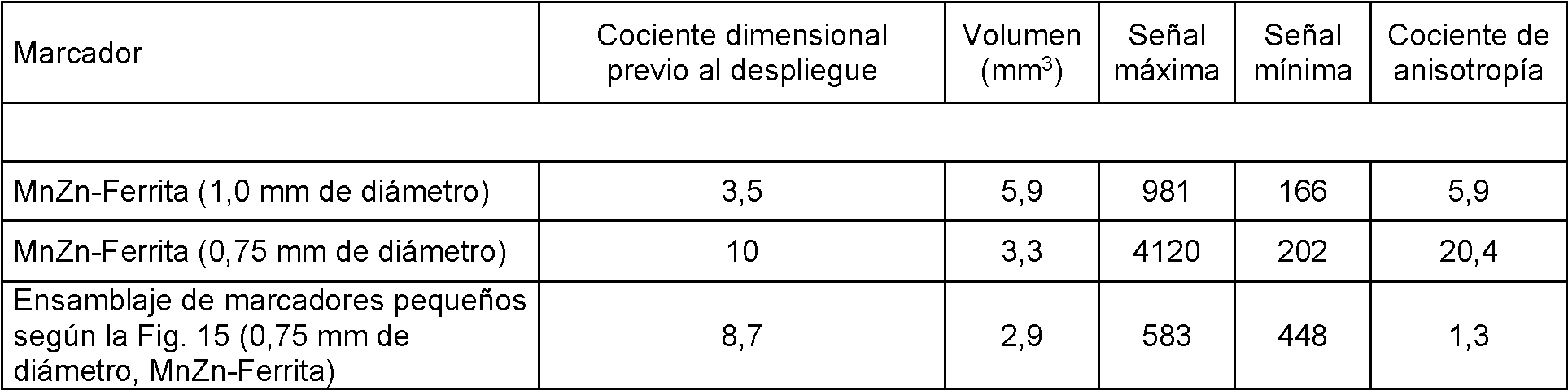
En un ejemplo adicional de esto, los marcadores o partículas magnéticamente blandos encerrados en el interior de superficies hidrófobas (nanotexturación a través del efecto loto, nanorrecubrimientos de sílice, EnBio CoBlast PTFE, hidroxiapitito, recubrimientos de nanotubos de carbono, carburo de calcio precipitado y recubrimiento de un ácido graso con látex polimérico, nanocompuestos de poliestireno de óxido de manganeso o de poliestireno de óxido de cinc) o esferas, se juntarán (autoensamblarán) durante el despliegue en el paciente. Para minimizar la energía superficial, esta realización formará una forma muy compactada tal como una esfera o un sistema elipsoidal que tendrá una anisotropía magnética de la susceptibilidad mejorada con respecto a las partículas del interior del sistema de administración, que estarán restringidas en una forma alargada que va a ser alargada. La Fig. 16 representa marcadores o partículas recubiertas hidrofóbicamente que se autoensamblan, para minimizar la energía superficial, en un marcador magnético asociado con una cantidad de material sustancialmente uniforme en todas las direcciones, minimizando la anisotropía.In a further example of this, magnetically soft markers or particles enclosed within hydrophobic surfaces (nano-texturing through the lotus effect, silica nano-coatings, EnBio CoBlast PTFE, hydroxyapitite, carbon nanotube coatings, precipitated calcium carbide and coating polymeric latex fatty acid, manganese oxide polystyrene or zinc oxide polystyrene nanocomposites) or spheres will come together (self-assemble) during deployment to the patient. To minimize surface energy, this embodiment will form a highly compacted shape such as a sphere or ellipsoidal system that will have improved susceptibility magnetic anisotropy with respect to particles within the delivery system, which will be constrained into an elongated shape that it's going to be elongated. Fig. 16 depicts hydrophobically coated markers or particles that self-assemble, to minimize surface energy, into a magnetic marker associated with a substantially uniform amount of material in all directions, minimizing anisotropy.
En otro aspecto de la invención, puede suspenderse pequeños micromarcadores o micropartículas de un material blando en el interior de una matriz biocompatible (Figs. 17(A) y (B)). El control de la distribución de las partículas magnéticas, de una forma similar a la analizada con respecto a las Figs. 10-12, permite una disminución en la anisotropía magnética de la susceptibilidad, así como la independencia de la forma exterior. También puede usarse para garantizar una ubicación establecida y una orientación entre los marcadores magnéticos.In another aspect of the invention, small micromarkers or microparticles of a soft material can be suspended within a biocompatible matrix (Figs. 17 (A) and (B)). The control of the distribution of the magnetic particles, in a similar way to that analyzed with respect to Figs. 10-12, allows a decrease in the magnetic anisotropy of the susceptibility, as well as the independence of the external shape. It can also be used to ensure a set location and orientation between magnetic markers.
En un ejemplo adicional de esto para el caso, usando una matriz de gel con una suspensión de partículas magnéticamente blandas y dimensionando estas partículas apropiadamente, el gel y las partículas pueden ser desplegados a través de la aguja de despliegue (Fig. 17(B)). La forma del gel y las partículas desplegadas estará restringida únicamente por el sitio de inyección (es decir, el tejido de una lesión) que es menor en comparación con el de la aguja. Este gel también puede establecerse con la inyección, haciendo que sea menos probable que migre de su ubicación desplegada y que sea más fácil de eliminar quirúrgicamente si se está eliminando el tejido. Si fuera necesario, podría realizarse la adición de otras partículas tales como oro para proporcionar una respuesta radiopaca adicional para la visualización con rayos X. Para la localización del marcador, la anisotropía debería ser menor o igual a 9, preferentemente menor o igual a 6, más preferentemente menor o igual a 3.In a further example of this for the case, using a gel matrix with a suspension of magnetically soft particles and sizing these particles appropriately, the gel and the particles can be deployed through the deployment needle (Fig. 17 (B) ). The shape of the gel and the unfolded particles will be restricted only by the injection site (ie tissue of a lesion) which is smaller compared to that of the needle. This gel can also settle on injection, making it less likely to migrate from its deployed location and easier to remove surgically if tissue is being removed. If necessary, the addition of other particles such as gold could be made to provide an additional radiopaque response for X-ray visualization. For marker localization, the anisotropy should be less than or equal to 9, preferably less than or equal to 6, more preferably less than or equal to 3.
La presente divulgación proporciona varias formas de fabricar marcadores magnéticos con un anisotropía aceptable sin afectar a la facilidad de administración de las partículas.The present disclosure provides various ways to manufacture magnetic markers with acceptable anisotropy without affecting the ease of delivery of the particles.
En otro aspecto de la divulgación, se proporciona un método para marcar un sitio de tejido blando de interés, tal como el sitio de un tumor o una lesión benigna, por ejemplo, dentro de la mama, el pulmón, el intestino/colon, el recto, la próstata u otro órgano afectado con cáncer, o un nódulo linfático de la axila u otro lecho linfático del cuerpo. El método incluye las etapas de (i) insertar dicho marcador magnético en un tejido próximo a la lesión o sitio objetivo, y (ii) detectar dicho marcador usando un susceptómetro, y opcionalmente (iii) extirpar quirúrgicamente el tejido objetivo alrededor del marcador. Preferentemente, el susceptómetro detecta el marcador proporcionando un campo magnético en la región del marcador y midiendo la magnetización inducida en el marcador.In another aspect of the disclosure, a method is provided for marking a soft tissue site of interest, such as the site of a tumor or benign lesion, for example, within the breast, lung, intestine / colon, the rectum, prostate or other organ affected with cancer, or a lymph node in the armpit or other lymphatic bed of the body. The method includes the steps of (i) inserting said magnetic marker into tissue near the lesion or target site, and (ii) detecting said marker using a susceptometer, and optionally (iii) surgically excising the target tissue around the marker. Preferably, the susceptometer detects the marker by providing a magnetic field in the region of the marker and measuring the magnetization induced in the marker.
Salvo que se indique lo contrario, todas las cifras que expresan longitudes, anchuras, profundidades u otras dimensiones, y similares, usados en la memoria descriptiva y en las reivindicaciones, debe entenderse en todos los casos que indican tanto los valores exactos según se muestran como que están modificadas por el término "aproximadamente". Por consiguiente, a menos que se indique lo contrario, los parámetros numéricos establecidos en la memoria descriptiva y en las reivindicaciones son aproximaciones que pueden variar dependiendo de las propiedades deseadas que se desean obtener. Finalmente, y no como un intento de limitar la aplicación de la doctrina de equivalentes al ámbito de las reivindicaciones, cada parámetro numérico debe interpretarse al menos a la luz del número de cifras significativas notificadas y aplicando las técnicas de redondeo habituales.Unless otherwise indicated, all figures expressing lengths, widths, depths or other dimensions, and the like, used in the specification and claims, should be understood in all cases to indicate both the exact values as shown and which are modified by the term "approximately". Accordingly, unless otherwise indicated, the numerical parameters set forth in the specification and in the claims are approximations that may vary depending on the desired properties that are desired to be obtained. Finally, and not as an attempt to limit the application of the doctrine of equivalents to the scope of the claims, each numerical parameter should be interpreted at least in light of the number of significant figures reported and applying the usual rounding techniques.
Debe interpretarse que los términos "un/a" "uno/a", "el/la" y los referentes similares usados en el contexto de descripción de la invención (especialmente en el contexto de las siguientes reivindicaciones) cubren tanto el singular como el plural, salvo que se indique lo contrario en el presente documento o el contexto lo contradiga claramente. Todos los métodos descritos en el presente documento pueden realizarse en cualquier orden adecuado salvo que se indique lo contrario en el presente documento o que de otro modo el contexto lo contradiga claramente. El uso de cualquiera y todos los ejemplos o lenguaje ejemplar (por ejemplo, "tal como") proporcionados en el presente documento pretende simplemente iluminar mejor la invención y no supone una limitación del ámbito de cualquier reivindicación. Debería interpretarse que ningún lenguaje de la memoria descriptiva indica cualquier elemento no reivindicado esencial para la práctica de la invención.The terms "a", "an", "the" and similar referents used in the context of describing the invention (especially in the context of the following claims) should be interpreted as covering both the singular and the plural, unless otherwise indicated in this document or the context clearly contradicts it. All of the methods described herein may be performed in any suitable order unless otherwise indicated herein or otherwise clearly contradicted by the context. Use of any and all examples or exemplary language (eg, "such as") provided herein The document is merely intended to better illuminate the invention and is not intended to limit the scope of any claim. No language in the specification should be construed to indicate any unclaimed items essential to the practice of the invention.
No debe interpretarse la agrupación de elementos o de realizaciones alternativas divulgadas en el presente documento como limitaciones. Cada miembro del grupo puede estar indicado y reivindicado individualmente o en cualquier combinación con otros miembros del grupo u otros elementos encontrados en el presente documento. Se anticipa que uno o más miembros de un grupo puede ser incluido en, o eliminado de, un grupo por razones de conveniencia y/o de patentabilidad. Cuando se produce cualquiera de dichas inclusiones o deleciones, se considera que la memoria descriptiva contiene el grupo como se ha modificado, cumpliendo por tanto la descripción escrita de todos los grupos de Markush usados en las reivindicaciones adjuntas.The grouping of elements or alternative embodiments disclosed herein should not be construed as limitations. Each group member may be indicated and claimed individually or in any combination with other group members or other elements found herein. It is anticipated that one or more members of a group may be included in, or removed from, a group for reasons of convenience and / or patentability. When any such inclusion or deletion occurs, the specification is considered to contain the group as modified, thereby meeting the written description of all Markush groups used in the appended claims.
En el presente documento se describen ciertas realizaciones, que incluyen el mejor modo conocido por el inventor para llevar a cabo el espíritu de la presente divulgación. Por supuesto, para los expertos habituales en la técnica serán evidentes variaciones de estas realizaciones descritas tras la lectura de la anterior descripción. El inventor espera que los artesanos expertos empleen dichas variaciones según sea apropiado, y el inventor pretende que la invención se lleve a la práctica de un modo distinto al descrito específicamente en el presente documento.Certain embodiments are described herein, including the best mode known to the inventor to carry out the spirit of the present disclosure. Of course, variations on these described embodiments will be apparent to those of ordinary skill in the art upon reading the foregoing description. The inventor expects skilled artisans to employ such variations as appropriate, and the inventor intends that the invention be practiced in a manner other than that specifically described herein.
En conclusión, debe entenderse que las realizaciones divulgadas en el presente documento son ilustrativas de los principios de las reivindicaciones. Otras modificaciones que pudieran emplearse están en el ámbito de las reivindicaciones. Por lo tanto, a modo de ejemplo, pero no como limitación, pueden utilizarse realizaciones alternativas de acuerdo con las enseñanzas del presente documento. Por consiguiente, las reivindicaciones no están limitadas a las realizaciones exactamente como se muestra y se describe. In conclusion, it is to be understood that the embodiments disclosed herein are illustrative of the principles of the claims. Other modifications that could be employed are within the scope of the claims. Therefore, by way of example, but not limitation, alternative embodiments may be used in accordance with the teachings herein. Accordingly, the claims are not limited to the embodiments exactly as shown and described.
Claims (13)
Applications Claiming Priority (2)
| Application Number | Priority Date | Filing Date | Title |
|---|---|---|---|
| US201562170768P | 2015-06-04 | 2015-06-04 | |
| PCT/GB2016/051649 WO2016193753A2 (en) | 2015-06-04 | 2016-06-03 | Marker materials and forms for magnetic marker localization (mml) |
Publications (1)
| Publication Number | Publication Date |
|---|---|
| ES2833377T3 true ES2833377T3 (en) | 2021-06-15 |
Family
ID=56119700
Family Applications (1)
| Application Number | Title | Priority Date | Filing Date |
|---|---|---|---|
| ES16728722T Active ES2833377T3 (en) | 2015-06-04 | 2016-06-03 | Marker Materials and Ways to Locate a Magnetic Marker |
Country Status (10)
| Country | Link |
|---|---|
| US (4) | US10595957B2 (en) |
| EP (3) | EP3782575A1 (en) |
| JP (1) | JP6821665B2 (en) |
| KR (1) | KR102589814B1 (en) |
| CN (2) | CN107920865B (en) |
| AU (1) | AU2016272550B2 (en) |
| CA (1) | CA2988065C (en) |
| ES (1) | ES2833377T3 (en) |
| MX (1) | MX390935B (en) |
| WO (1) | WO2016193753A2 (en) |
Families Citing this family (25)
| Publication number | Priority date | Publication date | Assignee | Title |
|---|---|---|---|---|
| US9936892B1 (en) | 2009-05-04 | 2018-04-10 | Cortex Manufacturing Inc. | Systems and methods for providing a fiducial marker |
| WO2014081940A1 (en) | 2012-11-21 | 2014-05-30 | Trustees Of Boston University | Tissue markers and uses thereof |
| ES2833377T3 (en) * | 2015-06-04 | 2021-06-15 | Endomagnetics Ltd | Marker Materials and Ways to Locate a Magnetic Marker |
| JP2018516129A (en) * | 2015-06-04 | 2018-06-21 | コーニンクレッカ フィリップス エヌ ヴェKoninklijke Philips N.V. | Determination of object position such as brachytherapy seed |
| CN105852984B (en) * | 2016-03-23 | 2020-02-18 | 堃博生物科技(上海)有限公司 | Lung marker |
| JP2019535339A (en) * | 2016-09-09 | 2019-12-12 | サニーブルック リサーチ インスティテュート | System and method for localization and imaging of magnetic potential lesions |
| GB2582123B (en) | 2018-01-25 | 2021-04-28 | Endomagnetics Ltd | Systems and methods for detecting magnetic markers for surgical guidance |
| GB2573500B (en) * | 2018-03-23 | 2020-11-04 | Endomagnetics Ltd | Magnetic markers for surgical guidance |
| US11266481B2 (en) | 2018-10-12 | 2022-03-08 | Hologic, Inc. | Tissue localization marker with D-shaped cross-section |
| EP3864507B1 (en) * | 2018-10-12 | 2026-03-25 | Hologic, Inc. | Tissue localization device |
| WO2020154934A1 (en) * | 2019-01-30 | 2020-08-06 | 唐山哈船科技有限公司 | Operation assistant locator |
| KR102251651B1 (en) * | 2019-03-19 | 2021-05-14 | 오스템임플란트 주식회사 | Method for generating curve line automatically for panoramic image generation and dental image processing apparatus for the same |
| CN113873963A (en) * | 2019-05-30 | 2021-12-31 | Devicor医疗产业收购公司 | Biopsy site marker for limited migration |
| GB2585034A (en) * | 2019-06-25 | 2020-12-30 | Endomagnetics Ltd | Hyperthermia implants and a method and system for heating the implant |
| JP7273428B2 (en) * | 2019-07-10 | 2023-05-15 | 京都府公立大学法人 | medical image guidance marker |
| WO2021081079A1 (en) * | 2019-10-23 | 2021-04-29 | Clemson University | A breast tissue marker and localization system |
| US11166782B1 (en) * | 2020-07-19 | 2021-11-09 | Sirius Medical Systems B.V. | Implantable marker and a method of implanting markers |
| JP2023545354A (en) * | 2020-10-07 | 2023-10-30 | カムトムサム・アクチボラグ | Alignment marker that serves as a reference for radiotherapy |
| JP7541784B2 (en) * | 2021-07-30 | 2024-08-29 | 株式会社 マトリックス細胞研究所 | Magnetic Marker Set |
| GB2612597B8 (en) | 2021-11-03 | 2025-02-12 | Endomagnetics Ltd | Improvements in or relating to implantable ferromagnetic markers |
| GB2612598B8 (en) * | 2021-11-03 | 2025-02-12 | Endomagnetics Ltd | Magnetic markers for imaging and surgical guidance |
| WO2023150781A1 (en) * | 2022-02-07 | 2023-08-10 | Anttila Eric D | Medical systems, devices, and kits useful in performing treatment under magnetic resonance imaging and related methods |
| GB2620722B (en) | 2022-04-05 | 2024-12-04 | Endomagnetics Ltd | Improvements in or relating to susceptibility probes for detecting surgical markers |
| GB2617357B (en) * | 2022-04-05 | 2024-09-11 | Endomagnetics Ltd | Improvements in or relating to susceptibility probes for detecting surgical markers |
| CN115089216A (en) * | 2022-06-20 | 2022-09-23 | 暨南大学附属第一医院(广州华侨医院) | An in vivo navigation method for an intravascular ultrasound probe |
Family Cites Families (181)
| Publication number | Priority date | Publication date | Assignee | Title |
|---|---|---|---|---|
| US2614164A (en) | 1947-11-12 | 1952-10-14 | Schlumberger Well Surv Corp | Mutual inductance system |
| US3449662A (en) | 1963-10-16 | 1969-06-10 | American Mach & Foundry | Magnetic inspection method and apparatus using resilient magnetizing means and resilient sensors |
| US3445928A (en) | 1966-03-25 | 1969-05-27 | Bunker Ramo | Magnetometer method of manufacture |
| US3492566A (en) | 1967-09-01 | 1970-01-27 | Canadian Patents Dev | Three dimensional magnetic anisotropic susceptibility meter |
| US4324255A (en) | 1980-03-07 | 1982-04-13 | Barach John P | Method and apparatus for measuring magnetic fields and electrical currents in biological and other systems |
| GB2109112A (en) | 1981-10-06 | 1983-05-25 | Pantatron Systems Limited | Eddy current test probe |
| JPH0768117B2 (en) | 1983-05-06 | 1995-07-26 | ベスター・インコーポレイテツド | Vesicle formulation for controlled drug release |
| US4823113A (en) * | 1986-02-27 | 1989-04-18 | Allied-Signal Inc. | Glassy alloy identification marker |
| US5055288A (en) | 1987-06-26 | 1991-10-08 | Advanced Magnetics, Inc. | Vascular magnetic imaging method and agent comprising biodegradeable superparamagnetic metal oxides |
| US5261403A (en) | 1987-03-30 | 1993-11-16 | Hitachi, Ltd. | Magnetic resonance imaging apparatus |
| US5414356A (en) | 1987-09-21 | 1995-05-09 | Hitachi, Ltd. | Fluxmeter including squid and pickup coil with flux guiding core and method for sensing degree of deterioration of an object |
| US4825162A (en) | 1987-12-07 | 1989-04-25 | General Electric Company | Nuclear magnetic resonance (NMR) imaging with multiple surface coils |
| JP2613275B2 (en) | 1988-09-16 | 1997-05-21 | 株式会社日立製作所 | Fluxmeter using superconducting quantum interference device |
| EP0390935A1 (en) | 1989-03-29 | 1990-10-10 | Siemens Aktiengesellschaft | Calibration method for multichannel squid systems with gradiometers in any order |
| US5442289A (en) | 1989-07-31 | 1995-08-15 | Biomagnetic Technologies, Inc. | Biomagnetometer having flexible sensor |
| DE4003330A1 (en) | 1990-02-05 | 1991-08-08 | Foerster Inst Dr Friedrich | Eddy current tester |
| US5005001A (en) | 1990-04-05 | 1991-04-02 | Pitney Bowes Inc. | Field generation and reception system for electronic article surveillance |
| US5512821A (en) | 1991-06-04 | 1996-04-30 | Nkk Corporation | Method and apparatus for magnetically detecting defects in an object with compensation for magnetic field shift by means of a compensating coil |
| US5293119A (en) | 1992-02-20 | 1994-03-08 | Sqm Technology, Inc. | Electromagnetic microscope for evaluation of electrically conductive and magnetic materials |
| JP2882167B2 (en) | 1992-03-06 | 1999-04-12 | ダイキン工業株式会社 | SQUID magnetometer |
| FR2689638B1 (en) | 1992-04-06 | 1996-08-09 | Aerospatiale | EDDY CURRENT SENSOR. |
| US5313192A (en) * | 1992-07-02 | 1994-05-17 | Sensormatic Electronics Corp. | Deactivatable/reactivatable magnetic marker having a step change in magnetic flux |
| ES2130406T5 (en) | 1992-08-05 | 2003-12-16 | Meito Sangyo Kk | COMPOSITE MATERIAL OF SMALL DIAMETER COMPOSITE OF CARBOXIPOLISACARIDO SOLUBLE IN WATER AND MAGNETIC IRON OXIDE. |
| DE4226814A1 (en) | 1992-08-13 | 1994-02-17 | Philips Patentverwaltung | Coil arrangement for MR examinations of the breast |
| US6023165A (en) | 1992-09-28 | 2000-02-08 | Fonar Corporation | Nuclear magnetic resonance apparatus and methods of use and facilities for incorporating the same |
| US5575794A (en) | 1993-02-12 | 1996-11-19 | Walus; Richard L. | Tool for implanting a fiducial marker |
| US5537037A (en) | 1993-03-16 | 1996-07-16 | Hitachi, Ltd. | Apparatus with cancel coil assembly for cancelling a field parallel to an axial direction to the plural coils and to a squid pick up coil |
| JPH06324021A (en) | 1993-03-16 | 1994-11-25 | Hitachi Ltd | Non-destructive inspection device |
| EP0997109B1 (en) | 1993-04-26 | 2003-06-18 | ST. Louis University | Indicating the position of a surgical probe |
| US5590654A (en) | 1993-06-07 | 1997-01-07 | Prince; Martin R. | Method and apparatus for magnetic resonance imaging of arteries using a magnetic resonance contrast agent |
| US5363845A (en) | 1993-08-13 | 1994-11-15 | Medical Advances, Inc. | Breast coil for magnetic resonance imaging |
| BE1007459A3 (en) | 1993-08-24 | 1995-07-04 | Philips Electronics Nv | A magnetic resonance apparatus. |
| US5437280A (en) | 1993-09-20 | 1995-08-01 | Hussman; Karl L. | Magnetic resonance breast localizer |
| JPH0815229A (en) | 1994-06-27 | 1996-01-19 | Mitsubishi Heavy Ind Ltd | High resolution eddy current flaw detector |
| US5402094A (en) | 1994-08-15 | 1995-03-28 | Enge; Harald A. | MRI mammography magnet |
| JPH10508504A (en) | 1994-09-16 | 1998-08-25 | バイオプシス メディカル インコーポレイテッド | Method and apparatus for identifying and marking tissue |
| DE19503664C2 (en) * | 1995-01-27 | 1998-04-02 | Schering Ag | Magnetorelaxometric detection of analytes |
| JP3910222B2 (en) | 1995-03-10 | 2007-04-25 | 株式会社豊田中央研究所 | Fatigue measuring device |
| US5657756A (en) | 1995-06-07 | 1997-08-19 | Ctf Systems Inc. | Method and systems for obtaining higher order gradiometer measurements with lower order gradiometers |
| JP3580905B2 (en) | 1995-06-13 | 2004-10-27 | 大日本印刷株式会社 | Magnetic sensor |
| JP3499054B2 (en) | 1995-07-11 | 2004-02-23 | 独立行政法人 国立印刷局 | Authenticity determination device for safety paper |
| US5842986A (en) | 1995-08-16 | 1998-12-01 | Proton Sciences Corp. | Ferromagnetic foreign body screening method and apparatus |
| DE19532676C1 (en) | 1995-09-05 | 1997-05-07 | Inst Physikalische Hochtech Ev | Arrangement for determining the position of a marker in a cavity within the organism of a living being |
| DK0876140T3 (en) | 1996-01-25 | 2003-12-15 | Schering Ag | Improved contrast agent solutions for intravasal use |
| JP2000509014A (en) | 1996-03-11 | 2000-07-18 | フォーカル,インコーポレイテッド | Polymer delivery of radionuclides and radiopharmaceuticals |
| JPH1038854A (en) | 1996-07-17 | 1998-02-13 | Agency Of Ind Science & Technol | Non-destructive inspection method and apparatus for conductive material |
| EP1284123B1 (en) | 1996-08-12 | 2005-07-20 | Ethicon Endo-Surgery, Inc. | Apparatus for marking tissue |
| AU4070697A (en) | 1996-08-16 | 1998-03-06 | Jon Neal Weaver | Anti-shoplifting security system |
| US5844140A (en) | 1996-08-27 | 1998-12-01 | Seale; Joseph B. | Ultrasound beam alignment servo |
| US5997473A (en) | 1996-09-06 | 1999-12-07 | Olympus Optical Co., Ltd. | Method of locating a coil which consists of determining the space occupied by a source coil generating a magnetic field |
| DE29724862U1 (en) | 1996-09-18 | 2004-12-30 | Ifm Electronic Gmbh | Inductive proximity switch for electrical and electronic switching, measurement and control circuit - has two transmission coils arranged one after other in direction of influence, with receiver coils connected to evaluation circuit and mounted centrally between transmitter coils |
| WO1998029712A1 (en) | 1996-12-27 | 1998-07-09 | Bic-Neisse Gmbh | Magnetic resonance sensor |
| US6406420B1 (en) | 1997-01-02 | 2002-06-18 | Myocor, Inc. | Methods and devices for improving cardiac function in hearts |
| AU2869900A (en) | 1997-02-27 | 2000-08-25 | Uri Rapoport | Method and apparatus for detecting a magnetically responsive substance |
| GB9712524D0 (en) | 1997-06-16 | 1997-08-20 | Nycomed Imaging As | Method |
| FR2770779B1 (en) | 1997-11-10 | 2000-07-21 | Bernstein Veronique | HYPOTONIC OR HYPOOSMOLAR PLASMA SOLUTE FOR THE TREATMENT OF CELLULITE, FIBROSIS, AND HIRSUTISM |
| US6270464B1 (en) | 1998-06-22 | 2001-08-07 | Artemis Medical, Inc. | Biopsy localization method and device |
| US6205352B1 (en) | 1997-11-19 | 2001-03-20 | Oncology Innovations, Inc. | Sentinel node identification using non-isotope means |
| CA2260703A1 (en) | 1998-04-07 | 1999-10-07 | Dennis W. Szymaitis | Disposal container for detecting, distinguishing and counting objects |
| US6347241B2 (en) | 1999-02-02 | 2002-02-12 | Senorx, Inc. | Ultrasonic and x-ray detectable biopsy site marker and apparatus for applying it |
| US6161034A (en) | 1999-02-02 | 2000-12-12 | Senorx, Inc. | Methods and chemical preparations for time-limited marking of biopsy sites |
| AU2001217746A1 (en) | 1998-05-14 | 2002-05-27 | Calypso Medical, Inc. | Systems and methods for locating and defining a target location within a human body |
| US5941890A (en) | 1998-06-26 | 1999-08-24 | Ethicon Endo-Surgery, Inc. | Implantable surgical marker |
| CN1167087C (en) * | 1998-11-26 | 2004-09-15 | 住友特殊金属株式会社 | Ferrite magnet powder, magnet using same, and their manufacturing method |
| US6371904B1 (en) | 1998-12-24 | 2002-04-16 | Vivant Medical, Inc. | Subcutaneous cavity marking device and method |
| US6356782B1 (en) | 1998-12-24 | 2002-03-12 | Vivant Medical, Inc. | Subcutaneous cavity marking device and method |
| US6230038B1 (en) | 1999-02-01 | 2001-05-08 | International Business Machines Corporation | Imaging of internal structures of living bodies by sensing implanted magnetic devices |
| US6725083B1 (en) | 1999-02-02 | 2004-04-20 | Senorx, Inc. | Tissue site markers for in VIVO imaging |
| US7983734B2 (en) | 2003-05-23 | 2011-07-19 | Senorx, Inc. | Fibrous marker and intracorporeal delivery thereof |
| US6862470B2 (en) | 1999-02-02 | 2005-03-01 | Senorx, Inc. | Cavity-filling biopsy site markers |
| US6173715B1 (en) | 1999-03-01 | 2001-01-16 | Lucent Medical Systems, Inc. | Magnetic anatomical marker and method of use |
| GB9908179D0 (en) * | 1999-04-09 | 1999-06-02 | Univ Cambridge Tech | Magnetic materials |
| EP1171032A4 (en) | 1999-04-15 | 2008-10-29 | Surgi Vision | METHODS FOR IN VIVO MAGNETIC RESONANCE IMAGING |
| EP1178837A2 (en) | 1999-04-21 | 2002-02-13 | THE GOVERNMENT OF THE UNITED STATES OF AMERICA, as represented by THE SECRETARY, DEPARTMENT OF HEALTH AND HUMAN SERVICES | Method for enhancing contrast produced by mri |
| US6292678B1 (en) * | 1999-05-13 | 2001-09-18 | Stereotaxis, Inc. | Method of magnetically navigating medical devices with magnetic fields and gradients, and medical devices adapted therefor |
| US6766186B1 (en) | 1999-06-16 | 2004-07-20 | C. R. Bard, Inc. | Post biospy tissue marker and method of use |
| JP2001000430A (en) | 1999-06-24 | 2001-01-09 | Alcare Co Ltd | Marker for imaging |
| WO2001008578A1 (en) * | 1999-07-30 | 2001-02-08 | Vivant Medical, Inc. | Device and method for safe location and marking of a cavity and sentinel lymph nodes |
| US6835572B1 (en) | 1999-10-18 | 2004-12-28 | Institute For Magnetic Resonance Research | Magnetic resonance spectroscopy of breast biopsy to determine pathology, vascularization and nodal involvement |
| JP2001255358A (en) | 2000-03-10 | 2001-09-21 | Sumitomo Electric Ind Ltd | Magnetic sensor |
| US7283868B2 (en) | 2000-04-07 | 2007-10-16 | The Johns Hopkins University | Apparatus for sensing human prostate tumor |
| US6889073B2 (en) | 2000-05-08 | 2005-05-03 | David A. Lampman | Breast biopsy and therapy system for magnetic resonance imagers |
| JP2002004118A (en) * | 2000-06-21 | 2002-01-09 | Unitika Ltd | Garment for poriomania patient |
| AU2001273133A1 (en) | 2000-08-10 | 2002-02-25 | Cook Incorporated | Localizer needle |
| US6394965B1 (en) | 2000-08-15 | 2002-05-28 | Carbon Medical Technologies, Inc. | Tissue marking using biocompatible microparticles |
| AU2003267309A1 (en) | 2000-11-16 | 2004-04-08 | Microspherix Llc | Flexible and/or elastic brachytherapy seed or strand |
| CA2446993C (en) | 2000-11-20 | 2009-06-02 | Senorx, Inc. | Tissue site markers for in vivo imaging |
| FR2823092B1 (en) | 2001-04-10 | 2004-03-05 | Eurorad 2 6 | PER-OPERATIVE DEVICE FOR LOCATING MARKED TISSUES AND METHOD USING SUCH A DEVICE |
| EP1383416A2 (en) * | 2001-04-18 | 2004-01-28 | BBMS Ltd. | Navigating and maneuvering of an in vivo vechicle by extracorporeal devices |
| JP4193382B2 (en) | 2001-07-19 | 2008-12-10 | 株式会社日立製作所 | Magnetic field measuring device |
| US6850065B1 (en) | 2001-07-27 | 2005-02-01 | General Electric Company | MRI coil system for breast imaging |
| US6592608B2 (en) | 2001-12-07 | 2003-07-15 | Biopsy Sciences, Llc | Bioabsorbable sealant |
| ITSV20010029A1 (en) | 2001-08-14 | 2003-02-14 | Esaote Spa | NUCLEAR MAGNETIC RESONANCE IMAGE DETECTION MRI (MRI) |
| US20030141868A1 (en) | 2001-08-23 | 2003-07-31 | Bakharev Alexander A. | High balance gradiometer |
| US7135978B2 (en) | 2001-09-14 | 2006-11-14 | Calypso Medical Technologies, Inc. | Miniature resonating marker assembly |
| US7701209B1 (en) | 2001-10-05 | 2010-04-20 | Fonar Corporation | Coils for horizontal field magnetic resonance imaging |
| US20090281416A1 (en) * | 2004-12-22 | 2009-11-12 | Koninklijke Philips Electronics, N.V. | Arrangement and method for determining the spatial distribution of magnetic particles |
| JP4090722B2 (en) | 2001-10-23 | 2008-05-28 | 純一 小川 | Magnetic fluid detection device |
| US20030216632A1 (en) | 2001-10-29 | 2003-11-20 | Mednovus, Inc. | Ferromagnetic sensing method and apparatus |
| JP2003149212A (en) | 2001-11-09 | 2003-05-21 | Japan Science & Technology Corp | Non-destructive inspection equipment |
| EP1460970A4 (en) | 2001-12-03 | 2010-03-17 | Carl E Fabian | Portable surgical implement detector |
| WO2003051217A2 (en) | 2001-12-14 | 2003-06-26 | Monteris Medical Inc. | Hyperthermia treatment and probe therefor |
| JP2003315373A (en) | 2002-04-18 | 2003-11-06 | Toshiba Corp | Current detection device and semiconductor device |
| US7329414B2 (en) | 2002-05-03 | 2008-02-12 | Biopsy Sciences, Llc | Biodegradable polymer for marking tissue and sealing tracts |
| JP4221192B2 (en) | 2002-06-14 | 2009-02-12 | 株式会社日立ハイテクノロジーズ | Biomagnetic measurement device |
| US20040162477A1 (en) | 2002-10-04 | 2004-08-19 | Olympus Corporation | Apparatus for detecting magnetic fluid identifying sentinel-lymph node |
| US20060173283A1 (en) | 2002-11-27 | 2006-08-03 | Oskar Axelsson | Method of magnetic resonance imaging |
| ATE428112T1 (en) | 2002-12-13 | 2009-04-15 | Mauro Marinelli | SUSCEPTIBILITY MEASUREMENT DEVICE FOR THE NON-INVASIVE MEASUREMENT OF THE IRON CONTENT IN A BODY |
| US7009398B2 (en) | 2003-03-20 | 2006-03-07 | Siemens Aktiengesellschaft | Portable magnetic resonance surface coil unit with an access opening for manual gripping |
| US20070010702A1 (en) * | 2003-04-08 | 2007-01-11 | Xingwu Wang | Medical device with low magnetic susceptibility |
| US7877133B2 (en) | 2003-05-23 | 2011-01-25 | Senorx, Inc. | Marker or filler forming fluid |
| US7783336B2 (en) | 2003-06-06 | 2010-08-24 | Ethicon Endo-Surgery, Inc. | Subcutaneous biopsy cavity marker device |
| US7744852B2 (en) | 2003-07-25 | 2010-06-29 | Rubicor Medical, Llc | Methods and systems for marking post biopsy cavity sites |
| US20050033157A1 (en) | 2003-07-25 | 2005-02-10 | Klein Dean A. | Multi-modality marking material and method |
| US7001341B2 (en) | 2003-08-13 | 2006-02-21 | Scimed Life Systems, Inc. | Marking biopsy sites |
| US7084631B2 (en) | 2003-11-19 | 2006-08-01 | General Electric Company | Magnetic resonance imaging array coil system and method for breast imaging |
| US20050148863A1 (en) | 2003-12-09 | 2005-07-07 | Toshiro Okamura | Magnetic fluid detection device |
| JP4217599B2 (en) | 2003-12-09 | 2009-02-04 | オリンパス株式会社 | Magnetic fluid detection device |
| US8118754B1 (en) | 2007-11-15 | 2012-02-21 | Flynn Edward R | Magnetic needle biopsy |
| US20050234336A1 (en) * | 2004-03-26 | 2005-10-20 | Beckman Andrew T | Apparatus and method for marking tissue |
| US7386338B2 (en) | 2004-04-30 | 2008-06-10 | General Electric Company | Bilateral imaging apparatus |
| US7708751B2 (en) | 2004-05-21 | 2010-05-04 | Ethicon Endo-Surgery, Inc. | MRI biopsy device |
| JP3896489B2 (en) | 2004-07-16 | 2007-03-22 | 国立大学法人 岡山大学 | Magnetic detection device and substance determination device |
| US7116094B2 (en) | 2004-07-28 | 2006-10-03 | International Business Machines Corporation | Apparatus and method for transmission and remote sensing of signals from integrated circuit devices |
| WO2006022786A1 (en) | 2004-08-20 | 2006-03-02 | David Mullen | Tissue marking devices and systems |
| US20060074295A1 (en) | 2004-10-01 | 2006-04-06 | Nexgen | Combined MR coil technology in medical devices |
| US8060183B2 (en) | 2004-10-13 | 2011-11-15 | Suros Surgical Systems, Inc. | Site marker visible under multiple modalities |
| US8280486B2 (en) | 2004-10-13 | 2012-10-02 | Suros Surgical Systems, Inc. | Site marker visable under multiple modalities |
| US20060079805A1 (en) * | 2004-10-13 | 2006-04-13 | Miller Michael E | Site marker visable under multiple modalities |
| WO2006055829A1 (en) | 2004-11-18 | 2006-05-26 | Nedim Turan Sahin | Mri as a therapeutic device |
| WO2006056739A2 (en) | 2004-11-23 | 2006-06-01 | Quantum Medical Technology Limited | Surgical tag, magnetometer, and associated system |
| US9073060B2 (en) * | 2004-12-22 | 2015-07-07 | Giamag Technologies As | Method for forming a high-gradient magnetic field and a substance separation device based thereon |
| CN101087558B (en) * | 2004-12-22 | 2010-10-06 | 皇家飞利浦电子股份有限公司 | Markers for position determination by magnetic separation |
| DE102005002944A1 (en) * | 2005-01-18 | 2006-07-27 | Charité - Universitätsmedizin Berlin (Charité) | Endoscopic marking agent as well as instruments for application and detection of the marking agent as well as for operative fixation of the marked tissue area |
| US8467849B2 (en) | 2005-02-03 | 2013-06-18 | ORGAMEND Inc. | Magnetic resonance imaging device |
| US7842178B2 (en) * | 2005-04-18 | 2010-11-30 | University Of Iowa Research Foundation | Magnet incorporated electrically conductive electrodes |
| GB2425610A (en) | 2005-04-29 | 2006-11-01 | Univ London | Magnetic properties sensing system |
| US7831293B2 (en) | 2005-05-10 | 2010-11-09 | Advanced Clinical Solutions, Inc. | Method of defining a biological target for treatment |
| US20060293581A1 (en) | 2005-05-12 | 2006-12-28 | Sunnybrook And Women's College Health Sciences Centre | Marker device for X-ray, ultrasound and MR imaging |
| US7570056B2 (en) | 2005-08-10 | 2009-08-04 | Kabushiki Kaisha Toshiba | Magnetic resonance imaging apparatus |
| GB0519391D0 (en) | 2005-09-22 | 2005-11-02 | Aion Diagnostics Ltd | Imaging agents |
| JP5063603B2 (en) * | 2005-09-30 | 2012-10-31 | クック メディカル テクノロジーズ エルエルシー | Coated vascular occlusion device |
| US7479784B2 (en) | 2005-10-12 | 2009-01-20 | New York University | Arrangements, systems and methods for facilitating and collecting information associated with fluxes of magnetic fields provided at various angles from one another |
| UA97234C2 (en) | 2005-11-01 | 2012-01-25 | Уайєт | Sodium chloride solution for reconstituting lyophilized factor ix formulation |
| US8193804B2 (en) | 2005-11-16 | 2012-06-05 | Rex Chin-Yih Hong | Device for measuring AC magnetization of materials |
| US7702378B2 (en) | 2005-11-17 | 2010-04-20 | Breast-Med, Inc. | Tissue marker for multimodality radiographic imaging |
| US8078260B2 (en) | 2006-05-02 | 2011-12-13 | ORGAMEND Inc. | Method for improving magnetic resonance imaging of the breast |
| US8064987B2 (en) | 2006-10-23 | 2011-11-22 | C. R. Bard, Inc. | Breast marker |
| US20090024022A1 (en) | 2006-10-25 | 2009-01-22 | Siemens Corporate Research, Inc. | System and method for lymph node imaging using co-registration of ct and mr imagery |
| US20080124281A1 (en) * | 2006-11-29 | 2008-05-29 | Board Of Regents, The University Of Texas System | Nanotubular probes as ultrasensitive mr contrast agent |
| US20080146914A1 (en) | 2006-12-19 | 2008-06-19 | General Electric Company | System, method and apparatus for cancer imaging |
| DE102007009016A1 (en) | 2007-02-23 | 2008-08-28 | Siemens Ag | Marker for determining position of target tissue of human brain during e.g. surgery, has capsule which is biologically degradable after medical intrusion, and containing substance detected by detection system |
| US20080228164A1 (en) | 2007-03-14 | 2008-09-18 | Nicoson Zachary R | Implant delivery system |
| US20080255425A1 (en) | 2007-04-13 | 2008-10-16 | Ethicon Endo-Surgery, Inc. | Nanoparticle treated medical devices |
| US20080294036A1 (en) | 2007-04-23 | 2008-11-27 | Device Evolutions, Llc | Surgical Metal Detection Apparatus and Methods |
| US8137320B2 (en) | 2007-05-01 | 2012-03-20 | Suros Surgical Systems, Inc. | Securement for a surgical site marker and deployment device for same |
| US9763597B2 (en) | 2007-05-03 | 2017-09-19 | Wisconsin Alumni Research Foundation | Local MRI breast coil and method of use |
| US20090082662A1 (en) | 2007-09-24 | 2009-03-26 | Israel Henry M | Mri breast image magnet structure |
| DE102007046186A1 (en) | 2007-09-26 | 2009-04-02 | Amedo Smart Tracking Solutions Gmbh | tissue marking |
| US8731635B2 (en) | 2007-11-07 | 2014-05-20 | University of Pittsburgh—of the Commonwealth System of Higher Education | Coils for magnetic resonance spectroscopy and imaging of human breast |
| US8405477B2 (en) * | 2008-02-22 | 2013-03-26 | University Of Exeter | Controllable magnetic systems |
| DE102008015781B4 (en) * | 2008-03-26 | 2011-09-29 | Malte Neuss | Device for sealing defects in the vascular system |
| US8050742B2 (en) | 2008-07-30 | 2011-11-01 | Devicor Medical Products, Inc. | Biopsy device |
| DE102008048291B4 (en) | 2008-09-22 | 2012-02-16 | Siemens Aktiengesellschaft | Breast coil assembly for magnetic resonance applications |
| GB2465771A (en) | 2008-11-28 | 2010-06-02 | Helyn Margaret Wright | Surgical Localisation Device |
| EP2756799B1 (en) | 2009-06-26 | 2016-04-20 | Cianna Medical, Inc. | System for localizing markers or tissue structures within a body |
| GB0916334D0 (en) | 2009-09-17 | 2009-10-28 | Renovo Ltd | Inhibition of tendon adhesions |
| US10634741B2 (en) | 2009-12-04 | 2020-04-28 | Endomagnetics Ltd. | Magnetic probe apparatus |
| US9427186B2 (en) | 2009-12-04 | 2016-08-30 | Endomagnetics Ltd. | Magnetic probe apparatus |
| JP5678565B2 (en) | 2009-12-08 | 2015-03-04 | Jnc株式会社 | Magnetic fine particles and method for producing the same |
| US8870898B2 (en) | 2010-01-05 | 2014-10-28 | GI Windows, Inc. | Self-assembling magnetic anastomosis device having an exoskeleton |
| JP2012177691A (en) * | 2011-02-04 | 2012-09-13 | Hitachi Maxell Ltd | Magnetic marker particle |
| DE102011081445A1 (en) * | 2011-08-23 | 2013-02-28 | Epflex Feinwerktechnik Gmbh | Medical guide wire for e.g. MRI application, has wire core whose wire threads are formed by non-metallic fiber that is volume-doped with magnetic resonance-marker, where magnetic resonance-marker is provided between fibers in interstices |
| JP5924641B2 (en) * | 2011-10-17 | 2016-05-25 | 学校法人東京電機大学 | Medical tube tip position detection system and medical tube applied to the system |
| US8798716B1 (en) | 2011-11-03 | 2014-08-05 | Solstice Corporation | Fiducial markers and related methods |
| WO2013114247A2 (en) | 2012-02-01 | 2013-08-08 | Koninklijke Philips N.V. | Multimodal fiducial marker and marker arrangement |
| US20140018663A1 (en) | 2012-07-16 | 2014-01-16 | Endomagnetics Ltd. | Magnetic Marker for Surgical Localization |
| CN105283202B (en) | 2013-03-11 | 2019-04-23 | 安都磁学有限公司 | Hypotonic solution for lymph node detection |
| US9234877B2 (en) * | 2013-03-13 | 2016-01-12 | Endomagnetics Ltd. | Magnetic detector |
| JP6305869B2 (en) * | 2014-08-19 | 2018-04-04 | 日立建機株式会社 | Engine control device for construction machinery |
| ES2833377T3 (en) * | 2015-06-04 | 2021-06-15 | Endomagnetics Ltd | Marker Materials and Ways to Locate a Magnetic Marker |
-
2016
- 2016-06-03 ES ES16728722T patent/ES2833377T3/en active Active
- 2016-06-03 MX MX2017015588A patent/MX390935B/en unknown
- 2016-06-03 EP EP20180295.6A patent/EP3782575A1/en active Pending
- 2016-06-03 KR KR1020187000167A patent/KR102589814B1/en active Active
- 2016-06-03 CN CN201680039792.0A patent/CN107920865B/en active Active
- 2016-06-03 CN CN202110644795.XA patent/CN113558782B/en active Active
- 2016-06-03 CA CA2988065A patent/CA2988065C/en active Active
- 2016-06-03 AU AU2016272550A patent/AU2016272550B2/en active Active
- 2016-06-03 EP EP16728722.6A patent/EP3302338B1/en active Active
- 2016-06-03 JP JP2018515358A patent/JP6821665B2/en active Active
- 2016-06-03 WO PCT/GB2016/051649 patent/WO2016193753A2/en not_active Ceased
- 2016-06-03 EP EP22176363.4A patent/EP4085866A3/en active Pending
- 2016-06-03 US US15/172,187 patent/US10595957B2/en active Active
-
2019
- 2019-11-19 US US16/688,318 patent/US11504207B2/en active Active
-
2022
- 2022-11-16 US US17/988,146 patent/US12161513B2/en active Active
-
2024
- 2024-11-14 US US18/948,054 patent/US20250064548A1/en active Pending
Also Published As
| Publication number | Publication date |
|---|---|
| CN113558782B (en) | 2024-12-10 |
| EP3302338A2 (en) | 2018-04-11 |
| US10595957B2 (en) | 2020-03-24 |
| EP3782575A1 (en) | 2021-02-24 |
| EP3302338B1 (en) | 2020-09-30 |
| EP4085866A3 (en) | 2023-01-18 |
| US12161513B2 (en) | 2024-12-10 |
| US11504207B2 (en) | 2022-11-22 |
| AU2016272550B2 (en) | 2021-01-28 |
| CN107920865A (en) | 2018-04-17 |
| KR20180015234A (en) | 2018-02-12 |
| EP4085866A2 (en) | 2022-11-09 |
| CN107920865B (en) | 2021-07-09 |
| JP2018526160A (en) | 2018-09-13 |
| CA2988065A1 (en) | 2016-12-08 |
| US20230320811A1 (en) | 2023-10-12 |
| CA2988065C (en) | 2024-03-26 |
| US20250064548A1 (en) | 2025-02-27 |
| MX2017015588A (en) | 2018-04-13 |
| WO2016193753A3 (en) | 2017-01-12 |
| AU2016272550A1 (en) | 2018-01-18 |
| CN113558782A (en) | 2021-10-29 |
| US20160354178A1 (en) | 2016-12-08 |
| MX390935B (en) | 2025-03-21 |
| JP6821665B2 (en) | 2021-01-27 |
| KR102589814B1 (en) | 2023-10-13 |
| WO2016193753A2 (en) | 2016-12-08 |
| US20200121415A1 (en) | 2020-04-23 |
Similar Documents
| Publication | Publication Date | Title |
|---|---|---|
| ES2833377T3 (en) | Marker Materials and Ways to Locate a Magnetic Marker | |
| RU2754312C9 (en) | Systems and methods for detecting magnetic markers for monitoring during surgical intervention | |
| JP5010914B2 (en) | Method for determining spatial distribution of magnetic particles and composition for administering magnetic particles | |
| ES2988293T3 (en) | Improvements in or related to implantable ferromagnetic markers | |
| JP2008543512A (en) | Rod | |
| JP2025129273A (en) | Magnetic markers for imaging and surgical guides | |
| ES3041814T3 (en) | Improvements in or relating to implantable ferromagnetic markers |