ES2836149T3 - Lens with an extended focal length range - Google Patents
Lens with an extended focal length range Download PDFInfo
- Publication number
- ES2836149T3 ES2836149T3 ES12772226T ES12772226T ES2836149T3 ES 2836149 T3 ES2836149 T3 ES 2836149T3 ES 12772226 T ES12772226 T ES 12772226T ES 12772226 T ES12772226 T ES 12772226T ES 2836149 T3 ES2836149 T3 ES 2836149T3
- Authority
- ES
- Spain
- Prior art keywords
- phi
- spiral
- lens
- refractive power
- distribution
- Prior art date
- Legal status (The legal status is an assumption and is not a legal conclusion. Google has not performed a legal analysis and makes no representation as to the accuracy of the status listed.)
- Active
Links
Classifications
-
- G—PHYSICS
- G02—OPTICS
- G02B—OPTICAL ELEMENTS, SYSTEMS OR APPARATUS
- G02B27/00—Optical systems or apparatus not provided for by any of the groups G02B1/00 - G02B26/00, G02B30/00
- G02B27/0075—Optical systems or apparatus not provided for by any of the groups G02B1/00 - G02B26/00, G02B30/00 with means for altering, e.g. increasing, the depth of field or depth of focus
-
- G—PHYSICS
- G02—OPTICS
- G02B—OPTICAL ELEMENTS, SYSTEMS OR APPARATUS
- G02B5/00—Optical elements other than lenses
- G02B5/18—Diffraction gratings
- G02B5/1842—Gratings for image generation
-
- A—HUMAN NECESSITIES
- A61—MEDICAL OR VETERINARY SCIENCE; HYGIENE
- A61F—FILTERS IMPLANTABLE INTO BLOOD VESSELS; PROSTHESES; DEVICES PROVIDING PATENCY TO, OR PREVENTING COLLAPSING OF, TUBULAR STRUCTURES OF THE BODY, e.g. STENTS; ORTHOPAEDIC, NURSING OR CONTRACEPTIVE DEVICES; FOMENTATION; TREATMENT OR PROTECTION OF EYES OR EARS; BANDAGES, DRESSINGS OR ABSORBENT PADS; FIRST-AID KITS
- A61F2/00—Filters implantable into blood vessels; Prostheses, i.e. artificial substitutes or replacements for parts of the body; Appliances for connecting them with the body; Devices providing patency to, or preventing collapsing of, tubular structures of the body, e.g. stents
- A61F2/02—Prostheses implantable into the body
- A61F2/14—Eye parts, e.g. lenses or corneal implants; Artificial eyes
- A61F2/16—Intraocular lenses
- A61F2/1613—Intraocular lenses having special lens configurations, e.g. multipart lenses; having particular optical properties, e.g. pseudo-accommodative lenses, lenses having aberration corrections, diffractive lenses, lenses for variably absorbing electromagnetic radiation, lenses having variable focus
- A61F2/1616—Pseudo-accommodative, e.g. multifocal or enabling monovision
- A61F2/1618—Multifocal lenses
-
- A—HUMAN NECESSITIES
- A61—MEDICAL OR VETERINARY SCIENCE; HYGIENE
- A61F—FILTERS IMPLANTABLE INTO BLOOD VESSELS; PROSTHESES; DEVICES PROVIDING PATENCY TO, OR PREVENTING COLLAPSING OF, TUBULAR STRUCTURES OF THE BODY, e.g. STENTS; ORTHOPAEDIC, NURSING OR CONTRACEPTIVE DEVICES; FOMENTATION; TREATMENT OR PROTECTION OF EYES OR EARS; BANDAGES, DRESSINGS OR ABSORBENT PADS; FIRST-AID KITS
- A61F2/00—Filters implantable into blood vessels; Prostheses, i.e. artificial substitutes or replacements for parts of the body; Appliances for connecting them with the body; Devices providing patency to, or preventing collapsing of, tubular structures of the body, e.g. stents
- A61F2/02—Prostheses implantable into the body
- A61F2/14—Eye parts, e.g. lenses or corneal implants; Artificial eyes
- A61F2/16—Intraocular lenses
- A61F2/1613—Intraocular lenses having special lens configurations, e.g. multipart lenses; having particular optical properties, e.g. pseudo-accommodative lenses, lenses having aberration corrections, diffractive lenses, lenses for variably absorbing electromagnetic radiation, lenses having variable focus
- A61F2/1654—Diffractive lenses
-
- G—PHYSICS
- G02—OPTICS
- G02B—OPTICAL ELEMENTS, SYSTEMS OR APPARATUS
- G02B3/00—Simple or compound lenses
-
- G—PHYSICS
- G02—OPTICS
- G02B—OPTICAL ELEMENTS, SYSTEMS OR APPARATUS
- G02B5/00—Optical elements other than lenses
- G02B5/18—Diffraction gratings
- G02B5/1814—Diffraction gratings structurally combined with one or more further optical elements, e.g. lenses, mirrors, prisms or other diffraction gratings
- G02B5/1819—Plural gratings positioned on the same surface, e.g. array of gratings
- G02B5/1823—Plural gratings positioned on the same surface, e.g. array of gratings in an overlapping or superposed manner
-
- G—PHYSICS
- G02—OPTICS
- G02B—OPTICAL ELEMENTS, SYSTEMS OR APPARATUS
- G02B5/00—Optical elements other than lenses
- G02B5/18—Diffraction gratings
- G02B5/1866—Transmission gratings characterised by their structure, e.g. step profile, contours of substrate or grooves, pitch variations, materials
- G02B5/1871—Transmissive phase gratings
-
- G—PHYSICS
- G02—OPTICS
- G02B—OPTICAL ELEMENTS, SYSTEMS OR APPARATUS
- G02B5/00—Optical elements other than lenses
- G02B5/30—Polarising elements
-
- G—PHYSICS
- G02—OPTICS
- G02C—SPECTACLES; SUNGLASSES OR GOGGLES INSOFAR AS THEY HAVE THE SAME FEATURES AS SPECTACLES; CONTACT LENSES
- G02C7/00—Optical parts
- G02C7/02—Lenses; Lens systems ; Methods of designing lenses
- G02C7/06—Lenses; Lens systems ; Methods of designing lenses bifocal; multifocal ; progressive
- G02C7/061—Spectacle lenses with progressively varying focal power
-
- G—PHYSICS
- G06—COMPUTING OR CALCULATING; COUNTING
- G06F—ELECTRIC DIGITAL DATA PROCESSING
- G06F30/00—Computer-aided design [CAD]
-
- G—PHYSICS
- G02—OPTICS
- G02C—SPECTACLES; SUNGLASSES OR GOGGLES INSOFAR AS THEY HAVE THE SAME FEATURES AS SPECTACLES; CONTACT LENSES
- G02C2202/00—Generic optical aspects applicable to one or more of the subgroups of G02C7/00
- G02C2202/20—Diffractive and Fresnel lenses or lens portions
-
- G—PHYSICS
- G02—OPTICS
- G02C—SPECTACLES; SUNGLASSES OR GOGGLES INSOFAR AS THEY HAVE THE SAME FEATURES AS SPECTACLES; CONTACT LENSES
- G02C7/00—Optical parts
- G02C7/02—Lenses; Lens systems ; Methods of designing lenses
- G02C7/022—Ophthalmic lenses having special refractive features achieved by special materials or material structures
Landscapes
- Physics & Mathematics (AREA)
- Health & Medical Sciences (AREA)
- General Physics & Mathematics (AREA)
- Optics & Photonics (AREA)
- Ophthalmology & Optometry (AREA)
- Engineering & Computer Science (AREA)
- General Health & Medical Sciences (AREA)
- Heart & Thoracic Surgery (AREA)
- Vascular Medicine (AREA)
- Life Sciences & Earth Sciences (AREA)
- Animal Behavior & Ethology (AREA)
- Biomedical Technology (AREA)
- Public Health (AREA)
- Veterinary Medicine (AREA)
- Transplantation (AREA)
- Oral & Maxillofacial Surgery (AREA)
- Cardiology (AREA)
- Theoretical Computer Science (AREA)
- Evolutionary Computation (AREA)
- Geometry (AREA)
- General Engineering & Computer Science (AREA)
- Computer Hardware Design (AREA)
- Eyeglasses (AREA)
- Diffracting Gratings Or Hologram Optical Elements (AREA)
- Lenses (AREA)
- Prostheses (AREA)
- Architecture (AREA)
- Software Systems (AREA)
Abstract
Lente (5) con un rango de longitud focal ampliado, componiéndose la lente (5) de un material transparente, así como presentando una primera superficie óptica acabada (2) y una segunda superficie óptica acabada (4), presentando la lente (5) una distribución del poder de refracción Ftot, caracterizada por que la distribución del poder de refracción Ftot de la lente (5), con respecto a un plano perpendicular al eje óptico (10), varía como función de la altura radial (r) y del ángulo azimutal (phi) de la apertura entre un valor básico calculado del poder de refracción Flente no igual a cero y un valor máximo Fespiral máx(r, phi), resultando así la distribución del poder de refracción matemáticamente como sigue Ftot(r,phi) = Flente(r) + Fespiral máx(r, phi)* w(phi), siendo Fespiral máx(r,phi) no linealmente dependiente del radio y no igual a cero y siendo w(phi) un factor para la parte del poder de refracción con el desarrollo en forma de espiral, asumiendo phi valores de cero a 2π y w(phi) valores mayores o iguales a cero y menores o iguales a uno, y por que el valor básico calculado del poder de refracción Flente se divide en una parte de poder de refracción refractiva de un sistema básico Fbase y en una parte de poder de refracción de una estructura Festructura no igual a cero, siendo la estructura un perfil de altura de una lente escalonada de Fresnel o un perfil de fase de un elemento óptico difractivo, DOE, o un gradiente de índice de refracción de una lente de gradiente de índice, lente GRIN, combinándose además una parte del poder de refracción en forma de espiral Fespiral(r, phi) = Fespiral máx(r, phi)* w(phi) y la parte del poder de refracción de la estructura Festructura para formar un poder de refracción adicional en forma de espiral y en forma de estructura FEE(r, phi) = Festructura + Fespiral(r, phi), de manera que el poder de refracción total de la lente acabada (5) resulte como sigue Ftot(r,phi) = Fbase + FEE(r,phi).Lens (5) with an extended focal length range, the lens (5) being composed of a transparent material, as well as presenting a first finished optical surface (2) and a second finished optical surface (4), presenting the lens (5) a distribution of the refractive power Ftot, characterized in that the distribution of the refractive power Ftot of the lens (5), with respect to a plane perpendicular to the optical axis (10), varies as a function of the radial height (r) and the azimuth angle (phi) of the aperture between a calculated basic value of the refractive power Flente not equal to zero and a maximum value F max spiral (r, phi), thus resulting in the distribution of the refractive power mathematically as follows Ftot (r, phi ) = Flent (r) + Fspiral max (r, phi) * w (phi), where Fspiral max (r, phi) is non-linearly dependent on the radius and not equal to zero and w (phi) is a factor for the part of the refractive power with spiral-shaped development, assuming phi values from zero to 2π and w (phi) values greater than or equal to zero and less than or equal to one, and because the calculated basic value of the refractive power Flente is divided into a refractive refractive power part of a basic Fbase system and a refractive power part of a structure Non-zero structure, the structure being a height profile of a stepped Fresnel lens or a phase profile of a diffractive optical element, DOE, or a refractive index gradient of an index gradient lens, GRIN lens , also combining a part of the refractive power in the form of a spiral Fspiral (r, phi) = Fspiral max (r, phi) * w (phi) and the part of the refractive power of the structure Fstructure to form an additional refractive power in the form of a spiral and in the form of a structure FEE (r, phi) = Ftructure + Fespiral (r, phi), so that the total refractive power of the finished lens (5) results as follows Ftot (r, phi) = Fbase + FEE (r, phi).
Description
DESCRIPCIÓNDESCRIPTION
Lente con un rango de longitud focal ampliadoLens with an extended focal length range
La invención se refiere a una lente que presenta un rango de longitud focal ampliado, componiéndose la lente de un material sólido, siendo las superficies ópticas de la lente transparentes y presentando la lente una distribución del poder de refracción. La invención se refiere además a un procedimiento para la fabricación de la lente, así como a su uso para influir en la reproducción de una imagen en la retina de un ojo, así como a su uso en un objetivo con un rango de longitud focal ampliado.The invention relates to a lens having an extended focal length range, the lens being composed of a solid material, the optical surfaces of the lens being transparent and the lens having a distribution of refractive power. The invention further relates to a method for manufacturing the lens, as well as its use to influence the reproduction of an image on the retina of an eye, as well as its use in a lens with an extended focal length range. .
Las lentes multifocales deben cumplir varios requisitos al mismo tiempo. En primer lugar, debe garantizarse una función de transmisión de contraste suficientemente buena en dos o más planos focales. Además, la función de transmisión de contraste debe ser independiente del tamaño de la pupila. Y finalmente, la lente debe poder fabricarse fácilmente, no debe presentar rebajos ni cantos y, por consiguiente, las curvas deben ser lo más suaves posible. Multifocal lenses must meet several requirements at the same time. First, a sufficiently good contrast transmission function must be ensured in two or more focal planes. Furthermore, the contrast transmission function must be independent of the pupil size. And finally, the lens must be easy to manufacture, it must not have recesses or edges and, therefore, the curves must be as smooth as possible.
Las lentes de este tipo se utilizan especialmente para la corrección de defectos visuales por medio de lentes de gafas o como lentes intraoculares (lentes IOL).Lenses of this type are used especially for the correction of visual defects by means of spectacle lenses or as intraocular lenses (IOL lenses).
A diferencia de las lentes IOL monofocales ya implantadas desde hace muchos años, las lentes multifocales hasta ahora sólo se han aplicado para el caso bifocal, dado que es muy difícil cumplir al mismo tiempo los requisitos antes citados. Una variante se basa a este respecto en un sistema de anillos de simetría rotativa especial, consiguiéndose mediante una hábil adaptación de los radios de anillo, de las anchuras de anillo y de las profundidades de anillo una reproducción suficientemente buena para dos planos focales discretos por el lado del objeto, por ejemplo, con una potencia de corrección de 0 dpt y aproximadamente 3 dpt.Unlike monofocal IOL lenses that have already been implanted for many years, multifocal lenses have so far only been applied for the bifocal case, since it is very difficult to meet the aforementioned requirements at the same time. A variant is based on a special rotary symmetry ring system, whereby skillful adaptation of the ring radii, ring widths and ring depths achieves a sufficiently good reproduction for two discrete focal planes through the side of the object, for example, with a correction power of 0 dpt and approximately 3 dpt.
En el documento US 5982543 A se describe una lente bifocal de este tipo, utilizándose aquí un sistema de anillos de simetría rotativa similar a la lente de Fresnel.Such a bifocal lens is described in US 5982543 A, using here a rotary symmetry ring system similar to the Fresnel lens.
En el documento US 6120148A se describe un sistema de anillos difractivo de simetría rotativa. La lente bifocal del documento US 6536899 B1 también utiliza un sistema de anillos, componiéndose cada anillo de dos subanillos que realizan respectivamente las dos distancias focales deseadas.A rotary symmetry diffractive ring system is described in US 6120148A. The bifocal lens of document US 6536899 B1 also uses a ring system, each ring being composed of two sub-rings that respectively realize the two desired focal lengths.
De una forma ligeramente modificada también se deducen soluciones en las que una única lente cubre un rango de longitud focal ampliado y continuo. Las lentes de este tipo también se conocen con el término "lentes de profundidad de foco extendida" o "lentes EDoF". En el documento US 2006 176572 A1 se utiliza un sistema de anillos de simetría rotativa, encontrándose las distintas distancias focales de los anillos dentro del rango de distancias focales continuo deseado. El efecto de "profundidad de foco extendida" se produce mediante la mezcla de las diferentes distancias focales.In a slightly modified way, solutions are also derived in which a single lens covers an extended and continuous focal length range. Lenses of this type are also known by the term "extended depth of focus lenses" or "EDoF lenses". In document US 2006 176572 A1 a rotary symmetry ring system is used, the different focal lengths of the rings being within the desired continuous focal length range. The "extended depth of focus" effect is produced by mixing the different focal lengths.
El sistema según el documento WO 2010 083 546 A2 se compone de sectores ("trozos de pastel") con un poder de refracción azimutalmente creciente. La distribución del poder de refracción presenta en este caso saltos discretos entre los sectores. En el documento EP 0622653 A1 se revela una lente con una estructura en forma de espiral que proporciona una pluralidad de poderes refractivos.The system according to WO 2010 083 546 A2 is made up of sectors ("pie pieces") with azimuthal increasing refractive power. The distribution of the refractive power in this case presents discrete jumps between the sectors. In EP 0622653 A1 a lens with a spiral-shaped structure providing a plurality of refractive powers is disclosed.
En el documento US 2010002310 A1 se describe un sistema de reproducción óptico para una cámara que presenta un rango de profundidad de campo ampliado. La profundidad de campo ampliada se logra gracias a una combinación de varias lentes con superficies asféricas.In US 2010002310 A1 an optical reproduction system for a camera having an extended depth of field range is described. The extended depth of field is achieved thanks to a combination of various lenses with aspherical surfaces.
En el documento EP 0622653 A1 se describe una lente de contacto multifocal que presenta en su superficie un patrón en forma de espiral.In EP 0622653 A1 a multifocal contact lens is described which has a spiral pattern on its surface.
El inconveniente especialmente de las lentes intraoculares radica en que al utilizar formas básicas de lente esféricas o asféricas "normales" se requiere una fuerte curvatura del radio debido a la distancia focal relativamente corta condicionada por la longitud del ojo. Como consecuencia, resultan un gran grosor de lente y un volumen de lente relativamente grande con un peso correspondientemente elevado. Dado que las lentes intraoculares se fabrican a partir de polímeros orgánicos, el índice de refracción suele ser relativamente bajo, lo que da lugar a una fuerte curvatura del radio y, por lo tanto, también a una forma de lente relativamente gruesa.The disadvantage especially of intraocular lenses is that when using "normal" spherical or aspherical basic lens shapes a strong radius curvature is required due to the relatively short focal length caused by the length of the eye. As a consequence, a large lens thickness and a relatively large lens volume result at a correspondingly high weight. Since intraocular lenses are made from organic polymers, the refractive index is usually relatively low, resulting in a strong radius curvature and thus a relatively thick lens shape as well.
La tarea de la invención consiste en crear una nueva lente con un rango de longitud focal ampliado. La nueva lente debe poner a disposición individualmente, especialmente como lente intraocular o en combinación con otros componentes ópticos, sistemas ópticos que proporcionen un gran rango de profundidad de campo con una calidad de reproducción suficientemente buena. La nueva lente debería poder fabricarse a un coste reducido.The task of the invention is to create a new lens with an expanded focal length range. The new lens must make available individually, especially as an intraocular lens or in combination with other optical components, optical systems that provide a wide range of depth of field with a sufficiently good quality of reproduction. The new lens should be able to be manufactured at a low cost.
Especialmente, la nueva lente debe presentar un grosor de lente reducido si se usa como lente intraocular con un poder de refracción preestablecido.In particular, the new lens must have a reduced lens thickness if it is used as an intraocular lens with a preset refractive power.
La tarea de la invención se resuelve según la invención para la nueva lente con las características de la reivindicación 1. La tarea de la invención se resuelve, según la invención, con el procedimiento para la fabricación de la lente con las características de la reivindicación 12. The task of the invention is solved according to the invention for the new lens with the characteristics of claim 1. The task of the invention is solved, according to the invention, with the method for manufacturing the lens with the characteristics of claim 12 .
Las características en las respectivas reivindicaciones dependientes son configuraciones ventajosas de las características de las reivindicaciones independientes.The features in the respective dependent claims are advantageous embodiments of the features in the independent claims.
Según la invención, la tarea de la invención se resuelve en el caso de un objetivo mediante la disposición de una lente con las características de la reivindicación 17 en la trayectoria del haz del objetivo.According to the invention, the task of the invention is solved in the case of a lens by arranging a lens with the features of claim 17 in the beam path of the objective.
La lente con un rango de longitud focal ampliado se compone de un material sólido y transparente y tiene dos superficies ópticas fabricadas. Según la invención, la lente tiene una distribución del poder de refracción Ftot que, con respecto a un plano perpendicular al eje óptico, es una función de la altura radial r y del ángulo azimutal de la apertura phi, variando entre un valor básico del poder de refracción Flente no igual a cero y un valor máximo Fespiral máx. Por lo tanto, la distribución del poder de refracción resulta como sigueThe lens with an extended focal length range is made of a solid, transparent material and has two fabricated optical surfaces. According to the invention, the lens has a distribution of the refractive power Ftot which, with respect to a plane perpendicular to the optical axis, is a function of the radial height r and the azimuth angle of the aperture phi, varying between a basic value of the power of refraction Flent not equal to zero and a maximum value F Spiral max. Therefore, the distribution of the refractive power is as follows
Ftot(r, phi) = Flente Fespiral(r, phi), con la parte del poder de refracción en forma de espiralFtot (r, phi) = Flente Fespiral (r, phi), with the part of the refractive power in the form of a spiral
Fespiral(r, phi) = Fespiral máx(r, phi)*w(phi),Fspiral (r, phi) = Fspiral max (r, phi) * w (phi),
siendo Fespiral máx(r, phi) no linealmente dependiente del radio y siendo w(phi) un factor para la parte del poder de refracción con un desarrollo en forma de espiral.where Fspiral max (r, phi) is not linearly dependent on the radius and where w (phi) is a factor for the part of the refractive power with a spiral-shaped development.
Otro aspecto fundamental de la invención consiste en que un valor del poder de refracción de la lente Flente se divide en una parte de poder de refracción de un sistema básico refractivo de la lente Fbase y en una parte estructural del poder de refracción Festructura, de manera que se aplique Flente = Fbase Festructura. En este caso, Fbase es un poder de refracción básico de una lente determinado por los radios de lente o por los polinomios de superficie de forma libre y el grosor de la lente, así como por el índice de refracción del material de la lente, y Festructura es un poder de refracción que no está descrito por los radios de lente o por los polinomios de superficie de forma libre y el grosor de la lente, ni por el índice de refracción del material de la lente. Por consiguiente, en este documento, el término "estructura" y el símbolo Festructura se definen como el poder de refracción de una estructura que en un primer caso es un perfil de altura zFresnel de una lente escalonada de Fresnel y que en un segundo caso es un perfil de fase Faseestructura de un elemento óptico difractivo (DOE) o que en un tercer caso es un gradiente de índice de refracción Anestructura de una lente de gradiente de índice (lente GRIN). Por lo tanto, para el caso rotacionalmente simétrico la distribución del poder de refracción de la lente según la invención resulta como sigueAnother fundamental aspect of the invention consists in that a value of the refractive power of the Flente lens is divided into a part of the refractive power of a basic refractive system of the Fbase lens and in a structural part of the refractive power Ftructure, in such a way Flente = Fbase Ftructure is applied. In this case, Fbase is a basic refractive power of a lens determined by lens radii or free-form surface polynomials and lens thickness, as well as by the refractive index of the lens material, and Structure is a refractive power that is not described by lens radii or free-form surface polynomials and lens thickness, nor by the refractive index of the lens material. Therefore, in this document, the term "structure" and the symbol Ftructure are defined as the refractive power of a structure which in a first case is a zFresnel height profile of a stepped Fresnel lens and which in a second case is a phase profile Phase-structure of a diffractive optical element (DOE) or that in a third case is a refractive index gradient. Anestructure of an index gradient lens (GRIN lens). Therefore, for the rotationally symmetric case the distribution of the refractive power of the lens according to the invention is as follows
Ftot(r, phi) = Fb ase(r) Festructura(r) Fespiral máx(r, phi)*w(phi).Ftot (r, phi) = Fb ase (r) Structure (r) Fmax spiral (r, phi) * w (phi).
Sin embargo, tanto el poder de refracción básico de la lente Fbase como también el poder de refracción de la estructura Festructura pueden presentar la curva de poder de refracción de una superficie de forma libre, en cuyo caso deben usarse en las fórmulas los polinomios correspondientes.However, both the basic refractive power of the Fbase lens as well as the refractive power of the F-structure can have the refractive power curve of a free-form surface, in which case the corresponding polynomials must be used in the formulas.
Por este motivo, la invención se refiere a una nueva forma especial de lente con la que es posible cubrir simultáneamente un rango de distancias focales preestablecido, es decir, generar una calidad de imagen suficientemente buena en un rango de longitud focal extendido. Mediante la división del valor básico del poder de refracción de la lente Flente en el poder de refracción básico Fbase de la lente a fabricar y en el poder de refracción de una estructura Festructura se consigue que la lente a producir pueda fabricarse con radios más planos. Así resulta una reducción significativa del grosor de la lente, y, por lo tanto, del volumen de la lente y, como consecuencia, del peso de la lente.For this reason, the invention relates to a new special form of lens with which it is possible to simultaneously cover a preset range of focal lengths, that is, to generate a sufficiently good image quality over an extended focal length range. By dividing the basic value of the refractive power of the Flente lens into the basic refractive power Fbase of the lens to be manufactured and the refractive power of a F-structure structure, it is achieved that the lens to be produced can be manufactured with flatter radii. This results in a significant reduction in the thickness of the lens, and therefore in the volume of the lens and, as a consequence, in the weight of the lens.
Las lentes de este tipo con un rango de longitud focal ampliado se utilizan en sistemas ópticos para una cámara, un microscopio o en dispositivos de medición ópticos.Lenses of this type with an extended focal length range are used in optical systems for a camera, a microscope or in optical measuring devices.
Un campo de aplicación principal es una lente intraocular con un rango de distancias focales variable. Con la parte del poder de refracción en forma de espiral se puede realizar un rango de enfoque de 0 a aproximadamente 3,5 dpt en relación con un poder de refracción básico fijo. Una lente intraocular como ésta se suele implantar en el ojo después de la separación del cristalino. Sin embargo, la misma también se puede utilizar adicionalmente al cristalino.A main field of application is an intraocular lens with a variable focal length range. With the spiral shaped part of the refractive power a focus range of 0 to about 3.5 dpt can be realized in relation to a fixed basic refractive power. An intraocular lens like this is usually implanted in the eye after the lens has been separated. However, it can also be used in addition to the lens.
La nueva lente se fabrica de acuerdo con los siguientes pasos:The new lens is manufactured according to the following steps:
Paso 1: Cálculo de un sistema básico virtual en principio monofocal que asume el enfoque para una posición de dioptrías fija (en el caso de una lente IOL, por ejemplo, 60 dpt para el ojo humano sano). Este es el valor básico del poder de refracción Flente determinado por las formas de superficie de las superficies ópticas, el grosor de la lente y un tipo de material.Step 1: Calculation of a virtual basic system in monofocal principle that assumes the focus for a fixed diopter position (in the case of an IOL lens, for example, 60 dpt for the healthy human eye). This is the basic value of the refractive power Flente determined by the surface shapes of the optical surfaces, the thickness of the lens and a type of material.
Paso 2: División del valor básico del poder de refracción Flente en un poder de refracción básico Fbase y en el poder de refracción de una estructura Festructura.Step 2: Division of the basic value of the refractive power Flente in a basic refractive power Fbase and in the refractive power of a structure Ftructure.
En la práctica se ha demostrado que resulta ventajoso realizar más del 50% del valor básico del poder de refracción Flente como poder de refracción básico Fbase y realizar menos del 50% del valor básico del poder de refracción Flente como poder de refracción de la estructura Festructura. Con respecto a la aparición de defectos resulta especialmente ventajoso realizar más del 70% como poder de refracción básico refractivo Fbase y realizar menos del 30% como poder de refracción de la estructura Festructura. La lente a fabricar con el poder de refracción básico Fbase corresponde a una lente convencional con dos superficies ópticas que pueden configurarse esféricamente y/o asféricamente y/o como una superficie de forma libre. Al menos una de estas superficies ópticas sirve como superficie de base para la realización de la distribución del poder de refracción adicional que se describe más adelante en el paso 4. In practice it has been shown that it is advantageous to realize more than 50% of the basic value of the Flente refractive power as the basic refractive power Fbase and to realize less than 50% of the basic value of the Flente refractive power as the refractive power of the structure. . With regard to the appearance of defects, it is particularly advantageous to perform more than 70% as the basic refractive power of Fbase and to perform less than 30% as the refractive power of the Ftructure structure. The lens to be manufactured with the basic refractive power Fbase corresponds to a conventional lens with two optical surfaces that can be configured spherically and / or aspherically and / or as a free-form surface. At least one of these optical surfaces serves as the base surface for the realization of the additional refractive power distribution described later in step 4.
Paso 3: Determinación de los parámetros del poder de refracción adicional en forma de espiral y en forma de estructura Fee mediante adición de la distribución del poder de refracción en forma de espiral Fespiral al poder de refracción de la estructura Festructura.Step 3: Determination of the parameters of the additional refractive power in the form of a spiral and in the form of the Fee structure by adding the distribution of the refractive power in the form of a spiral Fespiral to the refractive power of the Ftructure structure.
Paso 4: Suma o resta de la distribución del poder de refracción en forma de espiral y en forma de estructura Fee(o phi) = Fespiral Festructura obtenida en el paso 3 al o del efecto óptico del sistema básico Fbase. En el resultado, el poder de refracción de la lente varía de forma no lineal en dependencia del radio con el ángulo azimutal de la apertura.Step 4: Add or subtract from the distribution of refractive power in the form of a spiral and in the form of a structure Fee (or phi) = Fespiral Ftructure obtained in step 3 from the optical effect of the basic Fbase system. In the result, the refractive power of the lens varies non-linearly depending on the radius with the azimuth angle of the aperture.
La "suma" de la distribución del poder de refracción en forma de espiral y en forma de estructura puede llevarse a cabo mediante diversas variantes que se pueden utilizar respectivamente por separado o en cualquier combinación unas con otras:The "sum" of the distribution of the power of refraction in the form of a spiral and in the form of a structure can be carried out by various variants that can be used separately or in any combination with each other respectively:
a) "Adición" de un perfil de altura en forma de espiral y en forma de Fresnel ZEF(r, phi), que presenta la distribución del poder de refracción en forma de espiral y en forma de estructura Fee, a una de las superficies ópticas de la lente con el poder de refracción básico Fbase calculadas en el paso 2. Esta superficie óptica determinada es la única superficie de base calculada con el perfil de altura zbase a la que se le añade el perfil de altura en forma de espiral y en forma de Fresnel Zef(o phi), definiéndose así el perfil de esta superficie óptica a fabricar.a) "Addition" of a height profile in the form of a spiral and in the form of Fresnel ZEF (r, phi), which presents the distribution of the power of refraction in the form of a spiral and in the form of a Fee structure, to one of the surfaces optics of the lens with the basic refractive power Fbase calculated in step 2. This determined optical surface is the only base surface calculated with the height profile zbase to which the height profile is added in a spiral shape and in Fresnel Zef (or phi) shape, thus defining the profile of this optical surface to be manufactured.
b) "Adición" de una estructura difractiva en forma de espiral y en forma de estructura con el poder de refracción adicional FEEdifractivo a una de las superficies ópticas calculadas y fabricadas de la lente con el poder de refracción básico Fbase según el paso 2.b) "Addition" of a spiral-shaped and structure-shaped diffractive structure with the additional refractive power FEEdifractive to one of the calculated and fabricated optical surfaces of the lens with the basic refractive power Fbase according to step 2.
c) "Adición" de una curva de índice de refracción en forma de espiral y en forma de estructura AnEE en el material de la lente. En este caso, las superficies calculadas según el paso 2 no se modifican y se fabrican de este modo.c) "Addition" of a spiral-shaped refractive index curve and an AnEE structure in the lens material. In this case, the surfaces calculated according to step 2 are not modified and are manufactured in this way.
Paso 5: Fabricación de la primera superficie óptica y de la segunda superficie óptica de la lente con el poder de refracción básico Fbase, incluyéndose la aplicación o la introducción de la distribución del poder de refracción en forma de espiral y en forma de estructura en y/o sobre y/o dentro de la lente.Step 5: Fabrication of the first optical surface and the second optical surface of the lens with the basic refractive power Fbase, including the application or introduction of the distribution of the refractive power in spiral form and in the form of structure in y / or on and / or inside the lens.
Los procedimientos de fabricación para la distribución del poder de refracción en forma de espiral y en forma de estructura son especialmente:The manufacturing procedures for the distribution of the refractive power in the form of a spiral and in the form of a structure are especially:
aa) Fabricación de la superficie óptica mediante estampado en caliente o moldeo por inyección.aa) Manufacture of the optical surface by hot stamping or injection molding.
ab) Fabricación de la superficie óptica mediante torneado con diamante.ab) Manufacture of the optical surface by diamond turning.
ba) Fabricación mediante un procedimiento por corrosión litográfico en la superficie óptica.ba) Manufacture by means of a lithographic corrosion procedure on the optical surface.
bb) Fabricación mediante torneado con diamante en la superficie óptica.bb) Manufacture by diamond turning on the optical surface.
ca) Fabricación mediante fundición centrifugada a partir del estado líquido.ca) Manufacture by centrifugal casting from the liquid state.
cb) Fabricación mediante implantación de iones.cb) Manufacturing by ion implantation.
Las variantes a) y/o b) pueden aplicarse a una o a ambas superficies ópticas de una lente de un modo que divida el efecto. Los elementos ópticos difractivos pueden utilizarse para la corrección del color de forma complementaria o junto con la generación de la distribución del poder de refracción. El ámbito de aplicación de la invención incluye también otros procedimientos y medidas con los que se puede lograr la distribución del poder de refracción en forma de espiral y en forma de estructura según la invención en una lente, por ejemplo, mediante la introducción de nanopartículas.Variants a) and / or b) can be applied to one or both optical surfaces of a lens in a way that divides the effect. Diffractive optical elements can be used for color correction in a complementary way or together with the generation of the refractive power distribution. The scope of the invention also includes other methods and measures with which the distribution of the refractive power in the form of a spiral and in the form of a structure according to the invention can be achieved in a lens, for example by introducing nanoparticles.
Mediante el procedimiento descrito se consigue, por ejemplo, en caso de una lente intraocular, una variación continua del poder de refracción adicional en forma de espiral Fespiral respecto al poder de refracción del sistema básico entre 0 y aproximadamente 3,5 dpt con una calidad de imagen suficientemente buena en muchas aplicaciones. Gracias a la parte del poder de refracción de la estructura Festructura se logra una reducción del grosor de lente de hasta un 50%, lo que da lugar a una reducción del volumen y del peso de aproximadamente el mismo orden de magnitud.By means of the procedure described, for example, in the case of an intraocular lens, a continuous variation of the additional refractive power in the form of a F-spiral with respect to the refractive power of the basic system is achieved between 0 and approximately 3.5 dpt with a quality of good enough image in many applications. Thanks to the refractive power part of the Ftructure structure, a reduction in lens thickness of up to 50% is achieved, resulting in a reduction in volume and weight of approximately the same order of magnitude.
El poder de refracción dependiente del radio y dependiente del ángulo azimutal Ftot(r, phi) resulta de la suma de un poder de refracción básico del sistema básico Fbase, del poder de refracción de la estructura adicional Festructura y del poder de refracción adicional en forma de espiral dependiente del radio y del ángulo Fespiral(r, phi). Por lo tanto, para el caso de simetría rotacional se aplica lo siguienteThe radius-dependent and azimuth angle-dependent refractive power Ftot (r, phi) results from the sum of a basic refractive power of the basic system Fbase, the refractive power of the additional structure F-structure and the additional refractive power in the form spiral dependent on radius and angle Fspiral (r, phi). Therefore, for the case of rotational symmetry the following applies
11
, (r.pftOsfrasefrJ f/úa d . r ) /'«5 1, (r.pftOsfrasefrJ f / úa d. r) / '« 5 1
ra: ( r. pfij')]= —— —------ t —-------J 33» JuKaOUi / péDirs,ra: ( r. pfij ')] = —— —------ t —------- J 33 » JuKaOUi / péDirs,
Dado que para la fabricación de la lente con el rango de longitud focal ampliado se utilizan procedimientos ópticos estandarizados, esta lente se puede fabricar a bajo coste.Since standardized optical procedures are used to manufacture the lens with the extended focal length range, this lens can be manufactured at low cost.
Las siguientes consideraciones se aplican al caso a) "Adición" de un perfil de altura en forma de espiral y en forma de Fresnel a una de las superficies ópticas de la lente y, por consiguiente, a la realización de una distribución del poder de refracción en forma de espiral y en forma de Fresnel de todo el sistema: The following considerations apply to case a) "Addition" of a spiral-shaped and Fresnel-shaped height profile to one of the optical surfaces of the lens and, consequently, to the realization of a distribution of the refractive power Spiral-shaped and Fresnel-shaped of the entire system:
El poder de refracción total Ftot se compone de una adición del poder de refracción básico del sistema básico Fbase, del poder de refracción de una lente escalonada de Fresnel FFresnel y del poder de refracción adicional en forma de espiral F espiral.The total refractive power Ftot is made up of an addition of the basic refractive power of the basic Fbase system, the refractive power of a stepped Fresnel lens FFresnel and the additional refractive power in the form of a spiral F spiral.
Ftot(r, phi) = Fbase FFresnel Fespiral(r, phi), llevándose a cabo por motivos de fabricación una combinación en la parte del poder de refracción básico de la lente Fbase y en la parte del poder de refracción en forma de espiral y en forma de Fresnel FEF(r, phi) = FFresnel Fespiral(r, phi).Ftot (r, phi) = Fbase FFresnel Fespiral (r, phi), being carried out for manufacturing reasons a combination in the part of the basic refractive power of the Fbase lens and in the part of the refractive power in the form of a spiral and Fresnel-shaped FEF (r, phi) = FFresnel Fespiral (r, phi).
Dado que en este caso la distribución del poder de refracción adicional se logra mediante una distribución de la altura, se aplicaSince in this case the distribution of the additional refractive power is achieved by a height distribution, it is applied
ztot(r,phi) = zbase zEF(r, phi)ztot (r, phi) = zbase zEF (r, phi)
El perfil de altura, que proporciona el poder de refracción adicional en forma de espiral y en forma de Fresnel, se describe generalmente con zEF(r, phi) = zFresnel zespiral (r, phi).The height profile, which provides the additional refractive power in a spiral and Fresnel shape, is generally described by zEF (r, phi) = zFresnel zespiral (r, phi).
El poder de refracción básico del sistema básico para las lentes esféricas resulta de la fórmulaThe basic refractive power of the basic system for spherical lenses results from the formula

En este caso, por ejemplo, R3 es el radio de la primera superficie óptica que se fabrica realmente y R4 es el radio de la superficie de base calculada a la que se le "añade" el poder de refracción adicional en forma de espiral y en forma de Fresnel FEF en forma del perfil de altura zFE (la altura aditiva zEF, que proporciona el poder de refracción adicional, también puede añadirse al radio R3 o dividirse entre ambos radios R3 y R4 , debiéndose en tal caso modificar las fórmulas de forma correspondiente).In this case, for example, R 3 is the radius of the first optical surface that is actually manufactured and R 4 is the radius of the calculated base surface to which the additional refractive power is "added" in the form of a spiral. and in the form of Fresnel FEF in the form of the height profile zFE (the additive height zEF, which provides the additional refractive power, can also be added to the radius R 3 or divided between both radii R 3 and R 4 , in which case it is necessary to modify formulas accordingly).
El perfil de altura zbase para la superficie de base calculada con el radio R4 de la lente esférica resulta como sigue The height profile zbase for the base surface calculated with the radius R 4 of the spherical lens is as follows
z*u {x,y) = Ri -y¡ R; - r - y2 y con z * u {x, y) = Ri -y¡ R; - r - y2 and with
r = : ^ x y resultan los datos de la superficie de base en coordenadas polares como sigue r = : ^ xy result in the base surface data in polar coordinates as follows
Z ]a» (O “ 4^ V 'V ^ Z ] a »(O“ 4 ^ V 'V ^
Por lo tanto, para el caso de una superficie de base esférica y de una estructura de Fresnel rotacionalmente simétrica se aplicaTherefore, for the case of a spherical base surface and a rotationally symmetric Fresnel structure, it is applied

El poder de refracción adicional rotacionalmente simétrico en forma de Fresnel se calcula conThe rotationally symmetric additional refractive power in Fresnel shape is calculated with
/,/,

con 1 = 1 . with 1 = 1 .
Si se toman como base superficies de base no esféricas para la lente, los polinomios conocidos para la descripción de las superficies no esféricas se utilizan para la determinación de las superficies ópticas y/o de la superficie de base. El poder de refracción adicional en forma de espiral y de Fresnel es generado por el término aditivo zEF(r, phi) como altura de material que se añade a o también se resta de la superficie de base óptica con el radio R4. También se aplican a las superficies asféricas y de forma libre consideraciones análogas que no pueden describirse con una simple indicación de radios.If non-spherical base surfaces for the lens are taken as a basis, the known polynomials for the description of the non-spherical surfaces are used for the determination of the optical surfaces and / or the base surface. The additional refractive power in spiral and Fresnel shape is generated by the additive term zEF (r, phi) as the height of material that is added to or also subtracted from the optical base surface with the radius R 4 . Analogous considerations that cannot be described by a simple indication of radii also apply to aspherical and free-form surfaces.
El perfil de altura en forma de espiral resulta de zespiral(r, phi) = zespiral máx(r)* w(phi), siendo el polinomio radial para la parte de altura máxima en forma de espiral como función del radio zespiral máx(r) que representa el número máximo de dioptrías a alcanzar:The spiral-shaped height profile results from zspiral (r, phi) = zspiral max (r) * w (phi), being the radial polynomial for the part of maximum height in spiral form as a function of the radius zspiral max (r ) which represents the maximum number of diopters to reach:

siendo r la altura radial y cj : conjunto de coeficientes del polinomio radial.where r is the radial height and cj: set of coefficients of the radial polynomial.
En el caso más simpleIn the simplest case
w{phi) = —— w {phi) = ——
L7Z L7Z
es la parte lineal normalizada dependiente del ángulo, con phi como ángulo azimutal en la superficie de base del sistema básico (lente portadora).is the angle-dependent normalized linear part, with phi as the azimuth angle at the base surface of the basic system (carrier lens).
El término aditivo zespiral(r, phi), que se añade a la superficie de base de la lente, resulta deThe additive term zspiral (r, phi), which is added to the base surface of the lens, results from
: «oirá, ( r.phi) — z «w r» !T ® ( r ) * w(phi ) = Y c * r ' *: « Hear, (r.phi) - z « wr »! T ® (r) * w ( phi ) = Y c * r '*
■ ■ u ' 2x ■ ■ u '2x
En general, la parte de altura del poder de refracción de todo el sistema de la lente se obtiene como sigueIn general, the height part of the refractive power of the entire lens system is obtained as follows

Para el polinomio radial zespiral máx(r) también se puede utilizar análogamente la fórmulaFor the radial polynomial z-spiral max (r) the formula
2 espiral mx (O - ^ Cj * T ^ 2 spiral mx (O - ^ Cj * T ^
pudiendo ser igualmentebeing able to be equally

Por este motivo, en el caso más sencillo basta con realizar la distribución del poder de refracción radial adicional como producto del ángulo azimutal normalizado con el máximo número de dioptrías a alcanzar.For this reason, in the simplest case, it is sufficient to carry out the distribution of the additional radial refractive power as a product of the normalized azimuth angle with the maximum number of diopters to be achieved.
Para el caso más simple del polinomio radial zespiral máx(r) = c1 * r2 con c1 como coeficiente antes del término cuadrático, la ecuación para el término aditivo es por lo tantoFor the simplest case of the radial polynomial z-spiral max (r) = c 1 * r2 with c 1 as the coefficient before the quadratic term, the equation for the additive term is therefore
Z «oirai i r , phi) — Z esotra Tá»
El procedimiento antes descrito representa un "aumento helicoidal" lineal.The procedure described above represents a linear "helical augmentation".
En esta forma, la calidad de reproducción es alta de forma aproximadamente uniforme por todo el rango de dioptrías. Sin embargo, a menudo se desea dar preferencia a ciertos rangos de dioptrías como, por ejemplo, la posición de dioptrías cero. Con esta finalidad es necesario renunciar a la dependencia lineal de la altura z respecto al ángulo. La parte dependiente del ángulo puede describirse en general mediante la fórmulaIn this way, the reproduction quality is high approximately uniformly throughout the diopter range. However, it is often desired to give preference to certain diopter ranges such as the zero diopter position. For this purpose it is necessary to renounce the linear dependence of the height z with respect to the angle. The angle-dependent part can be described in general by the formula

siendo wi las posiciones máximas (entre 0 y 2n), Ii las intensidades máximas y ai >0 los coeficientes de amortiguación para las respectivas posiciones máximas.being wi the maximum positions (between 0 and 2n), Ii the maximum intensities and ai> 0 the damping coefficients for the respective maximum positions.
Por ejemplo, para M=1; h=1 y w¡=2n, mediante la funciónFor example, for M = 1; h = 1 and w¡ = 2n, using the function

con a1=0,25 se puede realizar una preferencia del rango de dioptrías cero.with a1 = 0.25 a preference of the zero diopter range can be made.
El pequeño aumento entre phi =0 y phi =2 causa una adición reducida del poder de refracción en este rango angular y, por consiguiente, una parte de superficie más grande para la distancia de dioptrías cero.The small increase between phi = 0 and phi = 2 causes a reduced refractive power addition in this angular range and consequently a larger surface part for the zero diopter distance.
En relación con la optimización de la lente con el rango de longitud focal ampliado, se pueden lograr más ventajas poniéndose a disposición otros grados de libertad en el dimensionamiento. Por ejemplo, esto sucede si la función radial zespiral máx(r) también obtiene un conjunto de coeficientes dependientes del azimut, determinándose por lo tanto el polinomio radial zespiral máx(r, phi) comoIn relation to optimizing the lens with the extended focal length range, further advantages can be achieved by making other degrees of freedom in sizing available. For example, this happens if the radial z-spiral function max (r) also obtains a set of azimuth-dependent coefficients, thus determining the radial polynomial z-spiral max (r, phi) as
.V.V
Z «a»,* (/'. phi) = Z c , (/>/»)* r ‘ Z «a», * (/ '. Phi) = Z c, (/> / ») * r'
A partir de aquí, el término aditivo zespiral(r, phi) resulta en general como sigue From here, the additive term zespiral (r, phi) is generally as follows

Por este motivo, para el término angular w(phi) se pueden señalar otras variantes a partir de la fórmula generalFor this reason, for the angular term w (phi) other variants can be indicated from the general formula

con las que se puede controlar la "duración del efecto" de los distintos rangos azimutales.with which you can control the "duration of effect" of the different azimuth ranges.
Todas las explicaciones anteriores se basaban en un término aditivo que es refractivo y que se añade a una de las superficies ópticas del sistema básico.All the previous explanations were based on an additive term that is refractive and that is added to one of the optical surfaces of the basic system.
Naturalmente, el término de adición también puede estar presente en una forma difractiva, es decir, a la superficie de soporte esférica del sistema básico se le aplica un elemento óptico difractivo (DOE) que posee una función de fase en forma de espiral y en forma de estructura (caso b)). En este caso, la configuración de esta función de fase se realiza de forma completamente análoga al enfoque refractivo. Resultan especialmente adecuadas las rejillas de tipo “blaze” (selectivas en longitud de onda), las rejillas sinusoidales y las rejillas binarias.Naturally, the addition term can also be present in a diffractive form, that is, a diffractive optical element (DOE) is applied to the spherical support surface of the basic system, which has a spiral-shaped phase function and a structure (case b)). In this case, the setting of this phase function is done in a completely analogous way to refractive focus. Blaze (wavelength selective) gratings, sinusoidal gratings and binary gratings are particularly suitable.
La frecuencia de rejilla varía radialmente y en forma de espiral en dependencia del ángulo de forma continua desde un valor inicial hasta un valor máximo que corresponde al máximo poder de refracción.The grating frequency varies radially and spirally depending on the angle continuously from an initial value to a maximum value corresponding to the maximum refractive power.
La función de fase en forma de espiral resulta como sigueThe spiral phase function results as follows
jvjv
Fase ( r.p h i)= Fases® ( /• ) * w{phi) = V * w( phi) Phase ( rp hi) = Phases® (/ •) * w {phi) = V * w ( phi)
~ o~ or
tiyou
Fase «pira (r'Phí)— Fasê ® (r)*w(ph¡) = V ' *Mphi) Phase «pyre ( r'Phí) - Fasê ® ( r) * w ( ph¡) = V ' * Mphi)
El poder de refracción en forma de espiral de la estructura difractiva resulta como sigueThe spiral-shaped refractive power of the diffractive structure is as follows
h espiral difractiva = Aky ” * H*( phi') h diffractive spiral = Aky ”* H * ( phi ')
o comoor as
h espiral difractiva = 2A'j “ * lt ( phi I h diffractive spiral = 2A'j “* lt ( phi I
, siendo wl la longitud de onda de construcción del elemento óptico difractivo y A la longitud de onda de aplicación., where wl is the construction wavelength of the diffractive optical element and A is the application wavelength.
El término w(phi) puede elegirse de las explicaciones anteriores y en el caso más simple esThe term w (phi) can be chosen from the previous explanations and in the simplest case is
p h ip h i
1 n . Con ki como coeficiente del término cuadrático resulta el máximo poder de refracción 1 n . With ki as the coefficient of the quadratic term, the maximum refractive power results
ATO
F essirai ra í crraswa 2 k. — F essirai ra í crraswa 2 k. -
' Mi' Me
y el término dependiente del ángulo Fespiral difractiva(phi) resulta como sigueand the angle dependent term F diffractive spiral (phi) is as follows
A „ phi A „ phi
«■5ir3! atracas = 2 k ,— * «■ 5ir3! docks = 2 k, - *
wl Inwl In
En la realización difractiva, la estructura que genera el poder de refracción adicional es una función de fase. La fase de una estructura rotacionalmente simétrica esIn the diffractive embodiment, the structure that generates the additional refractive power is a function of phase. The phase of a rotationally symmetric structure is
Fase«rjara( '- ) = ¿ K , * ' JPhase «rjara ('-) = ¿K, *' J
1=2 o1 = 2 or
Fase sarjan (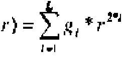
El poder de refracción de la estructura rotacionalmente simétrica en la realización difractiva esThe refractive power of the rotationally symmetric structure in the diffractive embodiment is
Aelonctjra orraxwa = 2 , Aelonctjra orraxwa = 2 ,
$2— A $ 2— A
¡
wl o wl o

siendo wl la longitud de onda de construcción del elemento óptico difractivo y A la longitud de onda de aplicación. En el caso más simple para N=1 y L=1, el poder de refracción total de la lente resulta de un poder de refracción básico refractivo Fbase comparativamente fuerte del sistema básico monofocal y de una parte del poder de refracción relativamente reducida del poder de refracción adicional Fee difractiva en forma de espiral y rotacionalmente simétrico generado de forma difractiva:where wl is the construction wavelength of the diffractive optical element and A is the application wavelength. In the simplest case for N = 1 and L = 1, the total refractive power of the lens results from a comparatively strong refractive basic refractive power Fbase of the monofocal basic system and from a relatively low refractive power part of the lens power. additional refraction Diffractive fee spiral-shaped and rotationally symmetric generated diffractively:
F Ku — = * Fia 33&t*e ' [ /F sKrj3jradt*r»^>a + ' • F s,sol'alct'ri^Aa ] I= F • 0 m3S€ ~ + I F E eEe cre s ta F K u - = * Fia 33 & t * e '[/ F sKrj3jradt * r »^> a + ' • F s , sol'alct'ri ^ Aa ] I = F • 0 m 3S € ~ + I F E e E e cre s ta
Fu = Fm, + [2*, w 4 l + 2 kA wl ' HiplÚ) Fu = Fm, + [2 *, w 4 l + 2 kA wl ' HiplÚ)
En la práctica, el poder de refracción básico de la lente Fbase se fabrica en primer lugar y el poder de refracción adicional en forma de espiral y en forma de estructura FEEdifractiva se aplica a una superficie óptica de la lente básica.In practice, the basic refractive power of the Fbase lens is manufactured first and the additional refractive power in the form of a spiral and in the form of the FEEdifractive structure is applied to an optical surface of the basic lens.
De este modo, mediante la parte difractiva se produce un error de color relativamente pequeño y la lente con el rango de longitud focal ampliado también resulta adecuada para la luz blanca.Thus, the diffractive part produces a relatively small color error and the lens with the extended focal length range is also suitable for white light.
El poder de refracción adicional en forma de espiral y en forma de estructura FEEdifractiva también puede distribuirse por las dos superficies ópticas de la lente.The additional refractive power in the form of a spiral and in the form of the FEEdifractive structure can also be distributed over the two optical surfaces of the lens.
Sin embargo, el término de adición en forma de espiral y de estructura Fee también puede realizarse mediante la creación de un gradiente de índice de refracción en forma de espiral y de estructura AnEE (caso c)). En el documento DE 102009033984 A1 se describe, por ejemplo, cómo se pueden generar propiedades ópticas no homogéneas en un material óptico. En una variante del procedimiento allí descrito también se puede crear una curva de índice de refracción en forma de espiral y en forma de estructura. Las propiedades y la configuración del gradiente del índice de refracción son completamente análogas al planteamiento refractivo y difractivo.However, the addition term in spiral form and Fee structure can also be performed by creating a gradient of refractive index in spiral form and AnEE structure (case c)). DE 102009033984 A1 describes, for example, how non-homogeneous optical properties can be generated in an optical material. In a variant of the method described there, it is also possible to create a spiral-shaped and frame-shaped refractive index curve. The properties and configuration of the refractive index gradient are completely analogous to the refractive and diffractive approach.
El poder de refracción total Ftot resulta del poder de refracción básico Fbase del sistema básico monofocal más el poder de refracción adicional Fee que se pone a disposición a través del aumento del poder de refracción en forma de espiral y en forma de estructura.The total refractive power Ftot results from the basic refractive power Fbase of the basic monofocal system plus the additional refractive power Fee that is made available through the increase in the refractive power in the form of a spiral and in the form of a structure.
El poder de refracción adicional en forma de espiral y en forma de estructura FEE(r, phi) es proporcional a la diferencia del índice de refracción AnEE(r, phi) según la fórmulaThe additional refractive power in spiral form and in structure form FEE (r, phi) is proportional to the difference of the refractive index AnEE (r, phi) according to the formula
A /!ee( r . p h i ) = Anearjaura+ An« ^ ( r . p h i ) - A/Jeanauuf- A/¡«ywa.n» { r . p h i ) * w ( p l i i ) . TO /! ee (r. phi ) = Anearjaura + An «^ (r. phi) - A / Jeanauuf- A / ¡« ywa.n »{ r. phi ) * w ( plii).
La diferencia del índice de refracción AnEE(r, phi) se desarrolla de forma continua desde 0 (en caso de r=0 y phi=0) hasta el máximo aumento del índice de refracción Anespiral máx (en caso de r=D/2 y phi=2n, pudiendo preestablecer la función w(phi) el desarrollo lineal o general antes descrito.The difference in the refractive index AnEE (r, phi) develops continuously from 0 (in the case of r = 0 and phi = 0) to the maximum increase in the refractive index Anespiral max (in the case of r = D / 2 and phi = 2n, the function w (phi) being able to preset the linear or general development described above.
En este caso, Anespiral máx(r, phi) se calcula en analogía con la altura zespiral máx o con la función de fase Faseespiral máx y puede ser tanto positiva como también negativa con respecto al índice de refracción básico n2 de la lente.In this case, Anespiral max (r, phi) is calculated in analogy with the z-spiral height max or with the phase function Phase-spiral max and can be both positive and negative with respect to the basic refractive index n 2 of the lens.
Por lo tanto, el objeto de la presente invención también es cualquier forma mixta de perfil(es) de altura en forma de espiral y/o en forma de Fresnel, de curva(s) de fase en forma de espiral y/o rotacionalmente simétrica(s) y/o de curva(s) de índice de refracción en forma de espiral y/o rotacionalmente simétrica(s) que generan la curva de poder de refracción adicional deseada.Therefore, the object of the present invention is also any mixed form of spiral-shaped and / or Fresnel-shaped height profile (s), spiral-shaped and / or rotationally symmetric phase curve (s). Spiral and / or rotationally symmetric refractive index curve (s) and / or curve (s) that generate the desired additional refractive power curve.
El perfil de altura y/o la curva de fase pueden disponerse repartidos o combinados en una de las superficies ópticas y/o en las dos superficies ópticas de una lente.The height profile and / or the phase curve can be arranged distributed or combined on one of the optical surfaces and / or on the two optical surfaces of a lens.
La invención se describe a continuación mediante figuras. Se muestra en la(s):The invention is described below by means of figures. Shown in (s):
Figura 1 una lente "gruesa" con un rango de longitud focal ampliado en la vista lateral según una solución descrita en el documento DE 102011 101 899 A1 y en la que se basa la invención,Figure 1 a "thick" lens with an enlarged focal length range in the side view according to a solution described in DE 102011 101 899 A1 and on which the invention is based,
Figura 2 una lente "fina" con un rango de longitud focal ampliado según la invención en la vista lateral,Figure 2 a "fine" lens with an extended focal length range according to the invention in the side view,
Figura 3 una representación esquemática del procedimiento y de los pasos de cálculo que dan lugar al dimensionamiento y a la fabricación de la lente "fina",Figure 3 a schematic representation of the procedure and the calculation steps that lead to the dimensioning and manufacturing of the "fine" lens,
Figura 4 una representación de una parte del poder de refracción en forma de espiral,Figure 4 a representation of a part of the refractive power in the form of a spiral,
Figura 5 una representación de una parte conforme a Fresnel y rotacionalmente simétrica del poder de refracción, Figura 6 una representación de la parte conforme a Fresnel añadida en forma de espiral y rotacionalmente simétrica del poder de refracción, Figure 5 a representation of a rotationally symmetric Fresnel-conforming part of the refractive power, Figure 6 a representation of the Fresnel-conforming part added in a spiral and rotationally symmetric refractive power,
Figuras 7 a 10 una representación de la parte conforme a Fresnel añadida en forma de espiral y rotacionalmente simétrica del poder de refracción, aumentando la intensidad de la parte en forma de espiral de figura en figura, Figura 11 una representación de una estructura difractiva en forma de espiral que genera la parte del poder de refracción en forma de espiral,Figures 7 to 10 a representation of the Fresnel-shaped part added in the form of a spiral and rotationally symmetrical of the refractive power, increasing the intensity of the spiral-shaped part from figure to figure, Figure 11 a representation of a diffractive structure in the form spiral that generates the part of the refractive power in the form of a spiral,
Figura 12 una representación de una estructura de anillos difractiva y rotacionalmente simétrica,Figure 12 a representation of a rotationally symmetric diffractive ring structure,
Figura 13 una representación de la estructura difractiva añadida en forma de espiral y de la estructura de anillos difractiva y rotacionalmente simétrica que corresponde a la parte del poder de refracción según la figura 6, Figura 14 una representación esquemática de una lente intraocular en el ojo,Figure 13 a representation of the diffractive structure added in the form of a spiral and of the diffractive and rotationally symmetric ring structure corresponding to the part of the refractive power according to figure 6, Figure 14 a schematic representation of an intraocular lens in the eye,
Figura 15 un sistema óptico de una cámara con una lente "gruesa",Figure 15 an optical system of a camera with a "thick" lens,
Figura 16 un sistema óptico de una cámara con una lente "fina" con el rango de longitud focal ampliado.Figure 16 an optical system of a camera with a "fine" lens with the widened focal length range.
La figura 1 muestra una lente "gruesa" 1 con un rango de longitud focal ampliado según el documento DE 102011 101899 A1. Se muestra una vista lateral con la representación del perfil de altura refractivo en forma de espiral zespiral(r, phi) que genera la distribución del poder de refracción en forma de espiral Fespiral(r, phi). Esta lente 1 se determina en principio por medio de su sistema básico con el radio R1 de la primera superficie óptica 2' y con el radio R2 para la superficie de base calculada 3', así como por medio del grosor de lente d1 y del índice de refracción n2. Estos parámetros se determinan para un aumento básico previsto. A la forma calculada de la superficie de base 3' con el radio R2 se le añade un grosor adicional de material z, siendo el grosor adicional de material z=0 mm si phi=0, aumentando en tal caso de forma constante y presentando un valor máximo en el rango de milímetros si phi=2 n. En la práctica, el valor máximo se alcanzará un poco antes del ángulo azimutal phi=2 n, a fin de realizar una transición constante, aunque muy pronunciada, de vuelta al valor cero para phi=0, como se indica mediante la curva discontinua identificada con la referencia 4a.Figure 1 shows a "thick" lens 1 with an extended focal length range according to DE 102011 101899 A1. A side view is shown with the representation of the refractive height profile in the form of a z-spiral (r, phi) that generates the distribution of the refractive power in the form of a F-spiral (r, phi). This lens 1 is determined in principle by means of its basic system with the radius R 1 of the first optical surface 2 'and with the radius R 2 for the calculated base surface 3', as well as by means of the lens thickness d 1 and the refractive index n 2 . These parameters are determined for an expected base increase. An additional material thickness z is added to the calculated shape of the base surface 3 'with radius R 2 , the additional material thickness z = 0 mm if phi = 0, in this case increasing constantly and presenting a maximum value in the range of millimeters if phi = 2 n. In practice, the maximum value will be reached a little before the azimuth angle phi = 2 n, in order to make a constant, albeit very steep, transition back to zero for phi = 0, as indicated by the identified dashed curve with reference 4a.
Como ejemplo se indican los parámetros para una lente:As an example the parameters for a lens are indicated:
R1= -15,1411 mm de radio a fabricarR 1 = -15.1411 mm radius to be manufactured
R2= 22,3164 mm de radio calculadoR 2 = 22.3164 mm radius calculated
d1= 0,8 mmd 1 = 0.8 mm
n1= 1 (índice de refracción fuera de la lente)n 1 = 1 (index of refraction outside the lens)
n2= 1,56 (índice de refracción del medio de lente)n 2 = 1.56 (refractive index of the lens medium)
resultando así de la fórmulathus resulting from the formula
ll

la distancia focal de la "lente básica" con un valor de 16,233 mm.the focal length of the "basic lens" with a value of 16,233 mm.
A la superficie de base calculada con el radio R2= 22,3164 mm se le añade un "aumento helicoidal" lineal de acuerdo con la fórmulaTo the base surface calculated with the radius R 2 = 22.3164 mm a linear "helical increase" is added according to the formula
Zwmi (r,ph¡) = z esDiraimáx ( r ) * w (p A 0 -< i* r l ' tí =Zwmi ( r, ph¡) = z isDiraimáx (r) * w (p A 0 - <i * rl 'tí =
2n2n
como un perfil de altura continuo en forma de espiral que se desarrolla linealmente, resultando la superficie óptica 4'. Con c1 =-0,013 se obtiene una adición en forma de espiral que aumenta la distancia focal en el aire hasta 20,57 mm, lo que corresponde a 3,5 dpt.as a continuous spiral-shaped height profile that develops linearly, resulting in the optical surface 4 '. With c 1 = -0.013, a spiral-shaped addition is obtained that increases the focal length in air to 20.57 mm, which corresponds to 3.5 dpt.
La figura 2 muestra una lente "fina" 5 según la invención que presenta radios R3 y R4 más planos en comparación con la lente 1 mostrada en la figura 1 y cuyo grosor central d2 es más fino, obteniéndose aproximadamente los mismos parámetros de reproducción de la lente según la figura 1: Con un poder de refracción básico de aproximadamente 61 dpt se logra un poder de refracción adicional de 3,5 dpt. La lente "fina" 5 presenta la característica especial de que la adición en forma de espiral contiene un componente de Fresnel rotacionalmente simétrico. Este componente de Fresnel realiza una parte del poder de refracción que la lente "gruesa" 1 según la figura 1 obtiene de los radios R1 y R2, así como del grosor de lente d1, de manera que los radios R3 y R4 de la nueva lente 5 sean más planos y de manera que su grosor central d2 sea comparativamente menor.Figure 2 shows a "thin" lens 5 according to the invention that has radii R 3 and R 4 flatter compared to lens 1 shown in Figure 1 and whose central thickness d 2 is thinner, obtaining approximately the same parameters of reproduction of the lens according to FIG. 1: With a basic refractive power of approximately 61 dpt an additional refractive power of 3.5 dpt is achieved. The "fine" lens 5 has the special feature that the spiral-shaped addition contains a rotationally symmetrical Fresnel component. This Fresnel component produces a part of the refractive power that the "thick" lens 1 according to figure 1 obtains from the radii R 1 and R 2 , as well as from the lens thickness d 1 , so that the radii R 3 and R 4 of the new lens 5 are flatter and so that their central thickness d 2 is comparatively less.
El procedimiento para el dimensionamiento de la nueva lente "fina" 5 según la invención se explica por medio de la figura 3.The procedure for sizing the new "thin" lens 5 according to the invention is explained by means of figure 3.
El punto de partida es la lente "gruesa" 1 representada en la fila superior de la figura 3 y que sólo se calcula. La misma se compone del sistema básico refractivo, con los radios R1 y R2 así como con el grosor central d1 (representado a la izquierda), y de la parte del poder de refracción en forma de espiral que se realiza teóricamente mediante el perfil de altura zesp¡rai(r, phi) en el radio R2 (representado a la derecha). A continuación, se representa en la parte inferior la división del poder de refracción del sistema básico refractivo en una nueva lente "fina" 5, con los radios R3 y R4 así como con el grosor central d2, y en una parte del poder de refracción en forma de Fresnel rotacionalmente simétrica zFresnel(r).The starting point is the "thick" lens 1 represented in the top row of figure 3 and which is only calculated. It is made up of the basic refractive system, with the radii R 1 and R 2 as well as the central thickness d 1 (represented on the left), and the part of the refractive power in the form of a spiral that is carried out theoretically by means of the profile of height zesp¡rai (r, phi) at radius R 2 (pictured on the right). Next, the division of the refractive power of the basic refractive system in a new "thin" lens 5 is represented in the lower part, with the radii R 3 and R 4 as well as with the central thickness d 2 , and in a part of the rotationally symmetric Fresnel-shaped refractive power zFresnel (r).
En la fila inferior se representa la adición de la parte del poder de refracción en forma de Fresnel zFresnel(r) y de la parte en forma de espiral zespiral(r, phi) a un poder de refracción adicional en forma de espiral y en forma de Fresnel Fef. El perfil de altura zEF(r, phi) = zespiral(r, phi) zFresnel(r) se añade al radio sólo calculado R4 de la lente básica con el perfil de altura zbase.The bottom row represents the addition of the part of the Fresnel-shaped refractive power zFresnel (r) and of the spiral-shaped part zespiral (r, phi) to an additional refractive power in the form of a spiral and in the form by Fresnel Fef. The height profile zEF (r, phi) = zspiral (r, phi) zFresnel (r) is added to the only calculated radius R 4 of the basic lens with the height profile zbase.
Ahora se fabrica una lente con el radio R3 con un grosor central d2 y con un perfil de altura zEF(r, phi) sobre el radio calculado R4. El perfil de altura correspondiente a fabricar para la superficie óptica 4 resulta como sigueNow a lens with radius R 3 is manufactured with a central thickness d 2 and with a height profile zEF (r, phi) over the calculated radius R4. The corresponding height profile to be manufactured for the optical surface 4 is as follows

La figura 4 muestra sólo la parte del poder de refracción en forma de espiral Fespiral de la lente como perfil de altura zespiral(r, phi). La figura 5 muestra sólo la parte del poder de refracción conforme a Fresnel y rotacionalmente simétrica FFresnel de la lente como un perfil de altura zFresnel(r). La representación en la figura 6 muestra el resultado de una adición de la parte del poder de refracción en forma de espiral y de la parte del poder de refracción conforme a Fresnel y rotacionalmente simétrica como un perfil de altura zEF(r, phi) que representa la parte del poder de refracción en forma de espiral y en forma de Fresnel Fef.Figure 4 shows only the part of the F-spiral-shaped refractive power of the lens as the z-spiral height profile (r, phi). Figure 5 shows only the part of the fresnel-conforming and rotationally symmetric FFresnel refractive power of the lens as a height profile zFresnel (r). The representation in figure 6 shows the result of an addition of the part of the refractive power in spiral form and of the part of the refractive power according to Fresnel and rotationally symmetric as a height profile zEF (r, phi) that represents the part of the refractive power in the form of a spiral and in the form of Fresnel Fef.
Este perfil de altura se añade al perfil de altura zbase de la superficie de base calculada 3 con el radio R4 y se fabrica en la lente a producir.This height profile is added to the height profile zbase of the calculated base surface 3 with the radius R4 and manufactured into the lens to be produced.
Las figuras 7 a 10 muestran respectivamente una representación de la parte sumada del poder de refracción en forma de espiral, rotacionalmente simétrica y conforme a Fresnel Fef, aumentando la intensidad de la parte en forma de espiral de figura en figura de 1 dpt a 3,5 dpt.Figures 7 to 10 show respectively a representation of the summed part of the refractive power in the form of a spiral, rotationally symmetrical and according to Fresnel Fef, increasing the intensity of the part in the form of a spiral from figure to figure from 1 dpt to 3, 5 dpt.
A continuación, en las figuras 11 a 13 se muestra que un poder de refracción adicional en forma de espiral y en forma de estructura de la lente Fee se transfiere partiendo del planteamiento refractivo (donde el poder de refracción adicional en forma de estructura se realiza mediante una estructura de Fresnel) de forma completamente análoga a un planteamiento difractivo.Next, in Figures 11 to 13 it is shown that an additional refractive power in the form of a spiral and in the form of a structure of the Fee lens is transferred from the refractive approach (where the additional refractive power in the form of a structure is realized by a Fresnel structure) completely analogous to a diffractive approach.
La figura 11 muestra esquemáticamente una estructura difractiva en forma de espiral que genera la parte del poder de refracción en forma de espiral Fespiral difractiva. La figura 12 muestra esquemáticamente una estructura de anillos difractiva rotacionalmente simétrica que genera la parte del poder de refracción en forma de estructura Festructura difractiva. La figura 13 muestra el resultado de una adición de las dos estructuras difractivas. Esta superposición de la estructura difractiva en forma de espiral y de la estructura de anillos difractiva rotacionalmente simétrica da como resultado una parte de poder de refracción en forma de espiral y en forma de estructura Fee que en su efecto corresponde a la parte del poder de refracción en forma de espiral y en forma de Fresnel Fef que se representa esquemáticamente en la figura 6 mediante el perfil de altura en forma de espiral y en forma de Fresnel zef.Figure 11 schematically shows a diffractive spiral-shaped structure that generates the part of the refractive power in the form of a diffractive spiral F-spiral. Figure 12 schematically shows a rotationally symmetric diffractive ring structure that generates the part of the refractive power in the form of a Diffractive Fracture structure. Figure 13 shows the result of an addition of the two diffractive structures. This superposition of the spiral-shaped diffractive structure and the rotationally symmetric diffractive ring structure results in a part of the refractive power in the form of a spiral and in the form of a Fee structure, which in its effect corresponds to the part of the refractive power. Spiral-shaped and Fresnel-shaped Fef which is schematically represented in Figure 6 by the spiral-shaped and Fresnel-shaped height profile zef.
La figura 14 muestra una representación esquemática de una lente intraocular 11 que se implanta en el ojo como una lente de longitud focal ampliada "fina" 5. En el ejemplo, ésta reemplaza el cristalino natural del ojo y se encuentra en el trayecto de la luz entre la córnea 12 y la retina 14 en el humor acuoso 13.Figure 14 shows a schematic representation of an intraocular lens 11 that is implanted in the eye as a "fine" extended focal length lens 5. In the example, it replaces the natural lens of the eye and is in the path of light. between the cornea 12 and the retina 14 in the aqueous humor 13.
La lente intraocular 11 tiene una primera superficie óptica esférica 2, así como la segunda superficie óptica 4 que soporta la forma de espiral y la forma de estructura.The intraocular lens 11 has a first spherical optical surface 2, as well as the second optical surface 4 that supports the spiral shape and the frame shape.
En un primer ejemplo, la lente intraocular 11 con el rango de longitud focal ampliado presenta los siguientes parámetros para el sistema básico:In a first example, the intraocular lens 11 with the extended focal length range has the following parameters for the basic system:
Los radios de base de la lente portadora son el radio de lente fabricado R3=-20 mm y el radio de lente calculado R4=+20 mm de la superficie de base 3. A la superficie de base 3 se le añade el perfil de altura en forma de espiral y en forma de Fresnel zEF(r, phi), fabricándose el mismo como superficie 4.The base radii of the carrier lens are the manufactured lens radius R3 = -20 mm and the calculated lens radius R4 = + 20 mm from the base surface 3. The height profile is added to the base surface 3 spiral-shaped and Fresnel-shaped zEF (r, phi), manufacturing the same as surface 4.
El poder de refracción de la parte conforme a Fresnel en el poder de refracción básico de la lente resulta del perfil de altura de una estructura de FresnelThe refractive power of the Fresnel-conforming part in the basic refractive power of the lens results from the height profile of a Fresnel structure
/./.
Z í w 0 " ) = 2 / , * r 'Z í w 0 ") = 2 /, * r '
í =1 J t = 1 J
resultando para L=2 los coeficientes del polinomio de Fresnel rotacionalmente simétrico e1=0,036 y e2=-0,00018398. El poder de refracción del poder de refracción adicional en forma de espiral de la lente resulta del perfil de alturaresulting for L = 2 the coefficients of the rotationally symmetric Fresnel polynomial e1 = 0.036 and e2 = -0.00018398. The refractive power of the additional spiral-shaped refractive power of the lens results from the height profile

resultando para N=1 el coeficiente del polinomio de espiral c1=0,025. resulting for N = 1 the coefficient of the spiral polynomial c1 = 0.025.
Así resultaSo it turns out

La profundidad de diente del elemento conforme a Fresnel p se elige con 0,1 mm, resultando por lo tanto el poder de refracción adicional en forma de espiral y conforme a Fresnel a través de la función de módulo mod(zEF(r, phi), p). En este caso se supone que el radio de la córnea es R5=7,814 mm y la constante cónica K=-0,26. La distancia entre la córnea 12 y el lado delantero de la lente R4 es de 4,12 mm, el grosor de lente de la lente intraocular es d2 = 0,65 mm y la distancia desde el lado delantero de la lente R2 hasta la retina 14 es de 18,1 mm. Como material se utiliza Benz 25 con un índice de refracción del medio de lente n2= 1,56.The tooth depth of the Fresnel-compliant element p is chosen to be 0.1 mm, thus resulting in the additional refractive power in spiral and Fresnel-compliant form through the modulus function mod (zEF (r, phi) , p). In this case it is assumed that the radius of the cornea is R5 = 7.814 mm and the conic constant K = -0.26. The distance between the cornea 12 and the front side of the lens R 4 is 4.12 mm, the lens thickness of the intraocular lens is d 2 = 0.65 mm, and the distance from the front side of the lens R 2 up to retina 14 is 18.1 mm. The material used is Benz 25 with a refractive index of the lens medium n 2 = 1.56.
El índice de refracción fuera de la lente, del humor acuoso 13, es m = 1,33.The refractive index outside the lens of aqueous humor 13 is m = 1.33.
En comparación, la lente intraocular descrita en el documento DE102011 101 899, allí figura 4, tiene los siguientes parámetros:In comparison, the intraocular lens described in document DE102011 101 899, there figure 4, has the following parameters:
R1= -15,1411 mm (primera superficie óptica fabricada 2)R 1 = -15.1411 mm (first fabricated optical surface 2)
R2= 22,3164 mm (superficie de base calculada 3)R 2 = 22.3164 mm (calculated base area 3)
Grosor de lente d1 = 0,8 mm.Lens thickness d 1 = 0.8 mm.
Como resultado, la nueva lente según la invención de acuerdo con el ejemplo de la figura 14 es 0,15 mm más fina, lo que se debe a que el radio R3 es más plano que el radio R1.As a result, the new lens according to the invention according to the example of figure 14 is 0.15 mm thinner, which is because the radius R 3 is flatter than the radius R 1 .
En un segundo ejemplo en relación con la figura 14, la lente intraocular 11 con el rango de longitud focal ampliado tiene los siguientes parámetros para una realización difractiva del poder de refracción adicional en forma de espiral y en forma de estructura Fee en una superficie óptica de la lente básica:In a second example in relation to figure 14, the intraocular lens 11 with the extended focal length range has the following parameters for a diffractive realization of the additional refractive power in the form of a spiral and in the form of a Fee structure on an optical surface of the basic lens:
córnea: radio R5 =7,814 mm, constante de cono asférica K=-0,26,cornea: radius R 5 = 7.814 mm, aspherical cone constant K = -0.26,
radios de base de la lente R3 =R4 = /- 20,0 mm (esférica), la distancia de la córnea R5 a la superficie óptica acabada 4 con el radio R4 es de 4,12 mm,base radii of lens R 3 = R4 = / - 20.0 mm (spherical), the distance from cornea R 5 to finished optical surface 4 with radius R 4 is 4.12 mm,
el grosor de la lente intraocular es d2 = 0,65 mm y la distancia de la superficie óptica acabada 2 con el radio R3 hasta la retina es de 18,5 mm.the thickness of the intraocular lens is d 2 = 0.65 mm and the distance from the finished optical surface 2 with radius R 3 to the retina is 18.5 mm.
El material utilizado para la lente intraocular es "Benz25". El diámetro de la lente intraocular es de 6 mm. Con estos parámetros se describe el sistema básico refractivo de la lente y se determina su poder de refracción Fbase. El poder de refracción adicional en forma de espiral Fespiral y el poder de refracción adicional en forma de estructura generan como una distribución del poder de refracción difractiva en forma de espiral y en forma de estructura Fee con un elemento óptico difractivo aplicado a la superficie con el radio R4. Por consiguiente, el poder de refracción total de la lente intraocular 11 resulta como sigueThe material used for the intraocular lens is "Benz25". The diameter of the intraocular lens is 6 mm. With these parameters the basic refractive system of the lens is described and its refractive power Fbase is determined. The F-spiral-shaped additional refractive power and the structure-shaped additional refractive power generate as a spiral-shaped and fee-structure-shaped diffractive refractive power distribution with a diffractive optical element applied to the surface with the radius R 4 . Consequently, the total refractive power of the intraocular lens 11 results as follows
b ■& b ■ & Mse d - Mse d - b b EEürrKtwa — ^ see ^ EEürrKtwa - ^ see ^ egrjsvra egrjsvra o rrxs te or rrxs you b b esoiraiorrsste jesoiraiorrsste j
Expresado como una función de fase resulta el poder de refracción adicional en forma de espiral y en forma de estructuraExpressed as a phase function, the additional refractive power in the form of a spiral and in the form of a structure results.


-- x resulta - x results
FaseEE ( 
y la función de fase reducida and the reduced phase function

siendo phi=0... 2n (ángulo azimutal), r = altura radial en la lente y wl la longitud de onda de construcción del elemento difractivo (longitud de onda de fabricación sintética).where phi = 0 ... 2n (azimuthal angle), r = radial height in the lens and wl the construction wavelength of the diffractive element (synthetic manufacturing wavelength).
En relación con los coeficientes de la parte conforme a Fresnel y rotacionalmente simétrica, que aquí está presente como la parte simétrica de un elemento óptico difractivo, se determina que: g1=0,006109 y g2=-4,92E-5.In relation to the coefficients of the rotationally symmetric Fresnel-conforming part, which is present here as the symmetric part of a diffractive optical element, it is determined that: g 1 = 0.006109 and g2 = -4.92E-5.
En relación con el coeficiente de la parte en forma de espiral del elemento óptico difractivo se aplica k1=-0,003. La profundidad de perfil del elemento óptico difractivo es h = 0,0043 mm.Relative to the coefficient of the spiral-shaped part of the diffractive optical element, k1 = -0.003 applies. The profile depth of the diffractive optical element is h = 0.0043 mm.
En un tercer ejemplo, la lente intraocular 11 con el rango de longitud focal ampliado tiene los siguientes parámetros para una realización difractiva del poder de refracción adicional Fee, repartido en las dos superficies ópticas 2 y 4 de la lente básica refractiva 3:In a third example, the intraocular lens 11 with the extended focal length range has the following parameters for a diffractive realization of the additional refractive power Fee, distributed over the two optical surfaces 2 and 4 of the basic refractive lens 3:
radio de córnea R5=7,814 mm, constante de cono asférica K=-0,26)corneal radius R5 = 7.814 mm, aspheric cone constant K = -0.26)
Los radios de base de la lente intraocular son R3=R4 = /- 20,0 mm (esférico). Otros parámetros son: la distancia desde el radio de córnea R5 hasta la superficie óptica 4 con el radio R4 es de 4,12 mm, el grosor central es d2 = 0,65 mm, la distancia desde la superficie óptica 2 con el radio R3 hasta la retina es de 18,5 mm, el material de lente es "Benz25" y el diámetro de la lente intraocular es de 6 mm.The base radii of the intraocular lens are R3 = R4 = / - 20.0 mm (spherical). Other parameters are: the distance from the corneal radius R5 to the optical surface 4 with the radius R4 is 4.12 mm, the central thickness is d2 = 0.65 mm, the distance from the optical surface 2 with the radius R3 up to the retina is 18.5mm, the lens material is "Benz25", and the diameter of the intraocular lens is 6mm.
En este ejemplo, a cada una de las superficies ópticas 2 y 4 se le aplica respectivamente un elemento óptico difractivo. In this example, each of the optical surfaces 2 and 4 is respectively applied a diffractive optical element.
Aquí, el poder de refracción se distribuye de manera que la parte del poder de refracción en forma de espiral Fespiral esté situada en la superficie óptica con el radio R4 y de manera que la parte del poder de refracción en forma de estructura y rotacionalmente simétrica Festructura esté situada en el radio R3.Here, the refractive power is distributed so that the part of the refractive power in the form of a spiral F-spiral is located on the optical surface with the radius R4 and so that the part of the refractive power in the form of a structure and rotationally symmetrical. is located in radius R 3 .
Con L=2, N=1 yWith L = 2, N = 1 and
W(plti) pfü W ( plti) pfü
2ít2it
resultaresult
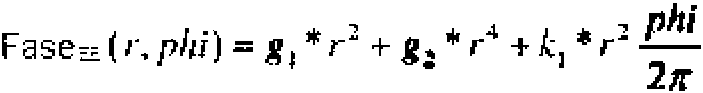
y resulta la función de fase reducida como sigueand the reduced phase function results as follows
Fases(/•,/?;»') Parte Faseg (r.phi) Phases (/ •, / ?; »') Part Phaseg ( r.phi)
F a s e tE reojMH ( F a s e tE reojMH ( r, phi) r, phi) ■■
wl entera n7 wl integer n7
siendo phi=0... 2n (ángulo azimutal), r = altura radial en la lente y wl la longitud de onda de construcción del elemento difractivo (longitud de onda de fabricación sintética).where phi = 0 ... 2n (azimuthal angle), r = radial height in the lens and wl the construction wavelength of the diffractive element (synthetic manufacturing wavelength).
Al elemento óptico difractivo aplicado a la superficie óptica 4 se le aplica lo siguiente:The following applies to the diffractive optical element applied to the optical surface 4:
g1=0, así como g2=0 y k1=-0,003.g1 = 0, as well as g2 = 0 and k1 = -0.003.
La profundidad de perfil del elemento óptico difractivo es h = 0,0043 mm.The profile depth of the diffractive optical element is h = 0.0043 mm.
Al elemento óptico difractivo aplicado a la superficie óptica 2 se le aplica lo siguiente:The following applies to the diffractive optical element applied to the optical surface 2:
g1=0,0065, así como g2=1,8975 E-4 y k1=0.g1 = 0.0065, as well as g2 = 1.8975 E-4 and k 1 = 0.
La profundidad de perfil del elemento óptico difractivo es h = 0,0043 mm.The profile depth of the diffractive optical element is h = 0.0043 mm.
La figura 15 muestra un sistema óptico de una cámara según la figura 3 del documento DE 102011 101 899 A1 con una lente "gruesa" 1 que presenta el rango de longitud focal ampliado. Al poder de refracción básico, resultante de los radios R1, R2 , del índice de refracción n2 y del grosor central d1 de la lente calculada, se le añade una parte de poder de refracción adicional en forma de una parte de poder de refracción en forma de espiral. Esta parte de poder de refracción en forma de espiral se añade como perfil de altura zespiral al perfil de altura de la superficie de base calculada 3' y se fabrica en la práctica como una segunda superficie óptica 4'.FIG. 15 shows an optical system of a camera according to FIG. 3 of DE 102011 101 899 A1 with a "thick" lens 1 having the widened focal length range. To the basic refractive power, resulting from the radii R 1 , R 2 , the refractive index n 2 and the central thickness d 1 of the calculated lens, an additional refractive power part is added in the form of a power part of refraction in the form of a spiral. This spiral-shaped refractive power part is added as a z-spiral height profile to the height profile of the calculated base surface 3 'and is manufactured in practice as a second optical surface 4'.
La parte del poder de refracción en forma de espiral también puede fabricarse sin embargo en forma difractiva como un elemento óptico difractivo en una o ambas superficies ópticas de la lente con el poder de refracción básico. Alternativamente, la parte del poder de refracción en forma de espiral también puede fabricarse como un gradiente de índice de refracción dentro de la lente con el poder de refracción básico. También está prevista cualquier forma mixta. The spiral-shaped part of the refractive power can, however, also be produced in diffractive form as a diffractive optical element on one or both optical surfaces of the lens with the basic refractive power. Alternatively, the spiral shaped part of the refractive power can also be manufactured as a refractive index gradient within the lens with the basic refractive power. Any mixed form is also envisaged.
La figura 16 muestra un sistema óptico de una cámara con una lente "fina" 5 según la invención que presenta el rango de longitud focal ampliado. En el ejemplo, al poder de refracción básico de la lente calculada se le añade una parte de poder de refracción adicional en forma de un perfil de altura en forma de espiral y en forma de Fresnel zef. El perfil de altura se añade al perfil de altura de la superficie de base calculada 3 con el radio R4 y se fabrica como una segunda superficie óptica 4. La parte del poder de refracción en forma de espiral y en forma de Fresnel también puede realizarse total o parcialmente mediante un elemento óptico difractivo en la superficie óptica de la lente básica (o de forma distribuida en ambas superficies ópticas) o mediante un gradiente de índice de refracción en el material de la lente. A la lente "fina" 5 le sigue, en la dirección de propagación de la luz, una lente asférica 6 con superficies ópticas 17 y 18 y, a continuación, un filtro 15 y un sensor 7.Figure 16 shows an optical system of a camera with a "fine" lens 5 according to the invention exhibiting the extended focal length range. In the example, an additional refractive power part is added to the basic refractive power of the calculated lens in the form of a spiral-shaped and Fresnel-shaped height profile zef. The profile of height is added to the height profile of the calculated base surface 3 with the radius R 4 and manufactured as a second optical surface 4. The part of the refractive power in the spiral form and in the Fresnel form can also be fully or partially realized by a diffractive optical element on the optical surface of the basic lens (or in a distributed manner on both optical surfaces) or by a refractive index gradient in the lens material. The "fine" lens 5 is followed, in the direction of light propagation, by an aspherical lens 6 with optical surfaces 17 and 18, followed by a filter 15 and a sensor 7.
La lente "fina" 5 tiene por el lado del objeto una primera superficie óptica 2 con el radio R3. En el lado de la imagen se conforma la segunda superficie óptica 4, cuyo perfil de altura resulta del perfil de altura zbase del radio calculado R4 y del perfil de altura en forma de espiral y en forma de Fresnel zEF(r, phi).The "fine" lens 5 has on the object side a first optical surface 2 with radius R 3 . On the image side, the second optical surface 4 is formed, the height profile of which results from the height profile zbase of the calculated radius R 4 and the spiral-shaped and Fresnel-shaped height profile zEF (r, phi).
Como ejemplo se muestra un objetivo de teléfono móvil con una distancia focal de 5,61 mm que tiene una longitud constructiva de 6,1 mm y una apertura de 1:2,8.As an example, a mobile phone lens with a focal length of 5.61 mm is shown which has a body length of 6.1 mm and an aperture of 1: 2.8.
Las superficies ópticas 2, 17 y 18 de las lentes 5 y 6 tienen una forma básica asférica rotacional.The optical surfaces 2, 17 and 18 of the lenses 5 and 6 have a rotational aspherical basic shape.
Lente 5: Grosor de lente d2 = 1,21 mm, el material es ZeonexLens 5: Lens thickness d 2 = 1.21mm, material is Zeonex
Superficie óptica 2: R3 = 1,482 mm convexoOptical surface 2: R 3 = 1,482 mm convex
Coeficientes asféricos:Aspherical coefficients:
K = 0,04649K = 0.04649
A = -0,698748E-03A = -0.698748E-03
B = 0,987484E-03B = 0.987484E-03
C = -0,119379E-03C = -0.119379E-03
D =-0,104254E-02D = -0.104254E-02
E = 0,323245E-03E = 0.323245E-03
La superficie de base esférica cóncava no fabricada 3 presenta un radio calculado R4 = 6,303 mm. La curva del poder de refracción en forma de espiral y en forma de Fresnel se añade en forma de un perfil de altura Zef al perfil de altura zbase de esta superficie de base 3. Este perfil de altura se fabrica a continuación en la lente a acabar. En el ejemplo, el coeficiente del polinomio en forma de espiral es c1 = -0,00268 y el coeficiente de la parte de Fresnel rotacionalmente simétrica es e1 = 0,03.The unmanufactured concave spherical base surface 3 has a calculated radius R 4 = 6.303 mm. The spiral-shaped and Fresnel-shaped refractive power curve is added in the form of a height profile Zef to the height profile zbase of this base surface 3. This height profile is then manufactured on the lens to be finished . In the example, the coefficient of the spiral polynomial is c 1 = -0.00268 and the coefficient of the rotationally symmetric Fresnel part is e 1 = 0.03.
La parte del poder de refracción adicional en forma de espiral se calcula como sigueThe part of the additional refractive power in the form of a spiral is calculated as follows
/'"espiral = / '"spiral = 2 k] * r 22 k] * r 2
2 K2K
y la parte de Fresnel adicional rotacionalmente simétrica se calcula conand the rotationally symmetric additional Fresnel part is calculated with
Y el poder de refracción total resulta como sigueAnd the total refractive power turns out as follows
* lot “ / D3EC ~t" /* E-S - k 33 ^ f l r ( y t c ¡ 4 " f «piral* lot “/ D3EC ~ t" / * ES - k 33 ^ f lr ( ytc ¡ 4 "f« piral

El poder de refracción adicional añadido a la superficie de base 3 esThe additional refractive power added to base surface 3 is

o descrito como perfil de alturaor described as height profile
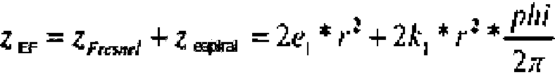
La profundidad de diente de los surcos de Fresnel es de 0,008 mm.The tooth depth of the Fresnel grooves is 0.008 mm.
La lente 6 tiene un grosor de 3,0 mm, el material es policarbonato.Lens 6 is 3.0mm thick, the material is polycarbonate.
La superficie óptica 17 tiene un radio R6 = -3,075 mm con los coeficientes asféricos:The optical surface 17 has a radius R6 = -3.075 mm with the aspherical coefficients:
K = 11,058298 K = 11.058298
A = -0,623991 E-01A = -0.623991 E-01
B = -0,926325E-02B = -0.926325E-02
C = 0,244030E-01C = 0.244030E-01
D = -0,125809E+00D = -0.125809E + 00
E = 0,345714E-01E = 0.345714E-01
F = -0,101087E-01F = -0.101087E-01
G = -0,221418E-15G = -0.221418E-15
H = -0,409672E-17H = -0.409672E-17
J = 0,991703E-20J = 0.991703E-20
La superficie óptica 18 tiene el radio R7 = 44,1377 mm (convexo) con los coeficientes asféricos:The optical surface 18 has the radius R 7 = 44.1377 mm (convex) with the aspherical coefficients:
K = -0,238656e57K = -0.238656e57
A = -0,171783E-01A = -0.171783E-01
B = 0,462293E-03B = 0.462293E-03
C = -0,823963E-03C = -0.823963E-03
D = 0,227317E-03D = 0.227317E-03
E = -0,108925E-04E = -0.108925E-04
F = -0,474572E-05F = -0.474572E-05
G = 0,385353E-06G = 0.385353E-06
H = 0,475909E-07H = 0.475909E-07
J = -0,466662E-08J = -0.466662E-08
La distancia entre la lente 5 y la lente 6 es de 0,75 mm, la distancia entre la lente 6 y el filtro 15 es de 0,4 mm y la distancia del filtro 15 al plano de imagen del detector 7 es de 0,4 mm, siendo el grosor de filtro también de 0,4 mm. El objetivo proporciona un rango de longitud focal simultáneo desde 330 mm hasta el infinito.The distance between lens 5 and lens 6 is 0.75mm, the distance between lens 6 and filter 15 is 0.4mm, and the distance from filter 15 to the image plane of detector 7 is 0, 4 mm, the filter thickness being also 0.4 mm. The lens provides a simultaneous focal length range from 330mm to infinity.
La longitud constructiva del objetivo es sólo de 6,1 mm y por lo tanto 0,7 mm más corta que la descrita en los ejemplos de la figura 3 en el documento DE 102011 101 899 A1.The overall length of the objective is only 6.1 mm and therefore 0.7 mm shorter than that described in the examples of figure 3 in DE 102011 101 899 A1.
En este caso, la acromatización del objetivo se apoyó especialmente en la elección adecuada de los coeficientes c y e antes del término cuadrático.In this case, the achromatization of the objective relied especially on the adequate choice of the coefficients c and e before the quadratic term.
Lista de referenciasList of references
1 Lente "gruesa"1 "thick" lens
2 Primera superficie óptica acabada (esférica, asférica, radialmente simétrica, de forma libre) de una lente "fina" 2' Superficie óptica de una lente "gruesa"2 First finished optical surface (spherical, aspherical, radially symmetrical, free-form) of a "thin" lens 2 'Optical surface of a "thick" lens
3 Superficie de base calculada de la lente "fina" (esférica, asférica, radialmente simétrica, superficie de forma libre)3 Calculated base area of "fine" lens (spherical, aspherical, radially symmetrical, free-form surface)
3' Segunda superficie óptica calculada de la lente "gruesa"3 'Second calculated optical surface of the "thick" lens
4 Segunda superficie óptica acabada de la lente "fina" (esférica, asférica, radialmente simétrica, superficie de forma libre, superficie en forma de espiral y en forma de estructura)4 Second finished optical surface of the "fine" lens (spherical, aspherical, radially symmetrical, free-form surface, spiral-shaped and frame-shaped surface)
4' Superficie acabada de la lente "gruesa"4 'Finished lens surface "thick"
5 Lente "fina".5 "Fine" lens.
6 Lente asférica6 Aspherical lens
7 Sensor7 Sensor
8 Haz de luz8 Light beam
9 Borde de lente9 Lens edge
10 Eje óptico 10 Optical axis
11 Lente intraocular11 Intraocular lens
12 Córnea12 Cornea
13 Humor acuoso13 Aqueous humor
14 Retina14 Retina
15 Filtro15 Filter
16 Elemento óptico difractivo (DOE) en forma de espiral y en forma de estructura16 Diffractive Optical Element (DOE) in the form of a spiral and in the form of a structure
17 Superficie óptica17 Optical surface
18 Superficie óptica18 Optical surface
Ftot(r, phi) Poder de refracción total de la lenteFtot (r, phi) Total refractive power of the lens
Flente Valor básico del poder de refracción del sistema básico de una lente "gruesa"Flente Basic value of the refractive power of the basic system of a "thick" lens
Fbase Poder de refracción del sistema básico de una lente "fina"Fbase Refractive power of the basic system of a "fine" lens
Festructura Poder de refracción de una estructura que se añade al poder de refracción Fbase de la lente "fina" Fespiral(r, phi) Parte del poder de refracción en forma de espiral que se añade al poder de refracción Fb ase de la lente "fina"Structure Refractive power of a structure that is added to the refractive power Fbase of the "fine" lens Fspiral (r, phi) Part of the refractive power in the form of a spiral that is added to the refractive power Fb ase of the "fine" lens "
Fespiral máx(r, phi) Poder de refracción máximo de la parte en forma de espiral del poder de refracciónFspiral max (r, phi) Maximum refractive power of the spiral-shaped part of the refractive power
FEF(r, phi) Poder de refracción adicional refractivo en forma de espiral y en forma de FresnelFEF (r, phi) Spiral and Fresnel-shaped refractive additional refractive power
FEE(r, phi) Poder de refracción adicional en forma de espiral y en forma de estructuraFEE (r, phi) Additional refractive power in spiral form and in structure form
Fee difractiva(r, phi) Poder de refracción adicional difractivo en forma de espiral y en forma de estructuraDiffractive fee (r, phi) Additional diffractive refractive power in spiral form and in structure form
Festructura difractiva Poder de refracción de la estructura en forma difractivaDiffractive structure Refractive power of the structure in diffractive form
Fespiral difractiva(r, phi) Poder de refracción en forma de espiral en forma difractivaDiffractive spiral (r, phi) Refractive power in diffractive spiral form
fbase Distancia focal del sistema básicofbase Focal length of the basic system
fespiral(r, phi) Distancia focal del poder de refracción adicional en forma de espiralfspiral (r, phi) Focal length of the additional refractive power in the form of a spiral
festructura Distancia focal del poder de refracción adicional de una estructurastructure Focal length of the additional refractive power of a structure
L, M, N, Valores finalesL, M, N, Final values
i, j, l Valores de conteoi, j, l Count values
cj, c1 , c2 Coeficientes polinómicos de la espiral para el caso refractivocj, c 1 , c 2 Polynomial coefficients of the spiral for the refractive case
kj, k1, k2 Coeficientes polinómicos de la espiral para el caso difractivokj, k 1 , k 2 Polynomial coefficients of the spiral for the diffractive case
el, e1, e2 Coeficientes polinómicos de la parte conforme a Fresnel para el caso refractivoel, e 1 , e 2 Polynomial coefficients of the Fresnel-conforming part for the refractive case
gl, g1, g2 Coeficientes polinómicos de la parte en forma de estructura para el caso difractivogl, g 1 , g 2 Polynomial coefficients of the structure-shaped part for the diffractive case
zespiral máx(r) Altura máxima de la espiral (dependiente del radio)zmax spiral (r) Maximum spiral height (radius dependent)
zespiral máx(r, phi) Altura máxima (dependiente del radio y dependiente del ángulo azimutal)zmax spiral (r, phi) Maximum height (radius dependent and azimuth angle dependent)
zespiral(r,phi) Altura aditiva en forma de espiral en la superficie de basezspiral (r, phi) Additive spiral-shaped height at base surface
zbase Perfil de altura de la superficie de base calculada 3zbase Height profile of calculated base surface 3
zFresnel Perfil de altura de la estructura de FresnelzFresnel Height profile of the Fresnel structure
zef Perfil de altura en forma de espiral y en forma de Fresnel en la superficie de base calculada 3 ztot(r,phi) Perfil de altura de la superficie óptica acabada 4zef Spiral-shaped and Fresnel-shaped height profile on the calculated base surface 3 ztot (r, phi) Height profile of the finished optical surface 4
w(phi) Parte dependiente del ángulo de la curva del poder de refracciónw (phi) Angle-dependent part of the refractive power curve
wi, w1, w2 Posiciones máximas de la función de distribución angularwi, w 1 , w 2 Maximum positions of the angular distribution function
ai, a1, a2 Coeficientes de amortiguación para las respectivas posiciones máximasai, a 1 , a 2 Damping coefficients for the respective maximum positions
Ii, I1, I2 Valores de intensidad de los máximos individualesIi, I 1 , I 2 Intensity values of the individual maxima
D Diámetro de lenteD Lens diameter
r Radio (altura radial) r Radius (radial height)
phi Ángulo azimutalphi Azimuth angle
Ri Radio de la primera superficie óptica de la lente "gruesa"Ri Radius of the first optical surface of the "thick" lens
R2 Radio de la superficie de base óptica de la lente "gruesa"R 2 "Coarse" lens optical base surface radius
R3 Radio de la primera superficie óptica 2 de la lente "fina"R 3 Radius of the first optical surface 2 of the "fine" lens
R4 Radio de la superficie de base óptica 3 de la lente "fina"R 4 Radius of optical base surface 3 of "fine" lens
R5 Radio de la córneaR 5 Corneal radius
R6 Radio de la lente asféricaR6 Aspherical lens radius
R7 Radio de la lente asféricaR 7 Aspherical lens radius
n1 Índice de refracción del medio circundanten 1 Refractive index of the surrounding medium
n2 Índice de refracción del material de lenten 2 Refractive index of lens material
d1 Grosor central de la lente "gruesa"d 1 Center thickness of the "thick" lens
d2 Grosor central de la lente "fina"d 2 Center thickness of "thin" lens
d3 Grosor central de la lente asféricad 3 Center thickness of aspherical lens
h Profundidad de perfil del elemento difractivoh Profile depth of diffractive element
p Profundidad de diente del elemento conforme a Fresnelp Fresnel-compliant element tooth depth
A Longitud de onda de la aplicaciónA Application wavelength
wl Longitud de onda de construcción del elemento difractivowl Construction wavelength of diffractive element
Faseespiral máx(r, phi) Valor máximo de la frecuencia de rejilla que corresponde a la distribución máxima del poder de refracción en forma de espiralSpiral phase max (r, phi) Maximum value of the grating frequency that corresponds to the maximum distribution of the refractive power in the form of a spiral
Faseespiral(r, phi) Función de fase de la distribución del poder de refracción en forma de espiralSpiral phase (r, phi) Phase function of the spiral-shaped refractive power distribution
Faseestructura Función de fase de la distribución del poder de refracción estructural adicionalPhase structure Phase function of the distribution of the additional structural refractive power
FaseEE(r, phi) Función de fase de la distribución del poder de refracción en forma de espiral y en forma de estructuraPhase EE (r, phi) Phase function of the distribution of the refractive power in the form of a spiral and in the form of a structure
t Operandot Operating
Parte entera (t) Parte integral (función de parte entera)Integer part (t) Integral part (integer part function)
Perfil(r, phi) Función de fase reducida a la altura hProfile (r, phi) Phase function reduced to height h
K Constante asféricaK Aspherical constant
x, y Coordenadas cartesianasx, y Cartesian coordinates
Anespiral Distribución del índice de refracción en forma de espiralAnespiral Distribution of the refractive index in the form of a spiral
Anespiral máx Índice de refracción máximo de la espiralAnespiral max Maximum refractive index of the spiral
Anestructura Distribución del índice de refracción de la estructuraAnestructure Distribution of the refractive index of the structure
AnEE Distribución del índice de refracción en forma de espiral y en forma de estructura AnEE Spiral-shaped and structure-shaped refractive index distribution
Claims (17)


Applications Claiming Priority (2)
| Application Number | Priority Date | Filing Date | Title |
|---|---|---|---|
| DE102011114752A DE102011114752A1 (en) | 2011-09-29 | 2011-09-29 | Lens with an extended focus area |
| PCT/EP2012/004026 WO2013045079A1 (en) | 2011-09-29 | 2012-09-26 | Lens having an extended focal range |
Publications (1)
| Publication Number | Publication Date |
|---|---|
| ES2836149T3 true ES2836149T3 (en) | 2021-06-24 |
Family
ID=47018124
Family Applications (1)
| Application Number | Title | Priority Date | Filing Date |
|---|---|---|---|
| ES12772226T Active ES2836149T3 (en) | 2011-09-29 | 2012-09-26 | Lens with an extended focal length range |
Country Status (9)
| Country | Link |
|---|---|
| US (1) | US9690882B2 (en) |
| EP (1) | EP2761359B1 (en) |
| JP (1) | JP2014528100A (en) |
| CN (1) | CN103858046B (en) |
| AU (1) | AU2012314904B2 (en) |
| DE (1) | DE102011114752A1 (en) |
| ES (1) | ES2836149T3 (en) |
| IN (1) | IN2014DN01769A (en) |
| WO (1) | WO2013045079A1 (en) |
Families Citing this family (21)
| Publication number | Priority date | Publication date | Assignee | Title |
|---|---|---|---|---|
| DE102013216014B4 (en) | 2013-08-13 | 2018-11-22 | Carl Zeiss Meditec Ag | Eye lens with a specifically shaped transition region of an optical part |
| DE102013215984A1 (en) | 2013-08-13 | 2015-03-05 | Carl Zeiss Meditec Ag | An ophthalmic lens, in particular an intraocular lens, with a toric refractive surface profile and a helical turn as surface structure on an optical part |
| DE102013216015B4 (en) * | 2013-08-13 | 2021-01-28 | Carl Zeiss Meditec Ag | Multifocal eye lens with optical zones at least partially revolving around a main optical axis |
| KR102171529B1 (en) | 2014-09-09 | 2020-10-30 | 스타 서지컬 컴퍼니 | Ophthalmic implants with extended depth of field and enhanced distance visual acuity |
| US12127934B2 (en) | 2014-09-09 | 2024-10-29 | Staar Surgical Company | Method of Providing Modified Monovision to a Subject with a First Lens and a Second Lens |
| US9335569B1 (en) * | 2015-03-23 | 2016-05-10 | Northrop Grumman Systems Corporation | Tunable-focus thin electronic lens |
| US9618664B2 (en) * | 2015-04-15 | 2017-04-11 | Finisar Corporation | Partially etched phase-transforming optical element |
| JP6374345B2 (en) * | 2015-04-20 | 2018-08-15 | 伊藤光学工業株式会社 | Vision correction lens design method and vision correction lens |
| BR112018068184B1 (en) | 2016-03-09 | 2023-02-14 | Staar Surgical Company | LENS CONFIGURED FOR IMPLANTATION INTO A HUMAN EYE |
| EP3300694A1 (en) * | 2016-09-30 | 2018-04-04 | Sav-Iol Sa | Method for determining geometric parameters of an ophthalmic lens and ophthalmic lens obtained by the implementation of this method |
| WO2018096647A1 (en) * | 2016-11-25 | 2018-05-31 | 伊藤光学工業株式会社 | Method for designing vision correction lens, and vision correction lens |
| US10408705B1 (en) * | 2017-12-21 | 2019-09-10 | Lawrence Livermore National Security, Llc | System and method for focal-plane angular-spatial illuminator/detector (fasid) design for improved graded index lenses |
| KR102560250B1 (en) | 2018-08-17 | 2023-07-27 | 스타 서지컬 컴퍼니 | Polymer composition showing the refractive index of the nanogradient |
| DE102018220779A1 (en) * | 2018-12-03 | 2020-06-04 | Carl Zeiss Microscopy Gmbh | Detection method of induced light signals in a three-dimensional region of a sample |
| US11754858B2 (en) * | 2020-04-30 | 2023-09-12 | Coopervision International Limited | Multifocal ophthalmic lens and related methods |
| US11762220B2 (en) * | 2020-04-30 | 2023-09-19 | Coopervision International Limited | Multifocal ophthalmic lenses and related methods |
| US11934043B2 (en) * | 2020-04-30 | 2024-03-19 | Coopervision International Limited | Myopia control lens and related methods |
| US20230338137A1 (en) * | 2021-03-02 | 2023-10-26 | Joao Marcelo DE ALMEIDA GUSMAO LYRA | Intraocular lens with focal performance tailored to pupil size deploying refractive power modification along spiral tracks |
| WO2023060017A1 (en) | 2021-10-04 | 2023-04-13 | Staar Surgical Company | Ophthalmic implants for correcting vision with a tunable optic, and methods of manufacture and use |
| CN114460762B (en) * | 2022-03-03 | 2024-03-19 | 艾普偏光科技(厦门)有限公司 | A shell-shaped spiral gradient gradually defocused lens and its preparation method |
| WO2026021664A1 (en) * | 2024-07-23 | 2026-01-29 | Rayner Intraocular Lenses Limited | Intraocular lens with multiple spiral zones |
Family Cites Families (18)
| Publication number | Priority date | Publication date | Assignee | Title |
|---|---|---|---|---|
| DE3617363A1 (en) | 1986-05-23 | 1987-11-26 | Schott Glaswerke | METHOD FOR THE PRODUCTION OF CYLINDRICAL SYMMETRICAL BODIES WITH PRESET RADIAL FALLING PHYSICAL MATERIAL PROPERTIES AND APPLICATIONS |
| US5408281A (en) * | 1993-04-26 | 1995-04-18 | Ciba-Geigy | Multifocal contact lens |
| CN1132025C (en) * | 1994-03-17 | 2003-12-24 | 比福康光学研究和发展股份有限公司 | Zoned lends |
| US6120148A (en) | 1998-10-05 | 2000-09-19 | Bifocon Optics Gmbh | Diffractive lens |
| US6330118B1 (en) * | 1999-04-08 | 2001-12-11 | Aerial Imaging Corporation | Dual focus lens with extended depth of focus |
| US6536899B1 (en) | 1999-07-14 | 2003-03-25 | Bifocon Optics Gmbh | Multifocal lens exhibiting diffractive and refractive powers |
| US6349159B1 (en) * | 1999-09-02 | 2002-02-19 | Agilent Technologies, Inc. | Lenses that launch high bandwidth modes into a fiber optic cable while eliminating feedback to a laser |
| JP2001305325A (en) | 2000-04-26 | 2001-10-31 | Konica Corp | Optical element for optical pickup devices and optical element |
| US6822794B2 (en) | 2000-12-15 | 2004-11-23 | Agilent Technologies, Inc. | Diffractive optical element for providing favorable multi-mode fiber launch and reflection management |
| WO2005001553A1 (en) | 2003-06-30 | 2005-01-06 | Fiala Werner J | Intra-ocular lens or contact lens exhibiting large depth of focus |
| EP2104877A4 (en) | 2006-09-14 | 2010-02-24 | Tessera Tech Hungary Kft | Imaging system with improved image quality and associated methods |
| JP5622571B2 (en) * | 2007-07-20 | 2014-11-12 | メディツィーニシェ・ウニヴェルジテート・インスブルックMedizinische Universitaet Innsbruck | Optical device comprising a pair of diffractive optical elements |
| US7898746B2 (en) | 2008-07-03 | 2011-03-01 | Aptina Imaging Corporation | Extended depth-of-field lenses and methods for their design, optimization and manufacturing |
| AT507873B1 (en) | 2009-01-21 | 2014-05-15 | Fiala Werner Dr | LENS WITH CIRCULAR BREAKING POWER PROFILE |
| US8442365B2 (en) * | 2009-06-26 | 2013-05-14 | Jds Uniphase Corporation | Optical subassembly for coupling light into an optical waveguide |
| DE102009033984B4 (en) | 2009-07-16 | 2013-05-16 | Fachhochschule Jena | Process for producing glass with defined inhomogeneous optical properties |
| JP2013519927A (en) * | 2010-02-17 | 2013-05-30 | アッコレンズ インターナショナル ビー.ヴイ. | Adjustable chiral ophthalmic lens |
| DE102011101899A1 (en) | 2011-05-18 | 2012-11-22 | Carl Zeiss Ag | Lens with an extended focus area |
-
2011
- 2011-09-29 DE DE102011114752A patent/DE102011114752A1/en not_active Withdrawn
-
2012
- 2012-09-26 EP EP12772226.2A patent/EP2761359B1/en active Active
- 2012-09-26 JP JP2014532273A patent/JP2014528100A/en active Pending
- 2012-09-26 WO PCT/EP2012/004026 patent/WO2013045079A1/en not_active Ceased
- 2012-09-26 AU AU2012314904A patent/AU2012314904B2/en active Active
- 2012-09-26 CN CN201280047786.1A patent/CN103858046B/en active Active
- 2012-09-26 ES ES12772226T patent/ES2836149T3/en active Active
-
2014
- 2014-03-07 IN IN1769DEN2014 patent/IN2014DN01769A/en unknown
- 2014-03-27 US US14/227,748 patent/US9690882B2/en active Active
Also Published As
| Publication number | Publication date |
|---|---|
| EP2761359A1 (en) | 2014-08-06 |
| CN103858046B (en) | 2017-02-22 |
| DE102011114752A1 (en) | 2013-04-04 |
| CN103858046A (en) | 2014-06-11 |
| IN2014DN01769A (en) | 2015-07-10 |
| US9690882B2 (en) | 2017-06-27 |
| WO2013045079A1 (en) | 2013-04-04 |
| AU2012314904B2 (en) | 2015-11-26 |
| JP2014528100A (en) | 2014-10-23 |
| AU2012314904A1 (en) | 2014-03-20 |
| US20140211313A1 (en) | 2014-07-31 |
| EP2761359B1 (en) | 2020-09-23 |
Similar Documents
| Publication | Publication Date | Title |
|---|---|---|
| ES2836149T3 (en) | Lens with an extended focal length range | |
| ES2859786T3 (en) | Lens with an extended focus range | |
| AU2022283726B2 (en) | Devices, systems and/or methods for myopia control | |
| CN114286963B (en) | Ophthalmic lenses and methods for correcting, slowing, reducing and/or controlling myopia progression | |
| ES3024658T3 (en) | Multifocal lens having reduced visual disturbances | |
| ES2972494T3 (en) | Trifocal intraocular lens with extended range of vision and longitudinal chromatic aberration correction | |
| ES3057279T3 (en) | Multifocal intraocular lens | |
| EP2378319B1 (en) | Diffractive lens manufacturing method | |
| ES3025383T3 (en) | Diffractive multifocal implantable lens device | |
| ES2953718T3 (en) | multifocal lens | |
| ES2609289T3 (en) | Methods and devices for refractive corrections of presbyopia | |
| AU2013363594B2 (en) | Method and system for providing an intraocular lens having an improved depth of field | |
| ES2379529T3 (en) | Intraocular lens with optical sectors | |
| ES2983671T3 (en) | Improved ophthalmic lens for the correction of presbyopia | |
| ES3014466T3 (en) | High definition and extended depth of field intraocular lens | |
| KR20170138479A (en) | Astigmatic lens with graded microlenses | |
| CN101416096A (en) | Pseudo-accommodative intraocular lens with diffractive zones of different areas | |
| ES2770732T3 (en) | Multifocal ophthalmic lens for use in or on the eye | |
| ES2792092T3 (en) | Reduced distortion goggle lens | |
| ES2957803T3 (en) | Intraocular lens with extended depth of focus | |
| ES2895799B2 (en) | Refractive-diffractive ophthalmic lens with extended depth of focus | |
| ES2869923T3 (en) | Ocular lens, especially intraocular lens, with a toric refractive surface profile and with a helical turn as a surface structure in an optic part | |
| ES3042548T3 (en) | Multifocal lens | |
| ES2736285T3 (en) | Eyepiece with a transition zone of a specifically shaped optical element | |
| ES2811423B2 (en) | INTRAOCULAR LENS WITH EXTENDED DEPTH OF FOCUS |