ES2847577A1 - DEVICE FOR DETECTION OF GAMMA RAYS BASED ON BLOCKS OF METACENTELLEO DETECTION (Machine-translation by Google Translate, not legally binding) - Google Patents
DEVICE FOR DETECTION OF GAMMA RAYS BASED ON BLOCKS OF METACENTELLEO DETECTION (Machine-translation by Google Translate, not legally binding) Download PDFInfo
- Publication number
- ES2847577A1 ES2847577A1 ES202030081A ES202030081A ES2847577A1 ES 2847577 A1 ES2847577 A1 ES 2847577A1 ES 202030081 A ES202030081 A ES 202030081A ES 202030081 A ES202030081 A ES 202030081A ES 2847577 A1 ES2847577 A1 ES 2847577A1
- Authority
- ES
- Spain
- Prior art keywords
- scintillation
- layers
- detection
- photodetectors
- heavy
- Prior art date
- Legal status (The legal status is an assumption and is not a legal conclusion. Google has not performed a legal analysis and makes no representation as to the accuracy of the status listed.)
- Withdrawn
Links
- 238000001514 detection method Methods 0.000 title claims abstract description 49
- 230000005251 gamma ray Effects 0.000 claims abstract description 14
- 239000002159 nanocrystal Substances 0.000 claims abstract description 8
- 229920000642 polymer Polymers 0.000 claims abstract description 4
- 239000000463 material Substances 0.000 claims description 29
- 238000004519 manufacturing process Methods 0.000 claims description 12
- 230000002123 temporal effect Effects 0.000 claims description 7
- 238000003491 array Methods 0.000 claims description 5
- 230000004044 response Effects 0.000 claims description 4
- 229910016036 BaF 2 Inorganic materials 0.000 claims description 3
- 230000005465 channeling Effects 0.000 claims description 3
- 230000003287 optical effect Effects 0.000 claims description 3
- 230000003993 interaction Effects 0.000 abstract description 4
- 238000006243 chemical reaction Methods 0.000 abstract description 2
- 239000000975 dye Substances 0.000 abstract 1
- 238000002600 positron emission tomography Methods 0.000 description 19
- 238000003384 imaging method Methods 0.000 description 11
- 230000035945 sensitivity Effects 0.000 description 7
- 238000000034 method Methods 0.000 description 5
- 230000008901 benefit Effects 0.000 description 4
- 239000013078 crystal Substances 0.000 description 4
- 230000008021 deposition Effects 0.000 description 4
- 239000003814 drug Substances 0.000 description 3
- 238000001727 in vivo Methods 0.000 description 3
- 230000009467 reduction Effects 0.000 description 3
- 238000005516 engineering process Methods 0.000 description 2
- 230000006872 improvement Effects 0.000 description 2
- 229940121896 radiopharmaceutical Drugs 0.000 description 2
- 239000012217 radiopharmaceutical Substances 0.000 description 2
- 230000002799 radiopharmaceutical effect Effects 0.000 description 2
- 239000000523 sample Substances 0.000 description 2
- 208000024172 Cardiovascular disease Diseases 0.000 description 1
- 208000035473 Communicable disease Diseases 0.000 description 1
- 208000012902 Nervous system disease Diseases 0.000 description 1
- 208000025966 Neurological disease Diseases 0.000 description 1
- 238000012879 PET imaging Methods 0.000 description 1
- XUIMIQQOPSSXEZ-UHFFFAOYSA-N Silicon Chemical compound [Si] XUIMIQQOPSSXEZ-UHFFFAOYSA-N 0.000 description 1
- 230000031018 biological processes and functions Effects 0.000 description 1
- UHYPYGJEEGLRJD-UHFFFAOYSA-N cadmium(2+);selenium(2-) Chemical compound [Se-2].[Cd+2] UHYPYGJEEGLRJD-UHFFFAOYSA-N 0.000 description 1
- 238000002619 cancer immunotherapy Methods 0.000 description 1
- 210000004027 cell Anatomy 0.000 description 1
- 206010012601 diabetes mellitus Diseases 0.000 description 1
- 229940079593 drug Drugs 0.000 description 1
- 230000002526 effect on cardiovascular system Effects 0.000 description 1
- 230000000694 effects Effects 0.000 description 1
- 239000011521 glass Substances 0.000 description 1
- 238000011503 in vivo imaging Methods 0.000 description 1
- 230000002458 infectious effect Effects 0.000 description 1
- 208000027866 inflammatory disease Diseases 0.000 description 1
- 230000002757 inflammatory effect Effects 0.000 description 1
- 208000030159 metabolic disease Diseases 0.000 description 1
- 238000012544 monitoring process Methods 0.000 description 1
- 239000002064 nanoplatelet Substances 0.000 description 1
- 230000000926 neurological effect Effects 0.000 description 1
- 230000003285 pharmacodynamic effect Effects 0.000 description 1
- 238000012636 positron electron tomography Methods 0.000 description 1
- 238000012545 processing Methods 0.000 description 1
- 238000011002 quantification Methods 0.000 description 1
- 230000005855 radiation Effects 0.000 description 1
- 238000005070 sampling Methods 0.000 description 1
- 229910052710 silicon Inorganic materials 0.000 description 1
- 239000010703 silicon Substances 0.000 description 1
- 210000000130 stem cell Anatomy 0.000 description 1
- 238000002560 therapeutic procedure Methods 0.000 description 1
- 230000017423 tissue regeneration Effects 0.000 description 1
Classifications
-
- G—PHYSICS
- G01—MEASURING; TESTING
- G01T—MEASUREMENT OF NUCLEAR OR X-RADIATION
- G01T1/00—Measuring X-radiation, gamma radiation, corpuscular radiation, or cosmic radiation
- G01T1/16—Measuring radiation intensity
- G01T1/161—Applications in the field of nuclear medicine, e.g. in vivo counting
- G01T1/164—Scintigraphy
- G01T1/1641—Static instruments for imaging the distribution of radioactivity in one or two dimensions using one or several scintillating elements; Radio-isotope cameras
- G01T1/1644—Static instruments for imaging the distribution of radioactivity in one or two dimensions using one or several scintillating elements; Radio-isotope cameras using an array of optically separate scintillation elements permitting direct location of scintillations
-
- G—PHYSICS
- G01—MEASURING; TESTING
- G01T—MEASUREMENT OF NUCLEAR OR X-RADIATION
- G01T1/00—Measuring X-radiation, gamma radiation, corpuscular radiation, or cosmic radiation
- G01T1/16—Measuring radiation intensity
- G01T1/20—Measuring radiation intensity with scintillation detectors
- G01T1/2008—Measuring radiation intensity with scintillation detectors using a combination of different types of scintillation detectors, e.g. phoswich
-
- G—PHYSICS
- G01—MEASURING; TESTING
- G01T—MEASUREMENT OF NUCLEAR OR X-RADIATION
- G01T1/00—Measuring X-radiation, gamma radiation, corpuscular radiation, or cosmic radiation
- G01T1/16—Measuring radiation intensity
- G01T1/20—Measuring radiation intensity with scintillation detectors
- G01T1/2006—Measuring radiation intensity with scintillation detectors using a combination of a scintillator and photodetector which measures the means radiation intensity
-
- G—PHYSICS
- G01—MEASURING; TESTING
- G01T—MEASUREMENT OF NUCLEAR OR X-RADIATION
- G01T1/00—Measuring X-radiation, gamma radiation, corpuscular radiation, or cosmic radiation
- G01T1/29—Measurement performed on radiation beams, e.g. position or section of the beam; Measurement of spatial distribution of radiation
- G01T1/2914—Measurement of spatial distribution of radiation
- G01T1/2985—In depth localisation, e.g. using positron emitters; Tomographic imaging (longitudinal and transverse section imaging; apparatus for radiation diagnosis sequentially in different planes, steroscopic radiation diagnosis)
-
- G—PHYSICS
- G01—MEASURING; TESTING
- G01T—MEASUREMENT OF NUCLEAR OR X-RADIATION
- G01T1/00—Measuring X-radiation, gamma radiation, corpuscular radiation, or cosmic radiation
- G01T1/36—Measuring spectral distribution of X-rays or of nuclear radiation spectrometry
- G01T1/362—Measuring spectral distribution of X-rays or of nuclear radiation spectrometry with scintillation detectors
Landscapes
- Physics & Mathematics (AREA)
- Health & Medical Sciences (AREA)
- Spectroscopy & Molecular Physics (AREA)
- General Physics & Mathematics (AREA)
- High Energy & Nuclear Physics (AREA)
- Molecular Biology (AREA)
- Life Sciences & Earth Sciences (AREA)
- Engineering & Computer Science (AREA)
- Biomedical Technology (AREA)
- General Health & Medical Sciences (AREA)
- Medical Informatics (AREA)
- Nuclear Medicine, Radiotherapy & Molecular Imaging (AREA)
- Optics & Photonics (AREA)
- Measurement Of Radiation (AREA)
- Nuclear Medicine (AREA)
Abstract
Dispositivo para la detección de rayos gamma basado en bloques de detección por metacentelleo. La invención se refiere a un dispositivo para la detección de rayos gamma que puede utilizarse principalmente en un escáner PET, basado en una heteroestructura de centelleo que combina la alta capacidad de frenado de los centelleadores habitualmente usados en escáneres PET (tales como L(Y)SO, BGO, etc.) y los centelleadores muy rápidos basados en polímeros cargados con nanocristales o colorantes de rápida emisión, capas delgadas de nanocristales o múltiples estructuras de pozos cuánticos. La disposición particular de este dispositivo de detección permite aplicar sus características ventajosas a un equipo de detección PET de tiempo de vuelo (PET TOF) de alto rendimiento, es decir una alta eficiencia de detección fotoeléctrica para los rayos gamma, una información en 3D precisa (incluyendo la profundidad de interacción, o DOI) de la conversión de rayos gamma en dicho equipo, y una óptima resolución de energía.Device for the detection of gamma rays based on detection blocks by meta-scintillation. The invention relates to a device for the detection of gamma rays that can be used mainly in a PET scanner, based on a scintillation heterostructure that combines the high stopping capacity of the scintillators commonly used in PET scanners (such as L (Y) SO, BGO, etc.) and very fast scintillators based on nanocrystals or fast emitting dyes loaded with polymers, thin layers of nanocrystals or multiple quantum well structures. The particular arrangement of this detection device allows its advantageous characteristics to be applied to a high-performance PET time-of-flight (PET TOF) detection equipment, that is, a high photoelectric detection efficiency for gamma rays, accurate 3D information ( including depth of interaction, or DOI) of gamma ray conversion in such equipment, and optimal energy resolution.
Description
DESCRIPCIÓNDESCRIPTION
DISPOSITIVO PARA LA DETECCIÓN DE RAYOS GAMMA BASADO EN BLOQUES DE DETECCIÓN POR METACENTELLEODEVICE FOR GAMMA RAY DETECTION BASED ON METHACENTELLEO DETECTION BLOCKS
CAMPO DE LA INVENCIÓNFIELD OF THE INVENTION
La invención se refiere a un dispositivo para la detección de rayos gamma. El dispositivo de la invención puede aplicarse, preferentemente, pero sin limitación, a tecnologías de escáner basados en tomografía por emisión de positrones (PET).The invention relates to a device for the detection of gamma rays. The device of the invention can be applied, preferably, but not limited to, scanning technologies based on positron emission tomography (PET).
ANTECEDENTES DE LA INVENCIÓNBACKGROUND OF THE INVENTION
Las técnicas actuales para la obtención de imágenes moleculares in vivo, tales como la obtención de imágenes multiparamétricas cuantitativas con resolución temporal, el estudio farmacodinámico o seguimiento in vivo de pequeños conjuntos de células para terapias de reparación tisular con células madre, inmunoterapia para el cáncer, etc., pueden beneficiarse en gran medida de lograr velocidades de procesamiento y sensibilidades moleculares mejoradas. En este contexto, los escáneres PET de tiempo de vuelo (o, en inglés, "time of flight”, o TOF) de alta precisión son tecnologías muy prometedoras, que pueden proporcionar un aumento sustancial en la relación señal-ruido de las imágenes reconstruidas, así como permitir la posibilidad de lograr sensibilidades muy altas en escáneres PET a niveles inferiores al picomolar (véase P. Lecoq, “Pushing the limits in Time-Of-FlightPETimaging", IEEE T. Radiat. Plasma Med. Sci., vol. 1, n.° 6 (2017) 473-485).Current techniques for in vivo molecular imaging, such as time-resolved quantitative multiparametric imaging, pharmacodynamic study or in vivo monitoring of small sets of cells for stem cell tissue repair therapies, cancer immunotherapy, etc., can greatly benefit from achieving improved processing speeds and molecular sensitivities. In this context, high-precision time of flight (TOF) PET scanners are very promising technologies, which can provide a substantial increase in the signal-to-noise ratio of reconstructed images. , as well as allowing the possibility of achieving very high sensitivities in PET scanners at levels below the picomolar (see P. Lecoq, "Pushing the limits in Time-Of-FlightPETimaging", IEEE T. Radiat. Plasma Med. Sci., vol. 1, no.6 (2017) 473-485).
Cuando se estudian interacciones de rayos gamma, la localización del punto de emisión de un par de aniquilación a lo largo de una línea de respuesta (en inglés, "line of response”, o LOR), definida por la detección casi coincidente de un par de rayos gamma de aniquilación, depende de la diferencia de tiempo de detección entre los dos fotones de aniquilación (también conocida como diferencia de tiempo de vuelo de los fotones), cuya precisión viene dada por la resolución temporal en coincidencia (en inglés, "coincidence time resolution”, o CTR) de una cadena de detección. Se conoce bien que esta información permite reducir la variación de ruido asociada al "problema mal planteado de inversión tomográfica en 3D-PET”, mediante un factor proporcional a la reducción de CTR:When studying gamma ray interactions, the location of the emission point of an annihilation pair along a line of response (LOR), defined by the nearly coincident detection of a pair gamma ray annihilation, depends on the difference in detection time between the two annihilation photons (also known as the photon time-of-flight difference), the precision of which is given by the temporal resolution in coincidence (in English, "coincidence time resolution ”, or CTR) of a detection string. It is well known that this information makes it possible to reduce the noise variation associated with the "badly posed problem of tomographic inversion in 3D-PET", by a factor proportional to the reduction in CTR:
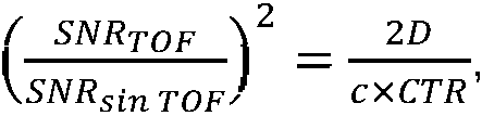
donde D es el diámetro del campo de visión (en inglés, "field of view”, o FOV) y c es la velocidad de la luz en el vacío (véase M. Conti, “Focus on Time-of-Flight PET: the benefits of improved time resolution”, Eur J. of Nuc. Med. Mol. Imaging, (2011) 38, 1147-1157). Esta ganancia en la variación de ruido está asociada con una ganancia similar (G) en la sensibilidad efectiva del escáner PET (véase M. Conti, B. Bendriem “The new opportunities for high time resolution clinical TOF PET”, Clinical and Translational Imaging (2019) 7:139-147), dada por la fórmula:where D is the diameter of the field of view (FOV) and c is the speed of light in vacuum (see M. Conti, “Focus on Time-of-Flight PET: the benefits of improved time resolution ", Eur J. of Nuc. Med. Mol. Imaging, (2011) 38, 1147-1157). This gain in noise variation is associated with a similar gain (G) in the effective sensitivity of the PET scanner (see M. Conti, B. Bendriem “The new opportunities for high time resolution clinical TOF PET”, Clinical and Translational Imaging (2019) 7: 139-147), given by the formula:

Una resolución de CTR de 100 ps mejoraría la sensibilidad efectiva del escáner de PET en un factor de aproximadamente 2, en comparación con el mejor escáner de PET de TOF en la actualidad (actualmente, Biograph Vision™ de Siemens, véase por ejemplo: https://usa.healthcare.siemens.com/molecular-imaging/pet-ct/biograph-vision), y en un factor de 18, en comparación con un escáner de PET sin capacidad de TOF. Si la CTR alcanza 10 ps, la ganancia de sensibilidad sería de 180, en comparación con un PET sin TOF, y más de 20, en comparación con Biograph Vision™, respectivamente.A CTR resolution of 100 ps would improve the effective sensitivity of the PET scanner by a factor of approximately 2, compared to the best TOF PET scanner available today (currently Biograph Vision ™ from Siemens, see for example: https: //usa.healthcare.siemens.com/molecular-imaging/pet-ct/biograph-vision), and by a factor of 18, compared to a PET scanner without TOF capability. If the CTR reaches 10 ps, the sensitivity gain would be 180, compared to a PET without TOF, and more than 20, compared to Biograph Vision ™, respectively.
Lograr una CTR de aproximadamente 10 ps de FWHM (anchura a media altura o, en inglés, "full width at half maximum”) permitiría obtener una representación en volumen tridimensional (3D) directa de la distribución de actividad estimada de un radiofármaco emisor de positrones, al nivel de mm y sin la necesidad de inversión tomográfica. Ello constituiría una mejora notable en la obtención de imágenes y cuantificación mediante PET. Además, una ganancia de dos órdenes de magnitud en la sensibilidad efectiva tendría las siguientes consecuencias para los escáneres PET:Achieving a CTR of approximately 10 ps of FWHM (full width at half maximum) would allow a direct three-dimensional (3D) volume representation of the estimated activity distribution of a positron-emitting radiopharmaceutical. , at the mm level and without the need for tomographic inversion. This would constitute a notable improvement in PET imaging and quantification. In addition, a gain of two orders of magnitude in effective sensitivity would have the following consequences for PET scanners:
- reducción de las dosis de radiación en procedimientos de obtención de imágenes moleculares hasta niveles despreciablemente bajos;- reduction of radiation doses in molecular imaging procedures to negligibly low levels;
- reducción de la cantidad sintetizada de radiofármaco necesario para cada examen y, por tanto, del coste relativamente alto asociado a los procedimientos de obtención de imágenes moleculares in vivo; - reduction of the synthesized amount of radiopharmaceutical required for each examination and, therefore, of the relatively high cost associated with in vivo molecular imaging procedures;
- extensión adicional del beneficio de los procedimientos de obtención de imágenes moleculares en otras áreas además de en oncología, por ejemplo en medicina de enfermedades cardiovasculares, neurológicas, inflamatorias, infecciosas o metabólicas (tales como diabetes), incluyendo en la medicina pediátrica, neonatal y prenatal;- further extension of the benefit of molecular imaging procedures in areas other than oncology, for example in medicine of cardiovascular, neurological, inflammatory, infectious or metabolic diseases (such as diabetes), including in pediatric, neonatal and medicine prenatal;
- maximizar la resolución espacial y temporal de la obtención de imágenes moleculares basada en PET; - maximize spatial and temporal resolution of PET-based molecular imaging;
- posibilidad de realizar estudios dinámicos precisos de procesos moleculares de alto interés en farmacología, para examinar y seleccionar moléculas candidatas para la siguiente generación de fármacos o nuevas aplicaciones de los mismos;- possibility of carrying out precise dynamic studies of molecular processes of high interest in pharmacology, to examine and select candidate molecules for the next generation of drugs or new applications thereof;
- posibilidad de ampliar la obtención de imágenes in vivo moleculares hacia el estudio de "biología de sistemas” del cuerpo humano, mediante sistemas de obtención de imágenes de todo el cuerpo;- possibility of expanding molecular in vivo imaging to the study of "systems biology" of the human body, using whole-body imaging systems;
- evitar la necesidad de cobertura angular completa del paciente en procedimientos de obtención de imágenes, abriendo muchas nuevas oportunidades para diseños de sistemas PET.- avoiding the need for complete angular coverage of the patient in imaging procedures, opening up many new opportunities for PET system designs.
Con el fin de mejorar la resolución temporal de escáneres PET TOF, recientemente se ha propuesto el concepto de "metacentelleadores” por uno de los inventores de esta solicitud de patente (véase R.M. Turtos, Paul Lecoq et al., “On the use of CdSe scintillating nanoplatelets as time taggers for high-energy gamma detection", npj 2D Mater Appl 3, 37 (2019) doi:10.1038/s41699-019-0120-8). Asimismo, como contribución novedosa respecto a la técnica anterior conocida, la presente invención propone un dispositivo para detectar rayos gamma que se basa en una combinación de metacentelleadores y "detectores de bloque” que mejoran la sensibilidad de un escáner PET, reduciendo el espacio muerto entre cristales, mediante una aproximación pixelada. Esta propuesta permite lograr una resolución de CTR de al menos 100 ps, pudiendo alcanzar incluso al menos 10 ps en un futuro próximo, en caso de combinarse con las mejoras previstas para los fotodetectores y su electrónica asociada en los próximos años.In order to improve the temporal resolution of PET TOF scanners, the concept of "meta-scintillators" has recently been proposed by one of the inventors of this patent application (see RM Turtos, Paul Lecoq et al., "On the use of CdSe scintillating nanoplatelets as time taggers for high-energy gamma detection ", npj 2D Mater Appl 3, 37 (2019) doi: 10.1038 / s41699-019-0120-8). Likewise, as a novel contribution with respect to the known prior art, the present invention proposes a device for detecting gamma rays that is based on a combination of meta-scintillators and "block detectors" that improve the sensitivity of a PET scanner, reducing the dead space between crystals, using a pixelated approximation. This proposal allows to achieve a CTR resolution of at least 100 ps, and may even reach at least 10 ps in the near future, if combined with the improvements planned for the photodetectors and their associated electronics in the next years.
DESCRIPCIÓN BREVE DE LA INVENCIÓNBRIEF DESCRIPTION OF THE INVENTION
A la vista de los problemas del estado de la técnica expuestos en la sección anterior, la presente invención propone un dispositivo de detección de rayos gamma de alta resolución que comprende preferentemente uno o más bloques de detección por metacentelleo, donde cada uno de dichos bloques de detección por metacentelleo comprenden una disposición alterna de capas de centelleo pesado y capas de material de centelleo ultrarrápido, que combinan de manera sinérgica el concepto de "metacentelleadores” y de "detectores de bloque” tal como se proponen de manera individual en la técnica anterior.In view of the problems of the state of the art exposed in the previous section, the present invention proposes a high-resolution gamma ray detection device that preferably comprises one or more meta-scintillation detection blocks, where each of said detection blocks Meta-scintillation detection comprises an alternating arrangement of heavy scintillation layers and ultra-fast scintillation material layers, synergistically combining the concept of "meta-scintillators" and "block detectors" as individually proposed in the prior art.
En el contexto de la invención, una capa de centelleo pesado es cualquier capa de material, o combinación de materiales, que tiene una densidad sustancialmente igual o superior a 5 g/cm3 (más preferentemente, entre 5 y 10 g/cm3), un número atómico efectivo sustancialmente igual o superior a 50, una producción de luz sustancialmente igual o superior a 10.000 fotones/MeV (más preferentemente, comprendida entre 10.000 y 100.000 fotones/MeV) y un tiempo de desintegración de centelleo sustancialmente igual o superior a 10 ns (y, más preferentemente, entre 10 y 1.000 ns).In the context of the invention, a heavy scintillation layer is any layer of material, or combination of materials, that has a density substantially equal to or greater than 5 g / cm3 (more preferably, between 5 and 10 g / cm3), a effective atomic number substantially equal to or greater than 50, a light output substantially equal to or greater than 10,000 photons / MeV (more preferably, between 10,000 and 100,000 photons / MeV) and a scintillation decay time substantially equal to or greater than 10 ns (and, more preferably, between 10 and 1,000 ns).
En una realización preferente de la invención, las capas de centelleo pesado comprenden materiales de centelleo BGO, LSO, LYSO, GSO, NaI, CsI, BaF2 , LuAP, LuAG y/o GGAG, solos o en combinación.In a preferred embodiment of the invention, the heavy scintillation layers comprise BGO, LSO, LYSO, GSO, NaI, CsI, BaF 2 , LuAP, LuAG and / or GGAG scintillation materials, alone or in combination.
En otra realización preferente de la invención, una o más de las capas de centelleo pesado tienen una densidad de entre 6 y 8 g/cm3, un número atómico efectivo superior a 60, una producción de luz comprendida entre 10.000 y 60.000 fotones/MeV y/o un tiempo de desintegración de centelleo de entre 10 y 100 ns.In another preferred embodiment of the invention, one or more of the heavy scintillation layers have a density between 6 and 8 g / cm3, an effective atomic number greater than 60, a light output between 10,000 and 60,000 photons / MeV and / or a scintillation decay time of between 10 and 100 ns.
En otra realización preferente de la invención, el grosor de las capas de centelleo pesado está comprendido entre 100 y 500 micrómetros.In another preferred embodiment of the invention, the thickness of the heavy scintillation layers is between 100 and 500 microns.
En otra realización preferente de la invención, el número total de capas de centelleo pesado en el bloque de detección por metacentelleo es de entre 50 y 150.In another preferred embodiment of the invention, the total number of heavy scintillation layers in the meta-scintillation detection block is between 50 and 150.
En el contexto de la invención, una capa de centelleo ultrarrápido es cualquier capa de material, o combinación de materiales, que tiene una tasa de producción de centelleo de al menos 100 fotones por 100 keV de energía depositados en menos de 1 ns.In the context of the invention, an ultrafast scintillation layer is any layer of material, or combination of materials, that has a scintillation production rate of at least 100 photons per 100 keV of energy deposited in less than 1 ns.
En una realización preferente de la invención, las capas de centelleo ultrarrápido poseen:In a preferred embodiment of the invention, the ultrafast scintillation layers have:
- una tasa de producción de centelleo de entre 100 y 5.000 fotones por 100 keV de energía depositados en menos de 1 ns; y/o- a scintillation production rate of between 100 and 5,000 photons per 100 keV of energy deposited in less than 1 ns; me
- una energía de producción de centelleo de hasta el 20% de la energía incidente de los rayos gamma que van a detectarse.- a scintillation production energy of up to 20% of the incident energy of the gamma rays to be detected.
En otra realización preferente de la invención, las capas de centelleo ultrarrápido tienen un grosor de entre 20 y 200 micrómetros.In another preferred embodiment of the invention, the flash scintillation layers have a thickness of between 20 and 200 microns.
En otra realización preferente de la invención, las capas de centelleo rápido comprenden centelleadores de plástico cargados con colorante, polímeros cargados con nanocristales, capas de nanocristales o estructuras de pozos cuánticos. In another preferred embodiment of the invention, the fast scintillation layers comprise dye-loaded plastic scintillators, nanocrystal-loaded polymers, nanocrystal layers, or quantum well structures.
En otra realización preferente de la invención, el bloque de detección por metacentelleo es cúbico o tiene la forma de un prisma rectangular, y dos o cuatro de sus caras opuestas están parcial o totalmente cubiertas por una disposición de fotodetectores.In another preferred embodiment of the invention, the meta-scintillation detection block is cubic or has the shape of a rectangular prism, and two or four of its opposite faces are partially or totally covered by an array of photodetectors.
En otra realización preferente de la invención, los fotodetectores tienen una característica de tiempo de respuesta para un único fotón (SPTR) de entre 10 y 100 ps.In another preferred embodiment of the invention, the photodetectors have a single photon response time (SPTR) characteristic of between 10 and 100 ps.
En otra realización preferente de la invención, cada fotodetector individual tiene una superficie de entre 1x1 mm2 y 6x6 mm2.In another preferred embodiment of the invention, each individual photodetector has a surface area of between 1x1mm2 and 6x6mm2.
En otra realización preferente de la invención, la disposición de fotodetectores comprende una yuxtaposición de fotodetectores individuales, líneas de fotodetectores empaquetados o matrices de fotodetectores.In another preferred embodiment of the invention, the photodetector array comprises a juxtaposition of individual photodetectors, lines of packed photodetectors, or arrays of photodetectors.
En otra realización preferente de la invención, dos de las caras opuestas del bloque de detección por metacentelleo están parcial o totalmente cubiertas por una disposición de fotodetectores y otras dos caras opuestas están cubiertas por un elemento reflector óptico para permitir la canalización de la luz en las capas de centelleo pesado y las capas de material de centelleo ultrarrápido, en la dirección de los fotodetectores.In another preferred embodiment of the invention, two of the opposite faces of the meta-scintillation detection block are partially or totally covered by an array of photodetectors and two other opposite faces are covered by an optical reflector element to allow channeling of light into the heavy scintillation layers and ultra-fast scintillation material layers, in the direction of the photodetectors.
En otra realización preferente de la invención, los planos de las capas de centelleo pesado y las capas de material de centelleo ultrarrápido están dispuestos sustancialmente ortogonales respecto a una dirección de incidencia principal de una fuente de rayos gamma.In another preferred embodiment of the invention, the planes of the heavy scintillation layers and the ultrafast scintillation material layers are arranged substantially orthogonal to a principal incidence direction of a gamma ray source.
En otra realización preferente de la invención, el dispositivo comprende una pluralidad de bloques de detección por metacentelleo paralelepípedos o en sección decreciente ensamblados en una geometría de anillo.In another preferred embodiment of the invention, the device comprises a plurality of tapered or parallelepiped meta-scintillation detection blocks assembled in a ring geometry.
En el contexto de la invención, la expresión “sustancialmente” se entenderá como igual a, o dentro de, un intervalo de variación de ±15%.In the context of the invention, the term "substantially" shall be understood as equal to, or within, a range of variation of ± 15%.
DESCRIPCIÓN DE LOS DIBUJOSDESCRIPTION OF THE DRAWINGS
Las características y ventajas anteriores y otras se entenderán más completamente a partir de la descripción detallada de la invención, así como a partir de las realizaciones preferentes haciendo referencia a las figuras adjuntas, que se describen en los siguientes párrafos, en las que: The above and other features and advantages will be more fully understood from the detailed description of the invention, as well as from the preferred embodiments with reference to the attached figures, which are described in the following paragraphs, in which:
Las figuras 1a-1b representan dos ejemplos (paralelepípedo y en sección decreciente, respectivamente) de un bloque de detección por metacentelleo, configurado como una disposición de capas alternas de centelleadores densos y ultrarrápidos, según una realización preferente la presente invención.Figures 1a-1b represent two examples (parallelepiped and tapered, respectively) of a meta-scintillation detection block, configured as an arrangement of alternating layers of dense and ultra-fast scintillators, according to a preferred embodiment of the present invention.
La figura 2 representa esquemáticamente la deposición de energía en los dos materiales de una heteroestructura de centelleador.Figure 2 schematically represents the energy deposition in the two materials of a scintillator heterostructure.
La figura 3 muestra un bloque de detección por metacentelleo cubierto por una disposición de fotodetectores sobre sus cuatro caras laterales, según una realización preferente la presente invención.Figure 3 shows a meta-scintillation detection block covered by an array of photodetectors on its four side faces, according to a preferred embodiment of the present invention.
La figura 4 ilustra el principio de determinación de la posición en las direcciones X, Y y Z, en un bloque de detección por metacentelleo cubierto por cuatro caras laterales de matrices de fotodetectores, según una realización preferente la presente invención.Figure 4 illustrates the principle of determining the position in the X, Y and Z directions, in a detection block by meta-scintillation covered by four lateral faces of photodetector arrays, according to a preferred embodiment of the present invention.
La figura 5 ilustra el principio de determinación de la posición en las direcciones X, Y y Z, en un bloque de detección por metacentelleo cubierto por dos caras laterales de matrices de fotodetectores, según una realización preferente la presente invención.Figure 5 illustrates the principle of determining the position in the X, Y and Z directions, in a detection block by meta-scintillation covered by two lateral faces of photodetector arrays, according to a preferred embodiment of the present invention.
- Referencias numéricas usadas en los dibujos:- Numerical references used in the drawings:

DESCRIPCIÓN DETALLADA DE LA INVENCIÓNDETAILED DESCRIPTION OF THE INVENTION
A continuación se expone una descripción detallada de la invención relacionada con diferentes realizaciones preferentes de la misma, basándose en las figuras 1-5 de este documento. Dicha descripción se proporciona con fines ilustrativos, pero no limitativos, de la invención reivindicada. The following is a detailed description of the invention related to different preferred embodiments thereof, based on Figures 1-5 of this document. Said description is provided for illustrative, but not limiting, purposes of the claimed invention.
En una realización preferente de la presente invención (figuras 1a-1b), un bloque de detección (1) por metacentelleo de rayos gamma se configura como una disposición alterna de capas (2) de centelleo pesado y capas (3) de material de centelleo ultrarrápido (según lo descrito en la descripción breve de la invención), cuyos planos están, preferentemente, dispuestos de forma sustancialmente ortogonal respecto a una dirección de incidencia principal de los rayos gamma. La disposición de capas (2) de centelleo pesado y capas (3) de material de centelleo ultrarrápido alternas en un bloque de detección (1) por metacentelleo, en un dispositivo según la invención, también se designará como “heteroestructura”.In a preferred embodiment of the present invention (Figures 1a-1b), a gamma ray meta-scintillation detection block (1) is configured as an alternating arrangement of layers (2) of heavy scintillation and layers (3) of scintillation material. ultrafast (as described in the brief description of the invention), the planes of which are preferably arranged substantially orthogonal to a principal incidence direction of the gamma rays. The arrangement of alternating layers (2) of heavy scintillation and layers (3) of ultra-fast scintillation material in a meta-scintillation detection block (1), in a device according to the invention, will also be referred to as "heterostructure".
En diferentes realizaciones de la invención, la forma del bloque de detección (1) por metacentelleo de rayos gamma puede ser paralelepípeda (figura 1a) o en sección decreciente (figura 1b), para permitir el ensamblaje de varios detectores (1) de bloque de metacentelleador en una geometría de anillo.In different embodiments of the invention, the shape of the gamma ray meta-scintillation detection block (1) can be parallelepiped (figure 1a) or tapered (figure 1b), to allow the assembly of several detectors (1) of the gamma ray block meta-scintillator in a ring geometry.
Las capas (2) de centelleo pesado pueden fabricarse con materiales de centelleo habitualmente usados en detectores gamma, tales como BGO, LSO, LYSO, GSO, NaI, CsI, BaF2 , LuAP, LuAG, GGAG, etc. Sin embargo, para los fines de la invención, también puede usarse como material de las capas (2) de centelleo pesado cualquier material o combinación de materiales que tengan una densidad, número atómico, producción de luz y/o tiempos de emisión como para permitir una buena eficiencia de detección de rayos gamma/cm, buena resolución de energía y/o determinación espacial del punto de interacción gamma dentro del material, y tasas de adquisición de datos compatibles con aplicaciones de detección de rayos gamma habituales (hasta unos pocos MHz). Por ejemplo, en el caso de un escáner PET, la mayor parte de los cristales indicados tienen una densidad de entre 6 y 8 g/cm3, un número atómico efectivo (EAN) superior a 60, una producción de luz comprendida entre 10.000 y 60.000 fotones/MeV y un tiempo de desintegración de centelleo en el intervalo de decenas a cientos de ns.The heavy scintillation layers (2) can be made with scintillation materials commonly used in gamma detectors, such as BGO, LSO, LYSO, GSO, NaI, CsI, BaF 2 , LuAP, LuAG, GGAG, etc. However, for the purposes of the invention, any material or combination of materials having a density, atomic number, light production and / or emission times may also be used as the material of the heavy scintillation layers (2) to allow good gamma ray detection efficiency / cm, good energy resolution and / or spatial determination of the gamma interaction point within the material, and data acquisition rates compatible with common gamma ray detection applications (up to a few MHz) . For example, in the case of a PET scanner, most of the indicated crystals have a density between 6 and 8 g / cm3, an effective atomic number (EAN) greater than 60, a light output between 10,000 and 60,000 photons / MeV and a scintillation decay time in the range of tens to hundreds of ns.
El grosor de las capas (2) de centelleo pesado se determina mediante el intervalo del electrón de retroceso a partir de un evento de conversión de rayos gamma fotoeléctricos, que es normalmente del orden de 100 a 300 micrómetros en los materiales preferentes, para una energía gamma de 511 keV.The thickness of the heavy scintillation layers (2) is determined by the range of the recoil electron from a photoelectric gamma ray conversion event, which is typically on the order of 100 to 300 microns in preferred materials, for an energy gamma of 511 keV.
El número total de tales capas (2) de centelleo pesado en el dispositivo de la invención se determina mediante la eficiencia de detección de rayos gamma deseada para el bloque de detección (1) por metacentelleo. Por ejemplo, los escáneres PET habituales usan longitudes de cristal pesado que oscilan entre 10 mm y 30 mm, lo cual corresponde a entre 50 y 150 capas (2) de 200 micrómetros de grosor.The total number of such heavy scintillation layers (2) in the device of the invention is determined by the desired gamma ray detection efficiency for the meta-scintillation detection block (1). For example, common PET scanners use lengths of heavy glass ranging between 10 mm and 30 mm, which corresponds to between 50 and 150 layers (2) of 200 micrometers thick.
Por otro lado, las capas (3) de centelleo ultrarrápido del bloque de detección (1) por metacentelleo están diseñadas para analizar, a modo de sonda, los electrones de retroceso fotoeléctricos, de tal manera que se produce normalmente un grupo de entre varios cientos hasta algunos miles de fotones, para una deposición de energía inicial de aproximadamente 100 keV. El motivo para limitar la deposición de energía en este material, preferentemente hasta el 20% de la energía gamma inicial, es limitar el impacto de las fluctuaciones de muestreo sobre la resolución de energía de la disposición, para el caso en el que la producción de luz intrínseca de los dos materiales sea diferente. Un grosor indicativo para estas capas de centelleo rápido puede oscilar entre 20 micrómetros y 200 micrómetros, dependiendo de la producción de luz intrínseca del material elegido.On the other hand, the ultra-fast scintillation layers (3) of the meta-scintillation detection block (1) are designed to probe, like a probe, the photoelectric recoil electrons, in such a way that a group of between several hundred is normally produced. up to a few thousand photons, for an initial energy deposition of approximately 100 keV. The reason for limiting the energy deposition in this material, preferably up to 20% of the initial gamma energy, is to limit the impact of the sampling fluctuations on the energy resolution of the arrangement, for the case where the production of intrinsic light of the two materials is different. An indicative thickness for these fast scintillation layers can range from 20 microns to 200 microns, depending on the intrinsic light output of the chosen material.
En diferentes realizaciones de la invención, las capas (3) de centelleo rápido pueden fabricarse de centelleadores de plástico (cargados con colorante), polímero cargado con nanocristales, capas delgadas de nanocristales o múltiples estructuras de pozos cuánticos, o cualquier otro material con un centelleo rápido que permita la producción de al menos varios cientos de fotones por 100 keV de energía depositados en menos de 1 ns.In different embodiments of the invention, the fast scintillation layers (3) can be made of plastic scintillators (loaded with dye), polymer loaded with nanocrystals, thin layers of nanocrystals or multiple quantum well structures, or any other material with a scintillation fast that allows the production of at least several hundred photons per 100 keV of energy deposited in less than 1 ns.
Con el fin de permitir compartir la energía del electrón de retroceso en ambos materiales de la heteroestructura de capas (2) de centelleador y capas (3) de centelleador formada en el bloque de detección (1) por metacentelleo de la invención, el grosor de las capas (2) de centelleo pesado es, preferentemente, del orden de 200 micrómetros, dependiendo su valor exacto de las características del material de centelleo pesado elegido. La figura 2 representa una representación esquemática de la deposición de energía en las capas (2, 3) que forman la heteroestructura.In order to allow sharing the energy of the recoil electron in both materials of the heterostructure of scintillator layers (2) and scintillator layers (3) formed in the detection block (1) by meta-scintillation of the invention, the thickness of The heavy scintillation layers (2) is preferably of the order of 200 microns, their exact value depending on the characteristics of the chosen heavy scintillation material. Figure 2 represents a schematic representation of the energy deposition in the layers (2, 3) that form the heterostructure.
En una realización adicional de la invención, el bloque de detección (1) por metacentelleo es cúbico o tiene la forma de un prisma rectangular y cuatro de sus caras están preferentemente cubiertas por una disposición de fotodetectores (4) (véase la figura 3). Estos fotodetectores (4) comprenden preferentemente fotomultiplicadores de silicio (SiPM), pero pueden ser de cualquier tipo, siempre que tengan una característica de tiempo de respuesta compatible con el objetivo de resolución temporal en coincidencia (CTR) de 10 a 100 ps. El área de cada fotodetector (4) individual oscilará normalmente entre 1x1 mm2 y 6x6 mm2, dependiendo de los objetivos de prestaciones de resolución espacial y temporal del bloque de detección (1) por metacentelleo. Esta disposición de fotodetectores (4) puede estar compuesta por una yuxtaposición de fotodetectores (4) individuales, por líneas de fotodetectores (4) empaquetados o por matrices de fotodetectores (4).In a further embodiment of the invention, the meta-scintillation detection block (1) is cubic or has the shape of a rectangular prism and four of its faces are preferably covered by an array of photodetectors (4) (see Figure 3). These photodetectors (4) preferably comprise silicon photomultipliers (SiPM), but they can be of any type, as long as they have a response time characteristic compatible with the coincident temporal resolution objective (CTR) of 10 to 100 ps. The area of each individual photodetector (4) will typically range from 1x1mm2 to 6x6mm2, depending on the spatial and temporal resolution performance objectives of the meta-scintillation detection block (1). This arrangement of photodetectors (4) can be composed of a juxtaposition of individual photodetectors (4), by lines of packed photodetectors (4) or by arrays of photodetectors (4).
Tal como se representa en la figura 4, la posición de la interacción de rayos gamma se determinará en cuanto a la profundidad (dirección Z) mediante la identificación de la capa de centelleo (o grupo de capas) que emite luz con una precisión definida por la granularidad de la disposición de fotodetectores (4) en Z, X e Y, por la compartición de luz y distribución en el tiempo de las señales recibidas por los fotodetectores (4) orientados hacia las capas (2, 3) de emisión de luz, en lados opuestos del bloque de detección (1) por metacentelleo. Puede calcularse que la superficie total de fotodetectores (4) necesaria en esta configuración es similar a la de la lectura de un PET comercial en la parte posterior de los cristales, si el bloque de detección (1) por metacentelleo tiene dimensiones laterales iguales a 4 veces su grosor.As depicted in Figure 4, the position of the gamma ray interaction will be determined in depth (Z direction) by identifying the scintillation layer (or group of layers) that emits light with a precision defined by the granularity of the arrangement of photodetectors (4) in Z, X and Y, due to the sharing of light and distribution in time of the signals received by the photodetectors (4) oriented towards the light emission layers (2, 3) , on opposite sides of the detection block (1) by meta-scintillation. It can be calculated that the total surface of photodetectors (4) needed in this configuration is similar to that of the reading of a commercial PET on the back of the crystals, if the detection block (1) by meta-scintillation has lateral dimensions equal to 4 times its thickness.
Además, considerando que los cristales de centelleo en PET comercial están dispuestos habitualmente en una distribución de píxeles con una sección de aproximadamente 3x3 mm2, separados al menos 100 micrómetros, y que pueden fabricarse fotodetectores de SiPM de tan sólo 1 mm, el espacio muerto total en ambas configuraciones es equivalente si el bloque de detección (1) por metacentelleo tiene una sección de al menos 6x6 cm2.Furthermore, considering that commercial PET scintillation crystals are usually arranged in a pixel distribution with a section of approximately 3x3 mm2, separated by at least 100 micrometers, and that SiPM photodetectors of as little as 1 mm can be manufactured, the total dead space in both configurations it is equivalent if the meta-scintillation detection block (1) has a section of at least 6x6 cm2.
En una tercera realización de la invención, la lectura del dispositivo puede proporcionarse sobre dos caras opuestas del bloque de detección (1) por metacentelleo, en vez de cuatro (para un bloque (1) paralelepípedo o prismático), reduciendo así el número total y el coste de los fotodetectores (4) en un factor de 2 y permitiendo el ensamblaje de anillos de PET esencialmente sin ningún espacio muerto (tal como se observa en la figura 5). En este caso, las dos caras laterales del bloque de detección (1) por metacentelleo que no se leen por los fotodetectores (4) estarán preferentemente cubiertas por un elemento (5) reflector óptico para permitir una fácil canalización de la luz en las capas (2, 3) de centelleo, en la dirección de los fotodetectores (4).In a third embodiment of the invention, the reading of the device can be provided on two opposite faces of the detection block (1) by meta-scintillation, instead of four (for a parallelepiped or prismatic block (1)), thus reducing the total number and the cost of the photodetectors (4) by a factor of 2 and allowing the assembly of PET rings with essentially no dead space (as seen in Figure 5). In this case, the two lateral faces of the detection block (1) by meta-scintillation that are not read by the photodetectors (4) will preferably be covered by an optical reflector element (5) to allow easy channeling of light in the layers ( 2, 3) scintillation, in the direction of the photodetectors (4).
En una cuarta realización de la invención, cada una de las capas de centelleo ((2) densa y/o (3) rápida) puede segmentarse para restringir el número de fotodetectores (4) que recogen la luz en ambos extremos del bloque de detección (1) por metacentelleo. Esta posibilidad proporciona flexibilidad para la optimización de la resolución espacial y temporal de la heteroestructura, en función de las capas (2, 3) de centelleador y del material de fotodetector (4) y las características geométricas. Esta realización también puede tener un impacto positivo sobre el coste de producción de las capas (2, 3). In a fourth embodiment of the invention, each of the scintillation layers ((2) dense and / or (3) fast) can be segmented to restrict the number of photodetectors (4) that collect light at both ends of the detection block. (1) by meta-blink. This possibility provides flexibility for optimizing the spatial and temporal resolution of the heterostructure, as a function of the scintillator layers (2, 3) and the photodetector material (4) and the geometric characteristics. This embodiment can also have a positive impact on the cost of production of the layers (2, 3).
Claims (15)


Priority Applications (4)
| Application Number | Priority Date | Filing Date | Title |
|---|---|---|---|
| ES202030081A ES2847577A1 (en) | 2020-02-03 | 2020-02-03 | DEVICE FOR DETECTION OF GAMMA RAYS BASED ON BLOCKS OF METACENTELLEO DETECTION (Machine-translation by Google Translate, not legally binding) |
| PCT/EP2021/052429 WO2021156250A1 (en) | 2020-02-03 | 2021-02-02 | Device for the detection of gamma rays based on metascintillator block detectors |
| EP21703237.4A EP4100766A1 (en) | 2020-02-03 | 2021-02-02 | Device for the detection of gamma rays based on metascintillator block detectors |
| US17/797,011 US20230075571A1 (en) | 2020-02-03 | 2021-02-02 | Device for the detection of gamma rays based on metascintillator block detectors |
Applications Claiming Priority (1)
| Application Number | Priority Date | Filing Date | Title |
|---|---|---|---|
| ES202030081A ES2847577A1 (en) | 2020-02-03 | 2020-02-03 | DEVICE FOR DETECTION OF GAMMA RAYS BASED ON BLOCKS OF METACENTELLEO DETECTION (Machine-translation by Google Translate, not legally binding) |
Publications (1)
| Publication Number | Publication Date |
|---|---|
| ES2847577A1 true ES2847577A1 (en) | 2021-08-03 |
Family
ID=74550660
Family Applications (1)
| Application Number | Title | Priority Date | Filing Date |
|---|---|---|---|
| ES202030081A Withdrawn ES2847577A1 (en) | 2020-02-03 | 2020-02-03 | DEVICE FOR DETECTION OF GAMMA RAYS BASED ON BLOCKS OF METACENTELLEO DETECTION (Machine-translation by Google Translate, not legally binding) |
Country Status (4)
| Country | Link |
|---|---|
| US (1) | US20230075571A1 (en) |
| EP (1) | EP4100766A1 (en) |
| ES (1) | ES2847577A1 (en) |
| WO (1) | WO2021156250A1 (en) |
Families Citing this family (2)
| Publication number | Priority date | Publication date | Assignee | Title |
|---|---|---|---|---|
| GB202101278D0 (en) * | 2021-01-29 | 2021-03-17 | Serac Imaging Systems Ltd | Imaging device |
| CN118800639B (en) * | 2024-07-10 | 2025-10-17 | 西北核技术研究所 | MeV-level gamma sensitive electron multiplier and preparation method thereof |
Citations (4)
| Publication number | Priority date | Publication date | Assignee | Title |
|---|---|---|---|---|
| WO2015028605A1 (en) * | 2013-08-30 | 2015-03-05 | Uniwersytet Jagiellonski | A detecting device for determining a position of reaction of gamma quanta and a method for determining a position of reaction of a gamma quanta in positron emission tomography |
| US20150177386A1 (en) * | 2013-12-20 | 2015-06-25 | Koninklijke Philips N.V. | Temperature stability for a digital positron emission tomography (pet) detector |
| US20150331115A1 (en) * | 2012-05-31 | 2015-11-19 | Minnesota Imaging And Engineering | Detector systems for radiation imaging |
| EP3018496A1 (en) * | 2014-11-06 | 2016-05-11 | General Equipment for Medical Imaging S.A. (Oncovision) | Hybrid scintillation module |
Family Cites Families (3)
| Publication number | Priority date | Publication date | Assignee | Title |
|---|---|---|---|---|
| US9709684B2 (en) * | 2014-12-15 | 2017-07-18 | General Electric Company | Systems and methods for scintillators having micro-crack surfaces |
| WO2019036865A1 (en) * | 2017-08-21 | 2019-02-28 | Shenzhen United Imaging Healthcare Co., Ltd. | Method and apparatus for positron emission tomography |
| US10191160B1 (en) * | 2018-08-31 | 2019-01-29 | David Edward Newman | Staggered detector array for locating radioactive sources |
-
2020
- 2020-02-03 ES ES202030081A patent/ES2847577A1/en not_active Withdrawn
-
2021
- 2021-02-02 US US17/797,011 patent/US20230075571A1/en not_active Abandoned
- 2021-02-02 EP EP21703237.4A patent/EP4100766A1/en not_active Withdrawn
- 2021-02-02 WO PCT/EP2021/052429 patent/WO2021156250A1/en not_active Ceased
Patent Citations (4)
| Publication number | Priority date | Publication date | Assignee | Title |
|---|---|---|---|---|
| US20150331115A1 (en) * | 2012-05-31 | 2015-11-19 | Minnesota Imaging And Engineering | Detector systems for radiation imaging |
| WO2015028605A1 (en) * | 2013-08-30 | 2015-03-05 | Uniwersytet Jagiellonski | A detecting device for determining a position of reaction of gamma quanta and a method for determining a position of reaction of a gamma quanta in positron emission tomography |
| US20150177386A1 (en) * | 2013-12-20 | 2015-06-25 | Koninklijke Philips N.V. | Temperature stability for a digital positron emission tomography (pet) detector |
| EP3018496A1 (en) * | 2014-11-06 | 2016-05-11 | General Equipment for Medical Imaging S.A. (Oncovision) | Hybrid scintillation module |
Non-Patent Citations (1)
| Title |
|---|
| TURTOS, R.M., GUNDACKER, S., OMELKOV, S. ET AL. . On the use of CdSe scintillating nanoplatelets as time taggers for high-energy gamma detection. npj 2D Mater Appl, 04/10/2019, Vol. 3, Páginas 1-10 [en línea][recuperado el 13/05/2020]. (DOI: doi.org/10.1038/s41699-019-0120-8) figura 3a * |
Also Published As
| Publication number | Publication date |
|---|---|
| WO2021156250A1 (en) | 2021-08-12 |
| EP4100766A1 (en) | 2022-12-14 |
| US20230075571A1 (en) | 2023-03-09 |
Similar Documents
| Publication | Publication Date | Title |
|---|---|---|
| US10955569B2 (en) | Detector systems for integrated radiation imaging | |
| Zatcepin et al. | Detectors in positron emission tomography | |
| US9335425B2 (en) | Modelling of ToF-DOI detector arrays | |
| Kuhn et al. | Design of a lanthanum bromide detector for time-of-flight PET | |
| Peng et al. | Recent developments in PET instrumentation | |
| Hutton et al. | Advances in clinical molecular imaging instrumentation | |
| Yamamoto et al. | Development of a Si-PM-based high-resolution PET system for small animals | |
| ES2527827T3 (en) | Strips device and procedure for determining the location and reaction time of the gamma quanta and the use of the device to determine the location and reaction time of the gamma quanta in positron emission tomography | |
| CN105592795B (en) | Multimodal Imaging Device | |
| Doshi et al. | maxPET, a dedicated mammary and axillary region PET imaging system for breast cancer | |
| US8946643B2 (en) | Virtual pixelated detector for pet and/or spect | |
| ES2757984B2 (en) | DEVICE FOR THE DETECTION OF GAMMA RAYS WITH ACTIVE SEALS | |
| US20140246594A1 (en) | Gamma detector based on geigermode avalanche photodiodes | |
| ES2847577A1 (en) | DEVICE FOR DETECTION OF GAMMA RAYS BASED ON BLOCKS OF METACENTELLEO DETECTION (Machine-translation by Google Translate, not legally binding) | |
| Yamamoto et al. | Development of a high-resolution Si-PM-based gamma camera system | |
| Eriksson et al. | Experience with scintillators for PET: towards the fifth generation of PET scanners | |
| Lu et al. | Development of a SiPM-based PET imaging system for small animals | |
| WO2016112135A1 (en) | Compact trapezoidal pet detector with light sharing | |
| JP7022125B2 (en) | Optical sensor signal processing method | |
| Pizzichemi | Positron Emission Tomography: State of the art and future developments | |
| Surti et al. | Current status of PET technology | |
| Kato et al. | High resolution phoswich gamma-ray imager utilizing monolithic MPPC arrays with submillimeter pixelized crystals | |
| Moehrs et al. | A small-animal PET design using SiPMs and Anger logic with intrinsic DOI | |
| Ye et al. | Experimental studies of the decoding performances of a semi-monolithic scintillator detector | |
| Raptis et al. | Validation of LYSO scintillators coupled to SensL C-series SiPM's detectors |
Legal Events
| Date | Code | Title | Description |
|---|---|---|---|
| BA2A | Patent application published |
Ref document number: 2847577 Country of ref document: ES Kind code of ref document: A1 Effective date: 20210803 |
|
| FA2A | Application withdrawn |
Effective date: 20211118 |