ES2856688T3 - Medical tubes and manufacturing procedures - Google Patents
Medical tubes and manufacturing procedures Download PDFInfo
- Publication number
- ES2856688T3 ES2856688T3 ES13859885T ES13859885T ES2856688T3 ES 2856688 T3 ES2856688 T3 ES 2856688T3 ES 13859885 T ES13859885 T ES 13859885T ES 13859885 T ES13859885 T ES 13859885T ES 2856688 T3 ES2856688 T3 ES 2856688T3
- Authority
- ES
- Spain
- Prior art keywords
- tube
- elongated member
- lumen
- elongated
- wall
- Prior art date
- Legal status (The legal status is an assumption and is not a legal conclusion. Google has not performed a legal analysis and makes no representation as to the accuracy of the status listed.)
- Active
Links
Classifications
-
- A—HUMAN NECESSITIES
- A61—MEDICAL OR VETERINARY SCIENCE; HYGIENE
- A61M—DEVICES FOR INTRODUCING MEDIA INTO, OR ONTO, THE BODY; DEVICES FOR TRANSDUCING BODY MEDIA OR FOR TAKING MEDIA FROM THE BODY; DEVICES FOR PRODUCING OR ENDING SLEEP OR STUPOR
- A61M16/00—Devices for influencing the respiratory system of patients by gas treatment, e.g. ventilators; Tracheal tubes
- A61M16/08—Bellows; Connecting tubes ; Water traps; Patient circuits
- A61M16/0875—Connecting tubes
-
- A—HUMAN NECESSITIES
- A61—MEDICAL OR VETERINARY SCIENCE; HYGIENE
- A61M—DEVICES FOR INTRODUCING MEDIA INTO, OR ONTO, THE BODY; DEVICES FOR TRANSDUCING BODY MEDIA OR FOR TAKING MEDIA FROM THE BODY; DEVICES FOR PRODUCING OR ENDING SLEEP OR STUPOR
- A61M39/00—Tubes, tube connectors, tube couplings, valves, access sites or the like, specially adapted for medical use
- A61M39/08—Tubes; Storage means specially adapted therefor
-
- A—HUMAN NECESSITIES
- A61—MEDICAL OR VETERINARY SCIENCE; HYGIENE
- A61M—DEVICES FOR INTRODUCING MEDIA INTO, OR ONTO, THE BODY; DEVICES FOR TRANSDUCING BODY MEDIA OR FOR TAKING MEDIA FROM THE BODY; DEVICES FOR PRODUCING OR ENDING SLEEP OR STUPOR
- A61M16/00—Devices for influencing the respiratory system of patients by gas treatment, e.g. ventilators; Tracheal tubes
- A61M16/0057—Pumps therefor
- A61M16/0066—Blowers or centrifugal pumps
-
- A—HUMAN NECESSITIES
- A61—MEDICAL OR VETERINARY SCIENCE; HYGIENE
- A61M—DEVICES FOR INTRODUCING MEDIA INTO, OR ONTO, THE BODY; DEVICES FOR TRANSDUCING BODY MEDIA OR FOR TAKING MEDIA FROM THE BODY; DEVICES FOR PRODUCING OR ENDING SLEEP OR STUPOR
- A61M16/00—Devices for influencing the respiratory system of patients by gas treatment, e.g. ventilators; Tracheal tubes
- A61M16/06—Respiratory or anaesthetic masks
- A61M16/0666—Nasal cannulas or tubing
-
- A—HUMAN NECESSITIES
- A61—MEDICAL OR VETERINARY SCIENCE; HYGIENE
- A61M—DEVICES FOR INTRODUCING MEDIA INTO, OR ONTO, THE BODY; DEVICES FOR TRANSDUCING BODY MEDIA OR FOR TAKING MEDIA FROM THE BODY; DEVICES FOR PRODUCING OR ENDING SLEEP OR STUPOR
- A61M16/00—Devices for influencing the respiratory system of patients by gas treatment, e.g. ventilators; Tracheal tubes
- A61M16/06—Respiratory or anaesthetic masks
- A61M16/0683—Holding devices therefor
-
- A—HUMAN NECESSITIES
- A61—MEDICAL OR VETERINARY SCIENCE; HYGIENE
- A61M—DEVICES FOR INTRODUCING MEDIA INTO, OR ONTO, THE BODY; DEVICES FOR TRANSDUCING BODY MEDIA OR FOR TAKING MEDIA FROM THE BODY; DEVICES FOR PRODUCING OR ENDING SLEEP OR STUPOR
- A61M16/00—Devices for influencing the respiratory system of patients by gas treatment, e.g. ventilators; Tracheal tubes
- A61M16/08—Bellows; Connecting tubes ; Water traps; Patient circuits
- A61M16/0816—Joints or connectors
-
- A—HUMAN NECESSITIES
- A61—MEDICAL OR VETERINARY SCIENCE; HYGIENE
- A61M—DEVICES FOR INTRODUCING MEDIA INTO, OR ONTO, THE BODY; DEVICES FOR TRANSDUCING BODY MEDIA OR FOR TAKING MEDIA FROM THE BODY; DEVICES FOR PRODUCING OR ENDING SLEEP OR STUPOR
- A61M16/00—Devices for influencing the respiratory system of patients by gas treatment, e.g. ventilators; Tracheal tubes
- A61M16/10—Preparation of respiratory gases or vapours
- A61M16/1075—Preparation of respiratory gases or vapours by influencing the temperature
- A61M16/1095—Preparation of respiratory gases or vapours by influencing the temperature in the connecting tubes
-
- A—HUMAN NECESSITIES
- A61—MEDICAL OR VETERINARY SCIENCE; HYGIENE
- A61M—DEVICES FOR INTRODUCING MEDIA INTO, OR ONTO, THE BODY; DEVICES FOR TRANSDUCING BODY MEDIA OR FOR TAKING MEDIA FROM THE BODY; DEVICES FOR PRODUCING OR ENDING SLEEP OR STUPOR
- A61M16/00—Devices for influencing the respiratory system of patients by gas treatment, e.g. ventilators; Tracheal tubes
- A61M16/10—Preparation of respiratory gases or vapours
- A61M16/14—Preparation of respiratory gases or vapours by mixing different fluids, one of them being in a liquid phase
- A61M16/16—Devices to humidify the respiration air
-
- A—HUMAN NECESSITIES
- A61—MEDICAL OR VETERINARY SCIENCE; HYGIENE
- A61M—DEVICES FOR INTRODUCING MEDIA INTO, OR ONTO, THE BODY; DEVICES FOR TRANSDUCING BODY MEDIA OR FOR TAKING MEDIA FROM THE BODY; DEVICES FOR PRODUCING OR ENDING SLEEP OR STUPOR
- A61M39/00—Tubes, tube connectors, tube couplings, valves, access sites or the like, specially adapted for medical use
- A61M39/10—Tube connectors; Tube couplings
- A61M2039/1022—Tube connectors; Tube couplings additionally providing electrical connection
-
- A—HUMAN NECESSITIES
- A61—MEDICAL OR VETERINARY SCIENCE; HYGIENE
- A61M—DEVICES FOR INTRODUCING MEDIA INTO, OR ONTO, THE BODY; DEVICES FOR TRANSDUCING BODY MEDIA OR FOR TAKING MEDIA FROM THE BODY; DEVICES FOR PRODUCING OR ENDING SLEEP OR STUPOR
- A61M2205/00—General characteristics of the apparatus
- A61M2205/33—Controlling, regulating or measuring
- A61M2205/3368—Temperature
- A61M2205/3372—Temperature compensation
-
- A—HUMAN NECESSITIES
- A61—MEDICAL OR VETERINARY SCIENCE; HYGIENE
- A61M—DEVICES FOR INTRODUCING MEDIA INTO, OR ONTO, THE BODY; DEVICES FOR TRANSDUCING BODY MEDIA OR FOR TAKING MEDIA FROM THE BODY; DEVICES FOR PRODUCING OR ENDING SLEEP OR STUPOR
- A61M2207/00—Methods of manufacture, assembly or production
-
- B—PERFORMING OPERATIONS; TRANSPORTING
- B29—WORKING OF PLASTICS; WORKING OF SUBSTANCES IN A PLASTIC STATE IN GENERAL
- B29C—SHAPING OR JOINING OF PLASTICS; SHAPING OF MATERIAL IN A PLASTIC STATE, NOT OTHERWISE PROVIDED FOR; AFTER-TREATMENT OF THE SHAPED PRODUCTS, e.g. REPAIRING
- B29C53/00—Shaping by bending, folding, twisting, straightening or flattening; Apparatus therefor
- B29C53/56—Winding and joining, e.g. winding spirally
- B29C53/58—Winding and joining, e.g. winding spirally helically
- B29C53/78—Winding and joining, e.g. winding spirally helically using profiled sheets or strips
- B29C53/785—Winding and joining, e.g. winding spirally helically using profiled sheets or strips with reinforcements
Landscapes
- Health & Medical Sciences (AREA)
- Heart & Thoracic Surgery (AREA)
- Public Health (AREA)
- Veterinary Medicine (AREA)
- Anesthesiology (AREA)
- Biomedical Technology (AREA)
- Hematology (AREA)
- Life Sciences & Earth Sciences (AREA)
- Animal Behavior & Ethology (AREA)
- General Health & Medical Sciences (AREA)
- Pulmonology (AREA)
- Engineering & Computer Science (AREA)
- Emergency Medicine (AREA)
- Media Introduction/Drainage Providing Device (AREA)
- External Artificial Organs (AREA)
- Rigid Pipes And Flexible Pipes (AREA)
- Materials For Medical Uses (AREA)
- Infusion, Injection, And Reservoir Apparatuses (AREA)
- Otolaryngology (AREA)
- Medical Preparation Storing Or Oral Administration Devices (AREA)
Abstract
Un tubo de respiración para uso en circuitos médicos para proporcionar gases a y/o extraer gases de un paciente, el tubo de respiración comprende: un primer miembro alargado (203) que comprende un cuerpo hueco enrollado en espiral para formar, al menos en parte, un tubo alargado que tiene un eje longitudinal, un lumen (207) que se extiende a lo largo del eje longitudinal, y una pared hueca que rodea el lumen (207), teniendo la pared una porción interior próxima al lumen y una porción exterior que se aleja del lumen, un segundo miembro alargado (205) enrollado en espiral y unido entre las vueltas adyacentes del primer miembro alargado (203), formando el segundo miembro alargado (205) al menos una porción del lumen (207) del tubo alargado, caracterizado porque: la porción interior de la pared tiene un espesor menor que la porción exterior de la pared, el espesor de la porción exterior de la pared está en el intervalo de aproximadamente 0,14 mm y aproximadamente 0,44 mm, y el espesor de la porción interna de la pared está en el intervalo de aproximadamente 0,05 mm y aproximadamente 0,30 mm.A breathing tube for use in medical circuits to provide gases to and / or extract gases from a patient, the breathing tube comprises: a first elongated member (203) comprising a hollow body spirally wound to form, at least in part, an elongated tube having a longitudinal axis, a lumen (207) extending along the longitudinal axis, and a hollow wall surrounding the lumen (207), the wall having an interior portion near the lumen and an exterior portion that moving away from the lumen, a second elongated member (205) coiled in a spiral and joined between adjacent turns of the first elongated member (203), the second elongated member (205) forming at least a portion of the lumen (207) of the elongated tube, characterized in that: the inner portion of the wall has a thickness less than the outer portion of the wall, the thickness of the outer portion of the wall is in the range of about 0.14mm and about 0.44mm, and the thickness of the The inner portion of the wall is in the range of about 0.05mm and about 0.30mm.
Description
DESCRIPCIÓNDESCRIPTION
Tubos médicos y procedimientos de fabricaciónMedical tubes and manufacturing procedures
La presente solicitud reivindica el beneficio de prioridad, según el 35 U.S.C. § 119(e), de la Solicitud Provisoria de los Estados Unidos Núm. 61/733.359, titulada TUBOS MÉDICOS Y PROCEDIMIENTOS DE FABRICACIÓN, presentada el 4 de diciembre de 2012; la Solicitud Provisoria de los Estados Unidos Núm. 61/733.360, titulada TUBOS MÉDICOS Y PROCEDIMIENTOS DE FABRICACIÓN, presentada el 4 de diciembre de 2012; la Solicitud Provisoria de los Estados Unidos Núm. 61/877.622, titulada TUBOS MÉDICOS Y PROCEDIMIENTOS DE FABRICACIÓN, presentada el 13 de septiembre de 2013; la Solicitud Provisoria de los Estados Unidos Núm. 61/877.566 titulada SISTEMA DE HUMIDIFICACIÓN, presentada el 13 de septiembre de 2013; la Solicitud Provisoria de los Estados Unidos Núm.The present application claims the benefit of priority, according to 35 U.S.C. § 119 (e) of United States Provisional Application No. 61 / 733,359, entitled MEDICAL TUBES AND MANUFACTURING PROCEDURES, filed December 4, 2012; United States Provisional Application No. 61 / 733,360, titled MEDICAL TUBES AND MANUFACTURING PROCEDURES, filed December 4, 2012; United States Provisional Application No. 61 / 877,622, titled MEDICAL TUBES AND MANUFACTURING PROCEDURES, filed September 13, 2013; United States Provisional Application No. 61 / 877,566 entitled HUMIDIFICATION SYSTEM, filed on September 13, 2013; United States Provisional Application No.
61/877.784, titulada CONEXIONES PARA SISTEMA DE HUMIDIFICACIÓN, presentada el 13 de septiembre de 2013; la Solicitud Provisoria de los Estados Unidos Núm. 61/877.736, titulada CALENTAMIENTO DE ZONA PARA CIRCUITOS RESPIRATORIOS, presentada el 13 de septiembre de 2013.61 / 877,784, entitled CONNECTIONS FOR HUMIDIFICATION SYSTEM, filed on September 13, 2013; United States Provisional Application No. 61 / 877,736, titled ZONE HEATING FOR RESPIRATORY CIRCUITS, filed on September 13, 2013.
Además, la Solicitud PCT Núm. PCT/IB2012/001786, titulada TUBOS MÉDICOS Y PROCEDIMIENTOS DE FABRICACIÓN, presentada el 30 de mayo de 2012.In addition, PCT Application No. PCT / IB2012 / 001786, entitled MEDICAL TUBES AND MANUFACTURING PROCEDURES, filed on May 30, 2012.
AntecedentesBackground
CampoCountryside
La presente divulgación se refiere en general a tubos adecuados para uso médico y, en particular, a tubos para uso en circuitos médicos adecuados para proporcionar gases a un paciente y/o extraerlos del paciente, tal como en sistemas de presión positiva en las vías respiratorias (PAP), respiradores, anestesia, ventiladores e insuflación. The present disclosure relates generally to tubes suitable for medical use and, in particular, to tubes for use in medical circuits suitable for supplying gases to a patient and / or withdrawing them from the patient, such as in positive airway pressure systems. (PAP), respirators, anesthesia, ventilators, and insufflation.
Los documentos WO 2011/051870 y WO 2012/164407 divulgan una manguera flexible extensible que comprende un primer miembro alargado que tiene un cuerpo hueco y está enrollado en espiral. Además, el documento WO 2012/164407 muestra un segundo miembro alargado enrollado en espiral y unido entre las vueltas adyacentes del primer miembro alargado.Documents WO 2011/051870 and WO 2012/164407 disclose an extensible flexible hose comprising a first elongated member having a hollow body and spirally wound. Furthermore, WO 2012/164407 shows a second elongated member spirally wound and joined between adjacent turns of the first elongated member.
Descripción de la técnica relacionadaDescription of Related Art
En los circuitos médicos, diversos componentes transportan gases calientes y/o humidificados hacia y desde los pacientes. Por ejemplo, en algunos circuitos respiratorios, como los circuitos de PAP o de respiración asistida, los gases inhalados por un paciente son suministrados desde un calentador-humidificador a través de un tubo inspiratorio. Como otro ejemplo, los tubos pueden proporcionar gas humidificado (comúnmente CO2) en la cavidad abdominal en los circuitos de insuflación. Esto puede ayudar a evitar la "desecación" de los órganos internos del paciente y puede disminuir el tiempo requerido para la recuperación de la cirugía. Los tubos no calefaccionados permiten una importante pérdida de calor por enfriamiento ambiental. Este enfriamiento puede dar lugar a una condensación no deseada o a una "goteo" a lo largo del tubo que transporta el aire caliente y humidificado. Sigue existiendo la necesidad de tubos que aíslen contra la pérdida de calor y, por ejemplo, permitan un mejor control de la temperatura y/o la humedad en los circuitos médicos. Por consiguiente, es un objeto de la invención superar o mejorar una o más de las desventajas de la técnica anterior o al menos proporcionar al público una opción útil.In medical circuits, various components carry hot and / or humidified gases to and from patients. For example, in some breathing circuits, such as PAP or assisted breathing circuits, gases inhaled by a patient are delivered from a heater-humidifier through an inspiratory tube. As another example, tubes can provide humidified gas (commonly CO 2 ) into the abdominal cavity in insufflation circuits. This can help prevent "drying out" of the patient's internal organs and may decrease the time required for recovery from surgery. Unheated tubes allow significant heat loss due to ambient cooling. This cooling can lead to unwanted condensation or "dripping" along the tube that carries the hot, humidified air. There is still a need for tubes that insulate against heat loss and, for example, allow better control of temperature and / or humidity in medical circuits. Accordingly, it is an object of the invention to overcome or ameliorate one or more of the disadvantages of the prior art or at least to provide the public with a useful option.
SumarioSummary
La invención es un tubo de respiración definido por el objeto de la reivindicación 1. Otros aspectos de la invención son objeto de la divulgación de las reivindicaciones dependientes. En algunas realizaciones, el tubo puede ser una estructura compuesta fabricada por dos o más componentes distintos que se enrollan en espiral para formar un tubo alargado. Por ejemplo, uno de los componentes puede ser un cuerpo hueco alargado enrollado en espiral, y el otro componente puede ser un componente estructural alargado también enrollado en espiral entre las vueltas del cuerpo hueco enrollado en espiral. Por ejemplo, un cuerpo hueco alargado formado (por ejemplo, extruido) de un solo material puede enrollarse en espiral para formar un tubo alargado. El propio cuerpo hueco alargado puede tener, en sección transversal, una porción de pared fina y una porción de refuerzo relativamente más gruesa o más rígida. Los tubos pueden incorporarse a una variedad de circuitos médicos o pueden emplearse para otros usos médicos.The invention is a breathing tube defined by the subject of claim 1. Other aspects of the invention are subject of the disclosure of the dependent claims. In some embodiments, the tube can be a composite structure made of two or more different components that are spirally wound to form an elongated tube. For example, one of the components may be a spirally wound elongated hollow body, and the other component may be a spirally wound elongated structural component between the turns of the spirally wound hollow body. For example, an elongated hollow body formed (eg extruded) of a single material can be spirally wound to form an elongated tube. The elongated hollow body itself may have, in cross section, a thin-walled portion and a relatively thicker or more rigid reinforcing portion. The tubes can be incorporated into a variety of medical circuits or they can be used for other medical uses.
En al menos una realización, un tubo compuesto puede comprender un primer miembro alargado que comprende un cuerpo hueco enrollado en espiral para formar al menos en parte un tubo alargado que tiene un eje longitudinal, un lumen que se extiende a lo largo del eje longitudinal y una pared hueca que rodea el lumen. Un segundo miembro alargado puede enrollarse en espiral y unirse entre las vueltas adyacentes del primer miembro alargado, formando el segundo miembro alargado al menos una porción del lumen del tubo alargado. La denominación "primer miembro alargado" y "segundo miembro alargado" no connota necesariamente un orden, tal como el orden en el que se ensamblan los componentes. Según lo descrito en la presente memoria, el primer miembro alargado y el segundo miembro alargado también pueden ser porciones de un único elemento con forma de tubo.In at least one embodiment, a composite tube may comprise a first elongated member comprising a spirally wound hollow body to form at least in part an elongated tube having a longitudinal axis, a lumen extending along the longitudinal axis, and a hollow wall that surrounds the lumen. A second elongated member may be spirally wound and joined between adjacent turns of the first elongated member, the second elongated member forming at least a portion of the lumen of the elongated tube. The designation "first elongated member" and "second elongated member" does not necessarily connote an order, such as the order in which the components are assembled. As described herein, the first elongated member and the second elongated member can also be portions of a single tube-shaped member.
En diversas realizaciones, el componente anterior tiene una, algunas o todas de las siguientes propiedades, así como las propiedades descritas en otras partes de la presente divulgación. In various embodiments, the above component has one, some, or all of the following properties, as well as the properties described elsewhere in this disclosure.
El primer miembro alargado puede ser un tubo. El primer miembro alargado puede formar en sección transversal longitudinal una pluralidad de burbujas con una superficie aplanada en el lumen. Las burbujas adyacentes pueden estar separadas por un espacio sobre el segundo miembro alargado, o pueden no estar directamente conectadas entre sí. Las burbujas pueden tener perforaciones. El segundo miembro alargado puede tener una sección transversal longitudinal que es más ancha proximalmente al lumen y más estrecha a una distancia radial del lumen. Específicamente, el segundo miembro alargado puede tener una sección transversal longitudinal que es generalmente triangular, generalmente en forma de T, o generalmente en forma de Y. Uno o más filamentos de conducción pueden estar incrustados o encapsulados en el segundo miembro alargado. Los uno o más filamentos de conducción pueden ser filamentos de calentamiento (o más específicamente, filamentos de calentamiento de resistencia) y/o filamentos de detección. El tubo puede comprender pares de filamentos de conducción, tales como dos o cuatro filamentos de conducción. Los pares de filamentos de conducción pueden formarse en un bucle de conexión en un extremo del tubo compuesto. Los uno o más filamentos de conducción pueden estar espaciados de la pared del lumen. En al menos una realización, el segundo miembro alargado puede tener una sección transversal longitudinal que es generalmente triangular, generalmente en forma de T, o generalmente en forma de Y, y uno o más filamentos de conducción pueden estar incrustados o encapsulados en el segundo miembro alargado en los lados opuestos del triángulo, la forma de T o la forma de Y.The first elongated member can be a tube. The first elongated member may form in longitudinal cross section a plurality of bubbles with a flattened surface in the lumen. The adjacent bubbles may be separated by a space on the second elongated member, or they may not be directly connected to each other. Bubbles may have perforations. The second elongated member may have a longitudinal cross section that is widest proximal to the lumen and narrowest at a radial distance from the lumen. Specifically, the second elongated member may have a longitudinal cross section that is generally triangular, generally T-shaped, or generally Y-shaped. One or more conductive filaments may be embedded or encapsulated in the second elongate member. The one or more conductive filaments can be heating filaments (or more specifically, resistance heating filaments) and / or sensing filaments. The tube can comprise pairs of conducting filaments, such as two or four conducting filaments. The pairs of conducting filaments can be formed in a connecting loop at one end of the composite tube. The one or more conducting filaments may be spaced from the lumen wall. In at least one embodiment, the second elongated member may have a longitudinal cross section that is generally triangular, generally T-shaped, or generally Y-shaped, and one or more conducting filaments may be embedded or encapsulated in the second member. elongated on opposite sides of the triangle, the T-shape or the Y-shape.
El componente anterior de acuerdo con una o todas las realizaciones precedentes puede incorporarse a un componente de circuito médico, un tubo inspiratorio, un tubo espiratorio, un componente de PAP, un circuito de insuflación, un componente de exploración o un componente quirúrgico, entre otras aplicaciones.The anterior component according to one or all of the preceding embodiments can be incorporated into a medical circuit component, an inspiratory tube, an expiratory tube, a PAP component, an insufflation circuit, an exploration component, or a surgical component, among others. Applications.
También es desvelado un procedimiento de fabricación de un tubo de material compuesto. El tubo resultante puede tener una, algunas o todas las propiedades descritas anteriormente o en cualquier parte de la presente divulgación. En al menos una realización, el procedimiento comprende proporcionar un primer miembro alargado que comprende un cuerpo hueco y un segundo miembro alargado configurado para proporcionar soporte estructural al primer miembro alargado. El segundo miembro alargado está envuelto en espiral alrededor de un mandril con porciones de borde lateral opuestas del segundo miembro alargado que están espaciadas en envolturas adyacentes, formando así una espiral de segundo miembro alargado. El primer miembro alargado está envuelto en espiral alrededor del segundo miembro alargado, de manera que porciones del primer miembro alargado se superponen a las envolturas adyacentes del segundo miembro alargado y una porción del primer miembro alargado se dispone adyacente al mandril en el espacio entre las envolturas del segundo miembro alargado, formando así una espiral del primer miembro alargado. A method for manufacturing a composite tube is also disclosed. The resulting tube may have one, some, or all of the properties described above or elsewhere in the present disclosure. In at least one embodiment, the method comprises providing a first elongated member comprising a hollow body and a second elongated member configured to provide structural support to the first elongated member. The second elongated member is spirally wrapped around a mandrel with opposite side edge portions of the second elongated member that are spaced apart in adjacent wraps, thus forming a second elongated member spiral. The first elongated member is spirally wrapped around the second elongated member, such that portions of the first elongated member overlap adjacent shells of the second elongated member and a portion of the first elongated member is disposed adjacent the mandrel in the space between the shells. of the second elongated member, thus forming a spiral of the first elongated member.
En diversas realizaciones, el procedimiento anterior puede comprender uno, algunos o todos de los siguientes. El procedimiento puede comprender proporcionar aire a una presión mayor que la atmosférica a un extremo del primer miembro alargado. El procedimiento puede comprender enfriar la espiral del segundo miembro alargado y la espiral del primer miembro alargado, formando así un tubo compuesto que tiene un lumen que se extiende a lo largo de un eje longitudinal y un espacio hueco que rodea el lumen. El procedimiento puede comprender la formación del primer miembro alargado. El procedimiento puede comprender la extrusión del primer miembro alargado con una primera extrusora. El procedimiento puede comprender la formación del segundo miembro alargado. El procedimiento puede comprender la extrusión del segundo miembro alargado con un segundo extrusor. El segundo extrusor puede estar configurado para encapsular uno o más filamentos de conducción en el segundo miembro alargado. La formación del segundo miembro alargado puede comprender la incrustación de filamentos de conducción en el segundo miembro alargado. Los filamentos de conducción pueden ser no reactivos con el segundo miembro alargado. Los filamentos de conducción pueden comprender aleaciones de aluminio o cobre u otros materiales de conducción. El procedimiento puede comprender la formación de pares de filamentos de conducción en un bucle de conexión en un extremo del tubo compuesto. La primera extrusora puede ser distinta de la segunda extrusora.In various embodiments, the above procedure may comprise one, some, or all of the following. The method may comprise providing air at a pressure greater than atmospheric to one end of the first elongated member. The method may comprise cooling the coil of the second elongated member and the coil of the first elongated member, thereby forming a composite tube having a lumen extending along a longitudinal axis and a hollow space surrounding the lumen. The method may comprise forming the first elongated member. The process may comprise extruding the first elongated member with a first extruder. The method may comprise forming the second elongated member. The process may comprise extruding the second elongated member with a second extruder. The second extruder can be configured to encapsulate one or more driving filaments in the second elongated member. Forming the second elongated member may comprise embedding conductive filaments in the second elongated member. The conducting filaments can be non-reactive with the second elongated member. The conducting filaments can comprise aluminum or copper alloys or other conducting materials. The method may comprise forming pairs of conductive filaments in a connecting loop at one end of the composite tube. The first extruder can be different from the second extruder.
También es desvelado un tubo médico. En al menos una realización, el tubo comprende un cuerpo hueco alargado enrollado en espiral para formar un tubo alargado que tiene un eje longitudinal, un lumen que se extiende a lo largo del eje longitudinal y una pared hueca que rodea el lumen, en el que el cuerpo hueco alargado tiene en sección transversal una pared que define al menos una porción del cuerpo hueco. El tubo puede comprender además una porción de refuerzo que se extiende a lo largo de una longitud del cuerpo hueco alargado que se coloca en espiral entre las vueltas adyacentes del cuerpo hueco alargado, en el que la porción de refuerzo forma una porción del lumen del tubo alargado. La porción de refuerzo puede ser relativamente más gruesa o más rígida que la pared del cuerpo hueco alargado.A medical tube is also unveiled. In at least one embodiment, the tube comprises an elongated hollow body spirally wound to form an elongated tube having a longitudinal axis, a lumen extending along the longitudinal axis, and a hollow wall surrounding the lumen, wherein the elongated hollow body has in cross section a wall defining at least a portion of the hollow body. The tube may further comprise a reinforcing portion extending along a length of the elongated hollow body which is spirally positioned between adjacent turns of the elongated hollow body, wherein the reinforcing portion forms a portion of the lumen of the tube. elongate. The reinforcing portion can be relatively thicker or stiffer than the wall of the elongated hollow body.
En diversas realizaciones, el tubo anterior tiene una, algunas o todas de las siguientes propiedades, así como las propiedades descritas en otras partes de la presente divulgación. La porción de refuerzo puede estar formada por la misma pieza de material que el cuerpo hueco alargado. El cuerpo hueco alargado en sección transversal puede comprender dos porciones de refuerzo en los lados opuestos del cuerpo hueco alargado, en el que el enrollado en espiral del cuerpo hueco alargado une las porciones de refuerzo adyacentes entre sí de manera que los bordes opuestos de las porciones de refuerzo se toquen en las vueltas adyacentes del cuerpo hueco alargado. Los bordes laterales opuestos de las porciones de refuerzo pueden superponerse en las vueltas adyacentes del cuerpo hueco alargado. La porción de refuerzo puede estar fabricada por una pieza de material diferente al cuerpo hueco alargado. El cuerpo hueco puede formar en sección transversal longitudinal una pluralidad de burbujas con una superficie aplanada en el lumen. Las burbujas pueden tener perforaciones. El tubo médico también puede comprender uno o más filamentos de conducción incrustados o encapsulados dentro de la porción de refuerzo. El filamento de conducción puede ser un filamento de calentamiento y/o un filamento de detección. El tubo médico puede comprender dos filamentos de conducción, en los que un filamento de conducción está incrustado o encapsulado en cada una de las porciones de refuerzo. El tubo médico puede comprender dos filamentos de conducción colocados en un solo lado del cuerpo hueco alargado. Los pares de filamentos de conducción pueden formarse en un bucle de conexión en un extremo del tubo alargado. Uno o más filamentos pueden estar separados de la pared del lumen.In various embodiments, the above tube has one, some, or all of the following properties, as well as the properties described elsewhere in this disclosure. The reinforcing portion may be formed from the same piece of material as the elongated hollow body. The elongated hollow body in cross section may comprise two reinforcing portions on opposite sides of the elongated hollow body, wherein the spiral winding of the elongated hollow body joins the adjacent reinforcing portions to each other so that the opposite edges of the portions reinforcement touches on adjacent turns of the elongated hollow body. The opposite side edges of the reinforcing portions may overlap at the adjacent turns of the elongated hollow body. The reinforcing portion may be made of a piece of material other than the elongated hollow body. The hollow body can form in longitudinal cross section a plurality of bubbles with a flattened surface in the lumen. Bubbles may have perforations. The medical tube may also comprise one or more driving filaments embedded or encapsulated within the reinforcing portion. The conducting filament can be a heating filament and / or a sensing filament. The medical tube may comprise two conducting filaments, in which one conducting filament is embedded or encapsulated in each of the reinforcing portions. The medical tube may comprise two conductive filaments positioned on only one side of the elongated hollow body. The pairs of conducting filaments can be formed in a connecting loop at one end of the elongated tube. One or more filaments may be spaced from the lumen wall.
El tubo anterior de acuerdo con una o todas las realizaciones precedentes puede incorporarse a un componente de circuito médico, un tubo inspiratorio, un tubo espiratorio, un componente de PAP, un circuito de insuflación, un componente de exploración o un componente quirúrgico, entre otras aplicaciones.The anterior tube according to one or all of the preceding embodiments can be incorporated into a medical circuit component, an inspiratory tube, an expiratory tube, a PAP component, an insufflation circuit, an exploration component, or a surgical component, among others. Applications.
También es desvelado un procedimiento de fabricación de un tubo médico. El procedimiento comprende enrollar en espiral un cuerpo hueco alargado alrededor de un mandril para formar un tubo alargado que tiene un eje longitudinal, un lumen que se extiende a lo largo del eje longitudinal y una pared hueca que rodea el lumen, en el que el cuerpo hueco alargado tiene en sección transversal una pared que define al menos una porción del cuerpo hueco y dos porciones de refuerzo en lados opuestos del cuerpo alargado que forman una porción de la pared del lumen, siendo las dos porciones de refuerzo relativamente más gruesas o más rígidas que la pared que define al menos una porción del cuerpo hueco. El procedimiento puede comprender además unir porciones de refuerzo adyacentes entre sí de manera que los bordes opuestos de las porciones de refuerzo se toquen en las vueltas adyacentes del cuerpo hueco alargado.A method of manufacturing a medical tube is also disclosed. The method comprises spirally winding an elongated hollow body around a mandrel to form an elongated tube having a longitudinal axis, a lumen extending along the longitudinal axis, and a hollow wall surrounding the lumen, wherein the body The elongated hollow has in cross section a wall defining at least a portion of the hollow body and two reinforcing portions on opposite sides of the elongated body that form a portion of the lumen wall, the two reinforcing portions being relatively thicker or more rigid than the wall that defines at least a portion of the hollow body. The method may further comprise joining adjacent reinforcing portions to one another such that opposite edges of the reinforcing portions touch at adjacent turns of the elongated hollow body.
En diversas realizaciones, el procedimiento anterior puede comprender una, algunas o todas las siguientes propiedades o cualquier otra descrita en otras partes de la presente divulgación. La unión de porciones de refuerzo adyacentes entre sí puede hacer que los bordes de las porciones de refuerzo se superpongan. El procedimiento puede comprender además proporcionar aire a una presión mayor que la atmosférica a un extremo del cuerpo hueco alargado. El procedimiento puede comprender además enfriar el cuerpo hueco alargado para unir las porciones de refuerzo adyacentes entre sí. El procedimiento puede comprender además la extrusión del cuerpo hueco alargado. El procedimiento puede comprender además incrustar filamentos de conducción en las porciones de refuerzo. El procedimiento puede comprender además formar pares de filamentos de conducción en un bucle de conexión en un extremo del tubo alargado.In various embodiments, the above method may comprise one, some, or all of the following or any other properties described elsewhere in this disclosure. Joining adjacent reinforcing portions to each other can cause the edges of the reinforcing portions to overlap. The method may further comprise providing air at a pressure greater than atmospheric to one end of the elongated hollow body. The method may further comprise cooling the elongated hollow body to bond adjacent reinforcing portions to each other. The method may further comprise extruding the elongated hollow body. The method may further comprise embedding conductive filaments in the reinforcing portions. The method may further comprise pairing conducting filaments in a connecting loop at one end of the elongated tube.
También es desvelado un tubo de respiración. En al menos una realización, el tubo comprende un primer miembro alargado que comprende un cuerpo hueco enrollado en espiral para formar al menos en parte un tubo alargado que tiene un eje longitudinal, un lumen que se extiende a lo largo del eje longitudinal, y una pared hueca que rodea el lumen, teniendo la pared una porción interna proximal al lumen y una porción externa que se aleja del lumen, en la que la porción interna de la pared tiene un espesor menor que la porción externa de la pared.A breathing tube is also unveiled. In at least one embodiment, the tube comprises a first elongated member comprising a spirally wound hollow body to form at least in part an elongated tube having a longitudinal axis, a lumen extending along the longitudinal axis, and a hollow wall that surrounds the lumen, the wall having an inner portion proximal to the lumen and an outer portion extending away from the lumen, wherein the inner portion of the wall is less thick than the outer portion of the wall.
En diversas realizaciones, el tubo de respiración anterior puede comprender una, algunas o todas de las siguientes propiedades o cualquier otra propiedad descrita en otra parte de la presente divulgación. El tubo de respiración puede comprender además un segundo miembro alargado enrollado en espiral y unido entre vueltas adyacentes del primer miembro alargado, formando el segundo miembro alargado al menos una porción del lumen del tubo alargado. El espesor de la porción exterior de la pared puede estar en el intervalo de aproximadamente 0,14 mm y aproximadamente 0,44 mm. El espesor de la porción exterior de la pared puede ser de aproximadamente 0,24 mm. El espesor de la porción interior de la pared puede estar entre 0,05 mm y 0,30 mm aproximadamente. El espesor de la porción interior de la pared puede ser de aproximadamente 0,10 mm.In various embodiments, the above breathing tube may comprise one, some, or all of the following properties or any other property described elsewhere in this disclosure. The breathing tube may further comprise a second elongated member spirally wound and joined between adjacent turns of the first elongated member, the second elongated member forming at least a portion of the lumen of the elongated tube. The thickness of the outer portion of the wall may be in the range of about 0.14mm and about 0.44mm. The thickness of the outer portion of the wall can be about 0.24mm. The thickness of the inner portion of the wall may be between about 0.05mm and 0.30mm. The thickness of the inner portion of the wall can be about 0.10 mm.
También es desvelado un tubo de respiración. En al menos una realización, el tubo comprende un primer miembro alargado que comprende un cuerpo hueco enrollado en espiral para formar al menos en parte un tubo alargado que tiene un eje longitudinal, un lumen que se extiende a lo largo del eje longitudinal, y una pared hueca que rodea el lumen, formando el cuerpo hueco en sección transversal longitudinal una pluralidad de burbujas, una burbuja que tiene una anchura máxima a lo largo del eje longitudinal y una altura máxima perpendicular al eje longitudinal entre el vértice orientado hacia el exterior de la pared y el lumen, en el que la relación entre la altura máxima y la anchura máxima es al menos de aproximadamente 0,16.A breathing tube is also unveiled. In at least one embodiment, the tube comprises a first elongated member comprising a spirally wound hollow body to form at least in part an elongated tube having a longitudinal axis, a lumen extending along the longitudinal axis, and a hollow wall surrounding the lumen, the hollow body forming in longitudinal cross section a plurality of bubbles, a bubble having a maximum width along the longitudinal axis and a maximum height perpendicular to the longitudinal axis between the outward-facing apex of the wall and lumen, wherein the ratio of maximum height to maximum width is at least about 0.16.
En diversas realizaciones, el tubo de respiración anterior puede comprender una, algunas o todas de las siguientes propiedades o cualquier otra propiedad descrita en otra parte de la presente divulgación. El tubo de respiración puede comprender además un segundo miembro alargado enrollado en espiral y unido entre las vueltas adyacentes del primer miembro alargado, formando el segundo miembro alargado al menos una porción del lumen del tubo alargado. La altura máxima puede estar en el intervalo de aproximadamente 1,2 mm y aproximadamente 8,2 mm. La altura máxima puede ser de aproximadamente 3,2 mm. La anchura máxima puede estar comprendida entre 3,5 mm y 7,5 mm. La anchura máxima puede ser de aproximadamente 5,5 mm. La relación entre la altura máxima y la anchura máxima puede ser mayor que 1,0.In various embodiments, the above breathing tube may comprise one, some, or all of the following properties or any other property described elsewhere in this disclosure. The breathing tube may further comprise a second elongated member coiled in a spiral and joined between adjacent turns of the first elongated member, the second elongated member forming at least a portion of the lumen of the elongated tube. The maximum height can be in the range of about 1.2mm and about 8.2mm. The maximum height can be about 3.2mm. The maximum width can be between 3.5 mm and 7.5 mm. The maximum width can be approximately 5.5mm. The ratio of maximum height to maximum width can be greater than 1.0.
También es desvelado un tubo de respiración. En al menos una realización, el tubo comprende un primer miembro alargado que comprende un cuerpo hueco enrollado en espiral para formar al menos en parte un tubo alargado que tiene un eje longitudinal, un lumen que se extiende a lo largo del eje longitudinal, y una pared hueca que rodea el lumen, formando el cuerpo hueco en sección transversal longitudinal una pluralidad de burbujas, en el que una distancia vertical entre los puntos correspondientes en las burbujas adyacentes define un paso, en el que la relación del paso con el diámetro exterior máximo del tubo compuesto es menor que aproximadamente 0,35.A breathing tube is also unveiled. In at least one embodiment, the tube comprises a first elongated member comprising a spirally wound hollow body to form at least in part an elongated tube having a longitudinal axis, a lumen extending along the longitudinal axis, and a hollow wall surrounding the lumen, the hollow body forming in longitudinal cross section a plurality of bubbles, in which a Vertical distance between corresponding points on adjacent bubbles defines a pitch, in which the ratio of the pitch to the maximum outside diameter of the composite tube is less than about 0.35.
En diversas realizaciones, el tubo de respiración anterior puede comprender una, algunas o todas de las siguientes propiedades o cualquier otra propiedad descrita en otra parte de la presente divulgación. El tubo de respiración puede comprender además un segundo miembro alargado enrollado en espiral y unido entre las vueltas adyacentes del primer miembro alargado, formando el segundo miembro alargado al menos una porción del lumen del tubo alargado. El paso puede estar en el intervalo de aproximadamente 1,2 mm y aproximadamente 8,1 mm. El paso puede ser de aproximadamente 5,1 mm. El diámetro exterior máximo puede estar entre 19,5 mm y 25,5 mm. El diámetro exterior máximo puede ser de aproximadamente 22,5 mm.In various embodiments, the above breathing tube may comprise one, some, or all of the following properties or any other property described elsewhere in this disclosure. The breathing tube may further comprise a second elongated member coiled in a spiral and joined between adjacent turns of the first elongated member, the second elongated member forming at least a portion of the lumen of the elongated tube. The pitch can be in the range of about 1.2mm and about 8.1mm. The pitch can be approximately 5.1mm. The maximum outside diameter can be between 19.5mm and 25.5mm. The maximum outside diameter can be about 22.5mm.
También es desvelado un tubo compuesto. En al menos una realización, el tubo comprende un primer miembro alargado que comprende un cuerpo hueco enrollado en espiral para formar al menos en parte un tubo alargado que tiene un eje longitudinal, un lumen que se extiende a lo largo del eje longitudinal, y una pared hueca que rodea el lumen, formando el cuerpo hueco en sección transversal longitudinal una pluralidad de burbujas, una burbuja que tiene una altura máxima, perpendicular al eje longitudinal, entre el vértice orientado hacia el exterior de la pared y el lumen que define la altura máxima del primer miembro alargado; y un segundo miembro alargado enrollado en espiral y unido entre vueltas adyacentes del primer miembro alargado, el segundo miembro alargado formando al menos una porción del lumen del tubo alargado, el segundo miembro alargado teniendo una altura máxima, perpendicular al eje longitudinal, entre el ápice orientado hacia el exterior del segundo miembro alargado y el lumen, en el que la relación de la diferencia entre la altura máxima del primer miembro alargado y la altura máxima del segundo miembro alargado al diámetro exterior máximo del tubo compuesto es menor que aproximadamente 0.049:1.A composite tube is also disclosed. In at least one embodiment, the tube comprises a first elongated member comprising a spirally wound hollow body to form at least in part an elongated tube having a longitudinal axis, a lumen extending along the longitudinal axis, and a hollow wall surrounding the lumen, the hollow body forming in longitudinal cross-section a plurality of bubbles, a bubble having a maximum height, perpendicular to the longitudinal axis, between the outward-facing apex of the wall and the height-defining lumen maximum of the first elongated member; and a second elongated member spirally wound and joined between adjacent turns of the first elongated member, the second elongated member forming at least a portion of the lumen of the elongated tube, the second elongated member having a maximum height, perpendicular to the longitudinal axis, between the apex facing outward of the second elongated member and the lumen, wherein the ratio of the difference between the maximum height of the first elongated member and the maximum height of the second elongated member to the maximum outside diameter of the composite tube is less than about 0.049: 1 .
En diversas realizaciones, el tubo compuesto anterior puede comprender una, algunas o todas de las siguientes propiedades o cualquier otra propiedad descrita en otra parte de la presente divulgación. La pared puede tener una porción interior próxima al lumen y una porción exterior alejada del lumen y la porción interior de la pared tiene un espesor menor que la porción exterior de la pared.In various embodiments, the above composite tube may comprise one, some, or all of the following properties or any other property described elsewhere in this disclosure. The wall may have an inner portion near the lumen and an outer portion remote from the lumen, and the inner portion of the wall has a thickness less than the outer portion of the wall.
También es desvelado un tubo compuesto. En al menos una realización, el tubo comprende un primer miembro alargado que comprende un cuerpo hueco enrollado en espiral para formar al menos en parte un tubo alargado que tiene un eje longitudinal, un lumen que se extiende a lo largo del eje longitudinal, y una pared hueca que rodea el lumen, teniendo la pared una porción interna proximal al lumen y una porción externa que se aleja del lumen; y un segundo miembro alargado enrollado en espiral entre las vueltas adyacentes del primer miembro alargado, formando el segundo miembro alargado al menos una porción del lumen del tubo alargado y estando el primer miembro alargado unido en puntos de conexión en las vueltas adyacentes del segundo miembro alargado; en el que el radio de curvatura del tubo compuesto está limitado por la longitud de la porción exterior entre los puntos de conexión.A composite tube is also disclosed. In at least one embodiment, the tube comprises a first elongated member comprising a spirally wound hollow body to form at least in part an elongated tube having a longitudinal axis, a lumen extending along the longitudinal axis, and a hollow wall surrounding the lumen, the wall having an inner portion proximal to the lumen and an outer portion that extends away from the lumen; and a second elongated member spirally wound between adjacent turns of the first elongated member, the second elongated member forming at least a portion of the lumen of the elongated tube and the first elongated member being attached at connection points on adjacent turns of the second elongated member. ; wherein the radius of curvature of the composite tube is limited by the length of the outer portion between the connection points.
En diversas realizaciones, el tubo compuesto anterior puede comprender una, algunas o todas de las siguientes propiedades o cualquier otra propiedad descrita en otra parte de la presente divulgación. La pared tiene una porción interna proximal al lumen y una porción externa que se aleja del lumen y la porción interna de la pared tiene un espesor menor que la porción externa de la pared.In various embodiments, the above composite tube may comprise one, some, or all of the following properties or any other property described elsewhere in this disclosure. The wall has an inner portion proximal to the lumen and an outer portion that is away from the lumen, and the inner portion of the wall is less thick than the outer portion of the wall.
También es desvelado un tubo de respiración. En al menos una realización, el tubo comprende un primer miembro alargado que comprende un componente de cuerpo hueco, en el que el peso por longitud del tubo dentro de al menos una porción de los 300 mm más cercanos a un extremo del tubo es menor que aproximadamente 0,08 g/mm.A breathing tube is also unveiled. In at least one embodiment, the tube comprises a first elongated member comprising a hollow body component, wherein the weight per length of the tube within at least a portion of the nearest 300mm to one end of the tube is less than about 0.08 g / mm.
En diversas realizaciones, el tubo de respiración anterior puede comprender una, algunas o todas las siguientes propiedades o cualquier otra propiedad descrita en otra parte de la presente divulgación. El primer miembro alargado puede comprender un cuerpo hueco enrollado en espiral para formar al menos en parte un tubo alargado que tiene un eje longitudinal, un lumen que se extiende a lo largo del eje longitudinal, y una pared hueca que rodea el lumen. El tubo de respiración puede comprender además un segundo miembro alargado enrollado en espiral y unido entre las vueltas adyacentes del primer miembro alargado, formando el segundo miembro alargado al menos una porción del lumen del tubo alargado. El tubo de respiración puede comprender uno o más filamentos de conducción incrustados o encapsulados dentro del segundo miembro alargado. Al menos uno de los uno o más filamentos de conducción puede ser un filamento de calentamiento. Al menos uno de los uno o más filamentos de conducción puede ser un filamento de detección. La masa del tubo en los 300 mm más cercanos a un extremo del tubo puede ser menor que aproximadamente 24 g. El peso por longitud del tubo dentro de al menos una porción de los 300 mm más cercanos a un extremo del tubo puede ser menor que aproximadamente 0,06 g/mm. La masa del tubo en los 300 mm más cercanos a un extremo del tubo puede ser menor que aproximadamente 16 g. El espesor de la pared puede ser como máximo de aproximadamente 0,50 mm.In various embodiments, the above breathing tube may comprise one, some, or all of the following properties or any other property described elsewhere in this disclosure. The first elongated member may comprise a spirally wound hollow body to form at least in part an elongated tube having a longitudinal axis, a lumen extending along the longitudinal axis, and a hollow wall surrounding the lumen. The breathing tube may further comprise a second elongated member coiled in a spiral and joined between adjacent turns of the first elongated member, the second elongated member forming at least a portion of the lumen of the elongated tube. The breathing tube may comprise one or more conductive filaments embedded or encapsulated within the second elongated member. At least one of the one or more conductive filaments can be a heating filament. At least one of the one or more conducting filaments can be a sensing filament. The mass of the tube in the nearest 300mm to one end of the tube can be less than about 24g. The weight per length of the tube within at least a portion of the nearest 300mm to one end of the tube may be less than about 0.06g / mm. The mass of the tube in the nearest 300mm to one end of the tube may be less than about 16g. The thickness of the wall can be a maximum of about 0.50 mm.
También es desvelado un tubo de respiración. En al menos una realización, el tubo comprende un primer miembro alargado que comprende un cuerpo hueco enrollado en espiral para formar al menos en parte un tubo alargado que tiene un eje longitudinal, un lumen que se extiende a lo largo del eje longitudinal, y una pared hueca que rodea el lumen, teniendo la pared una porción interna proximal al lumen y una porción externa que se aleja del lumen, en la que, en al menos una porción del tubo compuesto, cuando es aplicada fuerza a la porción externa de la pared con una sonda de 2,5-mm hasta que la porción externa de la pared entra en contacto con la porción interna, la porción externa se desvía en una distancia vertical que satisface la ecuación D > 0,5*F2,5, en la que D representa la distancia vertical en milímetros, y F2,5 representa la fuerza en Newtons aplicada por la sonda de 2,5 mm.A breathing tube is also unveiled. In at least one embodiment, the tube comprises a first elongated member comprising a spirally wound hollow body to form at least in part an elongated tube having a longitudinal axis, a lumen extending along the longitudinal axis, and a hollow wall that surrounds the lumen, the wall having an inner portion proximal to the lumen and an outer portion that recedes away from the lumen, wherein, in at least a portion of the composite tube, when force is applied to the outer portion of the wall with a 2.5-mm probe until the outer portion of the wall contacts the inner portion, the outer portion it deviates by a vertical distance that satisfies the equation D> 0.5 * F2.5, where D represents the vertical distance in millimeters, and F2.5 represents the force in Newtons applied by the 2.5 mm probe.
En diversas realizaciones, el tubo de respiración anterior puede comprender una, algunas o todas de las siguientes propiedades o cualquier otra propiedad descrita en otra parte de la presente divulgación. El tubo de respiración puede comprender además un segundo miembro alargado enrollado en espiral y unido entre las vueltas adyacentes del primer miembro alargado, formando el segundo miembro alargado al menos una porción del lumen del tubo alargado. La porción exterior puede desviarse más de aproximadamente 1 mm cuando es aplicada una fuerza de aproximadamente 1 N con la sonda de 2,5 mm.In various embodiments, the above breathing tube may comprise one, some, or all of the following properties or any other property described elsewhere in this disclosure. The breathing tube may further comprise a second elongated member coiled in a spiral and joined between adjacent turns of the first elongated member, the second elongated member forming at least a portion of the lumen of the elongated tube. The outer portion can deflect more than about 1mm when a force of about 1N is applied with the 2.5mm probe.
También es desvelado un conducto adecuado para uso con un tubo para proporcionar gases humidificados a un paciente. En al menos una realización, el conducto comprende un conector configurado para conectarse al tubo, comprendiendo el conector un lumen que se extiende a lo largo de un eje longitudinal y paredes que rodean el lumen, definiendo el lumen una trayectoria de flujo para los gases humidificados durante el uso; y un conjunto de placa de circuito impreso que comprende una placa de circuito impreso y que comprende además una porción divisoria incrustada en las paredes del conector y que se extiende a través del lumen del conector a lo largo de una línea de diámetro o de cuerda, de manera que la porción divisoria biseca generalmente al menos una porción de la trayectoria de flujo, estando al menos una porción de la porción divisoria sobremoldeada por una composición de sobremoldeado, una porción de cableado adyacente a la porción divisoria y que se proyecta hacia fuera de la pared del conector en una dirección que se aleja del lumen del conector, y una porción de sensor dispuesta en el lumen del conector y que se proyecta desde la porción divisoria a lo largo del eje longitudinal, la porción de sensor que comprende al menos un sensor, y la porción de sensor que está sobremoldeada por la composición de sobremoldeado.Also disclosed is a conduit suitable for use with a tube for providing humidified gases to a patient. In at least one embodiment, the conduit comprises a connector configured to connect to the tube, the connector comprising a lumen extending along a longitudinal axis and walls surrounding the lumen, the lumen defining a flow path for the humidified gases. during use; and a printed circuit board assembly comprising a printed circuit board and further comprising a partition portion embedded in the walls of the connector and extending through the lumen of the connector along a diameter or chord line, such that the dividing portion generally bisects at least a portion of the flow path, at least a portion of the dividing portion being overmoulded by an overmolding composition, a wiring portion adjacent to the dividing portion and projecting out of the wall of the connector in a direction away from the lumen of the connector, and a sensor portion disposed in the lumen of the connector and projecting from the dividing portion along the longitudinal axis, the sensor portion comprising at least one sensor, and the portion of sensor that is overmoulded by the overmold composition.
En diversas realizaciones, el conducto anterior puede comprender una, algunas o todas de las siguientes propiedades o cualquier otra propiedad descrita en otra parte de la presente divulgación. El conjunto de placa de circuito impreso puede comprender además una porción de soporte adyacente a la porción divisoria y que se proyecta hacia fuera del conector en una dirección alejada del lumen y en una dirección opuesta a la porción de cableado. La porción de cableado puede estar configurada para conexión eléctrica a uno o más cables de calentamiento del conducto. El al menos un sensor puede comprender un termistor. La porción del sensor puede proyectarse corriente arriba de la trayectoria del flujo. El al menos un sensor puede comprender un sensor adyacente a un borde de ataque corriente arriba de la porción del sensor. La porción del sensor puede proyectarse corriente abajo de la trayectoria del flujo. El al menos un sensor puede comprender un sensor adyacente a un borde de ataque corriente abajo de la porción del sensor. La composición de sobremoldeado próxima a la porción de sensor puede tener una forma cónica que se extiende a lo largo del eje longitudinal. El sobremoldeado puede ser más delgado proximalmente a un borde de ataque de la porción del sensor. La porción del sensor puede tener una forma de hoja de aire que se extiende a lo largo del eje longitudinal. La porción del sensor puede tener una forma de bala o de torpedo.In various embodiments, the above conduit may comprise one, some, or all of the following properties or any other property described elsewhere in this disclosure. The printed circuit board assembly may further comprise a support portion adjacent to the partition portion and projecting outwardly from the connector in a direction away from the lumen and in a direction opposite to the wiring portion. The wiring portion may be configured for electrical connection to one or more conduit heating cables. The at least one sensor may comprise a thermistor. The sensor portion may project upstream of the flow path. The at least one sensor may comprise a sensor adjacent a leading edge upstream of the sensor portion. The sensor portion can project downstream of the flow path. The at least one sensor may comprise a sensor adjacent a leading edge downstream of the sensor portion. The overmold composition proximate the sensor portion may have a conical shape that extends along the longitudinal axis. The overmold may be thinner proximal to a leading edge of the sensor portion. The sensor portion may have an air sheet shape that extends along the longitudinal axis. The sensor portion may be bullet or torpedo shaped.
También es desvelado un conducto de respiración. En al menos una realización, el conducto comprende un lumen que se extiende a lo largo de un eje longitudinal y una pared que rodea el lumen, definiendo el lumen una trayectoria de flujo de gas cuando está en uso; y un conjunto de placa de circuito impreso sobremoldeado asegurado a la pared, comprendiendo el conjunto de placa de circuito impreso una placa de circuito impreso y además comprendiendo una porción de montaje dispuesta en el lumen del conector y que se proyecta a lo largo del eje longitudinal, y un sensor de temperatura en una superficie de la porción de montaje.A breathing conduit is also revealed. In at least one embodiment, the conduit comprises a lumen extending along a longitudinal axis and a wall surrounding the lumen, the lumen defining a gas flow path when in use; and an overmolded printed circuit board assembly secured to the wall, the printed circuit board assembly comprising a printed circuit board and further comprising a mounting portion disposed in the lumen of the connector and projecting along the longitudinal axis , and a temperature sensor on a surface of the mounting portion.
En diversas realizaciones, el conducto anterior puede comprender una, algunas o todas de las siguientes propiedades o cualquier otra propiedad descrita en otra parte de la presente divulgación. El sensor de temperatura puede ser un termistor.In various embodiments, the above conduit may comprise one, some, or all of the following properties or any other property described elsewhere in this disclosure. The temperature sensor can be a thermistor.
También es desvelado un conducto de respiración. En al menos una realización, el conducto comprende un lumen que se extiende a lo largo de un eje longitudinal y paredes que rodean el lumen, definiendo el lumen una trayectoria de flujo de gas cuando está en uso; y un componente asegurado a las paredes y que se extiende a través del lumen a lo largo de una línea de diámetro o cuerda, de tal manera que el componente generalmente biseca al menos parte de la trayectoria de flujo, comprendiendo el componente una porción de montaje dispuesta en el lumen y que se proyecta a lo largo del eje longitudinal, un sensor de temperatura en una superficie de la porción de montaje, y la conexión eléctrica al sensor.A breathing conduit is also revealed. In at least one embodiment, the conduit comprises a lumen extending along a longitudinal axis and walls surrounding the lumen, the lumen defining a gas flow path when in use; and a component secured to the walls and extending through the lumen along a diameter line or chord, such that the component generally bisects at least part of the flow path, the component comprising a mounting portion disposed in the lumen and projecting along the longitudinal axis, a temperature sensor on a surface of the mounting portion, and the electrical connection to the sensor.
En diversas realizaciones, el conducto anterior puede comprender una, algunas o todas de las siguientes propiedades o cualquier otra propiedad descrita en otra parte de la presente divulgación. El sensor de temperatura puede ser un termistor. El componente puede ser una placa de circuito impreso. La conexión eléctrica puede abarcar la longitud del componente a lo largo de la línea de diámetro o cuerda.In various embodiments, the above conduit may comprise one, some, or all of the following properties or any other property described elsewhere in this disclosure. The temperature sensor can be a thermistor. The component can be a printed circuit board. The electrical connection can span the length of the component along the diameter or chord line.
También es desvelado un conducto de respiración. En al menos una realización, el conducto comprende un lumen que se extiende a lo largo de un eje longitudinal y una pared que rodea el lumen, definiendo el lumen una trayectoria de flujo de gas cuando está en uso; y un conjunto de placa de circuito impreso sobremoldeado asegurado a la pared, comprendiendo el conjunto de placa de circuito impreso una placa de circuito impreso y además comprendiendo una porción de montaje dispuesta en el lumen y que se proyecta a lo largo del eje longitudinal, y un sensor de temperatura en una superficie de la porción de montaje, en el que el sobremoldeado proximal a la porción de montaje tiene una forma cónica.A breathing conduit is also revealed. In at least one embodiment, the conduit comprises a lumen extending along a longitudinal axis and a wall surrounding the lumen, the lumen defining a gas flow path when in use; and an overmolded printed circuit board assembly secured to the wall, the printed circuit board assembly comprising a printed circuit board and further comprising a mounting portion disposed in the lumen and projecting along the longitudinal axis, and a temperature sensor on a surface of the mounting portion, wherein the overmold proximal to the mounting portion has a conical shape.
En diversas realizaciones, el conducto anterior puede comprender una, algunas o todas de las siguientes propiedades o cualquier otra propiedad descrita en otra parte de la presente divulgación. El sensor de temperatura puede ser un termistor.In various embodiments, the above conduit may comprise one, some, or all of the following properties or any other property described elsewhere in this disclosure. The temperature sensor can be a thermistor.
También es desvelado un conducto de respiración. En al menos una realización, el conducto comprende un lumen que se extiende a lo largo de un eje longitudinal y una pared que rodea el lumen, definiendo el lumen una trayectoria de flujo de gas cuando está en uso; y un componente conectado a la pared y que comprende una porción de montaje dispuesta en el lumen y que se proyecta a lo largo del eje longitudinal, comprendiendo la porción de montaje un sensor de temperatura colocado longitudinalmente corriente arriba de la conexión a la pared.A breathing conduit is also revealed. In at least one embodiment, the conduit comprises a lumen extending along a longitudinal axis and a wall surrounding the lumen, the lumen defining a gas flow path when in use; and a component connected to the wall and comprising a mounting portion disposed in the lumen and projecting along the longitudinal axis, the mounting portion comprising a temperature sensor positioned longitudinally upstream of the connection to the wall.
En diversas realizaciones, el tubo de respiración anterior puede comprender una, algunas o todas las siguientes propiedades o cualquier otra propiedad descrita en otra parte de la presente divulgación. El sensor de temperatura puede ser un termistor. El sensor de temperatura puede estar próximo a un extremo corriente arriba de la porción de montaje. La porción de montaje puede estar sobremoldeada. El sobremoldeado puede ser más delgado proximalmente al sensor de temperatura. El montaje puede proyectarse longitudinalmente hacia abajo. El montaje puede tener una forma aerodinámica que se extiende a lo largo del eje longitudinal. El montaje puede tener forma de bala o de torpedo. La distancia vertical entre la montaje y la pared puede ser de al menos el 30% del diámetro del lumen.In various embodiments, the above breathing tube may comprise one, some, or all of the following properties or any other property described elsewhere in this disclosure. The temperature sensor can be a thermistor. The temperature sensor may be near an upstream end of the mounting portion. The mounting portion may be overmolded. The overmold can be thinner proximal to the temperature sensor. The assembly can project longitudinally downwards. The mount can have an aerodynamic shape that extends along the longitudinal axis. The mount can be in the shape of a bullet or torpedo. The vertical distance between the mount and the wall can be at least 30% of the lumen diameter.
También es desvelado un segmento de conducto de respiración. En al menos una realización, el segmento comprende un lumen que se extiende a lo largo de un eje longitudinal y una pared que rodea el lumen, definiendo el lumen una trayectoria de flujo de gas cuando está en uso; y un conjunto de placa de circuito impreso que comprende una placa de circuito impreso y que comprende una primera porción que se extiende a través del lumen a lo largo de una línea de diámetro o de cuerda, de manera que una porción del conjunto de placa de circuito impreso generalmente biseca al menos una porción de la trayectoria de flujo, estando la primera porción sobremoldeada por una composición de sobremoldeado, una segunda porción adyacente a la primera porción que se proyecta hacia fuera de la pared en una dirección alejada del lumen, comprendiendo la segunda porción una o más almohadillas de conexión en la placa de circuito impreso configurada para recibir uno o más cables de un primer conjunto, una tercera porción adyacente a la primera porción que se proyecta hacia fuera de la pared en una dirección alejada del lumen y en una dirección opuesta a la segunda porción, comprendiendo la tercera porción una o más almohadillas de conexión en la placa de circuito impreso configuradas para recibir uno o más cables de un segundo conjunto que es diferente al primer conjunto, y una o más pistas conductoras en la placa de circuito impreso acopladas eléctricamente a las una o más almohadillas de conexión de la segunda porción y a las una o más almohadillas de conexión de la tercera porción y configuradas para proporcionar conectividad eléctrica entre el primer conjunto y el segundo conjunto.A breathing passage segment is also revealed. In at least one embodiment, the segment comprises a lumen extending along a longitudinal axis and a wall surrounding the lumen, the lumen defining a gas flow path when in use; and a printed circuit board assembly comprising a printed circuit board and comprising a first portion extending through the lumen along a diameter or chord line, such that a portion of the board assembly is Printed circuitry generally bisects at least a portion of the flow path, the first portion being overmoulded by an overmolding composition, a second portion adjacent to the first portion projecting out of the wall in a direction away from the lumen, comprising the second portion one or more connection pads on the printed circuit board configured to receive one or more wires from a first assembly, a third portion adjacent to the first portion projecting out of the wall in a direction away from the lumen and in a direction opposite the second portion, the third portion comprising one or more connection pads on the configured printed circuit board as to receive one or more wires of a second set that is different from the first set, and one or more conductive tracks on the printed circuit board electrically coupled to the one or more connecting pads of the second portion and to the one or more pads connection terminals of the third portion and configured to provide electrical connectivity between the first assembly and the second assembly.
En diversas realizaciones, el segmento anterior puede comprender una, algunas o todas de las siguientes propiedades o cualquier otra propiedad descrita en otra parte de la presente divulgación. El primer conjunto puede ser un tubo de respiración. El segundo conjunto puede ser un tubo de respiración. El conjunto de placa de circuito impreso puede comprender además una porción de montaje dispuesta en el lumen del conector y que se proyecta a lo largo del eje longitudinal, y un sensor de temperatura en una superficie de la porción de montaje.In various embodiments, the anterior segment may comprise one, some, or all of the following properties or any other property described elsewhere in this disclosure. The first set can be a breathing tube. The second set can be a breathing tube. The printed circuit board assembly may further comprise a mounting portion disposed in the lumen of the connector and projecting along the longitudinal axis, and a temperature sensor on a surface of the mounting portion.
En diversas realizaciones, un tubo de respiración comprende un primer miembro alargado que comprende un cuerpo hueco enrollado en espiral para formar al menos en parte un tubo alargado que tiene un eje longitudinal, un lumen que se extiende a lo largo del eje longitudinal, y una pared hueca que rodea el lumen, formando el cuerpo hueco en sección transversal longitudinal una pluralidad de burbujas, una burbuja que tiene una anchura máxima a lo largo del eje longitudinal y una altura máxima perpendicular al eje longitudinal entre el vértice orientado hacia el exterior de la pared y el lumen, en el que la relación entre la altura máxima y la anchura máxima es al menos de aproximadamente 0,16. Un segundo miembro alargado puede estar enrollado en espiral y unido entre las vueltas adyacentes del primer miembro alargado, formando el segundo miembro alargado al menos una porción del lumen del tubo alargado. La altura máxima puede estar en el intervalo de aproximadamente 0,7 mm y aproximadamente 7,7 mm. La altura máxima puede ser de aproximadamente 2,7 mm. La anchura máxima puede estar comprendida entre aproximadamente 2,0 mm y aproximadamente 6,0 mm. La anchura máxima puede ser de aproximadamente 4,0 mm. La altura máxima con respecto a la anchura máxima puede ser mayor que 1,0.In various embodiments, a breathing tube comprises a first elongated member comprising a spirally wound hollow body to form at least in part an elongated tube having a longitudinal axis, a lumen extending along the longitudinal axis, and a hollow wall surrounding the lumen, the hollow body forming in longitudinal cross section a plurality of bubbles, a bubble having a maximum width along the longitudinal axis and a maximum height perpendicular to the longitudinal axis between the outward-facing apex of the wall and lumen, wherein the ratio of maximum height to maximum width is at least about 0.16. A second elongated member may be spirally wound and attached between adjacent turns of the first elongated member, the second elongated member forming at least a portion of the lumen of the elongated tube. The maximum height can be in the range of about 0.7mm and about 7.7mm. The maximum height can be about 2.7mm. The maximum width can be between about 2.0mm and about 6.0mm. The maximum width can be about 4.0mm. The maximum height relative to the maximum width can be greater than 1.0.
En diversas realizaciones, un tubo de respiración comprende un primer miembro alargado que comprende un cuerpo hueco enrollado en espiral para formar al menos en parte un tubo alargado que tiene un eje longitudinal, un lumen que se extiende a lo largo del eje longitudinal, y una pared hueca que rodea el lumen, formando el cuerpo hueco en sección transversal longitudinal una pluralidad de burbujas, en el que una distancia vertical entre puntos correspondientes en burbujas adyacentes define un paso, en el que la relación del paso con el diámetro exterior máximo del tubo compuesto es menor que aproximadamente 0,35. Un segundo miembro alargado puede estar enrollado en espiral y unido entre las vueltas adyacentes del primer miembro alargado, formando el segundo miembro alargado al menos una porción del lumen del tubo alargado. El paso puede estar en el intervalo de aproximadamente 1,2 mm y aproximadamente 8,1 mm. El paso puede ser de aproximadamente 5,1 mm. El diámetro exterior máximo puede estar entre 19,5 mm y 25,5 mm. El diámetro exterior máximo puede ser de aproximadamente 22,5 mm. In various embodiments, a breathing tube comprises a first elongated member comprising a spirally wound hollow body to form at least in part an elongated tube having a longitudinal axis, a lumen extending along the longitudinal axis, and a hollow wall surrounding the lumen, the hollow body forming in longitudinal cross section a plurality of bubbles, in which a vertical distance between corresponding points in adjacent bubbles defines a passage, in which the ratio of the passage to the maximum outer diameter of the tube compound is less than about 0.35. A second elongated member may be spirally wound and attached between adjacent turns of the first elongated member, the second elongated member forming at least a portion of the lumen of the elongated tube. The pitch can be in the range of about 1.2mm and about 8.1mm. The pitch can be approximately 5.1mm. The maximum outside diameter can be between 19.5mm and 25.5mm. The maximum outside diameter can be about 22.5mm.
En diversas realizaciones, un tubo compuesto comprende un primer miembro alargado que comprende un cuerpo hueco enrollado en espiral para formar al menos en parte un tubo alargado que tiene un eje longitudinal, un lumen que se extiende a lo largo del eje longitudinal, y una pared hueca que rodea el lumen, formando el cuerpo hueco en sección transversal longitudinal una pluralidad de burbujas, una burbuja que tiene una altura máxima, perpendicular al eje longitudinal, entre el vértice orientado hacia el exterior de la pared y el lumen que define la altura máxima del primer miembro alargado; y un segundo miembro alargado enrollado en espiral y unido entre vueltas adyacentes del primer miembro alargado, el segundo miembro alargado formando al menos una porción del lumen del tubo alargado, el segundo miembro alargado teniendo una altura máxima, perpendicular al eje longitudinal, entre el ápice orientado hacia el exterior del segundo miembro alargado y el lumen, en el que la relación de la diferencia entre la altura máxima del primer miembro alargado y la altura máxima del segundo miembro alargado al diámetro exterior máximo del tubo compuesto es menor que aproximadamente 0,049:1. La pared puede tener una porción interior próxima al lumen y una porción exterior alejada del lumen, y la porción interior de la pared puede tener un espesor menor que la porción exterior de la pared.In various embodiments, a composite tube comprises a first elongated member comprising a spirally wound hollow body to form at least in part an elongated tube having a longitudinal axis, a lumen extending along the longitudinal axis, and a wall. hollow body surrounding the lumen, the hollow body forming in longitudinal cross section a plurality of bubbles, a bubble having a maximum height, perpendicular to the longitudinal axis, between the outwardly facing apex of the wall and the lumen defining the maximum height of the first elongated member; and a second elongated member spirally wound and joined between adjacent turns of the first elongated member, the second elongated member forming at least a portion of the lumen of the elongated tube, the second elongated member having a maximum height, perpendicular to the longitudinal axis, between the apex facing outward of the second elongated member and the lumen, wherein the ratio of the difference between the maximum height of the first elongated member and the maximum height of the second elongated member to the maximum outside diameter of the composite tube is less than about 0.049: 1 . The wall may have an inner portion near the lumen and an outer portion remote from the lumen, and the inner portion of the wall may have a thickness less than the outer portion of the wall.
En diversas realizaciones, un tubo compuesto comprende un primer miembro alargado que comprende un cuerpo hueco enrollado en espiral para formar al menos en parte un tubo alargado que tiene un eje longitudinal, un lumen que se extiende a lo largo del eje longitudinal, y una pared hueca que rodea el lumen, teniendo la pared una porción interna proximal al lumen y una porción externa que se aleja del lumen; y un segundo miembro alargado enrollado en espiral entre las vueltas adyacentes del primer miembro alargado, formando el segundo miembro alargado al menos una porción del lumen del tubo alargado y estando el primer miembro alargado unido en puntos de conexión en las vueltas adyacentes del segundo miembro alargado; en el que el radio de curvatura del tubo compuesto está limitado por la longitud de la porción exterior entre los puntos de conexión. La pared puede tener una porción interna proximal al lumen y una porción externa que se aleja del lumen, y la porción interna de la pared puede tener un espesor menor que la porción externa de la pared.In various embodiments, a composite tube comprises a first elongated member comprising a spirally wound hollow body to form at least in part an elongated tube having a longitudinal axis, a lumen extending along the longitudinal axis, and a wall. hollow surrounding the lumen, the wall having an inner portion proximal to the lumen and an outer portion extending away from the lumen; and a second elongated member spirally wound between adjacent turns of the first elongated member, the second elongated member forming at least a portion of the lumen of the elongated tube and the first elongated member being attached at connection points on adjacent turns of the second elongated member. ; wherein the radius of curvature of the composite tube is limited by the length of the outer portion between the connection points. The wall may have an inner portion proximal to the lumen and an outer portion that extends away from the lumen, and the inner portion of the wall may have a thickness less than the outer portion of the wall.
En diversas realizaciones, es proporcionado un conducto adecuado para uso con un tubo para proporcionar gases humidificados a un paciente, comprendiendo el conducto un conector configurado para conectarse al tubo, comprendiendo el conector un lumen que se extiende a lo largo de un eje longitudinal y paredes que rodean el lumen, definiendo el lumen una trayectoria de flujo para los gases humidificados cuando está en uso; y un conjunto de placa de circuito impreso que comprende una placa de circuito impreso y que comprende además una porción divisoria incrustada en las paredes del conector y que se extiende a través del lumen del conector a lo largo de una línea de diámetro o de cuerda, de manera que la porción divisoria biseca generalmente al menos una porción de la trayectoria de flujo, estando al menos una porción de la porción divisoria sobremoldeada por una composición de sobremoldeado, una porción de cableado adyacente a la porción divisoria y que se proyecta hacia fuera de la pared del conector en una dirección que se aleja del lumen del conector, y una porción de sensor dispuesta en el lumen del conector y que se proyecta desde la porción divisoria a lo largo del eje longitudinal, la porción de sensor que comprende al menos un sensor, y la porción de sensor que está sobremoldeada por la composición de sobremoldeado. El conjunto de placa de circuito impreso puede comprender además una porción de soporte adyacente a la porción divisoria y que se proyecta hacia fuera del conector en una dirección alejada del lumen y en una dirección opuesta a la porción de cableado. La porción de cableado puede estar configurada para conexión eléctrica a uno o más cables de calentamiento del conducto. El al menos un sensor puede comprender un termistor. La porción del sensor puede proyectarse corriente arriba de la trayectoria del flujo. El al menos un sensor puede comprender un sensor adyacente a un borde delantero corriente arriba de la porción del sensor. La porción del sensor puede proyectarse corriente abajo de la trayectoria del flujo. El al menos un sensor puede comprender un sensor adyacente a un borde de ataque corriente abajo de la porción del sensor. La composición de sobremoldeado próxima a la porción de sensor puede tener una forma cónica que se extiende a lo largo del eje longitudinal. El sobremoldeado puede ser más delgado cerca del borde de ataque de la porción del sensor. La porción del sensor puede tener una forma aerodinámica que se extiende a lo largo del eje longitudinal. La porción del sensor puede tener forma de bala o de torpedo.In various embodiments, a conduit suitable for use with a tube for providing humidified gases to a patient is provided, the conduit comprising a connector configured to connect to the tube, the connector comprising a lumen extending along a longitudinal axis and walls. surrounding the lumen, the lumen defining a flow path for the humidified gases when in use; and a printed circuit board assembly comprising a printed circuit board and further comprising a partition portion embedded in the walls of the connector and extending through the lumen of the connector along a diameter or chord line, such that the dividing portion generally bisects at least a portion of the flow path, at least a portion of the dividing portion being overmoulded by an overmolding composition, a wiring portion adjacent to the dividing portion and projecting out of the wall of the connector in a direction away from the lumen of the connector, and a sensor portion disposed in the lumen of the connector and projecting from the dividing portion along the longitudinal axis, the sensor portion comprising at least one sensor, and the portion of sensor that is overmoulded by the overmold composition. The printed circuit board assembly may further comprise a support portion adjacent to the partition portion and projecting outwardly from the connector in a direction away from the lumen and in a direction opposite to the wiring portion. The wiring portion may be configured for electrical connection to one or more conduit heating cables. The at least one sensor may comprise a thermistor. The sensor portion may project upstream of the flow path. The at least one sensor may comprise a sensor adjacent a leading edge upstream of the sensor portion. The sensor portion can project downstream of the flow path. The at least one sensor may comprise a sensor adjacent a leading edge downstream of the sensor portion. The overmold composition proximate the sensor portion may have a conical shape that extends along the longitudinal axis. The overmold can be thinner near the leading edge of the sensor portion. The sensor portion may have an aerodynamic shape that extends along the longitudinal axis. The sensor portion may be bullet or torpedo shaped.
En diversas realizaciones, un conducto de respiración comprende un lumen que se extiende a lo largo de un eje longitudinal y una pared que rodea el lumen, definiendo el lumen una trayectoria de flujo de gas cuando está en uso; y un conjunto de placa de circuito impreso sobremoldeado fijado a la pared, comprendiendo el conjunto de placa de circuito impreso una placa de circuito impreso y que además comprende una porción de montaje dispuesta en el lumen y que se proyecta a lo largo del eje longitudinal, y un sensor de temperatura en una superficie de la porción de montaje, en la que el sobremoldeado proximal a la porción de montaje tiene una forma cónica. El sensor de temperatura puede ser un termistor.In various embodiments, a breathing conduit comprises a lumen extending along a longitudinal axis and a wall surrounding the lumen, the lumen defining a gas flow path when in use; and an overmolded printed circuit board assembly fixed to the wall, the printed circuit board assembly comprising a printed circuit board and further comprising a mounting portion disposed in the lumen and projecting along the longitudinal axis, and a temperature sensor on a surface of the mounting portion, wherein the overmold proximal to the mounting portion has a conical shape. The temperature sensor can be a thermistor.
En diversas realizaciones, un conducto de respiración comprende un lumen que se extiende a lo largo de un eje longitudinal y una pared que rodea el lumen, definiendo el lumen una trayectoria de flujo de gas cuando está en uso; y un componente conectado a la pared y que comprende una porción de montaje dispuesta en el lumen y que se proyecta a lo largo del eje longitudinal, comprendiendo la porción de montaje un sensor de temperatura colocado longitudinalmente corriente arriba de la conexión a la pared. El sensor de temperatura puede ser un termistor. El sensor de temperatura puede estar próximo a un extremo corriente arriba de la porción de montaje. La porción de montaje puede estar sobremoldeada. El sobremoldeado puede ser más delgado cerca del sensor de temperatura. El montaje puede proyectarse longitudinalmente hacia abajo. El montaje puede tener una forma aerodinámica que se extiende a lo largo del eje longitudinal. El montaje puede tener forma de bala o de torpedo. La distancia vertical entre la montaje y la pared puede ser de al menos el 30% del diámetro del lumen.In various embodiments, a breathing conduit comprises a lumen extending along a longitudinal axis and a wall surrounding the lumen, the lumen defining a gas flow path when in use; and a component connected to the wall and comprising a mounting portion disposed in the lumen and projecting along the longitudinal axis, the mounting portion comprising a temperature sensor positioned longitudinally upstream of the connection to the wall. The temperature sensor can be a thermistor. The temperature sensor may be near an upstream end of the mounting portion. The mounting portion may be overmolded. The overmold can be thinner near the temperature sensor. The assembly can project longitudinally downwards. The mount can have a streamlined shape that extends to along the longitudinal axis. The mount can be in the shape of a bullet or torpedo. The vertical distance between the mount and the wall can be at least 30% of the lumen diameter.
En diversas realizaciones, un segmento de conducto de respiración comprende un lumen que se extiende a lo largo de un eje longitudinal y una pared que rodea el lumen, definiendo el lumen una trayectoria de flujo de gas cuando está en uso; y un conjunto de placa de circuito impreso que comprende una placa de circuito impreso y que comprende una primera porción que se extiende a través del lumen a lo largo de una línea de diámetro o cuerda, de manera que una porción del conjunto de placa de circuito impreso generalmente biseca al menos una porción de la trayectoria de flujo, estando la primera porción sobremoldeada por una composición de sobremoldeado, una segunda porción adyacente a la primera porción que se proyecta hacia afuera de la pared en una dirección que se aleja del lumen, comprendiendo la segunda porción una o más almohadillas de conexión en la placa de circuito impreso configurada para recibir uno o más cables de un primer conjunto, una tercera porción adyacente a la primera porción que se proyecta hacia fuera de la pared en una dirección alejada del lumen y en una dirección opuesta a la segunda porción, comprendiendo la tercera porción una o más almohadillas de conexión en la placa de circuito impreso configuradas para recibir uno o más cables de un segundo conjunto que es diferente al primer conjunto, y una o más pistas conductoras en la placa de circuito impreso acopladas eléctricamente a las una o más almohadillas de conexión de la segunda porción y a las una o más almohadillas de conexión de la tercera porción y configuradas para proporcionar conectividad eléctrica entre el primer conjunto y el segundo conjunto. El primer conjunto puede ser un tubo de respiración. El segundo conjunto puede ser un tubo de respiración. El conjunto de placa de circuito impreso puede comprender además una porción de montaje dispuesta en el lumen del conector y que se proyecta a lo largo del eje longitudinal, y un sensor de temperatura en una superficie de la porción de montaje.In various embodiments, a breathing passage segment comprises a lumen extending along a longitudinal axis and a wall surrounding the lumen, the lumen defining a gas flow path when in use; and a printed circuit board assembly comprising a printed circuit board and comprising a first portion extending through the lumen along a diameter line or chord, such that a portion of the circuit board assembly The print generally bisects at least a portion of the flow path, the first portion being overmoulded by an overmolding composition, a second portion adjacent to the first portion projecting out of the wall in a direction away from the lumen, comprising the second portion one or more connection pads on the printed circuit board configured to receive one or more wires from a first assembly, a third portion adjacent to the first portion projecting out of the wall in a direction away from the lumen, and in a direction opposite to the second portion, the third portion comprising one or more connection pads on the configured printed circuit board. routed to receive one or more wires of a second set that is different from the first set, and one or more conductive tracks on the printed circuit board electrically coupled to the one or more connecting pads of the second portion and to the one or more pads connection terminals of the third portion and configured to provide electrical connectivity between the first assembly and the second assembly. The first set can be a breathing tube. The second set can be a breathing tube. The printed circuit board assembly may further comprise a mounting portion disposed in the lumen of the connector and projecting along the longitudinal axis, and a temperature sensor on a surface of the mounting portion.
En diversas realizaciones, un tubo compuesto comprende un primer miembro alargado que comprende un cuerpo hueco enrollado en espiral para formar al menos en parte un tubo alargado que tiene un eje longitudinal, un lumen que se extiende a lo largo del eje longitudinal, y una pared hueca que rodea el lumen; un segundo miembro alargado enrollado en espiral y unido entre las vueltas adyacentes del primer miembro alargado, el segundo miembro alargado que forma al menos una porción del lumen del tubo alargado; en el que al menos una porción del primer miembro alargado está formado por un material transpirable. En un ejemplo, el tubo compuesto puede estar provisto de una fuente de fluido de humidificación y/o estar precargado con un volumen de fluido de humidificación, y un calentador provisto para calentar el fluido de manera que el vapor de fluido pase a través del material transpirable hacia o desde el lumen. El calentador puede comprender uno o más filamentos de calentamiento dispuestos en el segundo miembro alargado.In various embodiments, a composite tube comprises a first elongated member comprising a spirally wound hollow body to form at least in part an elongated tube having a longitudinal axis, a lumen extending along the longitudinal axis, and a wall. hollow surrounding the lumen; a second elongated member spirally wound and attached between adjacent turns of the first elongated member, the second elongated member forming at least a portion of the lumen of the elongated tube; wherein at least a portion of the first elongated member is formed of a breathable material. In one example, the composite tube may be provided with a source of humidification fluid and / or be pre-charged with a volume of humidification fluid, and a heater provided to heat the fluid so that the fluid vapor passes through the material. breathable to or from the lumen. The heater may comprise one or more heating filaments arranged in the second elongated member.
Con el fin de resumir la invención, han sido descritos en la presente memoria ciertos aspectos, ventajas y características novedosas de la invención. Debe entenderse que no necesariamente todas estas ventajas pueden lograrse de acuerdo con cualquier realización particular de la invención. Por lo tanto, la invención puede ser incorporada o llevada a cabo de una manera que logre u optimice una ventaja o grupo de ventajas según lo enseñado en la presente memoria sin lograr necesariamente otras ventajas como puede ser enseñado o sugerido en la presente memoria.In order to summarize the invention, certain aspects, advantages, and novel features of the invention have been described herein. It should be understood that not necessarily all of these advantages can be achieved in accordance with any particular embodiment of the invention. Therefore, the invention may be incorporated or carried out in a manner that achieves or optimizes one advantage or group of advantages as taught herein without necessarily achieving other advantages as may be taught or suggested herein.
Breve descripción de los dibujosBrief description of the drawings
Las realizaciones ejemplares que implementan las diversas características de los sistemas y procedimientos divulgados serán descritas a continuación con referencia a los dibujos. Los dibujos y las descripciones asociadas son proporcionados para ilustrar las realizaciones y no para limitar el alcance de la divulgación. Los dibujos de las Figuras 2H, 6A y 6B y la descripción asociada revelan realizaciones que forman parte de la invención. Las demás figuras representan realizaciones ejemplares.Exemplary embodiments that implement the various features of the disclosed systems and procedures will now be described with reference to the drawings. The drawings and associated descriptions are provided to illustrate the embodiments and not to limit the scope of the disclosure. The drawings of Figures 2H, 6A and 6B and the associated description disclose embodiments that are part of the invention. The other figures represent exemplary embodiments.
La FIG. 1 muestra una ilustración esquemática de un circuito médico que incorpora uno o más tubos médicos. FIG. 1 shows a schematic illustration of a medical circuit incorporating one or more medical tubes.
La FIG. 2A muestra una vista en planta lateral de una sección de un ejemplo de tubo compuesto.FIG. 2A shows a side plan view of a section of an example composite tube.
La FIG. 2B muestra una sección transversal longitudinal de una porción superior de un tubo similar al tubo compuesto ejemplares de la FIG. 2A. FIG. 2B shows a longitudinal cross section of an upper portion of a tube similar to the exemplary composite tube of FIG. 2A.
La FIG. 2C muestra otra sección transversal longitudinal que ilustra un primer miembro alargado del tubo compuesto.FIG. 2C shows another longitudinal cross section illustrating a first elongated member of the composite tube.
La FIG. 2D muestra otra sección transversal longitudinal de una porción superior de un tubo.FIG. 2D shows another longitudinal cross section of an upper portion of a tube.
La FIG. 2E muestra otra sección transversal longitudinal de una porción superior de un tubo.FIG. 2E shows another longitudinal cross section of an upper portion of a tube.
La FIG. 2F muestra un tubo con una porción expuesta en sección transversal longitudinal.FIG. 2F shows a tube with an exposed portion in longitudinal cross section.
La FIG. 2G muestra una sección transversal longitudinal de una porción de un tubo similar al tubo ejemplar de la FIG. 2F. FIG. 2G shows a longitudinal cross section of a portion of a tube similar to the exemplary tube of FIG. 2F.
La FIG. 2H muestra una sección transversal longitudinal de una porción superior de un tubo. FIG. 2H shows a longitudinal cross section of an upper portion of a tube.
La FIG. 3 muestra una plantilla adecuada para determinar la desviación de la burbuja.FIG. 3 shows a suitable template to determine the deflection of the bubble.
La FIG. 4 muestra una curva de fuerza frente a la desviación de la burbuja.FIG. 4 shows a curve of force versus deflection of the bubble.
Las FIGS. 5A-5C muestran ejemplos de primeras formas de miembros alargados configurados para mejorar la eficiencia térmica.FIGS. 5A-5C show examples of first shapes of elongated members configured to improve thermal efficiency.
Las FIGS. 5D-5F muestran ejemplos de disposiciones de filamentos configurados para mejorar la eficiencia térmica.FIGS. 5D-5F show examples of filament arrangements configured to improve thermal efficiency.
La FIG. 6A muestra una sección transversal longitudinal de una porción de un tubo compuesto en una posición neutral.FIG. 6A shows a longitudinal cross section of a portion of a composite tube in a neutral position.
La FIG. 6B muestra la porción del tubo compuesto de la FIG. 6A en una posición doblada, en la que el tubo compuesto ha sido doblado a una forma Fl.FIG. 6B shows the portion of the composite tube of FIG. 6A in a bent position, in which the composite tube has been bent to a shape Fl.
La FIG. 6C muestra un tubo de material compuesto que ha sido doblado en forma de F.FIG. 6C shows a composite tube that has been bent into an F shape.
La FIG. 6D muestra un tubo compuesto que ha sido doblado más allá del radio mínimo de curvatura.FIG. 6D shows a composite tube that has been bent beyond the minimum bend radius.
La FIG. 7A muestra una sección transversal de un segundo miembro alargado del tubo compuesto.FIG. 7A shows a cross section of a second elongated member of the composite tube.
La FIG. 7B muestra otra sección transversal de un segundo miembro alargado.FIG. 7B shows another cross section of a second elongated member.
La FIG. 7C muestra otro ejemplo de un segundo miembro alargado.FIG. 7C shows another example of a second elongated member.
La FIG. 7D muestra otro ejemplo de un segundo miembro alargado.FIG. 7D shows another example of a second elongated member.
La FIG. 7E muestra otro ejemplo de un segundo miembro alargado.FIG. 7E shows another example of a second elongated member.
La FIG. 7F muestra otro ejemplo de un segundo miembro alargado.FIG. 7F shows another example of a second elongated member.
La FIG. 7G muestra otro ejemplo de un segundo miembro alargado.FIG. 7G shows another example of a second elongated member.
La FIG. 8A muestra un esquema de un tubo compuesto con paso variable.FIG. 8A shows a schematic of a variable pitch composite tube.
La FIG. 8B es un gráfico que representa un ejemplo de perfil de temperatura en un tubo compuesto de paso variable.FIG. 8B is a graph representing an example of a temperature profile in a variable pitch composite tube.
La FIG. 9A muestra un esquema de sección transversal en plantilla frontal de una plantilla de flexibilidad. La FIG. 9B muestra un esquema detallado de la sección transversal de los rodillos en la plantilla de flexibilidad de la FIG. 9A. FIG. 9A shows a front template cross-sectional schematic of a flexibility template. FIG. 9B shows a detailed diagram of the cross section of the rollers in the flexibility jig of FIG. 9A.
Las FIGS. 9C-9F muestran una plantilla de flexibilidad en uso. Las FIGS. 9C y 9E muestran una vista en perspectiva frontal de muestras bajo prueba en la plantilla. Las FIGS. 9D y 9F muestran una vista en perspectiva trasera de las muestras bajo prueba en la plantilla.FIGS. 9C-9F show a flexibility template in use. FIGS. 9C and 9E show a front perspective view of samples under test on the template. FIGS. 9D and 9F show a rear perspective view of the samples under test on the template.
La FIG. 10A muestra una plantilla de pruebas de resistencia al aplastamiento.FIG. 10A shows a crush strength test template.
La FIG. 10B muestra un gráfico de carga vs. extensión, utilizado para determinar la rigidez al aplastamiento. Las FIGS. 11A-11D muestran las propiedades del radio de curvatura de los tubos.FIG. 10B shows a graph of load vs. extension, used to determine crush stiffness. FIGS. 11A-11D show the properties of the radius of curvature of the tubes.
Las FIGS. 12A-12C muestran ejemplos de apilamiento del primer miembro alargado.FIGS. 12A-12C show stacking examples of the first elongated member.
La FIG. 13 muestra una realización alternativa del segundo miembro alargado.FIG. 13 shows an alternative embodiment of the second elongated member.
Las FIGS. 14A-14E muestran variaciones de un tubo, adaptadas para proporcionar un mayor estiramiento lateral en el tubo.FIGS. 14A-14E show variations of a tube, adapted to provide greater lateral stretch in the tube.
Las FIGS. 15A-15E muestran un estado estirado de los tubos mostrados en las FIGS. 13A-E, respectivamente.FIGS. 15A-15E show a stretched state of the tubes shown in FIGS. 13A-E , respectively.
La FIG. 16 muestra un ejemplo de circuito médico de acuerdo con al menos una realización.FIG. 16 shows an example of a medical circuit according to at least one embodiment.
La FIG. 17 muestra un sistema de insuflación de acuerdo con al menos una realización.FIG. 17 shows an insufflation system according to at least one embodiment.
La FIG. 18 es una ilustración esquemática de un tubo coaxial, de acuerdo con al menos una realización. Las FIGS. 19A-19B muestran un tubo compuesto en uso con una interfaz de paciente. FIG. 18 is a schematic illustration of a coaxial tube, according to at least one embodiment. FIGS. 19A-19B show a composite tube in use with a patient interface.
La FIG. 20A muestra un tubo compuesto en uso con una máscara facial completa.FIG. 20A shows a composite tube in use with a full face mask.
La FIG. 20B muestra un tubo compuesto en uso con una máscara nasal.FIG. 20B shows a composite tube in use with a nasal mask.
La FIG. 20C muestra un tubo compuesto en uso con una máscara nasal/almohada.FIG. 20C shows a composite tube in use with a nasal mask / pillow.
La FIG. 21A muestra un aspecto en un procedimiento de formación del tubo compuesto.FIG. 21A shows an aspect in a composite tube formation process.
La FIG. 21B muestra un segundo miembro alargado enrollado en espiral.FIG. 21B shows a second elongated spiral wound member.
La FIG. 21C muestra otro aspecto en un procedimiento de formación del tubo compuesto.FIG. 21C shows another aspect in a composite tube forming process.
La FIG. 21D muestra otro aspecto en un procedimiento de formación del tubo compuesto.FIG. 21D shows another aspect in a composite tube forming process.
La FIG. 21E muestra otro aspecto en un procedimiento de formación del tubo compuesto.FIG. 21E shows another aspect in a composite tube formation process.
La FIG. 21F muestra otro aspecto en un procedimiento de formación del tubo compuesto.FIG. 21F shows another aspect in a composite tube forming process.
Las FIG. 22A-22C muestran ejemplos de configuraciones de secciones transversales longitudinales de tubos. Las FIGS. 23A-23H muestran un procedimiento alternativo de formación de un tubo.FIGS. 22A-22C show examples of longitudinal cross-sectional configurations of tubes. FIGS. 23A-23H show an alternative tube formation procedure.
Las FIGS. 24A-24B muestran otro ejemplo que ilustra un único cuerpo hueco alargado que se enrolla en espiral para formar un tubo médico.FIGS. 24A-24B show another example illustrating a single elongated hollow body that is spirally wound to form a medical tube.
Las FIGS. 24C-24F muestran ejemplos de otros cuerpos huecos alargados simples que se enrollan en espiral para formar un tubo médico.FIGS. 24C-24F show examples of other simple elongated hollow bodies that are spirally wound to form a medical tube.
Las FIGS. 25A-25L muestran un diagrama de flujo general y esquemas y fotografías más detallados relativos a un procedimiento para fijar un conector al extremo del tubo que está configurado en uso para conectarse a un humidificador.FIGS. 25A-25L show a general flow chart and more detailed schematics and photographs relating to a procedure for attaching a connector to the end of the tube that is configured in use to connect to a humidifier.
Las FIGS. 26A-26E muestran un conector de unión de filamentos a un conector eléctrico.FIGS. 26A-26E show a connector for bonding filaments to an electrical connector.
Las FIGS. 27A-27E muestran una concha de almeja adecuada para uso con el conector de las FIGS. 25A-25L. FIGS. 27A-27E show a clam shell suitable for use with the connector of FIGS. 25A-25L.
Las FIGS. 28A-28F y 29A-29L muestran conectores que pueden utilizarse para circuitos médicos que tienen cables eléctricos que pasan por estos y procedimientos de montaje asociados.FIGS. 28A-28F and 29A-29L show connectors that can be used for medical circuits that have electrical cables running through them and associated mounting procedures.
Las FIGS. 30A-30O muestran esquemas relativos a un conector adecuado para acoplar un tubo a una interfaz de paciente.FIGS. 30A-30O show diagrams relating to a connector suitable for coupling a tube to a patient interface.
Las FIGS. 31A-31B muestran una porción de tope adecuada para uso con el conector de las FIGS. 30A-30O. FIGS. 31A-31B show a suitable stopper portion for use with the connector of FIGS. 30A-30O.
Las FIGS. 32A-32D muestran una característica anti-rotación adecuada para uso con el conector de las FIGS.FIGS. 32A-32D show an anti-rotation feature suitable for use with the connector of FIGS.
30A-30O.30A-30O.
Las FIGS. 33A-33D ilustran un ejemplo de montaje de PCB.FIGS. 33A-33D illustrate a PCB assembly example.
La FIG. 34 ilustra un miembro inspiratorio segmentado para uso con un sistema de humidificación, teniendo el miembro inspiratorio segmentado un conector intermedio configurado para acoplar filamentos de calentamiento y/o sensores de temperatura en los dos segmentos.FIG. 34 illustrates a segmented inspiratory member for use with a humidification system, the segmented inspiratory member having an intermediate connector configured to couple heating wires and / or temperature sensors in the two segments.
Las FIGS. 35A-35E muestran esquemas relativos a un conector adecuado para conectar un tubo a un puerto del humidificador, a la interfaz del paciente o a cualquier otro componente adecuado.FIGS. 35A-35E show schematics relating to a suitable connector for connecting a tubing to a humidifier port, to the patient interface, or to any other suitable component.
Las FIGS. 36A-36K muestran esquemas relativos a otro conector adecuado para conectar un tubo a un puerto del humidificador, a la interfaz del paciente o a cualquier otro componente adecuado.FIGS. 36A-36K show schematics regarding another suitable connector for connecting a tubing to a humidifier port, to the patient interface, or to any other suitable component.
La FIG. 37A muestra una sección transversal longitudinal de una porción superior de un tubo que comprende dos primeros miembros alargados.FIG. 37A shows a longitudinal cross section of an upper portion of a tube comprising two first elongated members.
La FIG. 37B muestra otra sección transversal longitudinal de una porción superior de un tubo que comprende dos primeros miembros alargados.FIG. 37B shows another longitudinal cross section of an upper portion of a tube comprising two first elongated members.
En general, a lo largo de los dibujos son reutilizados los números de referencia para indicar la correspondencia entre los elementos referenciados (o similares). No obstante, los elementos referenciados (o similares) correspondientes pueden tener números de referencia diferentes en algunas circunstancias. Además, el primer dígito de cada número de referencia indica generalmente la figura en la que el elemento aparece por primera vez.In general, throughout the drawings, reference numerals are reused to indicate the correspondence between referenced elements (or the like). However, the elements referenced (or similar) corresponding they may have different reference numbers in some circumstances. Also, the first digit of each reference number generally indicates the figure in which the item first appears.
Descripción detalladaDetailed description
Los detalles relativos a diversas realizaciones ilustrativas para implementar los aparatos y procedimientos descritos en la presente memoria son descritos a continuación con referencia a las figuras. La invención no está limitada a estas realizaciones descritas.Details regarding various illustrative embodiments for implementing the apparatus and procedures described herein are described below with reference to the figures. The invention is not limited to these described embodiments.
Circuito respiratorio compuesto por uno o más tubos médicosBreathing circuit composed of one or more medical tubes
Para una comprensión más detallada de la divulgación, se hace referencia en primer lugar a la FIG. 1, que muestra un circuito respiratorio de acuerdo con al menos una realización, que incluye uno o más tubos médicos. Tubo es un término amplio y se le debe dar su significado ordinario y habitual para una persona con conocimientos ordinarios en la técnica (es decir, no se debe limitar a un significado especial o personalizado) e incluye, sin limitación, pasajes cilíndricos y no cilíndricos. Ciertas realizaciones pueden incorporar un tubo compuesto, que puede definirse generalmente como un tubo que comprende dos o más porciones o, específicamente, en algunas realizaciones, dos o más componentes, según lo descrito con mayor detalle a continuación. Dicho circuito respiratorio puede ser un sistema de presión positiva en las vías respiratorias (PAP) continuo, variable o de dos niveles u otra forma de terapia de respiración.For a more detailed understanding of the disclosure, reference is first made to FIG. 1 , showing a breathing circuit according to at least one embodiment, including one or more medical tubes. Tube is a broad term and should be given its ordinary and customary meaning to a person of ordinary skill in the art (i.e. not limited to a special or personalized meaning) and includes, without limitation, cylindrical and non-cylindrical passages . Certain embodiments may incorporate a composite tube, which may be generally defined as a tube comprising two or more portions or, specifically, in some embodiments, two or more components, as described in greater detail below. Such a breathing circuit may be a continuous, variable, or bi-level positive airway pressure (PAP) system or other form of breathing therapy.
Los gases pueden ser transportados en el circuito de la FIG. 1 de la siguiente manera. Los gases secos pasan de un ventilador/soplador 105 a un humidificador 107, que humidifica los gases secos. El humidificador 107 se conecta a la entrada 109 (el extremo para recibir los gases humidificados) del tubo inspiratorio 103 a través de un puerto 111, suministrando así gases humidificados al tubo inspiratorio 103. Un tubo inspiratorio es un tubo que está configurado para proporcionar gases respiratorios a un paciente, y puede estar fabricado con un tubo compuesto según lo descrito con más detalle a continuación. Los gases fluyen a través del tubo inspiratorio 103 hacia la salida 113 (el extremo para expulsar los gases humidificados), y luego hacia el paciente 101 a través de una interfaz de paciente 115 conectada a la salida 113. The gases can be transported in the circuit of FIG. 1 as follows. The dry gases pass from a fan / blower 105 to a humidifier 107, which humidifies the dry gases. The humidifier 107 is connected to the inlet 109 (the end to receive the humidified gases) of the inspiratory tube 103 through a port 111, thus supplying humidified gases to the inspiratory tube 103. An inspiratory tube is a tube that is configured to provide gases. respiratory tubes to a patient, and may be fabricated from a composite tube as described in more detail below. The gases flow through the inspiratory tube 103 to the outlet 113 (the end for expelling the humidified gases), and then to the patient 101 through a patient interface 115 connected to the outlet 113.
Un tubo espiratorio 117 está conectado opcionalmente a la interfaz del paciente 115. Un tubo espiratorio es un tubo que está configurado para trasladar los gases humidificados exhalados fuera de un paciente. En este caso, el tubo espiratorio 117 devuelve los gases humedecidos exhalados desde la interfaz del paciente 115 al ventilador/soplador 105. An expiratory tube 117 is optionally connected to patient interface 115. An expiratory tube is a tube that is configured to transport exhaled humidified gases out of a patient. In this case, the expiratory tube 117 returns the moistened gases exhaled from the patient interface 115 to the ventilator / blower 105.
En este ejemplo, los gases secos entran en el ventilador/soplador 105 a través de un respiradero 119. Un ventilador 121 puede mejorar el flujo de gas en el ventilador/soplador al atraer aire u otros gases a través del respiradero 119. El ventilador 121 puede ser, por ejemplo, un ventilador de velocidad variable, en el que un controlador electrónico 123 controla la velocidad del ventilador. En particular, la función del controlador electrónico 123 puede ser controlada por un controlador maestro electrónico 125 en respuesta a las entradas del controlador maestro 125 y a un valor requerido predeterminado por el usuario (valor preestablecido) de la presión o de la velocidad del ventilador o del caudal de gases a través de un dial 127.In this example, the dry gases enter the fan / blower 105 through a vent 119. A fan 121 can enhance the flow of gas in the fan / blower by drawing air or other gases through the vent 119. The fan 121 it can be, for example, a variable speed fan, in which an electronic controller 123 controls the speed of the fan. In particular, the function of the electronic controller 123 can be controlled by an electronic master controller 125 in response to inputs from the master controller 125 and to a user-predetermined required value (preset value) of the pressure or speed of the fan or fan. gas flow through dial 127 .
El humidificador 107 comprende una cámara de humidificación 129 que contiene un volumen de agua 130 u otro líquido humidificador adecuado. Preferentemente, la cámara de humidificación 129 es extraíble del humidificador 107 después de su uso. El fabricado con que sea extraíble permite que la cámara de humidificación 129 se pueda esterilizar o desechar más fácilmente. Sin embargo, la parte de la cámara de humidificación 129 del humidificador 107 puede ser una construcción unitaria. El cuerpo de la cámara de humidificación 129 puede estar formado por un material de vidrio o plástico no conductor. Pero la cámara de humidificación 129 también puede incluir componentes conductores. Por ejemplo, la cámara de humidificación 129 puede incluir una base altamente conductora del calor (por ejemplo, una base de aluminio) en contacto o asociada con una placa calentadora 131 en el humidificador 107.The humidifier 107 comprises a humidification chamber 129 which contains a volume of water 130 or other suitable humidifying liquid. Preferably, humidification chamber 129 is removable from humidifier 107 after use. The removable construction allows humidification chamber 129 to be more easily sterilized or disposed of. However, the humidification chamber 129 portion of the humidifier 107 may be a unitary construction. The humidification chamber body 129 may be formed of a non-conductive plastic or glass material. But the humidification chamber 129 can also include conductive components. For example, humidification chamber 129 may include a highly heat conductive base (eg, an aluminum base) in contact with or associated with a heating plate 131 in humidifier 107.
El humidificador 107 también puede incluir controles electrónicos. En este ejemplo, el humidificador 107 incluye un controlador maestro electrónico, analógico o digital 125. Preferentemente, el controlador maestro 125 es un controlador basado en un microprocesador que ejecuta comandos de software almacenados en la memoria asociada. En respuesta al valor de humedad o temperatura establecido por el usuario a través de una interfaz de usuario 133, por ejemplo, y otras entradas, el controlador maestro 125 determina cuándo (o a qué nivel) energizar la placa calentadora 131 para calentar el agua 130 dentro de la cámara de humidificación 129.Humidifier 107 can also include electronic controls. In this example, humidifier 107 includes an electronic, analog, or digital master controller 125. Preferably, master controller 125 is a microprocessor-based controller that executes software commands stored in associated memory. In response to the humidity or temperature value set by the user through a user interface 133, for example, and other inputs, the master controller 125 determines when (or at what level) to energize the heater plate 131 to heat the water 130 within. of the humidification chamber 129 .
Puede ser incorporada cualquier interfaz de paciente 115 adecuada. La interfaz de paciente es un término amplio y se le debe dar su significado ordinario y habitual para una persona con conocimientos ordinarios en la técnica (es decir, no se debe limitar a un significado especial o personalizado) e incluye, sin limitación, máscaras (tal como máscara traqueal, máscaras faciales y máscaras nasales), cánulas y almohadillas nasales. Una sonda de temperatura 135 puede conectarse al tubo inspiratorio 103 cerca de la interfaz del paciente 115, o a la interfaz del paciente 115. La sonda de temperatura 135 monitoriza la temperatura cerca o en la interfaz del paciente 115. Un filamento de calentamiento (no mostrado) asociado a la sonda de temperatura puede utilizarse para ajustar la temperatura de la interfaz del paciente 115 y/o del tubo inspiratorio 103 para elevar la temperatura del tubo inspiratorio 103 y/o de la interfaz del paciente 115 por encima de la temperatura de saturación, reduciendo así la oportunidad de una condensación no deseada.Any suitable patient interface 115 can be incorporated. Patient interface is a broad term and should be given its ordinary and customary meaning to a person of ordinary skill in the art (i.e. not limited to a special or personalized meaning) and includes, without limitation, masks ( such as tracheal mask, face masks and nasal masks), cannulas and nasal pillows. A temperature probe 135 can be connected to the inspiratory tube 103 near the patient interface 115, or to the patient interface 115. The temperature probe 135 monitors the temperature near or at the patient interface 115. A heating filament (not shown ) associated with the temperature probe can be used to adjust the temperature of the patient interface 115 and / or the inspiratory tube 103 to raise the temperature of the inspiratory tube 103 and / or the patient interface 115 above saturation temperature, thus reducing the opportunity for unwanted condensation.
En la FIG. 1, los gases humedecidos exhalados son devueltos desde la interfaz del paciente 115 al ventilador/soplador 105 a través del tubo espiratorio 117. El tubo espiratorio 117 también puede ser un tubo compuesto, según lo descrito en mayor detalle a continuación. Sin embargo, el tubo espiratorio 117 también puede ser un tubo médico como se conoce previamente en la técnica. En cualquier caso, el tubo espiratorio 117 puede tener una sonda de temperatura y/o un filamento de calentamiento, como ha sido descrito anteriormente con respecto al tubo inspiratorio 103, integrado en este para reducir la posibilidad de condensación. Además, el tubo espiratorio 117 no necesita devolver los gases exhalados al ventilador/soplador 105. Alternativamente, los gases humedecidos exhalados pueden pasar directamente al entorno ambiental o a otro equipo auxiliar, como un depurador/filtro de aire (no mostrado). En ciertas realizaciones, el tubo espiratorio se omite por completo.In FIG. 1 , the exhaled moistened gases are returned from patient interface 115 to ventilator / blower 105 through expiratory tube 117. Expiratory tube 117 may also be a composite tube, as described in greater detail below. However, expiratory tube 117 can also be a medical tube as is previously known in the art. In either case, expiratory tube 117 may have a temperature probe and / or heating filament, as previously described with respect to inspiratory tube 103 , integrated therein to reduce the possibility of condensation. In addition, the expiratory tube 117 need not return the exhaled gases to the ventilator / blower 105. Alternatively, the exhaled moistened gases may pass directly to the ambient environment or other ancillary equipment, such as an air scrubber / filter (not shown). In certain embodiments, the expiratory tube is omitted entirely.
Tubos compuestosComposite tubes
La FIG. 2A muestra una vista en planta lateral de una sección del tubo compuesto 201 ejemplar. En general, el tubo compuesto 201 comprende un primer miembro alargado 203 y un segundo miembro alargado 205. El término miembro es un término amplio y se le debe dar su significado ordinario y habitual para una persona con conocimientos ordinarios en la técnica (es decir, no se debe limitar a un significado especial o personalizado) e incluye, sin limitación, porciones integrales, componentes integrales y componentes distintos. De este modo, si bien la FIG. 2A ilustra una realización fabricada por dos componentes distintos, será apreciado que en otras realizaciones (como las descritas a continuación), el primer miembro alargado 203 y el segundo miembro alargado 205 también pueden representar regiones en un tubo formado de un solo material. De este modo, el primer miembro alargado 203 puede representar una porción hueca de un tubo, mientras que el segundo miembro alargado 205 representa una porción estructural de soporte o refuerzo del tubo que añade soporte estructural a la porción hueca. La porción hueca y la porción de soporte estructural pueden tener una configuración en espiral, según lo descrito en la presente memoria.FIG. 2A shows a side plan view of a section of exemplary composite tube 201. In general, the composite tube 201 comprises a first elongated member 203 and a second elongated member 205. The term member is a broad term and should be given its ordinary and customary meaning to one of ordinary skill in the art (i.e., should not be limited to a special or personalized meaning) and includes, without limitation, whole portions, whole components, and separate components. Thus, while FIG. 2A illustrates an embodiment made of two different components, it will be appreciated that in other embodiments (as described below), the first elongated member 203 and the second elongated member 205 may also represent regions in a tube formed from a single material. Thus, the first elongated member 203 may represent a hollow portion of a tube, while the second elongated member 205 represents a structural supporting or reinforcing portion of the tube that adds structural support to the hollow portion. The hollow portion and the structural support portion may have a spiral configuration, as described herein.
El tubo compuesto 201 puede utilizarse para formar el tubo inspiratorio 103 y/o el tubo espiratorio 117 en un circuito respiratorio, como ha sido descrito anteriormente, un tubo coaxial según lo descrito a continuación, o cualquier otro tubo según lo descrito en otras partes de la presente divulgación. En ciertas realizaciones, el tubo compuesto 201 es al menos un tubo inspiratorio 103. Composite tube 201 can be used to form inspiratory tube 103 and / or expiratory tube 117 in a breathing circuit, as described above, a coaxial tube as described below, or any other tube as described elsewhere in this disclosure. In certain embodiments, composite tube 201 is at least one inspiratory tube 103 .
A continuación se describen con más detalle los componentes y propiedades de los tubos compuestos 201 ejemplares. Son utilizados subtítulos, tal como "primer miembro alargado" y "segundo miembro alargado". Estos subtítulos no son, ni deben ser interpretados como limitantes. Por ejemplo, los aspectos de una o más realizaciones descritas en el subtítulo "primer miembro alargado" también pueden aplicarse a una o más realizaciones descritas en el subtítulo "segundo miembro alargado", y lo contrario también es cierto.The components and properties of exemplary composite tubes 201 are described in more detail below. Subtitles are used, such as "first elongated member" and "second elongated member". These subtitles are not, and should not be construed as limiting. For example, aspects of one or more embodiments described in the subtitle "first elongated member" may also apply to one or more embodiments described in the subtitle "second elongated member", and the reverse is also true.
Primer miembro alargadoElongated first member
En la FIG. 2A, el primer miembro alargado 203 comprende un cuerpo hueco enrollado en espiral para formar, al menos en parte, un tubo alargado que tiene un eje longitudinal LA-LA y un lumen 207 (orificio del tubo) que se extiende a lo largo del eje longitudinal LA-LA. El primer miembro alargado 203 tiene una porción interna 211 cerca del lumen 207. In FIG. 2A , the first elongated member 203 comprises a spirally wound hollow body to form, at least in part, an elongated tube having a longitudinal axis LA-LA and a lumen 207 (tube hole) extending along the axis longitudinal LA-LA. The first elongated member 203 has an internal portion 211 near the lumen 207 .
En ciertas realizaciones, una superficie de la porción interna 211 forma el lumen 207. El primer miembro alargado 203 también tiene una porción externa 219 opuesta a la porción interna y orientada hacia fuera del lumen 207 en la dirección radial. Como se discute en mayor detalle a continuación, el primer miembro alargado 203 puede formar en sección transversal longitudinal una pluralidad de burbujas. En ciertas realizaciones, las burbujas tienen un perfil de sección transversal que se asemeja a la letra "D". Las burbujas pueden estar arqueadas en la superficie orientada hacia el exterior. Las burbujas pueden ser más planas en la superficie del lumen 207. En al menos una realización, el primer miembro alargado 203 es un tubo.In certain embodiments, a surface of the inner portion 211 forms the lumen 207. The first elongated member 203 also has an outer portion 219 opposite the inner portion and facing outward of the lumen 207 in the radial direction. As discussed in greater detail below, the first elongated member 203 may form a plurality of bubbles in longitudinal cross section. In certain embodiments, the bubbles have a cross-sectional profile that resembles the letter "D". The bubbles may be arched on the outward facing surface. The bubbles may be flatter on the surface of lumen 207. In at least one embodiment, the first elongated member 203 is a tube.
Preferentemente, el primer miembro alargado 203 es flexible. La flexibilidad se refiere a la capacidad de doblarse. Además, el primer miembro alargado 203 es preferentemente transparente o, al menos, semitransparente o semiopaco. Un grado de transparencia óptica permite a un cuidador o usuario inspeccionar el lumen 207 en busca de obstrucciones o contaminantes o confirmar la presencia de humedad.Preferably, the first elongated member 203 is flexible. Flexibility refers to the ability to bend. Furthermore, the first elongated member 203 is preferably transparent or at least semi-transparent or semi-opaque. A degree of optical transparency allows a caregiver or user to inspect lumen 207 for obstructions or contaminants or to confirm the presence of moisture.
Una variedad de plásticos, incluyendo plásticos de grado médico, son adecuados para el cuerpo del primer miembro alargado 203. Los ejemplos de materiales adecuados incluyen elastómeros de poliolefina, amidas de bloque de poliéter, elastómeros de copoliéster termoplásticos, mezclas de EPDM y polipropileno, y poliuretanos termoplásticos. En ciertas realizaciones, el material es seleccionado de manera tal que la densidad del material del primer miembro alargado resultante 203 es menor o igual a 1 g/cm3 (o aproximadamente 1 g/cm3).A variety of plastics, including medical grade plastics, are suitable for the body of the first elongated member 203. Examples of suitable materials include polyolefin elastomers, polyether block amides, thermoplastic copolyester elastomers, blends of EPDM and polypropylene, and thermoplastic polyurethanes. In certain embodiments, the material is selected such that the density of the material of the resulting first elongated member 203 is less than or equal to 1 g / cm3 (or about 1 g / cm3).
El material del primer miembro alargado 203 es preferentemente blando. La suavidad refleja la cantidad de material que "cede" o se comprime al aplicar una fuerza. Un material blando cede o se comprime más que un material firme. La deflexión de la burbuja puede ser utilizada para cuantificar la suavidad del material del primer miembro alargado 203. La deflexión de la burbuja es la distancia que la porción exterior 219 del primer miembro alargado 203 se desvía verticalmente (es decir, se desplaza radialmente hacia dentro en la dirección del lumen 207) al aplicar una fuerza. La deflexión de la burbuja puede probarse, por ejemplo, utilizando una plantilla de deflexión de la burbuja, como la plantilla 301 mostrada en la fotografía de la FIG. 3.The material of the first elongated member 203 is preferably soft. Smoothness reflects the amount of material that "yields" or compresses when a force is applied. A soft material yields or compresses more than a firm material. The deflection of the bubble can be used to quantify the smoothness of the material of the first elongated member 203 . Bubble deflection is the distance that the outer portion 219 of the first elongated member 203 deflects vertically (ie, moves radially inward in the direction of lumen 207 ) upon application of a force. The Bubble deflection can be tested, for example, using a bubble deflection template, such as template 301 shown in the photograph of FIG. 3 .
En una prueba de suavidad, cuatro muestras de tubos compuestos que tienen las propiedades mostradas en la TABLA 1 (en adelante en la presente memoria "Tipo 1") y cuatro muestras de tubos compuestos que tienen las propiedades mostradas en la TABLA 2 (en adelante en la presente memoria "Tipo 2") fueron probadas cada una en la plantilla 301 de la FIG. 3.In a softness test, four composite tube samples having the properties shown in TABLE 1 (hereinafter "Type 1") and four composite tube samples having the properties shown in TABLE 2 (hereinafter herein "Type 2") were each tested on template 301 of FIG. 3 .
Tabla 1Table 1

Tabla 2Table 2

Una sonda 303 con un diámetro de 2,5 mm aplicó una fuerza a cada muestra 305 y se midió la deflexión de la burbuja. Las curvas resultantes son representadas en la FIG. 4. Hasta que su respectiva porción externa 219 fue puesta en contacto con la porción interna 211, las muestras de Tipo 1 generalmente requirieron menos fuerza para lograr una deflexión de burbuja similar a la de las muestras de Tipo 2. En ciertas realizaciones, hasta que la porción externa 219 es puesta en contacto con la pared interna 211, la deflexión de la burbuja puede satisfacer la ecuación D > 0,5*F2,5, en la que D representa la deflexión de la burbuja en milímetros y F2.5 representa la fuerza en Newtons aplicada por una sonda de 2,5-mm. Por ejemplo, el primer miembro alargado 203 puede desviarse más de 1 mm cuando es aplicada una fuerza de 1 N con una sonda de 2,5 mm 303, hasta que la porción exterior 219 entra en contacto con la porción interior 211.A probe 303 with a diameter of 2.5 mm applied a force to each sample 305 and the deflection of the bubble was measured. The resulting curves are represented in FIG. 4. Until their respective outer portion 219 was brought into contact with inner portion 211 , Type 1 specimens generally required less force to achieve a Bubble deflection similar to that of Type 2 samples. In certain embodiments, until the outer portion 219 is brought into contact with the inner wall 211 , the deflection of the bubble can satisfy the equation D> 0.5 * F2, 5, where D represents the deflection of the bubble in millimeters and F2.5 represents the force in Newtons applied by a 2.5-mm probe. For example, the first elongated member 203 may deflect more than 1mm when a 1N force is applied with a 2.5mm probe 303 , until the outer portion 219 contacts the inner portion 211 .
Se debe apreciar que, aunque la configuración en la TABLA 1 puede ser preferente en ciertas realizaciones, otras configuraciones y variaciones, pueden ser utilizadas en otras realizaciones como se puede desear.It should be appreciated that although the configuration in TABLE 1 may be preferred in certain embodiments, other configurations and variations may be used in other embodiments as may be desired.
La FIG. 2B muestra una sección transversal longitudinal de una porción superior del ejemplo de tubo compuesto 201 de la FIG. 2A. La FIG. 2B tiene la misma orientación que la FIG. 2A. Este ejemplo ilustra además la forma de cuerpo hueco del primer miembro alargado 203. Como se ve en este ejemplo, el primer miembro alargado 203 forma en sección transversal longitudinal una pluralidad de burbujas huecas. De este modo, en esta descripción, el término "burbuja" se refiere a la forma de sección transversal de un rollo o giro del primer miembro alargado 203. Las porciones 209 del primer miembro alargado 203 se superponen a las vueltas adyacentes del segundo miembro alargado 205. Una porción interior 211 del primer miembro alargado 203 forma la pared del lumen 207.FIG. 2B shows a longitudinal cross section of an upper portion of the composite tube example 201 of FIG. 2A . FIG. 2B has the same orientation as FIG. 2A. This example further illustrates the hollow body shape of the first elongated member 203. As seen in this example, the first elongated member 203 forms in longitudinal cross section a plurality of hollow bubbles. Thus, in this description, the term "bubble" refers to the cross-sectional shape of a roll or twist of the first elongated member 203 . Portions 209 of first elongated member 203 overlap adjacent turns of second elongated member 205 . An interior portion 211 of the first elongated member 203 forms the wall of the lumen 207 .
La estructura de cuerpo hueco del primer miembro alargado 203 contribuye a las propiedades de amortiguación del sonido al tubo compuesto 201. En al menos una realización, el diámetro exterior del primer miembro alargado 203 es mayor que el diámetro exterior del segundo miembro alargado 205. La estructura en forma de burbuja forma un cojín. De este modo, el primer miembro alargado 203 con forma de burbuja y relleno de fluido (gas o líquido) puede amortiguar el ruido que se produce cuando el tubo compuesto 201 es arrastrado sobre un objeto, como el borde de un escritorio o una mesilla de noche. De este modo, el tubo compuesto 201 puede ser más silencioso en comparación con los tubos corrugados de cuerpo sólido de una sola pieza.The hollow body structure of the first elongated member 203 contributes to the sound damping properties of the composite tube 201. In at least one embodiment, the outer diameter of the first elongated member 203 is greater than the outer diameter of the second elongated member 205 . The bubble-shaped structure forms a cushion. In this way, the first elongated , bubble-shaped, fluid-filled member 203 (gas or liquid) can muffle the noise that occurs when the composite tube 201 is dragged over an object, such as the edge of a desk or nightstand. evening. Thus, composite tube 201 can be quieter compared to one-piece solid body corrugated tubes.
La estructura de cuerpo hueco del primer miembro alargado 203 también contribuye a las propiedades aislantes del tubo compuesto 201. Un tubo compuesto 201 aislante es deseable porque, Como ha sido explicado anteriormente, evita la pérdida de calor. Esto puede permitir que el tubo compuesto 201 suministre gas desde un calentadorhumidificador a un paciente mientras mantiene el estado acondicionado del gas con un consumo mínimo de energía. The hollow body structure of the first elongated member 203 also contributes to the insulating properties of the composite tube 201. An insulating composite tube 201 is desirable because, as explained above, it prevents heat loss. This can allow the composite tube 201 to deliver gas from a heater-humidifier to a patient while maintaining the conditioned state of the gas with minimal energy consumption.
Ha sido descubierto que contar con un hueco 213 entre vueltas adyacentes del primer miembro alargado 203, es decir, entre burbujas adyacentes, mejora inesperadamente las propiedades aislantes generales del tubo compuesto 201. De este modo, en ciertas realizaciones, las burbujas adyacentes están separadas por un hueco 213. Además, ciertas realizaciones incluyen la constatación de que proporcionar un hueco 213 entre burbujas adyacentes aumenta la resistividad de transferencia de calor (el valor R) y, en consecuencia, disminuye la conductividad de transferencia de calor del tubo compuesto 201. También Ha sido descubierto que esta configuración de hueco mejora la flexibilidad del tubo de material compuesto 201 al permitir curvas de radio más corto. Un segundo miembro alargado 205 triangular o un segundo miembro alargado 205 en forma de T, como se muestra en la FIG. 2B, puede ayudar a mantener un espacio 213 entre burbujas adyacentes. Sin embargo, en ciertas realizaciones, las burbujas adyacentes se tocan. Por ejemplo, las burbujas adyacentes pueden estar unidas.It has been discovered that having a gap 213 between adjacent turns of the first elongated member 203 , that is, between adjacent bubbles, unexpectedly improves the overall insulating properties of the composite tube 201. Thus, in certain embodiments, the adjacent bubbles are separated by a hole 213 . Furthermore, certain embodiments include the finding that providing a gap 213 between adjacent bubbles increases the heat transfer resistivity (the R-value) and consequently decreases the heat transfer conductivity of the composite tube 201 . It has also been discovered that this gap configuration improves the flexibility of the composite tube 201 by allowing shorter radius bends. A second triangular elongated member 205 or a second elongated T-shaped member 205 , as shown in FIG. 2B , can help maintain a 213 gap between adjacent bubbles. However, in certain embodiments, the adjacent bubbles touch. For example, adjacent bubbles can be joined.
La FIG. 2C muestra una sección transversal longitudinal de las burbujas de la FIG. 2B. Como se muestra, las porciones 209 del primer miembro alargado 203 que se superponen a las envolturas adyacentes del segundo miembro alargado 205 se caracterizan por un grado de región de unión 217. Una región de unión más grande mejora la resistencia del tubo a la deslaminación en la interfaz del primer y segundo miembros alargados. Adicional o alternativamente, la forma del cordón y/o de la burbuja puede ser adaptada para aumentar la región de unión 217. Por ejemplo, la FIG. 2D muestra una zona de unión relativamente pequeña en el lado izquierdo. La FIG. 5B también muestra una región de unión más pequeña. Por el contrario, la FIG. 2e tiene una región de unión mucho mayor que la mostrada en la FIG.FIG. 2C shows a longitudinal cross section of the bubbles of FIG. 2B. As shown, the portions 209 of the first elongated member 203 that overlap the adjacent envelopes of the second elongated member 205 are characterized by a degree of bonding region 217. A larger bonding region improves the resistance of the tube to delamination in the interface of the first and second elongated members. Additionally or alternatively, the shape of the bead and / or the bubble can be adapted to increase the junction region 217 . For example, FIG. 2D shows a relatively small junction area on the left side. FIG. 5B also shows a smaller binding region. In contrast, FIG. 2e has a much larger binding region than that shown in FIG.
2D, debido al tamaño y la forma de la perla. Las FIGS. 5A y 5C también ilustran una región de unión más grande. Cada una de estas figuras se discute con más detalle a continuación. Debe apreciarse que, aunque las configuraciones de las FIGS. 2E, 3A, y 5C pueden ser preferentes en ciertas realizaciones, otras configuraciones, incluyendo las de las FIGS. 2D, 5B, y otras variaciones, pueden ser utilizadas en otras realizaciones según se desee. 2D , due to the size and shape of the pearl. FIGS. 5A and 5C also illustrate a larger binding region. Each of these figures is discussed in more detail below. It should be appreciated that although the configurations of FIGS. 2E , 3A , and 5C may be preferred in certain embodiments, other configurations, including those of FIGS. 2D , 5B , and other variations can be used in other embodiments as desired.
La FIG. 2D muestra una sección transversal longitudinal de una porción superior de otro tubo de material compuesto. La FIG. 2D tiene la misma orientación que la FIG. 2B. Este ejemplo ilustra además la forma de cuerpo hueco del primer miembro alargado 203 y demuestra cómo el primer miembro alargado 203 forma en sección transversal longitudinal una pluralidad de burbujas huecas. En este ejemplo, las burbujas están completamente separadas entre sí por un hueco 213. Un segundo miembro alargado 205, generalmente triangular, soporta el primer miembro alargado 203. FIG. 2D shows a longitudinal cross section of an upper portion of another composite tube. FIG. 2D has the same orientation as FIG. 2B. This example further illustrates the hollow body shape of the first elongated member 203 and demonstrates how the first elongated member 203 forms in longitudinal cross section a plurality of hollow bubbles. In this example, the bubbles are completely separated from each other by a gap 213. A second elongated member 205, generally triangular, supports the first elongated member 203 .
La FIG. 2H muestra una sección transversal longitudinal de una porción superior de otro tubo de material compuesto. La FIG. 2H tiene la misma orientación que la FIG. 2B. FIG. 2H shows a longitudinal cross section of an upper portion of another composite tube. FIG. 2H has the same orientation as FIG. 2B.
En el ejemplo de la FIG. 2H, el espesor de la sección transversal de la porción interna 211 del primer miembro alargado 203 que forma la pared del lumen es menor que el espesor de la porción externa 219. Debido a que el primer miembro alargado 203 tiene un perfil de burbuja en forma de D, la porción exterior del primer miembro alargado 203 tiene holgura de material entre los rollos adyacentes del segundo miembro alargado, lo que facilita el movimiento y el estiramiento a medida que el tubo compuesto 201 se dobla en una forma fl. Debido a que la configuración de la FIG.In the example of FIG. 2H , the cross-sectional thickness of the inner portion 211 of the first elongated member 203 that forms the lumen wall is less than the thickness of the outer portion 219. Because the first elongated member 203 has a bubble-shaped profile of D, the outer portion of the first elongated member 203 has material clearance between adjacent rolls of the second elongated member, which facilitates movement and stretching as the composite tube 201 is bent into a fl shape. Because the configuration of FIG.
2H resulta en una burbuja más delgada cerca del lumen 207, dicha configuración permite que la porción interna 211 se comprima o "agrupe" más fácilmente cuando el tubo compuesto 201 es doblado en una forma fl. Por lo tanto, ciertas realizaciones incluyen la comprensión de que una configuración en la que el espesor de la sección transversal de la porción interna 211 es menor que el espesor de la sección transversal de la porción externa 219 puede mejorar la flexibilidad del tubo compuesto 201 al permitir curvas de radio más corto. Además, ciertas realizaciones incluyen la comprensión de que la flexibilidad general del tubo puede mejorarse proporcionando un primer miembro alargado 203 con un espesor de pared de sección transversal variable. Es deseado que el espesor de la porción interior 211 es menor que el espesor de la porción exterior 219. 2H results in a thinner bubble near lumen 207 , which configuration allows inner portion 211 to more easily compress or "bunch" when composite tube 201 is bent into a fl shape. Therefore, certain embodiments include the understanding that a configuration in which the cross-sectional thickness of the inner portion 211 is less than the cross-sectional thickness of the outer portion 219 can improve the flexibility of the composite tube 201 by allow shorter radius curves. Furthermore, certain embodiments include the understanding that the overall flexibility of the tube can be improved by providing a first elongated member 203 with a variable cross-sectional wall thickness. It is desired that the thickness of the inner portion 211 is less than the thickness of the outer portion 219 .
En al menos una realización, el espesor de la porción interna 211 es al menos un 20% (o aproximadamente un 20%) menor que el espesor de la porción externa 219. Por ejemplo, en ciertas realizaciones, el espesor de la porción interior 211 es al menos un 30% (o aproximadamente un 30%), al menos un 40% (o aproximadamente un 40%), al menos un 50% (o aproximadamente un 50%), o al menos un 60% (o aproximadamente un 60%) menor que el espesor de la porción exterior 219. En ciertas realizaciones, el espesor de la porción interna 211 es 27% (o aproximadamente 27%) menor que el espesor de la porción externa 219. En ciertas realizaciones, el espesor de la porción interior 211 es 32% (o aproximadamente 32%) menor que el espesor de la porción exterior 219. En ciertas realizaciones, el espesor de la porción interior 211 es un 58% (o aproximadamente un 58%) menor que el espesor de la porción exterior 219. En ciertas realizaciones, el espesor de la porción interna 211 es un 64% (o aproximadamente un 64%) menor que el espesor de la porción externa 219.In at least one embodiment, the thickness of the inner portion 211 is at least 20% (or about 20%) less than the thickness of the outer portion 219. For example, in certain embodiments, the thickness of the inner portion 211 is at least 30% (or about 30%), at least 40% (or about 40%), at least 50% (or about 50%), or at least 60% (or about a 60%) less than the thickness of the outer portion 219. In certain embodiments, the thickness of the inner portion 211 is 27% (or about 27%) less than the thickness of the outer portion 219 . In certain embodiments, the thickness of the inner portion 211 is 32% (or about 32%) less than the thickness of the outer portion 219 . In certain embodiments, the thickness of the inner portion 211 is 58% (or about 58%) less than the thickness of the outer portion 219 . In certain embodiments, the thickness of the inner portion 211 is 64% (or about 64%) less than the thickness of the outer portion 219 .
El espesor de la porción exterior 219 puede estar en el intervalo de 0,14 mm (o aproximadamente 0,14 mm) y 0,44 mm (o aproximadamente 0,44 mm), tal como 0,22 mm (o aproximadamente 0,22 mm) o 0,24 mm (o aproximadamente 0,24 mm). El espesor de la porción interior 211 puede estar en el intervalo de 0,05 mm (o aproximadamente 0,05 mm) y 0,30 mm (o aproximadamente 0,30 mm), y preferentemente 0,10 mm (o aproximadamente 0,10 mm) o 0,16 mm (o aproximadamente 0,16 mm).The thickness of the outer portion 219 may be in the range of 0.14mm (or about 0.14mm) and 0.44mm (or about 0.44mm), such as 0.22mm (or about 0.14mm). 22mm) or 0.24mm (or about 0.24mm). The thickness of the inner portion 211 may be in the range of 0.05mm (or about 0.05mm) and 0.30mm (or about 0.30mm), and preferably 0.10mm (or about 0.10mm). 10mm) or 0.16mm (or about 0.16mm).
Con referencia nuevamente a la FIG. 2H, la altura (designada como H-H) de una única burbuja de sección transversal longitudinal del primer miembro alargado 203 puede ser mayor que la anchura (designada como W-W) de una única burbuja de sección transversal longitudinal del primer miembro alargado 203. Debido a que una mayor altura aumenta la cantidad de holgura de material en la pared exterior de la burbuja del primer miembro alargado 203, dicha configuración puede mejorar la flexibilidad del tubo compuesto 201 al permitir curvas de radio más corto. En consecuencia, ciertas realizaciones incluyen la comprensión de que la flexibilidad general del tubo puede mejorarse proporcionando un primer miembro alargado 203 con una altura de sección transversal longitudinal que es mayor que la anchura de sección transversal longitudinal. Debe apreciarse que, aunque esta configuración ejemplar puede ser preferente en ciertas realizaciones, otras configuraciones y variaciones, pueden ser utilizadas en otras realizaciones como puede ser deseado. Por ejemplo, la altura de una burbuja de sección transversal longitudinal del primer miembro alargado 203 puede ser menor que su anchura.Referring again to FIG. 2H, the height (designated HH ) of a single longitudinal cross-sectional bubble of the first elongated member 203 may be greater than the width (designated WW ) of a single longitudinal cross-sectional bubble of the first elongated member 203. Because a greater height increases the amount of material clearance in the outer wall of the bubble of the first elongated member 203 , such a configuration can improve the flexibility of the composite tube 201 by allowing shorter radius bends. Accordingly, certain embodiments include the understanding that the overall flexibility of the tube can be improved by providing a first elongated member 203 with a longitudinal cross-sectional height that is greater than the longitudinal cross-sectional width. It should be appreciated that, although this exemplary configuration may be preferred in certain embodiments, other configurations and variations may be used in other embodiments as may be desired. For example, the height of a longitudinal cross-sectional bubble in the first elongated member 203 may be less than its width.
En al menos una realización, la altura de la burbuja (H-H) puede estar en el intervalo de 1,2 mm (o aproximadamente 1.2 mm) y 8,2 mm (o aproximadamente 8,2 mm), como 1,2 mm (o aproximadamente 1,2 mm), 1,7 mm (o aproximadamente 1,7 mm), 1,8 mm (o aproximadamente 1,8 mm), 2,7 mm (o aproximadamente 2.7 mm), 2,8 mm (o aproximadamente 2,8 mm), 3 mm (o aproximadamente 3 mm), 3,2 mm (o aproximadamente 3,2 mm), 3,5 mm (o aproximadamente 3,5 mm), 3,8 mm (o aproximadamente 3,8 mm), 4 mm (o aproximadamente 4 mm), 4,5 mm (o aproximadamente 4,5 mm), 7,7 mm (o aproximadamente 7,7 mm), u 8,2 mm (o aproximadamente 8,2 mm). En al menos una realización, la anchura de la burbuja (W-W) puede estar en el intervalo de 1,7 mm (o aproximadamente 1,7 mm) y 8 mm (o aproximadamente 8 mm), como 1,7 mm (o aproximadamente 1,7 mm), 3,2 mm (o aproximadamente 3.2 mm), 3,5 mm (o aproximadamente 3.5 mm), 4,0 mm (o aproximadamente 4,0 mm), 4,2 mm (o aproximadamente 4.2 mm), 5,2 mm (o aproximadamente 5,2 mm), 5,5 mm (o aproximadamente 5,5 mm), 6 mm (o aproximadamente 6 mm), 7 mm (o aproximadamente 7 mm), 7,5 mm (o aproximadamente 7,5 mm), u 8 mm (o aproximadamente 8 mm). In at least one embodiment, the bubble height ( HH ) can be in the range of 1.2mm (or about 1.2mm) and 8.2mm (or about 8.2mm), such as 1.2mm ( or about 1.2mm), 1.7mm (or about 1.7mm), 1.8mm (or about 1.8mm), 2.7mm (or about 2.7mm), 2.8mm ( or about 2.8mm), 3mm (or about 3mm), 3.2mm (or about 3.2mm), 3.5mm (or about 3.5mm), 3.8mm (or about 3.8mm), 4mm (or approximately 4mm), 4.5mm (or approximately 4.5mm), 7.7mm (or approximately 7.7mm), or 8.2mm (or approximately 8 , 2 mm). In at least one embodiment, the width of the bubble ( WW ) may be in the range of 1.7mm (or about 1.7mm) and 8mm (or about 8mm), such as 1.7mm (or about 1.7mm), 3.2mm (or about 3.2mm), 3.5mm (or about 3.5mm), 4.0mm (or about 4.0mm), 4.2mm (or about 4.2mm ), 5.2mm (or approximately 5.2mm), 5.5mm (or approximately 5.5mm), 6mm (or approximately 6mm), 7mm (or approximately 7mm), 7.5mm (or about 7.5mm), or 8mm (or about 8mm).
La relación entre la altura de la burbuja (H-H) y el ancho de la burbuja (W-W) puede expresarse como una relación. Una relación entre la altura de la burbuja (H-H) y la anchura de la burbuja (W-W) igual a 0 es la menos flexible. La flexibilidad aumenta a medida que aumenta la relación. En al menos una realización, la relación entre la altura de la burbuja (H-H) y la anchura de la burbuja (W-W) puede estar en el intervalo de 0,15 (o aproximadamente 0,15) y 1,5 mm (o aproximadamente 1,5), como 0,16 (o aproximadamente 0,16), 0,34 (o aproximadamente 3,4), 050 (o aproximadamente 0,50), 0,56 (o aproximadamente 0,56), 0,57 (o aproximadamente 0,57), 0,58 (o aproximadamente 0,58), 0,67 (o aproximadamente 0,67), 0,68 (o aproximadamente 0,68), 0,73 (o aproximadamente 0,73), 0,85 (o aproximadamente 0,85), 1,1 (o aproximadamente 1,1) y 1,3 (o aproximadamente 1,3).The relationship between the height of the bubble ( HH ) and the width of the bubble ( WW ) can be expressed as a ratio. A ratio between the height of the bubble ( HH ) and the width of the bubble ( WW ) equal to 0 is the least flexible. Flexibility increases as the ratio increases. In at least one embodiment, the ratio of bubble height ( HH ) to bubble width (WW ) may be in the range of 0.15 (or about 0.15) and 1.5mm (or about 1.5), such as 0.16 (or about 0.16), 0.34 (or about 3.4), 050 (or about 0.50), 0.56 (or about 0.56), 0, 57 (or about 0.57), 0.58 (or about 0.58), 0.67 (or about 0.67), 0.68 (or about 0.68), 0.73 (or about 0, 73), 0.85 (or about 0.85), 1.1 (or about 1.1), and 1.3 (or about 1.3).
Puede ser deseable que el perfil exterior del tubo corrugado sea relativamente suave. La suavidad relativa, como se utiliza en esta descripción, se refiere a las crestas entre el primer miembro alargado 203 y el segundo miembro alargado 205 a lo largo de la longitud del tubo compuesto 201. Un tubo corrugado relativamente más liso tiene crestas más planas, más espaciadas o menos pronunciadas. Un perfil relativamente más suave puede reducir ventajosamente el ruido cuando el tubo corrugado se arrastra por un objeto, como el borde de un escritorio o una mesa. It may be desirable for the outer profile of the corrugated tube to be relatively smooth. Relative smoothness, as used in this description, refers to the ridges between the first elongated member 203 and the second elongated member 205 along the length of the composite tube 201. A relatively smoother corrugated tube has flatter ridges, more widely spaced or less pronounced. A relatively smoother profile can advantageously reduce noise when the corrugated tube is dragged across an object, such as the edge of a desk or table.
Un parámetro ejemplar para cuantificar la suavidad relativa es la diferencia vertical entre un vértice radial exterior 221 An exemplary parameter to quantify relative smoothness is the vertical difference between an outer radial vertex 221
del primer miembro alargado 203 y un vértice radial exterior 223 del segundo miembro alargado 205 de un tubo compuesto 201 (como se muestra, por ejemplo, en la FIG. 2H). A medida que la distancia entre el vértice radial exteriorof the first elongated member 203 and an outer radial vertex 223 of the second elongated member 205 of a composite tube 201 (as shown, for example, in FIG. 2H ). As the distance between the outer radial vertex
221 y el vértice radial exterior 223 disminuye, el tubo compuesto 201 se siente relativamente más suave. En al menos una realización, la distancia vertical está en el intervalo de 1 mm (o aproximadamente 1 mm) y 4,6 mm (o aproximadamente 4,6 mm), como por ejemplo 1,0 mm (o aproximadamente 1,0 mm), 1,1 mm (o aproximadamente 1,1 mm), 1,3 mm (o aproximadamente 1,3 mm), 1,4 mm (o aproximadamente 1.4 mm), 1,6 mm (o aproximadamente 1,6 mm), 1,9 mm (o aproximadamente 1,9 mm), 2,0 mm (o aproximadamente 2,0 mm), 2,3 mm (o aproximadamente 2,3 mm), 2,4 mm (o aproximadamente 2,4 mm), 3,0 mm (o aproximadamente 3,0 mm), 3,3 mm (o aproximadamente 3,3 mm), o 4,6 mm (o aproximadamente 4,6 mm). También es posible cuantificar la suavidad relativa como la distancia vertical entre un vértice radial exterior 221 del primer miembro alargado 203 y un nadir radial exterior 225 del segundo miembro alargado 205 del tubo compuesto 201. Por ejemplo, la distancia vertical puede ser de 1,5 mm (o aproximadamente 1,5 mm). 221 and the outer radial apex 223 tapers, the composite tube 201 feels relatively smoother. In at least one embodiment, the vertical distance is in the range of 1mm (or about 1mm) and 4.6mm (or about 4.6mm), such as 1.0mm (or about 1.0mm). ), 1.1mm (or about 1.1mm), 1.3mm (or about 1.3mm), 1.4mm (or about 1.4mm), 1.6mm (or about 1.6mm ), 1.9mm (or approximately 1.9mm), 2.0mm (or approximately 2.0mm), 2.3mm (or approximately 2.3mm), 2.4mm (or approximately 2, 4mm), 3.0mm (or about 3.0mm), 3.3mm (or about 3.3mm), or 4.6mm (or about 4.6mm). It is also possible to quantify the relative smoothness as the vertical distance between an outer radial vertex 221 of the first elongated member 203 and an outer radial nadir 225 of the second elongated member 205 of the composite tube 201. For example, the vertical distance may be 1.5 mm (or about 1.5 mm).
Otro parámetro ejemplar para cuantificar la suavidad relativa es la relación entre la diferencia vertical entre un vértice radial 221 del primer miembro alargado 203 y un vértice radial 223 (o un nadir radial 225) del segundo miembro alargado 205 de un tubo compuesto 201 y el diámetro exterior máximo del tubo compuesto 201 (es decir, desde el vértice radial exterior 221 hasta el vértice radial exterior 221 del lado opuesto del tubo 201). A medida que aumenta el diámetro exterior máximo, la diferencia vertical entre el vértice radial exterior 221 y el vértice radial exterior 223 o el nadir 225 tiene menos efecto sobre la suavidad relativa. En al menos una realización, la relación se encuentra en el intervalo de 0,04 a 0,18, como por ejemplo 0,04, 0,05, 0,07, 0,08, 0,09, 0,10, 0,11, 0,12, 0,16, 0,17, o 0,18 o similar.Another exemplary parameter for quantifying relative smoothness is the ratio of the vertical difference between a radial vertex 221 of the first elongated member 203 and a radial vertex 223 (or a radial nadir 225 ) of the second elongated member 205 of a composite tube 201 and the diameter maximum outermost of the composite tube 201 (that is, from the outer radial vertex 221 to the outer radial vertex 221 of the opposite side of the tube 201 ). As the maximum outer diameter increases, the vertical difference between the outer radial vertex 221 and the outer radial vertex 223 or nadir 225 has less effect on relative smoothness. In at least one embodiment, the ratio is in the range of 0.04 to 0.18, such as 0.04, 0.05, 0.07, 0.08, 0.09, 0.10, 0 , 11, 0.12, 0.16, 0.17, or 0.18 or the like.
Como otro ejemplo, la distancia entre los puntos correspondientes de una vuelta a la siguiente (es decir, el paso) puede seleccionarse para cuantificar la suavidad relativa. En ciertas realizaciones, el paso puede estar en el intervalo de 2,1 mm (o aproximadamente 2,1 mm) y 9,5 mm (o aproximadamente 9,5 mm), tal como 2,1 mm (o aproximadamente 2,1 mm), 3,8 mm (o aproximadamente 3,8 mm), 4,8 mm (o aproximadamente 4.8 mm), 5,1 m aproximadamente 5,1 mm), 5,5 mm (o aproximadamente 5,5 mm), 5,8 mm (o aproximadamente 5,8 mm), 6,4 m aproximadamente 6,4 mm), 7,5 mm (o aproximadamente 7,5 
La relación entre el paso del tubo compuesto 201 y la diferencia vertical entre un vértice radial 221 del primer miembro alargado 203 y un vértice radial 223 del segundo miembro alargado 205 del tubo compuesto 201 puede seleccionarse para cuantificar la suavidad relativa. En ciertas realizaciones, la relación está en el intervalo de 1,3 (o aproximadamenteThe relationship between the pitch of the composite tube 201 and the vertical difference between a radial vertex 221 of the first elongated member 203 and a radial vertex 223 of the second elongated member 205 of the composite tube 201 can be selected to quantify the relative smoothness. In certain embodiments, the ratio is in the range of 1.3 (or about
1,3) y 4,8 (o aproximadamente 4,8), como 1,31 (o aproximadamente 1,31), 1,76 (o aproximadamente 1,76), 2,39 (o aproximadamente 2,39), 2,42 (o aproximadamente 2.42), 2,53 (o aproximadamente 2,53), 2,71 (o aproximadamente 2,71), 2,75 (o aproximadamente 2,75), 3,26 (o aproximadamente 3,26), 3,75 (o aproximadamente 3,75), 4,13 (o aproximadamente 4,13), 4,64 (o aproximadamente 4,64), o 4,75 (o aproximadamente 4,75).1.3) and 4.8 (or about 4.8), such as 1.31 (or about 1.31), 1.76 (or about 1.76), 2.39 (or about 2.39), 2.42 (or about 2.42), 2.53 (or about 2.53), 2.71 (or about 2.71), 2.75 (or about 2.75), 3.26 (or about 3, 26), 3.75 (or about 3.75), 4.13 (or about 4.13), 4.64 (or about 4.64), or 4.75 (or about 4.75).
La relación entre el paso y el diámetro exterior máximo también puede seleccionarse para mejorar la suavidad relativa.The ratio of pitch to maximum outside diameter can also be selected to improve relative smoothness.
En ciertas realizaciones, la relación entre el paso y el diámetro exterior del tubo puede estar en el intervalo de 0,10 (o aproximadamente 0,10) y 0,35 (o aproximadamente 0,32), como por ejemplo 0,11 (o aproximadamente 0,11), 0,23 (o aproximadamente 0,23), 0,28 (o aproximadamente 0,28), 0,29 (o aproximadamente 0,29), 0,30 (o aproximadamente 0,30), 0,31 (o aproximadamente 0,31), o 0,32 (o aproximadamente 0,32).In certain embodiments, the ratio of the pitch to the outside diameter of the tube can be in the range of 0.10 (or about 0.10) and 0.35 (or about 0.32), such as 0.11 (or about 0.10) and 0.35 (or about 0.32). or about 0.11), 0.23 (or about 0.23), 0.28 (or about 0.28), 0.29 (or about 0.29), 0.30 (or about 0.30) , 0.31 (or about 0.31), or 0.32 (or about 0.32).
Como ha sido comentado anteriormente, la porción hueca del primer miembro alargado 203 puede ser llenado con un fluido, es decir, un líquido o un gas. El primer miembro alargado 203 puede estar sustancialmente sellado para evitar que la cantidad de fluido se escape. El primer miembro alargado 203 también puede estar abierto en uno o ambos extremos para permitir un flujo continuo de líquido o gas.As discussed above, the hollow portion of the first elongated member 203 can be filled with a fluid, that is, a liquid or a gas. The first elongated member 203 may be substantially sealed to prevent the amount of fluid from escaping. The first elongated member 203 may also be open at one or both ends to allow a continuous flow of liquid or gas.
El gas puede ser aire, que es deseable por su baja conductividad térmica (2,62x10⁻² W/m-K a 300K). También puede utilizarse ventajosamente un gas más viscoso que el aire, ya que una mayor viscosidad reduce la transferencia de calor en condiciones de convección natural. De este modo, gases como el argón (17,72x10⁻³ W/m-K a 300K), el criptón (9,43x10⁻³ W/m-K a 300K) y el xenón (5,65x10⁻³ W/ m-K a 300K) pueden aumentar el rendimiento del aislamiento.The gas can be air, which is desirable for its low thermal conductivity (2.62x10⁻² W / m-K at 300K). A gas more viscous than air can also be used advantageously, since higher viscosity reduces heat transfer under conditions of natural convection. Thus, gases such as argon (17.72x10⁻³ W / mK at 300K), krypton (9.43x10⁻³ W / mK at 300K) and xenon (5.65x10⁻³ W / mK at 300K) can increase insulation performance.
Cada uno de estos gases no es tóxico, es químicamente inerte, inhibe el fuego y está disponible comercialmente. La porción hueca del primer miembro alargado 203 puede estar sellada en ambos extremos del tubo, haciendo que el gas en su interior esté sustancialmente estancado. Alternativamente, la porción hueca puede ser una conexión neumática secundaria, como una línea de muestreo de presión para transportar la retroalimentación de presión desde el extremo del paciente del tubo a un controlador.Each of these gases is non-toxic, chemically inert, fire-inhibiting, and commercially available. The hollow portion of the first elongated member 203 may be sealed at both ends of the tube, causing the gas within it to be substantially stagnant. Alternatively, the hollow portion may be a secondary pneumatic connection, such as a pressure sampling line to convey pressure feedback from the patient end of the tube to a controller.
Los ejemplos de líquidos pueden incluir agua u otros líquidos biocompatibles con una alta capacidad térmica. Por ejemplo, se pueden utilizar nanofluidos. Un ejemplo de nanofluido con capacidad térmica adecuada comprende agua y nanopartículas de sustancias como el aluminio.Examples of liquids can include water or other biocompatible liquids with a high heat capacity. For example, nanofluids can be used. An example of a nanofluid with adequate heat capacity comprises water and nanoparticles of substances such as aluminum.
En uso, el fluido en la porción hueca del primer miembro alargado 203 puede estar configurado para uso para medir una o más propiedades del tubo 201, el primer miembro alargado 203, el segundo miembro alargado 205, y/o el gas en el lumen del tubo 201 207. En al menos una realización, se puede medir la presión del gas que pasa a lo largo del lumen del tubo ("gas del lumen"). Una medición de referencia de la presión del fluido en la porción hueca del primer miembro alargado 203 ("fluido hueco") es llevada a cabo antes de que el gas del lumen comience a circular. A medida que el gas del lumen comienza a pasar a través del tubo 201, la presión del gas del lumen tenderá a causar un aumento proporcional en la presión del fluido hueco dentro del primer miembro alargado 203. Comparando una medida tomada en uso con la medida de referencia, se puede determinar la presión del gas del lumen dentro del tubo 201. En otra realización, es seleccionado un fluido hueco que cambia una o más propiedades en función del intervalo de calor operativo del gas del lumen dentro del tubo 201. De esta manera, midiendo la propiedad del fluido hueco, se puede determinar la temperatura del gas del lumen. Por ejemplo, puede ser utilizado un fluido hueco que se expande con la temperatura. En uso, la temperatura del fluido hueco tenderá hacia la temperatura del flujo de gas del lumen. Midiendo entonces la presión del fluido hueco, se puede determinar la temperatura del gas del lumen. Esto puede resultar especialmente ventajoso cuando la temperatura del flujo de gas del lumen es difícil o indeseable de medir directamente.In use, the fluid in the hollow portion of the first elongated member 203 may be configured for use to measure one or more properties of the tube 201 , the first elongated member 203 , the second elongated member 205 , and / or the gas in the lumen of the tube. tube 201 207 . In at least one embodiment, the pressure of the gas passing through the lumen of the tube ("lumen gas") can be measured. A baseline measurement of the fluid pressure in the hollow portion of the first elongated member 203 ("hollow fluid") is carried out before the gas in the lumen begins to circulate. As the gas from the lumen begins to pass through tube 201 , the pressure of the gas from the lumen will tend to cause a proportional increase in the pressure of the hollow fluid within the first elongated member 203 . By comparing a measurement taken in use with the reference measurement, the gas pressure of the lumen within tube 201 can be determined. In another embodiment, a hollow fluid is selected that changes one or more properties as a function of the operating heat range of the lumen gas within tube 201 . In this way, by measuring the property of the hollow fluid, the lumen gas temperature can be determined. For example, a hollow fluid that expands with temperature can be used. In use, the temperature of the hollow fluid will tend towards the temperature of the lumen gas flow. By then measuring the pressure of the hollow fluid, the temperature of the gas in the lumen can be determined. This can be especially advantageous when the lumen gas flow temperature is difficult or undesirable to measure directly.
En al menos una realización, el extruido utilizado para formar el primer miembro alargado 203 comprende además un relleno mineral. El proceso de extrusión se describe con más detalle a continuación. El talco o el silicato de magnesio hidrófilo es un relleno mineral adecuado. Además del talco, otros rellenos minerales adecuados incluyen el carbonato de calcio, el carbonato de calcio y magnesio como la dolomita, el sulfato de bario, la wollastonita, el caolín y la mica, cada uno de los cuales puede añadirse solo o en combinación. Los rellenos minerales adecuados también pueden tener tamaños de partícula menores que 10 pm (o aproximadamente 10 mm), o menores que 2,5 pm (o aproximadamente 2,5 mm).In at least one embodiment, the extrudate used to form the first elongated member 203 further comprises a mineral filler. The extrusion process is described in more detail below. Talc or hydrophilic magnesium silicate is a suitable mineral filler. In addition to talc, other suitable mineral fillers include calcium carbonate, calcium magnesium carbonate such as dolomite, barium sulfate, wollastonite, kaolin, and mica, each of which can be added alone or in combination. Suitable mineral fillers can also have particle sizes less than 10 µm (or about 10 mm), or less than 2.5 µm (or about 2.5 mm).
Ha sido descubierto que la adición de relleno mineral al plástico extruido reduce la pegajosidad del primer miembro alargado 203 resultante. La pegajosidad se refiere al tacto del material del primer miembro alargado 203. Un material más pegajoso se siente más gomoso que un material menos pegajoso. Un material más pegajoso también puede tender a aferrarse a más materia no deseada, tal como suciedad o pelo, que un material menos pegajoso. Ha sido descubierto que la adición de relleno mineral reduce el ruido que hace el tubo cuando se mueve, se flexiona, etc., al reducir el grado en que las burbujas adyacentes se pegan (y se despegan) entre sí cuando se agrupan (y se despegan) en las proximidades de una curva.It has been found that the addition of mineral filler to the extruded plastic reduces the tack of the resulting first elongated member 203. Tack refers to the feel of the material of the first elongated member 203 . A stickier material feels more rubbery than a less sticky material. A stickier material may also tend to hold on to more unwanted matter, such as dirt or hair, than a less sticky material. The addition of mineral filler has been found to reduce the noise the tube makes when moving, flexing, etc., by reducing the degree to which adjacent bubbles stick (and peel off) each other when clumped together (and stick together). take off) in the vicinity of a curve.
También ha sido descubierto que la adición de relleno mineral al extruido puede reducir de manera adicional el ruido producido cuando el primer miembro alargado 203 se arrastra sobre un objeto, como el borde de un escritorio o una mesita de noche. El relleno mineral puede ayudar a reflejar el sonido dentro del polímero circundante, de modo que el sonido no pase directamente. La reflexión mejorada del sonido también puede dar a la fase de polímero más oportunidad de absorber la energía del sonido, el relleno mineral proporcionando así una amortiguación intrínseca del sonido. El relleno mineral también puede reducir la dureza del plástico extruido y mejorar así las propiedades de amortiguación del sonido.It has also been discovered that the addition of mineral filler to the extrudate can further reduce the noise produced when the first elongated member 203 is dragged over an object, such as the edge of a desk or nightstand. Mineral filler can help reflect sound into the surrounding polymer, so that the sound does not pass through directly. The enhanced sound reflection can also give the polymer phase more opportunity to absorb sound energy, the mineral filler thus providing intrinsic sound damping. Mineral filler can also reduce the hardness of the extruded plastic and thus improve sound damping properties.
En ciertas realizaciones, el relleno mineral está en el intervalo de 1,5 a 10 (o aproximadamente 1,5 a aproximadamente 10) por ciento en peso del total del extruido. En ciertas realizaciones, el relleno mineral está en el intervalo de 1,5 a 5 (o aproximadamente de 1,5 a aproximadamente 5) por ciento en peso del total de la extrusión. En ciertas realizaciones, el relleno mineral está en el intervalo de 10 (o aproximadamente de 10) por ciento en peso o menos del total del extruido. En ciertas realizaciones, el relleno mineral está en el intervalo del 5 (o aproximadamente 5) por ciento en peso o menos del total del extruido. En ciertas realizaciones, el relleno mineral está en el intervalo de 1,5 (o aproximadamente 1,5) por ciento en peso o más del total del extruido.In certain embodiments, the mineral filler is in the range of 1.5 to 10 (or about 1.5 to about 10) percent by weight of the total extrudate. In certain embodiments, the mineral filler is in the range of 1.5 to 5 (or about 1.5 to about 5) percent by weight of the total extrusion. In certain embodiments, the mineral filler is in the range of 10 (or about 10) percent by weight or less of the total extrudate. In certain embodiments, the mineral filler is in the range of 5 (or about 5) percent by weight or less of the total extrudate. In certain embodiments, the mineral filler is in the range of 1.5 (or about 1.5) percent by weight or more of the total extrudate.
En la FIG. 2F, el primer miembro alargado 203 forma en sección transversal longitudinal una pluralidad de burbujas huecas. En este ejemplo, hay una pluralidad de burbujas, y más específicamente, dos envolturas adyacentes del primer miembro alargado 203, entre las envolturas del segundo miembro alargado 205. Esta configuración se muestra con mayor detalle en la FIG. 2G. Según lo descrito y mostrado en otras partes de la presente divulgación, ciertas configuraciones pueden implementar más de dos, por ejemplo, tres, envolturas del primer miembro alargado 203 entre envolturas del segundo miembro alargado 205.In FIG. 2F , the first elongated member 203 forms in longitudinal cross section a plurality of hollow bubbles. In this example, there are a plurality of bubbles, and more specifically, two adjacent envelopes of the first elongated member 203 , between the envelopes of the second elongated member 205. This configuration is shown in greater detail in FIG. 2 G. As described and shown elsewhere in the present disclosure, certain configurations may implement more than two, eg, three, wraps of the first elongated member 203 between wraps of the second elongated member 205.
Las realizaciones que comprenden una pluralidad de envolturas adyacentes del primer miembro alargado 203 entre las envolturas del segundo miembro alargado 205 pueden ser ventajosas debido a las mejoras en la flexibilidad general del tubo. Según lo descrito a continuación, el segundo miembro alargado 205, sustancialmente sólido, es generalmente menos flexible que el primer miembro alargado hueco 203. En consecuencia, ciertas realizaciones incluyen la comprensión de que la flexibilidad general del tubo puede mejorarse aumentando el número de burbujas del primer miembro alargado 203 entre las envolturas del segundo miembro alargado 205. Embodiments comprising a plurality of adjacent wraps of first elongated member 203 between wraps of second elongated member 205 may be advantageous due to improvements in overall tube flexibility. As described below, the substantially solid second elongated member 205 is generally less flexible than the hollow elongated first member 203. Accordingly, certain embodiments include the understanding that the overall flexibility of the tube can be improved by increasing the number of bubbles in the tube. first elongated member 203 between the shells of the second elongated member 205 .
Otra ventaja de las realizaciones que comprenden una pluralidad de envolturas adyacentes del primer miembro alargado 203 entre las envolturas del segundo miembro alargado 205 es la recuperación mejorada de la trituración. Se observó que, después de la trituración, las muestras que tenían múltiples burbujas entre las envolturas del primer miembro alargado 203 recuperaban su forma más rápidamente que las muestras que tenían una sola burbuja entre las envolturas del primer miembro alargado 203. Another advantage of embodiments comprising a plurality of adjacent first elongated member wrappers 203 between the second elongated member wrappers 205 is improved grinding recovery. It was observed that, after grinding, the samples having multiple bubbles between the shells of the first elongated member 203 recovered their shape more quickly than the samples having a single bubble between the shells of the first elongated member 203.
Otra ventaja de las realizaciones que comprenden una pluralidad de envolturas adyacentes del primer miembro alargado 203 entre las envolturas del segundo miembro alargado 205 es la mejora de la resistencia al aplastamiento. La resistencia al aplastamiento es una propiedad mecánica que desempeña un papel importante en la resistencia del tubo mientras está en servicio. El entorno hospitalario puede ser duro, ya que el tubo puede estar sometido al aplastamiento por el brazo o la pierna de un paciente, los marcos de la cama y otros equipos. A continuación se exponen con más detalle ejemplos de propiedades de resistencia al aplastamiento.Another advantage of embodiments comprising a plurality of adjacent first elongated member wraps 203 between the second elongated member wraps 205 is improved crush strength. Crush resistance is a mechanical property that plays an important role in the strength of the tube while in service. The hospital environment can be harsh as the tube can be crushed by a patient's arm or leg, bed frames, and other equipment. Examples of crush resistance properties are set out in more detail below.
Otra ventaja de la configuración de burbujas múltiples es que la configuración imparte la capacidad de contener o transportar fluidos adicionales. Como ha sido explicado anteriormente, la porción hueca del primer miembro alargado 203 puede llenarse con un gas. Las múltiples burbujas separadas o porciones huecas pueden llenarse con múltiples gases separados. Por ejemplo, una porción hueca puede contener o transportar un primer gas y una segunda porción hueca puede ser utilizada como una conexión neumática secundaria, tal como una línea de muestra de presión para transportar la retroalimentación de presión desde el extremo del paciente del tubo a un controlador. Como otro ejemplo, múltiples burbujas separadas o porciones huecas pueden ser llenadas con una combinación de líquidos, o una combinación de líquidos y gases. Una primera burbuja puede contener o transportar un gas, y una segunda burbuja puede contener o transportar un líquido, por ejemplo. Los líquidos y gases adecuados se han descrito anteriormente. Another advantage of the multi-bubble configuration is that the configuration imparts the ability to contain or transport additional fluids. As explained above, the hollow portion of the first elongated member 203 can be filled with a gas. The multiple separate bubbles or hollow portions can be filled with multiple separate gases. For example, a hollow portion can contain or carry a first gas and a second hollow portion can be used as a secondary pneumatic connection, such as a pressure sample line to carry pressure feedback from the patient end of the tube to a controller. As another example, multiple separate bubbles or hollow portions can be filled with a combination of liquids, or a combination of liquids and gases. A first bubble can contain or carry a gas, and a second bubble can contain or carry a liquid, for example. Suitable liquids and gases have been described above.
Se debe apreciar que, aunque las configuraciones en las FIGS. 2F y 2G pueden ser preferentes en ciertas realizaciones, otras configuraciones, pueden ser utilizadas en otras realizaciones como puede ser deseado.It should be appreciated that although the configurations in FIGS. 2F and 2G may be preferred in certain embodiments, other configurations, may be used in other embodiments as may be desired.
Segundo miembro alargadoElongated second member
Con referencia nuevamente a las FIGS. 2A y 2B, el segundo miembro alargado 205 está también enrollado en espiral y unido al primer miembro alargado 203 entre las vueltas del primer miembro alargado 203. El segundo miembro alargado 205 puede formar al menos una porción del lumen 207 del tubo alargado. El segundo miembro alargado 205 actúa como soporte estructural del primer miembro alargado 203.Referring again to FIGS. 2A and 2B , the second elongated member 205 is also spirally wound and attached to the first elongated member 203 between turns of the first elongated member 203. The second elongated member 205 may form at least a portion of the lumen 207 of the elongated tube. The second elongated member 205 acts as a structural support for the first elongated member 203.
Las máquinas CPAP pesan normalmente entre 2 y 4 kg (o aproximadamente 2 y 4 kg). Por lo tanto, la resistencia a la rotura del tubo compuesto 201 (la carga de tracción horizontal o la fuerza requerida para causar la separación del primer miembro alargado 203 y el segundo miembro alargado 205) es deseablemente lo suficientemente alta para evitar la separación si un usuario intenta utilizar el tubo compuesto 201 para levantar una máquina CPAP conectada al tubo compuesto 201. De este modo, la resistencia a la rotura es preferentemente mayor que 20 N (o aproximadamente 20 N) y, más preferentemente, mayor que 30 N (o aproximadamente 30 N). En ciertas realizaciones, la resistencia a la rotura está en el intervalo de 75 y 80 N (o aproximadamente 75 y 80 N). El límite elástico (la tensión máxima que puede desarrollarse sin causar deformación plástica) puede estar en el intervalo de 55 y 65 N (o aproximadamente 55 y 65 N). En ciertas realizaciones, el tubo compuesto 201 no se estirará (se desviará horizontalmente) más de 0,5 mm (o aproximadamente 0,5 mm) cuando sea aplicada una fuerza lateral de 2 N. CPAP machines typically weigh between 2 and 4 kg (or about 2 and 4 kg). Therefore, the breaking strength of composite tube 201 (the horizontal tensile load or force required to cause separation of the first elongated member 203 and the second elongated member 205 ) is desirably high enough to prevent separation if a user tries to use composite tube 201 to lift a CPAP machine connected to composite tube 201 . Thus, the breaking strength is preferably greater than 20 N (or about 20 N) and more preferably greater than 30 N (or about 30 N). In certain embodiments, the breaking strength is in the range of 75 and 80 N (or about 75 and 80 N). The elastic limit (the maximum stress that can develop without causing plastic deformation) can be in the range of 55 and 65 N (or approximately 55 and 65 N). In certain embodiments, the composite tube 201 will not stretch (deflect horizontally) more than 0.5mm (or about 0.5mm) when a 2N lateral force is applied.
En al menos una realización, el segundo miembro alargado 205 es más ancho en la base (proximal al lumen 207) y más estrecho en la parte superior. Por ejemplo, el segundo miembro alargado puede tener una forma generalmente triangular, generalmente en forma de T, o generalmente en forma de Y. Sin embargo, cualquier forma que se ajuste a los contornos del correspondiente primer miembro alargado 203 es adecuada.In at least one embodiment, the second elongated member 205 is wider at the base (proximal to lumen 207 ) and narrower at the top. For example, the second elongated member may have a generally triangular, generally T-shaped, or generally Y-shaped shape. However, any shape that conforms to the contours of the corresponding first elongated member 203 is suitable.
Preferentemente, el segundo miembro alargado 205 es flexible, para facilitar la flexión del tubo. Es deseado que el segundo miembro alargado 205 sea menos flexible que el primer miembro alargado 203. Esto mejora la capacidad del segundo miembro alargado 205 para soportar estructuralmente el primer miembro alargado 203. Por ejemplo, el módulo del segundo miembro alargado 205 es preferentemente de 30 - 50 MPa (o aproximadamente 30 - 50 MPa). El módulo del primer miembro alargado 203 es menor que el módulo del segundo miembro alargado 205. El segundo miembro alargado 205 puede ser sólido o mayormente sólido.Preferably, the second elongated member 205 is flexible, to facilitate flexing of the tube. It is desired that the second elongated member 205 be less flexible than the first elongated member 203 . This improves the ability of the second elongated member 205 to structurally support the first elongated member 203. For example, the modulus of the second elongated member 205 is preferably 30-50 MPa (or about 30-50 MPa). The modulus of the first elongated member 203 is less than the modulus of the second elongated member 205 . The second elongated member 205 can be solid or mostly solid.
La FIG. 6A muestra una sección transversal longitudinal de un tubo compuesto 201 en una posición neutral. La FIG.FIG. 6A shows a longitudinal cross section of a composite tube 201 in a neutral position. FIG.
6A se centra en un rollo o burbuja del primer miembro alargado 203 y dos rollos del segundo miembro alargado 205. 6A is centered on one roll or bubble of the first elongated member 203 and two rolls of the second elongated member 205 .
El primer miembro alargado 203 y el segundo miembro alargado 205 tienen un punto de conexión radialmente exterior 601. En este ejemplo, la porción interna 211 del primer miembro alargado 203 es más delgada que la porción externa 219 del primer miembro alargado 203. También en este ejemplo, el segundo miembro alargado 205 tiene una sección transversal triangular. El lumen 207 está situado bajo la base del primer miembro alargado 203 y del segundo miembro alargado 205. La FIG. 6B muestra el tubo compuesto 201 de la FIG. 6A en una posición doblada, en la que el tubo compuesto 201 ha sido doblado a una forma fl (como se muestra en la FIG. 6C). La FIG. 6B se centra nuevamente en un rollo o burbuja del primer miembro alargado 203 y dos rollos del segundo miembro alargado 205. Más específicamente, la FIG. 6B se centra en el rollo o burbuja del primer miembro alargado 203 en la parte superior de la forma fl, es decir, en el lugar de máxima curvatura. El radio de curvatura del tubo compuesto 201 está limitado por la longitud de la sección de la porción exterior 219 entre los puntos de conexión adyacentes más externos 601. Si el tubo compuesto 201 se dobla más allá del radio de curvatura mínimo, la pared exterior forma hoyuelos 605, como se muestra en la FIG. 6D. The first elongated member 203 and the second elongated member 205 have a radially outer connection point 601 . In this example, the inner portion 211 of the first elongated member 203 is thinner than the outer portion 219 of the first elongated member 203 . Also in this example, the second elongated member 205 has a triangular cross section. The lumen 207 is located under the base of the first elongated member 203 and the second elongated member 205 . FIG. 6B shows the composite tube 201 of FIG. 6A in a bent position, in which the composite tube 201 has been bent to a shape fl (as shown in FIG. 6C ). FIG. 6B again focuses on one roll or bubble of the first elongated member 203 and two rolls of the second elongated member 205. More specifically, FIG. 6B is centered on the roll or bubble of the first elongated member 203 at the top of the fl shape, that is, at the location of maximum curvature. The radius of curvature of the composite tube 201 is limited by the length of the section of the outer portion 219 between the outermost adjacent connection points 601. If the composite tube 201 bends beyond the minimum radius of curvature, the outer wall forms dimples 605 , as shown in FIG. 6D.
Una variedad de polímeros y plásticos, incluyendo plásticos de grado médico, son adecuados para el cuerpo del segundo miembro alargado 205. Los ejemplos de materiales adecuados incluyen elastómeros de poliolefina, amidas de bloque de poliéter, elastómeros de copoliéster termoplásticos, mezclas de EPDM y polipropileno y poliuretanos termoplásticos. En ciertas realizaciones, el primer miembro alargado 203 y el segundo miembro alargado 205 pueden estar fabricados con el mismo material. El segundo miembro alargado 205 también puede estar fabricado con un material de color diferente l primer miembro alargado 203, y puede ser transparente, translúcido u opaco. Por ejemplo, en una realización el primer miembro alargado 203 puede estar fabricado con un plástico transparente, y el segundo miembro alargado 205 puede estar fabricado con un plástico opaco azul, negro o de otro color.A variety of polymers and plastics, including medical grade plastics, are suitable for the body of the second elongated member 205. Examples of suitable materials include polyolefin elastomers, polyether block amides, thermoplastic copolyester elastomers, blends of EPDM and polypropylene. and thermoplastic polyurethanes. In certain embodiments, the first elongated member 203 and the second elongated member 205 can be made of the same material. The second elongated member 205 may also be made of a different colored material l first elongated member 203 , and may be transparent, translucent, or opaque. For example, in one embodiment the first elongated member 203 can be made of a transparent plastic, and the second elongated member 205 can be made of a blue, black, or other colored opaque plastic.
Esta estructura enrollada en espiral que comprende un cuerpo flexible y hueco y un soporte integral puede proporcionar resistencia al aplastamiento, dejando al mismo tiempo la pared del tubo lo suficientemente flexible como para permitir curvas de radio corto sin retorcerse, ocluirse o colapsarse. Preferentemente, el tubo puede doblarse aproximadamente cilindro metálico de 25 mm de diámetro sin que se retuerza, ocluya o colapse, tal como se define en la prueba de aumento de la resistencia al flujo con la flexión según la norma ISO 5367:2000(E).This spiral wound structure comprising a hollow flexible body and integral support can provide crush resistance while leaving the tube wall flexible enough to allow short radius bends without kinking, occluding or collapsing. Preferably, the tube can be bent approximately 25 mm diameter metal cylinder without kinking, occluding or collapsing, as defined in the test for increasing resistance to flow with bending according to ISO 5367: 2000 (E) .
Esta estructura también puede proporcionar una superficie lisa del lumen 207, que ayuda a mantener el tubo libre de depósitos y mejora el flujo de gas. Se ha descubierto que el cuerpo hueco mejora las propiedades aislantes de un tubo, al tiempo que permite que el tubo siga siendo liviano.This structure can also provide a smooth surface for lumen 207 , which helps keep the tube free of deposits and improves gas flow. The hollow body has been found to improve the insulating properties of a tube, while allowing the tube to remain lightweight.
En algunas realizaciones, el segundo miembro alargado 205 puede estar fabricado con un material que absorba agua. Por ejemplo, puede ser utilizado un material absorbente tipo esponja. En tales realizaciones, el segundo miembro alargado 205 puede conectarse a una fuente de agua, tal como una bolsa de agua. En el uso, el agua sería transportada a lo largo de al menos una porción de la longitud del segundo miembro alargado 205 (preferentemente, sustancialmente toda la longitud). A medida que el gas pasa a lo largo del segundo miembro alargado 205 , el vapor de agua tenderá a ser recogido por los gases en el lumen 207, humidificando de este modo el flujo de gas.In some embodiments, the second elongated member 205 can be made of a material that absorbs water. For example, a sponge-like absorbent material can be used. In such embodiments, the second elongated member 205 can be connected to a source of water, such as a bag of water. In use, the water would be transported along at least a portion of the length of the second elongated member 205 (preferably substantially the entire length). As the gas passes along the second elongated member 205 , the water vapor will tend to be picked up by the gases in the lumen 207 , thereby humidifying the gas flow.
En algunas realizaciones, los uno o más filamentos de calentamiento 215 incrustados en el segundo miembro alargado 205, como se muestra en la FIG. 2B, pueden ser controlados para alterar la tasa de evaporación y por lo tanto alterar el nivel de humidificación proporcionado al flujo de gas. Aunque la FIG. 2B muestra específicamente los filamentos de calentamiento 215, debe entenderse que el segundo miembro alargado 205 puede encapsular o albergar otros materiales de conducción, como uno o más filamentos, y específicamente sensores (no mostrados). Dichos materiales de conducción pueden disponerse en el segundo miembro alargado 205 para calentar o detectar el flujo de gas. Los filamentos de calentamiento 215 pueden minimizar las superficies frías en las que puede formarse el condensado del aire cargado de humedad. Los filamentos de calentamiento 215 también pueden utilizarse para alterar el perfil de temperatura de los gases en el lumen 207 del tubo compuesto 201.In some embodiments, the one or more heating filaments 215 embedded in the second elongated member 205 , as shown in FIG. 2B , can be controlled to alter the rate of evaporation and therefore alter the level of humidification provided to the gas flow. Although FIG. 2B specifically shows heating filaments 215 , it should be understood that second elongated member 205 can encapsulate or house other conductive materials, such as one or more filaments, and specifically sensors (not shown). Said conduction materials can be arranged in the second elongated member 205 to heat or sense the gas flow. Heating filaments 215 can minimize cold surfaces on which moisture-laden air condensate can form. Heating filaments 215 can also be used to alter the temperature profile of gases in lumen 207 of composite tube 201 .
En el ejemplo de la FIG. 2B, dos filamentos de calentamiento 215 están encapsulados en el segundo miembro alargado 205, uno a cada lado de la porción vertical de la "T". Los filamentos de calentamiento 215 comprenden material conductor, como aleaciones de Aluminio (Al) y/o Cobre (Cu), o polímero conductor. Preferentemente, el material que forma el segundo miembro alargado 205 es seleccionado para que no sea reactivo con el metal de los filamentos de calentamiento 215 cuando estos alcancen su temperatura de funcionamiento. Los filamentos 215 pueden estar alejados del lumen 207 para que los filamentos no estén expuestos al lumen 207. En un extremo del tubo compuesto, los pares de filamentos pueden formarse en un bucle de conexión.In the example of FIG. 2B , two heating filaments 215 are encapsulated in the second elongated member 205 , one on each side of the vertical portion of the "T". Heating filaments 215 comprise conductive material, such as Aluminum (Al) and / or Copper (Cu) alloys, or conductive polymer. Preferably, the material that forms the second elongated member 205 is selected so that it is not reactive with the metal of the heating filaments 215 when they reach their operating temperature. The filaments 215 may be away from lumen 207 so that the filaments are not exposed to lumen 207 . At one end of the composite tube, the pairs of filaments can be formed into a connecting loop.
En al menos una realización, una pluralidad de filamentos están dispuestos en el segundo miembro alargado 205. Los filamentos pueden ser conectados eléctricamente juntos para compartir un carril común. Por ejemplo, un primer filamento, tal como un filamento de calentamiento, puede ser dispuesto en un primer lado del segundo miembro alargado 205. Un segundo filamento, tal como un filamento de detección, puede estar dispuesto en un segundo lado del segundo miembro alargado 205. Un tercer filamento, tal como un filamento de tierra, puede ser dispuesto entre los primeros y segundos filamentos. Los primeros, segundos y/o terceros filamentos pueden conectarse juntos en un extremo del segundo miembro alargado 205. In at least one embodiment, a plurality of filaments are disposed in the second elongated member 205 . The filaments can be electrically connected together to share a common rail. For example, a first filament, such as a heating filament, can be disposed on a first side of the second elongated member 205. A second filament, such as a detection filament, can be disposed on a second side of the second elongated member 205. A third strand, such as a ground strand, can be arranged between the first and second strands. The first, second and / or third filaments can be connected together at one end of the second elongated member 205 .
La FIG. 2E muestra una sección transversal longitudinal de una porción superior de otro tubo de material compuesto. La FIG. 2E tiene la misma orientación que la FIG. 2B. En el ejemplo de la FIG. 2E, los filamentos de calentamiento 215 están más separados entre sí que los filamentos 215 de la FIG. 2B. Ha sido descubierto que aumentar el espacio entre los filamentos de calentamiento puede mejorar la eficiencia de calentamiento, y ciertas realizaciones incluyen esta realización. La eficiencia de calentamiento se refiere a la relación entre la cantidad de calor que entra en el tubo y la cantidad de energía que sale o se recupera del tubo. En general, cuanto mayor sea la energía (o el calor) que se disipa a la atmósfera ambiente desde el tubo, menor será la eficiencia de calentamiento. Para mejorar el rendimiento del calentamiento, los filamentos de calentamiento 215 pueden estar igualmente (o casi igualmente) espaciados a lo largo del orificio del tubo. Alternativamente, los filamentos 215 pueden colocarse en los extremos del segundo miembro alargado 205, lo que puede proporcionar una fabricación más sencilla.FIG. 2E shows a longitudinal cross section of an upper portion of another composite tube. FIG. 2E has the same orientation as FIG. 2B. In the example of FIG. 2E , heating filaments 215 are further apart from each other than filaments 215 in FIG. 2B. It has been discovered that increasing the space between the heating filaments can improve heating efficiency, and certain embodiments include this embodiment. Heating efficiency refers to the relationship between the amount of heat entering the tube and the amount of energy leaving or recovering from the tube. In general, the more energy (or heat) that is dissipated into the ambient atmosphere from the tube, the lower the heating efficiency. To improve heating performance, the heating filaments 215 may be equally (or nearly equally) spaced along the tube hole. Alternatively, the filaments 215 can be positioned at the ends of the second elongated member 205 , which can provide for easier fabrication.
A continuación se hace referencia a las FIGS. 7A a 7G que demuestran configuraciones ejemplares para el segundo miembro alargado 205. La FIG. 7A muestra una sección transversal de un segundo miembro alargado 205 que tiene una forma similar a la forma de T mostrada en la FIG. 2B. En esta realización ejemplar, el segundo miembro alargado 205 no tiene filamentos de calentamiento. También pueden utilizarse otras formas para el segundo miembro alargado 205, incluyendo variaciones de la forma de T según lo descrito a continuación y formas triangulares.Reference is now made to FIGS. 7A through 7G demonstrating exemplary configurations for the second elongated member 205. FIG. 7A shows a cross section of a second elongated member 205 having a shape similar to the T shape shown in FIG. 2B. In this exemplary embodiment, the second elongated member 205 does not have heating filaments. Other shapes may also be used for the second elongated member 205 , including variations of the T shape as described below and triangular shapes.
La FIG. 7B muestra otro ejemplo de un segundo miembro alargado 205 que tiene una sección transversal en forma de "T". En este ejemplo, los filamentos de calentamiento 215 están incrustados en los cortes 701 del segundo miembro alargado 205 a ambos lados de la porción vertical de la "T". En algunas realizaciones, los cortes 701 pueden formarse en el segundo miembro alargado 205 durante la extrusión. Los cortes 701 pueden formarse alternativamente en el segundo miembro alargado 205 después de la extrusión. Por ejemplo, una herramienta de corte puede formar los cortes en el segundo miembro alargado 205. Preferentemente, los cortes son formados por los filamentos de calentamiento 215 mientras son presionados o tirados (fijados mecánicamente) en el segundo miembro alargado 205 poco después de la extrusión, mientras el segundo miembro alargado 205 está relativamente blando. Alternativamente, uno o más filamentos de calentamiento pueden ser montados (por ejemplo, adheridos, pegados o parcialmente incrustados) en la base del miembro alargado, de tal manera que el/los filamento/s están expuestos al lumen del tubo. En tales realizaciones, puede ser deseable contener los filamentos en el aislamiento para reducir el riesgo de incendio cuando un gas inflamable como el oxígeno pasa a través del lumen del tubo.FIG. 7B shows another example of a second elongated member 205 having a "T" shaped cross section. In this example, the heating filaments 215 are embedded in the cuts 701 of the second elongated member 205 on either side of the vertical portion of the "T". In some embodiments, cuts 701 may be formed in the second elongated member 205 during extrusion. The cuts 701 may alternatively be formed in the second elongated member 205 after extrusion. For example, a cutting tool can form the cuts in the second elongated member 205 . Preferably, the cuts are formed by the heating filaments 215 as they are pressed or pulled (mechanically attached) on the second elongated member 205 shortly after extrusion, while the second elongated member 205 is relatively soft. Alternatively, one or more heating filaments may be mounted (eg, adhered, glued, or partially embedded) at the base of the elongated member, such that the filament (s) are exposed to the lumen of the tube. In such embodiments, it may be desirable to contain the filaments in the insulation to reduce the risk of fire when a flammable gas such as oxygen passes through the lumen of the tube.
La FIG. 7C muestra otro ejemplo de un segundo miembro alargado 205 en sección transversal. El segundo miembro alargado 205 tiene una forma generalmente triangular. En este ejemplo, los filamentos de calentamiento 215 están incrustados en los lados opuestos del triángulo.FIG. 7C shows another example of a second elongated member 205 in cross section. The second elongated member 205 has a generally triangular shape. In this example, heating filaments 215 are embedded on opposite sides of the triangle.
La FIG. 7D muestra otro ejemplo de un segundo miembro alargado 205 en sección transversal. El segundo miembro alargado 205 comprende cuatro ranuras 703. Las ranuras 703 son hendiduras o surcos en el perfil de la sección transversal. En algunas realizaciones, las ranuras 703 pueden facilitar la formación de cortes (no mostrados) para incrustar filamentos (no mostrados). En algunas realizaciones, las ranuras 703 facilitan el posicionamiento de los filamentos (no mostrados), que se presionan o tiran hacia, y por lo tanto se incrustan en, el segundo miembro alargado 205. En este ejemplo, las cuatro ranuras de iniciación 703 facilitan la colocación de hasta cuatro filamentos, por ejemplo, cuatro filamentos de calentamiento, cuatro filamentos de detección, dos filamentos de calentamiento y dos filamentos de detección, tres filamentos de calentamiento y un filamento de detección, o un filamento de calentamiento y tres filamentos de detección. En algunas realizaciones, los filamentos de calentamiento pueden estar situados en el exterior del segundo miembro alargado 205. Los filamentos de detección pueden estar situados en el interior.FIG. 7D shows another example of a second elongated member 205 in cross section. The second elongated member 205 comprises four grooves 703. The grooves 703 are grooves or grooves in the cross-sectional profile. In some embodiments, the grooves 703 can facilitate the formation of cuts (not shown) to embed filaments (not shown). In some embodiments, the grooves 703 facilitate the positioning of the filaments (not shown), which are pressed or pulled toward, and therefore embedded in, the second elongated member 205. In this example, the four initiation grooves 703 facilitate the placement of up to four filaments, for example, four heating filaments, four detection filaments, two heating filaments and two detection filaments, three heating filaments and one detection filament, or one heating filament and three detection filaments . In some embodiments, the heating filaments may be located on the exterior of the second elongated member 205 . Detection filaments may be located inside.
La FIG. 7E muestra otro ejemplo de un segundo miembro alargado 205 en sección transversal. El segundo miembro alargado 205 tiene un perfil en forma de T y una pluralidad de ranuras 303 para colocar filamentos de calentamiento. FIG. 7E shows another example of a second elongated member 205 in cross section. The second elongated member 205 has a T-shaped profile and a plurality of slots 303 for placing heating filaments.
La FIG. 7F muestra otro ejemplo de un segundo miembro alargado 205 en sección transversal. Cuatro filamentos 215 están encapsulados en el segundo miembro alargado 205, dos a cada lado de la porción vertical de la "T". Como se explica con más detalle a continuación, los filamentos están encapsulados en el segundo miembro alargado 205 porque el segundo miembro alargado 205 fue extruido alrededor de los filamentos. No se formaron cortes para incrustar los filamentos de calentamiento 215. En este ejemplo, el segundo miembro alargado 205 también comprende una pluralidad de ranuras 703. Dado que los filamentos de calentamiento 215 están encapsulados en el segundo miembro alargado 205, las ranuras 703 no se utilizan para facilitar la formación de cortes para incrustar los filamentos de calentamiento. En este ejemplo, las ranuras 703 pueden facilitar la separación de los filamentos de calentamiento incrustados, lo que facilita la extracción de núcleos individuales cuando, por ejemplo, se terminan los filamentos de calentamiento.FIG. 7F shows another example of a second elongated member 205 in cross section. Four filaments 215 are encapsulated in the second elongated member 205 , two on each side of the vertical portion of the "T". As explained in more detail below, the filaments are encapsulated in the second elongated member 205 because the second elongated member 205 was extruded around the filaments. No cuts were formed to embed the heating filaments 215 . In this example, the second elongated member 205 also comprises a plurality of slots 703 . Since the heating filaments 215 are encapsulated in the second elongated member 205 , the grooves 703 are not used to facilitate the formation of cuts to embed the heating filaments. In this example, the grooves 703 can facilitate the separation of embedded heating filaments, facilitating the removal of individual cores when, for example, the heating filaments are terminated.
La FIG. 7G muestra otro ejemplo de un segundo miembro alargado 205 en sección transversal. El segundo miembro alargado 205 tiene una forma generalmente triangular. En este ejemplo, la forma del segundo miembro alargado 205 es similar a la de la FIG. 7C, pero cuatro filamentos 215 están encapsulados en el segundo miembro alargado 205, todos ellos centrales en el tercio inferior del segundo miembro alargado 205 y dispuestos a lo largo de un eje generalmente horizontal.FIG. 7G shows another example of a second elongated member 205 in cross section. The second elongated member 205 has a generally triangular shape. In this example, the shape of the second elongated member 205 is similar to that of FIG. 7C , but four filaments 215 are encapsulated in the second elongated member 205 , all of them central in the lower third of the second elongated member 205 and arranged along a generally horizontal axis.
Como ha sido explicado anteriormente, puede ser deseable aumentar la distancia entre los filamentos para mejorar la eficiencia del calentamiento. En algunas realizaciones, sin embargo, cuando los filamentos de calentamiento 215 se incorporan al tubo compuesto 201, los filamentos 215 pueden estar posicionados relativamente centralizados en el segundo miembro alargado 205. Una posición centralizada promueve la robustez del tubo compuesto para su reutilización, debido en parte a que la posición reduce la probabilidad de que el filamento se rompa al repetir la flexión del tubo compuesto 201. La centralización de los filamentos 215 también puede reducir el riesgo de que se produzca un peligro de ignición, ya que los filamentos 215 están revestidos de capas de aislamiento y apartados de la trayectoria del gas.As explained above, it may be desirable to increase the distance between the filaments to improve heating efficiency. In some embodiments, however, when heating filaments 215 are incorporated into composite tube 201 , filaments 215 may be positioned relatively centrally in second elongated member 205 . A centralized position promotes the robustness of the composite tube for reuse, in part because the position reduces the likelihood of the filament breaking upon repeated flexing of the composite tube 201. Centralizing the filaments 215 can also reduce the risk of an ignition hazard occurs, as the filaments 215 are encased in layers of insulation and out of the gas path.
Como ha sido explicado anteriormente, algunos de los ejemplos ilustran colocaciones adecuadas de los filamentos 215 en el segundo miembro alargado 205. En los ejemplos anteriores que comprenden más de un filamento 215, los filamentos 215 están generalmente alineados a lo largo de un eje horizontal. También son adecuadas configuraciones alternativas. Por ejemplo, dos filamentos pueden estar alineados a lo largo de un eje vertical o a lo largo de un eje diagonal. Cuatro filamentos pueden alinearse a lo largo de un eje vertical o de un eje diagonal. Cuatro filamentos pueden alinearse en una configuración en forma de cruz, con un filamento dispuesto en la parte superior del segundo miembro alargado, un filamento dispuesto en la parte inferior del segundo miembro alargado (cerca del lumen del tubo), y dos filamentos dispuestos en los brazos opuestos de una "T", "Y" o base de triángulo.As explained above, some of the examples illustrate suitable locations of the filaments 215 in the second elongated member 205. In the previous examples comprising more than one filament 215 , the filaments 215 are generally aligned along a horizontal axis. Alternative configurations are also suitable. For example, two filaments can be aligned along a vertical axis or along a diagonal axis. Four filaments can be aligned along a vertical axis or a diagonal axis. Four filaments can be aligned in a cross-shaped configuration, with one filament arranged at the top of the second elongated member, one filament arranged at the bottom of the second elongated member (near the tube lumen), and two filaments arranged at the Opposite arms of a "T", "Y" or triangle base.
DimensionesDimensions
Las TABLAS 3 y 4 muestran algunas dimensiones ejemplares de los tubos médicos descritos en la presente memoria, así como algunos intervalos para estas dimensiones. Las dimensiones se refieren a una sección transversal de un tubo. En estas tablas, el diámetro del lumen representa el diámetro interior de un tubo. El paso representa la distancia entre dos puntos repetidos medidos axialmente a lo largo del tubo, es decir, la distancia entre la punta de las porciones verticales de las "T" adyacentes del segundo miembro alargado. La anchura de la burbuja representa la anchura (diámetro exterior máximo) de una burbuja. La altura de la burbuja representa la altura de una burbuja desde el lumen del tubo. La altura del cordón representa la altura máxima del segundo miembro alargado desde el lumen del tubo (por ejemplo, la altura de la parte vertical de la "T"). La anchura del cordón representa la anchura máxima del segundo miembro alargado (por ejemplo, la anchura de la parte horizontal de la "T"). El espesor de la burbuja representa el espesor de la pared de la burbuja.TABLES 3 and 4 show some exemplary dimensions of the medical tubes described herein, as well as some ranges for these dimensions. Dimensions refer to a cross section of a tube. In these tables, the lumen diameter represents the inside diameter of a tube. The pitch represents the distance between two repeated points measured axially along the tube, that is, the distance between the tips of the vertical portions of the adjacent "T's" of the second elongated member. The width of the bubble represents the width (maximum outside diameter) of a bubble. The height of the bubble represents the height of a bubble from the lumen of the tube. The height of the chord represents the maximum height of the second elongated member from the lumen of the tube (eg, the height of the vertical part of the "T"). The width of the chord represents the maximum width of the second elongated member (eg, the width of the horizontal part of the "T"). The thickness of the bubble represents the thickness of the bubble wall.
Tabla 3Table 3

Tabla 4Table 4

En otro ejemplo de realización, un tubo médico tiene las dimensiones aproximadas mostradas en la TABLA 5. In another embodiment, a medical tube has the approximate dimensions shown in TABLE 5 .
Tabla 5Table 5
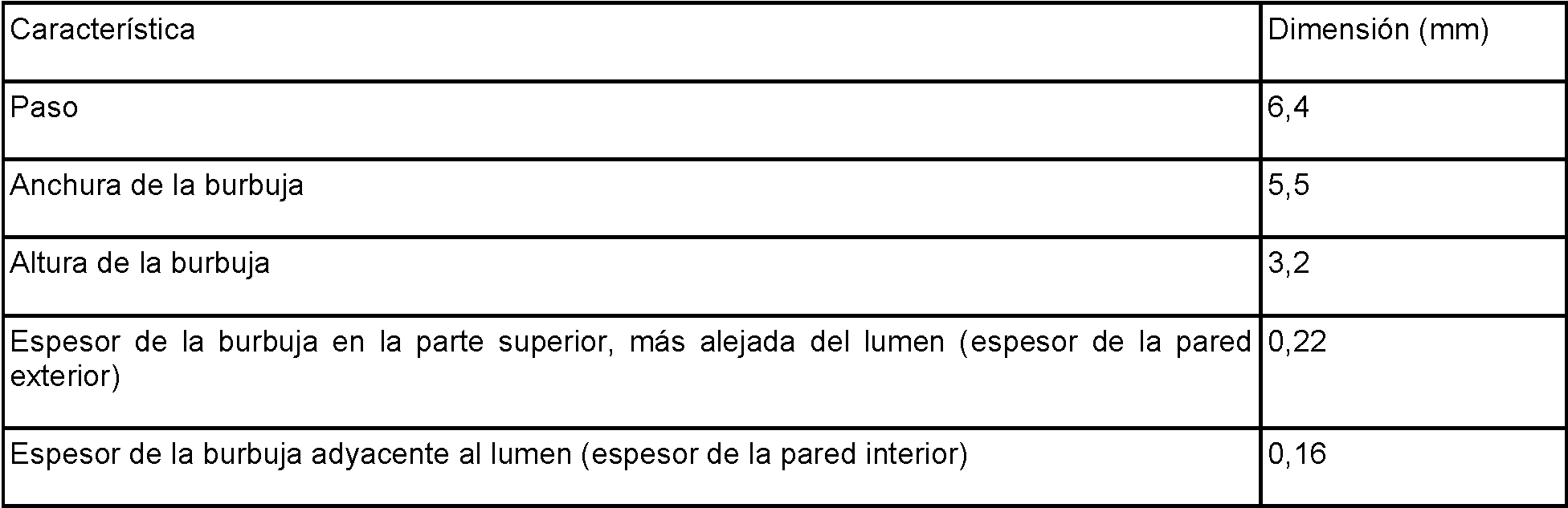
En otro ejemplo de realización, un tubo médico tiene las dimensiones aproximadas mostradas en la TABLA 6. Tabla 6In another embodiment, a medical tube has the approximate dimensions shown in TABLE 6 . Table 6

Preferentemente, los extremos bajos de los intervalos de la TABLA 6 se corresponden entre sí, y los extremos altos de los intervalos de la Tabla 6 se corresponden entre sí.Preferably, the low ends of the ranges in TABLE 6 correspond to each other, and the high ends of the ranges in Table 6 correspond to each other.
Las realizaciones de las TABLAS 5 y 6 pueden ser particularmente ventajosas para aplicaciones de apnea obstructiva del sueño.The embodiments of TABLES 5 and 6 may be particularly advantageous for obstructive sleep apnea applications.
Las TABLAS 7 , 8 y 9 proporcionan ejemplos de relaciones entre las dimensiones de las características del tubo para los tubos descritos en las TABLAS 3 , 4 y 6 respectivamente. TABLES 7 , 8, and 9 provide examples of tube feature dimension relationships for the tubes described in TABLES 3 , 4, and 6 respectively.
Tabla 7Table 7

Tabla 8Table 8

Tabla 9Table 9

Paso y/o diámetro variableVariable pitch and / or diameter
La descripción anterior desvela diversas configuraciones de paso y diámetro constantes. Sin embargo, algunas realizaciones pueden incorporar un paso variable y/o un diámetro variable.The above description discloses various constant diameter and pitch configurations. However, some embodiments may incorporate a variable pitch and / or a variable diameter.
Un paso variable puede ser deseable porque puede permitir que el calor suministrado al flujo de gas varíe a lo largo del tubo. La capacidad de controlar el lugar en el que es suministrado el calor en un tubo puede ser utilizada para controlar o reducir la precipitación dentro del tubo. Por ejemplo, puede ser alcanzado un punto de ajuste de la temperatura al final del tubo para una condición determinada, pero no es suficiente para evitar la precipitación dentro del tubo, especialmente en la entrada del tubo o cerca de ella, donde la temperatura del gas puede estar cerca de la temperatura del punto de rocío (alta humedad relativa). Ciertas realizaciones incluyen la constatación de que la redistribución de la fuente de calor para concentrarla cerca de la entrada del tubo puede ayudar a asegurar una mayor concentración axial de calor en esta región, Q(z) [W/m], en la que z es el desplazamiento axial del tubo, comenzando en el extremo de la unidad.A variable pitch may be desirable because it can allow the heat supplied to the gas flow to vary along the tube. The ability to control where heat is supplied in a tube can be used to control or reduce precipitation within the tube. For example, a temperature set point may be reached at the end of the tube for a given condition, but it is not sufficient to prevent precipitation within the tube, especially at or near the inlet of the tube, where the gas temperature it may be close to dew point temperature (high relative humidity). Certain embodiments include the finding that redistribution of the heat source to concentrate it near the tube inlet can help ensure a higher axial heat concentration in this region, Q (z) [W / m], where z is the axial displacement of the tube, starting at the end of the unit.
La FIG. 8A muestra un ejemplo de tubo compuesto 201 con paso variable. En este ejemplo, el tubo 201 tiene un paso más pequeño cerca del extremo de la unidad 801. De este modo, los filamentos de calentamiento 215 en esta región estarán más densamente espaciados, permitiendo un mayor calentamiento en esa parte del tubo 201 así como un mayor y más preciso control de la temperatura. El tubo 201 tiene un mayor paso en el extremo del paciente 803. El mayor espaciado entre los filamentos de calentamiento 215 puede permitir que los gases disminuyan su temperatura a medida que se acercan al paciente. Esto puede evitar que el paciente reciba gases demasiado calientes y puede reducir la formación de goteo. La FIG. 8B muestra el perfil de temperatura del tubo compuesto de la FIG. 8A. Otros perfiles de temperatura también son posibles y pueden ser personalizados para lograr efectos específicos deseados. FIG. 8A shows an example of a composite tube 201 with variable pitch. In this example, tube 201 has a smaller pitch near the end of unit 801 . In this way, the heating filaments 215 in this region will be more densely spaced, allowing greater heating in that part of tube 201 as well as greater and more precise temperature control. Tube 201 has a larger clearance at the end of the patient 803 . The greater spacing between the heating filaments 215 can allow the gases to decrease in temperature as they approach the patient. This can prevent the patient from getting too hot gases and can reduce drip formation. FIG. 8B shows the temperature profile of the composite tube of FIG. 8A . Other temperature profiles are also possible and can be customized to achieve specific desired effects.
La geometría del tubo 201 también afecta a las propiedades mecánicas del tubo. El aumento el tamaño de la burbuja del primer miembro alargado, incrementará la flexibilidad del tubo 201. Por el contrario, un tamaño de burbuja menor producirá una región más rígida del tubo 201. Al modificar la flexibilidad y la rigidez, las propiedades mecánicas del tubo 201 pueden personalizarse. Al variar el diámetro del tubo 201, es posible contar con un diámetro menor cerca de la interfaz con el paciente, lo que aumentará la comodidad del paciente, mejorará la estética y reducirá la invasividad de la interfaz.The geometry of tube 201 also affects the mechanical properties of the tube. Increasing the bubble size of the first elongated member will increase the flexibility of tube 201 . Conversely, a smaller bubble size will produce a stiffer region of tube 201 . By modifying flexibility and stiffness, the mechanical properties of tube 201 can be customized. By varying the diameter of the tube 201 , it is possible to have a smaller diameter near the patient interface, which will increase patient comfort, improve aesthetics, and reduce the invasiveness of the interface.
Propiedades adicionalesAdditional properties
Las TABLAS 10-13 muestran algunos ejemplos de propiedades de un tubo compuesto (etiquetado como "A"), descrito en la presente memoria, que tiene un filamento de calentamiento integrado dentro del segundo miembro alargado. A modo de comparación, también se presentan las propiedades de un tubo corrugado desechable Fisher & Paykel modelo RT100 (etiquetado como "B") que tiene un filamento de calentamiento enrollado helicoidalmente dentro del orificio del tubo. TABLES 10-13 show some examples of properties of a composite tube (labeled "A"), described herein, having an integrated heating filament within the second elongated member. For comparison, the properties of a Fisher & Paykel model RT100 disposable corrugated tube (labeled "B") having a helically wound heating filament within the tube hole are also presented.
La medición de la resistencia al flujo (RTF) se llevó a cabo según el Anexo A de la norma ISO 5367:2000(E). Los resultados se resumen en la TABLA 10. Como se observa a continuación, la RTF del tubo compuesto es menor que la RTF del tubo modelo RT100.The resistance to flow (RTF) measurement was carried out according to Annex A of ISO 5367: 2000 (E). The results are summarized in TABLE 10 . As seen below, the RTF of the composite tube is less than the RTF of the Model RT100 tube.
Tabla 10Table 10

El condensado o "goteo" dentro del tubo se refiere al peso del condensado recogido por día a un caudal de gas de 20 L/min y una temperatura ambiente de 18°C. El aire humidificado fluye a través del tubo continuamente desde una cámara. Los pesos del tubo se registran antes y después de cada día de prueba. Se realizan tres pruebas consecutivas, secando el tubo entre cada una de ellas. Los resultados son mostrados en la TABLA 11. Los resultados mostraron que la precipitación es significativamente menor en el tubo compuesto que en el tubo modelo RT100. Condensate or "drip" within the tube refers to the weight of condensate collected per day at a gas flow rate of 20 L / min and an ambient temperature of 18 ° C. Humidified air flows through the tube continuously from a chamber. Tube weights are recorded before and after each test day. Three consecutive tests are carried out, drying the tube between each of them. The results are shown in TABLE 11 . The results showed that the precipitation is significantly lower in the composite tube than in the model RT100 tube.
Tabla 11Table 11

El requisito de energía se refiere a la energía consumida durante la prueba de condensación. En esta prueba, el aire ambiente se mantuvo a 18°C. Las cámaras de humidificación (véase, por ejemplo, la cámara de humidificación 129 en la FIG. 1) fueron alimentadas por bases de calentamiento MR850. Los filamentos de calentamiento de los tubos se alimentaban independientemente de una fuente de alimentación de corriente continua. Se ajustaron diferentes caudales y se dejó que la cámara se asentara a 37°C en la salida de la cámara. A continuación, se modificó la tensión de CC de los circuitos para producir una temperatura de 40°C a la salida del circuito. Se registró la tensión necesaria para mantener la temperatura de salida y se calculó la potencia resultante. Los resultados son mostrados en la TABLA 12. Los resultados muestran que el tubo compuesto A utiliza una potencia significativamente mayor que el tubo B. Esto se debe a que el tubo B utiliza un filamento de calentamiento helicoidal en el orificio del tubo para calentar el gas de 37°C a 40°C. El tubo compuesto no tiende a calentar el gas tan rápidamente porque el filamento de calentamiento está en la pared del tubo (incrustado en el segundo miembro alargado). En cambio, el tubo compuesto está diseñado para mantener la temperatura del gas y evitar el goteo manteniendo el orificio del tubo a una temperatura superior al punto de rocío del gas humidificado.The power requirement refers to the energy consumed during the condensation test. In this test, the ambient air was kept at 18 ° C. The humidification chambers (see, for example, humidification chamber 129 in FIG. 1 ) were powered by MR850 heating bases. The heating filaments in the tubes were fed independently from a direct current power source. Different flow rates were set and the chamber was allowed to settle at 37 ° C at the chamber outlet. The DC voltage of the circuits was then modified to produce a temperature of 40 ° C at the outlet of the circuit. The voltage required to maintain the outlet temperature was recorded and the resulting power was calculated. The results are shown in TABLE 12 . The results show that Composite Tube A uses significantly more power than Tube B. This is because Tube B uses a helical heating filament in the tube hole to heat the gas from 37 ° C to 40 ° C. The composite tube does not tend to heat the gas as quickly because the heating filament is in the wall of the tube (embedded in the second elongated member). Instead, the composite tube is designed to maintain the temperature of the gas and prevent dripping by keeping the tube orifice at a temperature above the dew point of the humidified gas.
Tabla 12Table 12

La deflexión vertical puede ser utilizada para cuantificar la flexibilidad de un tubo de material compuesto. La deflexión vertical puede ser probada, por ejemplo, utilizando una prueba de flexión en tres puntos. Una primera muestra de 300 mm de longitud del tubo A y una segunda muestra de 300 mm de longitud del tubo B se probaron en una plantilla de flexibilidad. En la FIG. 9A se muestra un esquema de la sección transversal de la plantilla de flexibilidad. La plantilla 901 utilizó una varilla de 25 mm 903 con una masa fija de 120 g para aplicar una fuerza a cada tubo 201, que se colocó entre dos rodillos 905 y 907. Los rodillos estaban separados por una distancia de 150 mm. La fuerza ejercida por la varilla 903 era de aproximadamente 1,2 N (0,12 kg x 9,81 m/s2). Un esquema detallado de la sección transversal de los rodillos 905 y 907 se muestra en la FIG. 9B. Ambos rodillos 905 y 907 tenían las mismas dimensiones, que se muestran en la FlG. 9B. Se utilizó un instrumento Instron 5560 Test System para medir la carga y la extensión. Cada muestra de tubo se ensayó tres veces, midiendo la extensión del tubo contra la carga aplicada, para obtener las constantes de rigidez promedio respectivas. Las constantes de rigidez promedio para el tubo A y el tubo B se reproducen en la TABLA 13.Vertical deflection can be used to quantify the flexibility of a composite tube. Vertical deflection can be tested, for example, using a three-point bending test. A first 300 mm long sample from tube A and a second 300 mm long sample from tube B were tested on a flexibility jig. In FIG. 9A is a schematic of the cross section of the flexibility template. Template 901 used a 25mm rod 903 with a fixed mass of 120g to apply a force to each tube 201, which was placed between two rollers 905 and 907 . The rollers were separated by a distance of 150 mm. The force exerted by the rod 903 was approximately 1.2 N (0.12 kg x 9.81 m / s2). A detailed cross-sectional schematic of rollers 905 and 907 is shown in FIG. 9B. Both rollers 905 and 907 had the same dimensions, which are shown on the FlG. 9B. An Instron 5560 Test System instrument was used to measure load and extension. Each tube sample was tested three times, measuring the extension of the tube against the applied load, to obtain the respective average stiffness constants. The average stiffness constants for tube A and tube B are reproduced in TABLE 13 .
Tabla 13Table 13

El peso del tubo puede ser muy importante, particularmente para las aplicaciones de CPAP. Si un paciente experimenta menos peso cerca de la cara del paciente, el paciente estará más cómodo durante el sueño. Un tubo compuesto 201 más liviano no tirará de la cabeza del paciente en una dirección concreta tanto como un tubo más pesado. Para garantizar la comodidad del paciente, es posible especificar que la masa o el peso total en una región cercana al extremo del paciente del tubo compuesto 201 debe ser menor que un valor determinado. En ciertas realizaciones, la masa del tubo en los 300 mm más cercanos al extremo del paciente es menor que 24 g (o aproximadamente 24 g). De manera deseable, la masa del tubo en los 300 mm más cercanos al extremo del paciente es menor que 16 g (o aproximadamente 16 g). En ciertas realizaciones, la masa del tubo en los 300 mm más cercanos al extremo del paciente es menor que 15 g (o aproximadamente 15 g). También es posible especificar que la masa total del tubo compuesto sea menor que un valor determinado. En ciertas realizaciones, la masa del tubo es menor que 130 g (o aproximadamente 130 g). De manera deseable, la masa del tubo es menor que 120 g (o aproximadamente 120 g). En ciertas realizaciones, la masa del tubo es menor que 100 g (o aproximadamente 100 g). The weight of the tube can be very important, particularly for CPAP applications. If a patient experiences less weight near the patient's face, the patient will be more comfortable during sleep. A lighter composite tube 201 will not pull the patient's head in a particular direction as much as a heavier tube. To ensure patient comfort, it is possible to specify that the total mass or weight in a region near the patient end of the composite tube 201 should be less than a certain value. In certain embodiments, the mass of the tube in the nearest 300mm to the end of the patient is less than 24g (or about 24g). Desirably, the mass of the tube in the 300mm closest to the end of the patient is less than 16g (or about 16g). In certain embodiments, the mass of the tube in the nearest 300mm to the end of the patient is less than 15g (or about 15g). It is also possible to specify that the total mass of the composite tube is less than a certain value. In certain embodiments, the mass of the tube is less than 130g (or about 130g). Desirably, the mass of the tube is less than 120g (or about 120g). In certain embodiments, the mass of the tube is less than 100g (or about 100g).
La siguiente discusión describe ahora propiedades adicionales relacionadas con un tubo compuesto 201 con dos burbujas entre las envolturas del segundo miembro alargado 205, como se ha comentado anteriormente.The following discussion now describes additional properties related to a composite tube 201 with two bubbles between the shells of the second elongated member 205 , as discussed above.
Una primera muestra de tubo de 300 mm de longitud que comprende dos burbujas entre las envolturas del segundo miembro alargado 205 y una segunda muestra de tubo de 300 mm de longitud que comprende una burbuja entre las envolturas del segundo miembro alargado 205 fueron probadas cada una en la plantilla de flexibilidad 901 discutida anteriormente. La deflexión vertical se midió utilizando la posición del peso fijo con respecto a un soporte vertical 909 de la plantilla de flexibilidad, que se muestra en las fotografías de las FlGS. 9c a 9F. A first 300 mm long tube sample comprising two bubbles between the envelopes of the second elongated member 205 and a second 300 mm long tube sample comprising a bubble between the envelopes of the second elongated member 205 were each tested at flexibility template 901 discussed above. Vertical deflection was measured using the position of the fixed weight relative to a vertical support 909 of the flexibility jig, shown in the FlGS photographs. 9c to 9F.
La FlG. 9C muestra una vista en perspectiva frontal de la segunda muestra bajo prueba en la plantilla 901. La FlG. 9D muestra una vista en perspectiva trasera de la segunda muestra bajo prueba en la plantilla 901. La FlG. 9E muestra una vista en perspectiva frontal de la primera muestra bajo prueba en la plantilla 901. La FlG. 9F muestra una vista en perspectiva trasera de la primera muestra bajo prueba en la plantilla 901. Como se muestra en las FlGS. 9C a 9F, la segunda muestra mostrada en las FlGS. 9E y 9F tenía una deflexión vertical sustancialmente mayor que la primera muestra mostrada en las FlGS. 9C y 9D. Específicamente, la segunda muestra tenía una deflexión vertical de 3 mm, mientras que la primera muestra era mucho más flexible, teniendo una deflexión vertical de 42 mm.The FlG. 9C shows a front perspective view of the second sample under test on template 901. The FlG. 9D shows a rear perspective view of the second sample under test on template 901 . The FlG. 9E shows a front perspective view of the first sample under test on template 901 . The FlG. 9F shows a rear perspective view of the first sample under test on template 901 . As shown in the FlGS. 9C to 9F , the second sample shown on the FlGS. 9E and 9F had substantially greater vertical deflection than the first sample shown in the FlGS. 9C and 9D. Specifically, the second sample had a vertical deflection of 3mm, while the first sample was much more flexible, having a vertical deflection of 42mm.
Son realizadas pruebas de resistencia al aplastamiento en cuatro muestras de tubos utilizando una máquina lnstron configurada como se muestra en la fotografía de la FlG. 10A. El cilindro 1001 es sumergido en 16 mm desde la parte superior del tubo a una velocidad de 60 mm/min. La máquina lnstron tiene una célula de carga para medir con precisión la fuerza ejercida sobre un componente frente a la extensión. Se trazó la carga frente a la extensión, como se muestra en la FlG. 10B.Crush resistance tests are performed on four tube samples using an Instron machine configured as shown in the FlG photograph. 10A. Cylinder 1001 is immersed 16mm from the top of the tube at a speed of 60mm / min. The lnstron machine has a load cell to accurately measure the force exerted on a component versus extension. Load versus extension was plotted, as shown in the FlG. 10B .
La rigidez de aplastamiento para cada muestra fue hallada ajustando una línea de mejor ajuste a los datos de la FlG.The crush stiffness for each sample was found by fitting a line of best fit to the FlG data.
10B y calculando su gradiente. La rigidez de aplastamiento calculada para cada muestra se muestra en la TABLA 14A. En la TABLA 14A (y en otras partes de la presente divulgación), la designación "burbuja doble" se refiere a una muestra de tubo que comprende dos burbujas entre las envolturas del segundo miembro alargado 205, cuando la muestra se ve en sección transversal longitudinal. La designación "burbuja simple" se refiere a una muestra de tubo que comprende una sola burbuja entre las envolturas del segundo miembro alargado 205, cuando la muestra es observada en sección transversal longitudinal. La rigidez promedio al aplastamiento (medida en N/mm) representa la fuerza media máxima por unidad de anchura que no produce aplastamiento. 10B and calculating its gradient. The calculated crush stiffness for each sample is shown in TABLE 14A. In TABLE 14A (and elsewhere in this disclosure), the designation "double bubble" refers to a tube sample comprising two bubbles between the envelopes of the second elongated member 205 , when the sample is viewed in longitudinal cross section. . The designation "single bubble" refers to a tube sample comprising a single bubble between the shells of the second elongated member 205 , when the sample is viewed in longitudinal cross section. Average crush stiffness (measured in N / mm) represents the maximum average force per unit width that does not produce crush.
Tabla 14ATable 14A

Como se muestra en la tabla anterior, los tubos de burbuja simple tenían una rigidez promedio al aplastamiento de 3,86 N/mm, mientras que los tubos de burbuja doble tenían una rigidez promedio al aplastamiento de 3,21 N/mm. En otras palabras, los tubos de doble burbuja tenían una resistencia al aplastamiento aproximadamente un 16,8% menor que los tubos de burbuja simple. Sin embargo, ha sido observado que la rigidez al aplastamiento por unidad de espesor de los tubos de doble burbuja era aproximadamente de 165% del valor de los tubos de burbuja simple, como se muestra a continuación en la TABLA 14B.As shown in the table above, the single bubble tubes had an average crush stiffness of 3.86 N / mm, while the double bubble tubes had an average crush stiffness of 3.21 N / mm. In other words, the double bubble tubes had approximately 16.8% lower crush strength than the single bubble tubes. However, it has been observed that the crush stiffness per unit thickness of the double bubble tubes was approximately 165% of the value of the single bubble tubes, as shown below in TABLE 14B .
Tabla 14BTable 14B

Dicho de otro modo, cuando se tiene en cuenta el espesor de la burbuja exterior, el tubo de doble burbuja es aproximadamente 65% más resistente al aplastamiento que la variante de tubo de una sola burbuja. Al igual que las burbujas mostradas en las FIGS. 2F y 2G, las burbujas probadas en la configuración de doble burbuja son más altas que anchas, lo que resulta en más material en el plano vertical. Por lo tanto, se considera que la inesperada mejora en la resistencia al aplastamiento por unidad de espesor de la burbuja puede atribuirse a la red vertical adicional entre las cuentas que trabajan en la dirección del aplastamiento.In other words, when the thickness of the outer bubble is taken into account, the double bubble tube is approximately 65% more resistant to crushing than the single bubble tube variant. Like the bubbles shown in FIGS. 2F and 2G , the bubbles tested in the double bubble configuration are taller than they are wide, resulting in more material in the vertical plane. Therefore, it is considered that the unexpected improvement in crush strength per unit thickness of the bubble can be attributed to the additional vertical network between the beads working in the crushing direction.
También fueron realizadas pruebas de tracción en las muestras de tubo de burbuja simple y doble. Ambas muestras tenían 230 mm de longitud y fueron alargadas 15 mm a una velocidad de 10 mm/min. Fue medida la fuerza necesaria para alargar las muestras. Los resultados son mostrados en la TABLA 14C.Tensile tests were also performed on the single and double bubble tube samples. Both samples were 230 mm long and were elongated 15 mm at a speed of 10 mm / min. The force necessary to elongate the samples was measured. The results are shown in TABLE 14C .
Tabla 14CTable 14C

Como se muestra en la TABLA 14C, el tubo de doble burbuja era significativamente más extensible en el plano axial (longitudinal). Se considera que este aumento de la extensibilidad longitudinal se debe a que el tubo de burbuja simple tiene más material entre las perlas que trabajan en el plano axial.As shown in TABLE 14C , the double bubble tube was significantly more extensible in the axial (longitudinal) plane. This increase in longitudinal extensibility is considered to be due to the single bubble tube having more material between the beads working in the axial plane.
Propiedades térmicasThermal properties
En las realizaciones de un tubo compuesto 201 que incorpora un filamento de calentamiento 215, el calor puede perderse a través de las paredes del primer miembro alargado 203, lo que provoca un calentamiento desigual. Como ha sido explicado anteriormente, una forma de compensar estas pérdidas de calor es aplicar una fuente de calor externa en las paredes del primer miembro alargado 203, lo que ayuda a regular la temperatura y a contrarrestar la pérdida de calor. Sin embargo, también pueden utilizarse otros procedimientos para optimizar las propiedades térmicas. In embodiments of a composite tube 201 that incorporates a heating filament 215 , heat can be lost through the walls of the first elongated member 203 , causing uneven heating. As explained above, one way to compensate for these heat losses is to apply an external heat source to the walls of the first elongated member 203 , which helps to regulate the temperature and to counteract the heat loss. However, other procedures can also be used to optimize thermal properties.
Se hace referencia nuevamente a las FIGS. 5A a 5C, que demuestran configuraciones ejemplares para la altura de la burbuja (es decir, la altura de la sección transversal del primer miembro alargado 203 medida desde la superficie que da al lumen interior hasta la superficie que forma el diámetro exterior máximo) para mejorar las propiedades térmicas. Reference is again made to FIGS. 5A through 5C , demonstrating exemplary settings for bubble height (i.e., the cross-sectional height of the first elongated member 203 measured from the surface facing the inner lumen to the surface forming the maximum outer diameter) to improve thermal properties.
Las dimensiones de la burbuja pueden seleccionarse para reducir la pérdida de calor del tubo compuesto 201. Generalmente, el aumento de la altura de la burbuja aumenta la resistencia térmica efectiva del tubo 201, porque una mayor altura de la burbuja permite que el primer miembro alargado 203 contenga más aire aislante. Sin embargo, Ha sido descubierto que, a cierta altura de burbuja, los cambios en la densidad del aire provocan convección en el interior del tubo 201, aumentando así la pérdida de calor. Además, a cierta altura de la burbuja, el área de la superficie se vuelve tan grande que el calor que se pierde a través de la superficie supera los beneficios del aumento de la altura de la burbuja. Ciertas realizaciones incluyen estas realizaciones.The dimensions of the bubble can be selected to reduce heat loss from the composite tube 201 . Generally, increasing the height of the bubble increases the effective thermal resistance of tube 201 , because a greater height of the bubble allows the first elongated member 203 to contain more insulating air. However, it has been discovered that, at a certain bubble height, changes in air density cause convection within the tube 201 , thus increasing heat loss. Also, at a certain height of the bubble, the surface area becomes so great that the heat that is lost through the surface outweighs the benefits of increasing the height of the bubble. Certain embodiments include these embodiments.
El radio de curvatura y la curvatura de la burbuja pueden ser útiles para determinar una altura de burbuja deseable. La curvatura de un objeto se define como la inversa del radio de curvatura de ese objeto. Por lo tanto, cuanto mayor sea el radio de curvatura de un objeto, menos curvado será el objeto. Por ejemplo, una superficie plana tendría un radio de curvatura de ~ y, por tanto, una curvatura de 0.The radius of curvature and the curvature of the bubble can be helpful in determining a desirable bubble height. The curvature of an object is defined as the inverse of the radius of curvature of that object. Therefore, the greater the radius of curvature of an object, the less curved the object will be. For example, a flat surface would have a radius of curvature of ~ and therefore a curvature of 0.
La FIG. 5A muestra una sección transversal longitudinal de una porción superior de un tubo compuesto. La FIG. 5A muestra una realización de un tubo compuesto 201 donde la burbuja tiene una gran altura. En este ejemplo, la burbuja tiene un radio de curvatura relativamente pequeño y por lo tanto una gran curvatura. Además, la burbuja es aproximadamente tres o cuatro veces mayor en altura que la altura del segundo miembro alargado 205.FIG. 5A shows a longitudinal cross section of an upper portion of a composite tube. FIG. 5A shows an embodiment of a composite tube 201 where the bubble has a high height. In this example, the bubble has a relatively small radius of curvature and therefore a large curvature. Furthermore, the bubble is approximately three or four times greater in height than the height of the second elongated member 205 .
La FIG. 5B muestra una sección transversal longitudinal de una porción superior de otro tubo de material compuesto. La FIG. 5B muestra una realización de un tubo de material compuesto 201 en el que la burbuja está aplanada en la parte superior. En este ejemplo, la burbuja tiene un radio de curvatura muy grande pero una curvatura pequeña. Además, la burbuja tiene aproximadamente la misma altura que el segundo miembro alargado 205.FIG. 5B shows a longitudinal cross section of an upper portion of another composite tube. FIG. 5B shows an embodiment of a composite tube 201 in which the bubble is flattened on top. In this example, the bubble has a very large radius of curvature but a small curvature. Furthermore, the bubble is approximately the same height as the second elongated member 205 .
La FIG. 5C muestra una sección transversal longitudinal de una porción superior de otro tubo de material compuesto. La FIG. 5C muestra una realización de un tubo compuesto 201 donde la anchura de la burbuja es mayor que la altura de la burbuja. En este ejemplo, la burbuja tiene un radio de curvatura y la curvatura entre la de la FIG. 5A y la FIG.FIG. 5C shows a longitudinal cross section of an upper portion of another composite tube. FIG. 5C shows an embodiment of a composite tube 201 where the width of the bubble is greater than the height of the bubble. In this example, the bubble has a radius of curvature and the curvature between that of FIG. 5A and FIG.
5B, y el centro del radio para la porción superior de la burbuja está fuera de la burbuja (en comparación con la FIG. 5B , and the center of the radius for the upper portion of the bubble is outside the bubble (compared to FIG.
5A). Los puntos de inflexión en los lados izquierdo y derecho de la burbuja están aproximadamente en la mitad (en altura) de la burbuja (en contraposición a la porción inferior de la burbuja, como en la FIG. 5A). Además, la altura de la burbuja es aproximadamente el doble de la del segundo miembro alargado 205, resultando en una altura de burbuja entre la de la FIG. 5A y la FIG. 5B. 5A ). The inflection points on the left and right sides of the bubble are approximately in the middle (in height) of the bubble (as opposed to the bottom portion of the bubble, as in FIG. 5A ). Furthermore, the height of the bubble is approximately twice that of the second elongated member 205 , resulting in a bubble height between that of FIG. 5A and FIG. 5B.
La configuración de la FIG. 5A resultó en la menor pérdida de calor del tubo. La configuración de la FIG. 5B resultó en la mayor pérdida de calor del tubo. La configuración de la FIG. 5C tuvo una pérdida de calor intermedia entre las configuraciones de la FIG. 5A y 5B. Sin embargo, la gran superficie externa y la transferencia de calor por convección en la configuración de la FIG. 5A condujeron a un calentamiento ineficiente. De este modo, de las tres configuraciones de burbujas de las FIGS. 5A-5C, se determinó que la FIG. 5C tenía las mejores propiedades térmicas globales. La implicación práctica de esta eficiencia térmica es que, cuando la misma energía térmica fue introducida en los tres tubos, la configuración de la FIG. 5C permitió el mayor aumento de temperatura a lo largo del tubo. La burbuja de la FIG. 5C es lo suficientemente grande como para aumentar el volumen de aire aislante, pero no lo suficiente como para causar una pérdida de calor por convección significativa. Se determinó que la configuración de la FIG. 5B tenía las peores propiedades térmicas, es decir, que la configuración de la FIG. 5B permitía el menor aumento de temperatura a lo largo del tubo. La configuración de la FIG. 5A tenía propiedades térmicas intermedias y permitía un aumento de temperatura menor que la configuración de la FIG. 5C.The configuration of FIG. 5A resulted in the least heat loss from the tube. The configuration of FIG. 5B resulted in the highest heat loss from the tube. The configuration of FIG. 5C had intermediate heat loss between the configurations of FIG. 5A and 5B. However, the large external surface area and convective heat transfer in the configuration of FIG. 5A led to inefficient heating. Thus, of the three bubble configurations of FIGS. 5A-5C , it was determined that FIG. 5C had the best overall thermal properties. The practical implication of this thermal efficiency is that, when the same thermal energy was introduced into all three tubes, the configuration of FIG. 5C allowed the greatest increase in temperature along the tube. The bubble of FIG. 5C is large enough to increase the volume of insulating air, but not large enough to cause significant convective heat loss. It was determined that the configuration of FIG. 5B had the worst thermal properties, that is, the configuration of FIG. 5B allowed the least temperature rise along the tube. The configuration of FIG. 5A had intermediate thermal properties and allowed for a lower temperature rise than the configuration of FIG. 5C .
Debe apreciarse que aunque la configuración de la FIG. 5C puede ser preferente en ciertas realizaciones, otras configuraciones, incluyendo las de las FIGS. 5A, 5B y otras variaciones, pueden ser utilizadas en otras realizaciones según se desee.It should be appreciated that although the configuration of FIG. 5C may be preferred in certain embodiments, other configurations, including those of FIGS. 5A, 5B, and other variations, can be used in other embodiments as desired.
La TABLA 15 muestra la altura de la burbuja, el diámetro exterior del tubo y el radio de curvatura de las configuraciones mostradas en cada una de las FIGS. 5A, 5B y 5C.TABLE 15 shows bubble height, tube outer diameter, and radius of curvature of the configurations shown in each of FIGS. 5A, 5B and 5C .
Tabla 15Table 15

La TABLA 16A muestra la altura de la burbuja, el diámetro exterior y el radio de curvatura de otras configuraciones como las mostradas en las FIGS. 11A, 11B y 11C. TABLE 16A shows bubble height, outside diameter, and radius of curvature for other configurations as shown in FIGS. 11A, 11B and 11C.
Tabla 8ATable 8A

Cabe señalar que, en general, cuanto menor sea el radio de curvatura, más ajustado podrá doblarse el tubo alrededor de sí mismo sin que la burbuja se colapse o se "retuerza". Por ejemplo, la FIG. 11D muestra un tubo que ha sido doblado más allá de su radio de curvatura (específicamente, muestra el tubo de la FIG 11A doblado aproximadamente radio de curvatura de 5,7 mm), causando así un acodamiento en las paredes de la burbuja. El retorcimiento es generalmente indeseable, ya que puede desmerecer la apariencia del tubo, y puede perjudicar las propiedades térmicas del mismo.It should be noted that, in general, the smaller the bend radius, the tighter the tube can bend around itself without the bubble collapsing or "kinking." For example, FIG. 11D shows a tube that has been bent beyond its radius of curvature (specifically, it shows the tube of FIG 11A bent at approximately 5.7mm radius of curvature), thus causing kink in the walls of the bubble. Twisting is generally undesirable as it can detract from the appearance of the tube, and can impair the thermal properties of the tube.
En consecuencia, en algunas aplicaciones, las configuraciones con mayores propiedades de flexión (como las mostradas en las FIGS. 5A o 5B) pueden ser deseables a pesar de tener propiedades térmicas menos eficientes. En algunas aplicaciones, se ha encontrado que un tubo con un diámetro exterior de 25 mm a 26 mm (o aproximadamente 25 mm a aproximadamente 25 mm) proporciona un rendimiento satisfactorio. Debe apreciarse que aunque las configuraciones de las FIGS. 5A y 5B pueden ser preferentes en ciertas realizaciones, otras configuraciones, incluyendo las de las FIGS. 11A-11D y otras variaciones, pueden ser utilizadas en otras realizaciones según se desee. Consequently, in some applications, configurations with higher flexural properties (such as those shown in FIGS. 5A or 5B ) may be desirable despite having less efficient thermal properties. In some applications, a tube with an outer diameter of 25mm to 26mm (or about 25mm to about 25mm) has been found to provide satisfactory performance. It should be appreciated that although the configurations of FIGS. 5A and 5B may be preferred in certain embodiments, other configurations, including those of FIGS. 11A-11D and other variations, can be used in other embodiments as desired.
Se hace referencia nuevamente a las FIGS. 5C a 5F que demuestran ejemplos de colocación del elemento calefactor 215 con formas de burbuja similares para mejorar las propiedades térmicas. La ubicación del elemento calefactor 215 puede cambiar las propiedades térmicas dentro del tubo compuesto 201. Reference is again made to FIGS. 5C to 5F demonstrating examples of placement of heater element 215 with similar bubble shapes to improve thermal properties. The location of the heating element 215 can change the thermal properties within the composite tube 201.
La FIG. 5C muestra una sección transversal longitudinal de una porción superior de otro tubo compuesto. La FIG. 5C muestra una realización de un tubo de material compuesto 201 en el que los elementos calefactores 215 están situados centralmente en el segundo miembro alargado 205. Este ejemplo muestra los elementos de calentamiento 215 cerca uno del otro y no cerca de la pared de la burbuja.FIG. 5C shows a longitudinal cross section of an upper portion of another composite tube. FIG. 5C shows an embodiment of a composite tube 201 in which the heating elements 215 are centrally located in the second elongated member 205 . This example shows the heating elements 215 close to each other and not close to the bubble wall.
La FIG. 5D muestra una sección transversal longitudinal de una porción superior de otro tubo compuesto. La FIG. 5D muestra una realización de un tubo compuesto 201 en el que los elementos calefactores 215 están más separados, en comparación con la FIG. 5C, en el segundo miembro alargado 205. Estos elementos calefactores están más cerca de la pared de la burbuja y proporcionan una mejor regulación del calor dentro del tubo compuesto 201.FIG. 5D shows a longitudinal cross section of an upper portion of another composite tube. FIG. 5D shows an embodiment of a composite tube 201 in which the heating elements 215 are further apart, compared to FIG. 5C , in the second elongated member 205. These heating elements are closer to the bubble wall and provide better heat regulation within the composite tube 201.
La FIG. 5E muestra una sección transversal longitudinal de una porción superior de otro tubo compuesto. La FIG. 5E muestra una realización de un tubo compuesto 201 en el que los elementos calefactores 215 están espaciados uno encima del otro en el eje vertical del segundo miembro alargado 205. En este ejemplo, los elementos de calentamiento 215 están igualmente cerca de cada pared de burbuja.FIG. 5E shows a longitudinal cross section of an upper portion of another composite tube. FIG. 5E shows an embodiment of a composite tube 201 in which the heating elements 215 are spaced one above the other on the vertical axis of the second elongated member 205. In this example, the heating elements 215 are similarly close to each bubble wall.
La FIG.5F muestra una sección transversal longitudinal de una porción superior de otro tubo compuesto. La FIG. 5F muestra una realización de un tubo de material compuesto 201 en el que los elementos calefactores 215 están espaciados en los extremos opuestos del segundo miembro alargado 205. Los elementos calefactores 215 están cerca de la pared de la burbuja, especialmente en comparación con las FIGS. 5C-5E. FIG . 5F shows a longitudinal cross section of an upper portion of another composite tube. FIG. 5F shows an embodiment of a composite tube 201 in which the heating elements 215 are spaced at opposite ends of the second elongated member 205 . Heating elements 215 are close to the bubble wall, especially compared to FIGS. 5C-5E .
De las cuatro disposiciones de filamentos de las FIGS. 5C-5F, ha sido determinado que la FIG. 5F tenía las mejores propiedades térmicas. Debido a sus formas de burbuja similares, todas las configuraciones experimentaron una pérdida de calor similar desde el tubo. Sin embargo, cuando se introdujo la misma energía térmica en los tubos, la configuración de filamentos de la FIG. 5F permitió el mayor aumento de temperatura a lo largo del tubo, para la temperatura del gas a granel dentro del tubo. Se determinó que la configuración de la FIG. 5D tenía las siguientes mejores propiedades térmicas y permitía el siguiente mayor aumento de temperatura a lo largo del tubo. La configuración de la FIG. 5C fue la siguiente mejor. La configuración de la FIG. 5E tuvo el peor rendimiento y permitió el menor aumento de temperatura a lo largo del tubo, cuando se introdujo la misma cantidad de calor.Of the four filament arrangements of FIGS. 5C-5F , it has been determined that FIG. 5F had the best thermal properties. Due to their similar bubble shapes, all configurations experienced similar heat loss from the tube. However, when the same thermal energy was introduced into the tubes, the filament configuration of FIG. 5F allowed the greatest temperature rise along the tube, for the temperature of the bulk gas within the tube. It was determined that the configuration of FIG. 5D had the next best thermal properties and allowed for the next highest temperature rise along the tube. The configuration of FIG. 5C was the next best. The configuration of FIG. 5E had the worst performance and allowed the least temperature rise along the tube, when the same amount of heat was introduced.
Debe apreciarse que aunque la configuración de la FIG. 5F puede ser preferente en ciertas realizaciones, otras configuraciones, incluyendo las de las FIGS. 5C, 5D, 5E, y otras variaciones, pueden ser utilizadas en otras realizaciones según se desee. It should be appreciated that although the configuration of FIG. 5F may be preferred in certain embodiments, other configurations, including those of FIGS. 5C, 5D, 5E, and other variations, can be used in other embodiments as desired.
A continuación se hace referencia a las FIGS. 12A a 12C, que demuestran configuraciones ejemplares para el apilamiento del primer miembro alargado 203. Ha sido descubierto que la distribución de calor puede ser mejorada en ciertas realizaciones apilando múltiples burbujas. Estas realizaciones pueden ser más beneficiosas durante el uso un filamento de calentamiento interno 215. La FIG. 12A muestra una sección transversal longitudinal de una porción superior de otro tubo compuesto. La FIG. 12A muestra una sección transversal de un tubo compuesto 201 sin ningún apilamiento.Reference is now made to FIGS. 12A through 12C , which demonstrate exemplary configurations for stacking the first elongated member 203. It has been discovered that heat distribution can be improved in certain embodiments by stacking multiple bubbles. These embodiments may be most beneficial while using an internal heating filament 215 . FIG. 12A shows a longitudinal cross section of an upper portion of another composite tube. FIG. 12A shows a cross section of a composite tube 201 without any stacking.
La FIG. 12B muestra una sección transversal longitudinal de una porción superior de otro tubo compuesto. La FIG.FIG. 12B shows a longitudinal cross section of an upper portion of another composite tube. FIG.
12B muestra otro ejemplo de tubo compuesto 201 con burbujas apiladas. En este ejemplo, dos burbujas se apilan una encima de la otra para formar el primer miembro alargado 203. En comparación con la FIG. 12A, la altura total de la burbuja se mantiene, pero el paso de la burbuja es la mitad de la FIG. 12A. Además, la realización de la FIG. 12B tiene sólo una ligera reducción del volumen de aire. El apilamiento de las burbujas reduce la convección natural y la transferencia de calor en el espacio entre las burbujas 213 y disminuye la resistencia térmica total. La trayectoria del flujo de calor aumenta en las burbujas apiladas permitiendo que el calor se distribuya más fácilmente a través del tubo compuesto 201. 12B shows another example of a composite tube 201 with stacked bubbles. In this example, two bubbles are stacked on top of each other to form the first elongated member 203 . Compared to FIG. 12A , the total height of the bubble is maintained, but the pitch of the bubble is half that of FIG. 12A . Furthermore, the embodiment of FIG. 12B has only a slight reduction in air volume. Stacking of the bubbles reduces the natural convection and heat transfer in the space between the bubbles 213 and lowers the overall thermal resistance. The heat flow path increases in the stacked bubbles allowing the heat to be more easily distributed through the composite tube 201 .
La FIG. 12C muestra una sección transversal longitudinal de una porción superior de otro tubo compuesto. La FIG.FIG. 12C shows a longitudinal cross section of an upper portion of another composite tube. FIG.
12C muestra otro ejemplo de un tubo compuesto 201 con burbujas apiladas. En este ejemplo, tres burbujas están apiladas una encima de la otra para formar el primer miembro alargado 203. En comparación con la FIG. 12A, la altura total de las burbujas se mantiene, pero el paso de las burbujas es un tercio de la FIG. 12A. Además, la realización de la FIG. 12B tiene sólo una ligera reducción del volumen de aire. El apilamiento de las burbujas reduce la convección natural y la transferencia de calor en el espacio entre las burbujas 213. 12C shows another example of a composite tube 201 with stacked bubbles. In this example, three bubbles are stacked on top of each other to form the first elongated member 203 . Compared to FIG. 12A , the total height of the bubbles is maintained, but the pitch of the bubbles is one third of FIG. 12A . Furthermore, the embodiment of FIG. 12B has only a slight reduction in air volume. Stacking of the bubbles reduces the natural convection and heat transfer in the space between the bubbles 213 .
Con referencia ahora a la FIG. 13, se muestran posibles propiedades adicionales del segundo miembro alargado 205. El segundo miembro alargado 205 comprende uno o más cables coaxiales 1301 que tienen un conductor 1303 rodeado por una capa aislante 1305, una capa de blindaje 1307 y una capa de revestimiento 1309. En ciertas realizaciones, uno o más de los cables 1301 puede ser un cable multiaxial, es decir, tener múltiples conductores 1303 dispuestos dentro de la capa de aislamiento 1305. De esta manera, un único conjunto que contiene múltiples cables (incluyendo los cables de calentamiento y/o los cables del sensor) puede ser utilizado en el segundo miembro alargado 205, simplificando así el montaje y proporcionando cierto blindaje (a través de la capa de blindaje 1307) de las interferencias de RF y similares.Referring now to FIG. 13 , possible additional properties of the second elongated member 205 are shown . The second elongated member 205 comprises one or more coaxial cables 1301 having a conductor 1303 surrounded by an insulating layer 1305 , a shielding layer 1307, and a cladding layer 1309 . In certain embodiments, one or more of the cables 1301 may be a multiaxial cable, that is, have multiple conductors 1303 disposed within the insulation layer 1305 . In this way, a single assembly containing multiple cables (including the heating cables and / or the sensor cables) can be used in the second elongated member 205 , thus simplifying assembly and providing some shielding (through the layer of shielding 1307) from RF interference and the like.
En algunas realizaciones, uno o más cables de transmisión de datos pueden ser incluidos en el segundo miembro alargado 205. Los cables de transmisión de datos pueden comprender cables de fibra óptica. En al menos una realización, es incluido un único cable de fibra óptica en el segundo miembro alargado 205 y es usado en un modo pasivo. En un modo pasivo, en un primer extremo del cable, son proporcionados una fuente de luz y un sensor de luz. En un segundo extremo, es proporcionado un reflector. En el uso, la fuente de luz proporciona una cantidad de luz con ciertas propiedades hacia el reflector. El reflector refleja entonces la luz hacia el sensor de luz, que puede analizar la luz reflejada para determinar las propiedades de la luz. El reflector puede ser adaptado para cambiar la propiedad de la luz reflejada en función de una propiedad del sistema. Por ejemplo, el reflector puede ser utilizado para controlar la condensación dentro de la interfaz. El reflector puede comprender un material que, por ejemplo, cambie de color en función de la presencia de condensación en el segundo extremo. El reflector puede incluir alternativa o adicionalmente un material que cambie de color o similar dependiendo del nivel de humedad (ya sea humedad relativa o humedad absoluta), y/o la temperatura del gas en el segundo extremo, y/o la composición del gas como el O2 inhalado o el CO2 exhalado.In some embodiments, one or more data transmission cables can be included in the second elongated member 205 . The data transmission cables may comprise fiber optic cables. In at least one embodiment, a single fiber optic cable is included in the second elongated member 205 and is used in a passive mode. In a passive mode, at a first end of the cable, a light source and a light sensor are provided. At a second end, a reflector is provided. In use, the light source provides an amount of light with certain properties towards the reflector. The reflector then reflects the light back to the light sensor, which can analyze the reflected light to determine the properties of the light. The reflector can be adapted to change the property of the reflected light as a function of a property of the system. For example, the reflector can be used to control condensation within the interface. The reflector may comprise a material that, for example, changes color as a function of the presence of condensation at the second end. The reflector may alternatively or additionally include a material that changes color or the like depending on the level of humidity (either relative humidity or absolute humidity), and / or the temperature of the gas at the second end, and / or the composition of the gas as inhaled O 2 or exhaled CO 2.
Con referencia nuevamente a la FIG. 2B, en algunas realizaciones, un flujo de fluido (gas o líquido) puede pasar a lo largo del espacio dentro del primer miembro alargado 203. En tales realizaciones, es deseable que al menos una porción del primer miembro alargado 203 esté formada por un material transpirable. El término transpirable es utilizado la presente memoria para significar apreciablemente permeable al vapor de agua y sustancialmente impermeable a agua líquida y el flujo a granel de gases. Los materiales transpirables adecuados incluyen un material polimérico perfluorado activado con propiedades hidrofílicas extremas, como NAFION®, o un copolímero en bloque de poliéster hidrófilo, como SYMPATEx ®. Otros materiales adecuados son los polímeros incorporados comercialmente en los conductos EVAQUA™ y EVAQUA 2™ (Fisher & Paykel Healthcare Ltd., Auckland, Nueva Zelanda). Los materiales adecuados además son descritos en la Publicación de PCT WO 2011/077250, presentada el 22 de diciembre de 2010 y publicada el 30 de junio de 2011, y en la Patente de los Estados Unidos Núm. 6.769.431, presentada el 8 de mayo de 2001 y publicada el 3 de agosto de 2003.Referring again to FIG. 2B , in some embodiments, a flow of fluid (gas or liquid) can pass through the space within the first elongated member 203 . In such embodiments, it is desirable that at least a portion of the first elongated member 203 is formed of a breathable material. The term breathable is used herein to mean appreciably permeable to water vapor and substantially impervious to liquid water and the bulk flow of gases. Suitable breathable materials include an activated perfluorinated polymeric material with extreme hydrophilic properties, such as NAFION®, or a hydrophilic polyester block copolymer, such as SYMPATEx®. Other suitable materials are polymers incorporated commercially in EVAQUA ™ and EVAQUA 2 ™ conduits (Fisher & Paykel Healthcare Ltd., Auckland, New Zealand). Suitable materials are further described in PCT Publication WO 2011/077250, filed December 22, 2010 and published June 30, 2011, and in U.S. Patent No. 6,769,431, filed December 8, 2011. May 2001 and published on August 3, 2003.
El flujo a través del primer miembro alargado 203 puede ser útil para secar o humedecer el flujo de gas a través del lumen del tubo 201, según se desee. A la inversa, el flujo a través del lumen 207 del tubo 201 puede ser útil para secar o humedecer el flujo de gas a través del primer miembro alargado 203, según se desee. Los gases respiratorios exhalados pueden ser transportados a través del primer miembro alargado 203. Como otro ejemplo, puede ser transportado un líquido tal como agua líquida. Como otro ejemplo adicional, puede ser transportada una corriente de gas humidificado o saturado. Como otro ejemplo, una corriente de gas seco o una corriente de aire ambiental comprimido pueden ser transportadas. En las realizaciones anteriores, el primer miembro alargado 203 puede estar abierto en ambos extremos, para facilitar el flujo de fluido a través del primer miembro alargado 203. Un extremo del primer miembro alargado 203 puede estar conectado a una fuente adecuada, tal como una fuente de gas de respiración exhalado, agua líquida, gas humidificado, gas seco o aire comprimido, según se desee. El otro extremo puede conectarse a una salida adecuada o dejar que se ventile a la atmósfera.The flow through the first elongated member 203 may be useful to dry or wet the gas flow through the lumen of the tube 201 , as desired. Conversely, flow through lumen 207 of tube 201 may be useful to dry or wet the flow of gas through first elongated member 203 , as desired. Exhaled respiratory gases can be transported through the first elongated member 203 . As another example, a liquid such as liquid water can be transported. As yet another example, a stream of humidified or saturated gas can be carried. As another example, a stream of dry gas or a stream of compressed ambient air can be carried. In the above embodiments, the first elongated member 203 may be open at both ends, to facilitate fluid flow through the first elongated member 203. One end of the first elongated member 203 may be connected to a suitable source, such as a fountain. gas exhaled breath, liquid water, humidified gas, dry gas, or compressed air, as desired. The other end can be plugged into a suitable outlet or allowed to vent to atmosphere.
Por ejemplo, con referencia a la FIG. 2B, la porción 211 del primer miembro alargado 203 que forma el lumen 207 del tubo 201 puede estar formada del material transpirable, como se describió anteriormente. La porción 219 orientada hacia el exterior (orientada hacia la atmósfera ambiental y alejada del lumen) del primer miembro alargado 203 puede estar formada por un material impermeable, es decir, un material que no es apreciablemente permeable al vapor de agua, al agua líquida o al flujo de gases a granel, según lo descrito en otra parte de la presente divulgación. En el uso, una cantidad de fluido de humidificación (tal como agua) puede pasar a través del espacio formado por el primer miembro alargado 203. Como el fluido de humidificación se calienta (por ejemplo, por los filamentos de calentamiento 215 dispuestos en el segundo miembro alargado 205), una porción del fluido de humidificación tenderá a evaporarse. El vapor de agua puede entonces pasar a través de la porción respirable 211 al flujo de gas a granel a través del lumen 207, humidificando así el flujo de gas a granel. En dicha realización, la combinación del fluido de humidificación, el primer miembro alargado 203, y los filamentos de calentamiento 215 pueden proporcionar un medio para humidificar el flujo de gas dentro del lumen 207 de manera tal que un humidificador autónomo puede ser omitido del sistema. For example, referring to FIG. 2B , the portion 211 of the first elongated member 203 that forms the lumen 207 of the tube 201 may be formed of breathable material, as described above. The outwardly facing portion 219 (facing the ambient atmosphere and away from the lumen) of the first elongated member 203 may be formed of an impermeable material, that is, a material that is not appreciably permeable to water vapor, liquid water, or to the flow of bulk gases, as described elsewhere in this disclosure. In use, a quantity of humidifying fluid (such as water) can pass through the space formed by the first elongated member 203 . As the humidification fluid is heated (for example, by the heating filaments 215 arranged in the second elongated member 205 ), a portion of the humidification fluid will tend to evaporate. The water vapor can then pass through the breathable portion 211 to the bulk gas flow through the lumen 207 , thereby humidifying the bulk gas flow. In such an embodiment, the combination of the humidifying fluid, the first elongated member 203 , and the heating filaments 215 can provide a means to humidify the flow of gas within the lumen 207 such that a self-contained humidifier can be omitted from the system.
Como otro ejemplo, un flujo de gas puede pasar a lo largo del espacio dentro del primer miembro alargado 203. Por ejemplo, se pueden transportar gases respiratorios exhalados. Con referencia nuevamente a la FIG. 2B, el primer miembro alargado 203 o al menos la porción orientada hacia el exterior 219 del primer miembro alargado 203 está fabricado con un material transpirable, como ha sido descrito anteriormente. De esta manera, a medida que el gas exhalado se desplaza a lo largo de la longitud del primer miembro alargado 203, tenderá a secarse desde aproximadamente el 100% de humedad relativa en el extremo del paciente hasta un nivel de humedad reducido en el extremo opuesto.As another example, a gas flow can pass through the space within the first elongated member 203 . For example, exhaled respiratory gases can be transported. Referring again to FIG. 2B , the first elongated member 203 or at least the outwardly facing portion 219 of the first elongated member 203 is made of a breathable material, as described above. Thus, as the exhaled gas travels along the length of the first elongated member 203 , it will tend to dry from about 100% relative humidity at the end of the patient to a reduced humidity level at the opposite end. .
La coextrusión es un procedimiento adecuado para formar un primer miembro alargado 203 que comprende una porción (211 o 219, según la aplicación deseada) formada por un material transpirable y una porción (219 o 211, según la aplicación deseada) formada por un material impermeable.Coextrusion is a suitable process for forming a first elongated member 203 comprising a portion ( 211 or 219 , depending on the desired application) formed by a breathable material and a portion ( 219 or 211 , depending on the desired application) formed by an impermeable material. .
Además, aunque ciertas realizaciones anteriores se han descrito con referencia a un único primer miembro alargado 203 que comprende porciones transpirables e impermeables, debe apreciarse que los resultados deseados (como la humidificación del flujo de gas dentro del lumen 207) también pueden lograrse utilizando una pluralidad de primeros miembros alargados 203. En las FIGS. 12B, 12C, 37A y 37B se muestran realizaciones adecuadas.Furthermore, although certain prior embodiments have been described with reference to a single elongated first member 203 comprising breathable and waterproof portions, it should be appreciated that the desired results (such as humidification of the gas flow within lumen 207 ) can also be achieved using a plurality of of elongated first limbs 203 . In FIGS. 12B , 12C , 37A and 37B are shown suitable embodiments.
La FIG. 37A muestra una sección transversal del tubo que comprende dos primeros miembros alargados. Un primer miembro alargado 203a está dispuesto en la proximidad del lumen 207 del tubo. Un segundo primer miembro alargado 203b está orientado hacia la atmósfera ambiental y se aleja del lumen 207. La porción interior del primer miembro alargado 203a forma la pared del lumen 207. El primer miembro alargado 203a puede definir un conducto para un fluido de humidificación, como el agua líquida. El primer miembro alargado 203a puede estar formado por un material transpirable. A medida que el fluido de humidificación es calentado (por ejemplo, por los filamentos de calentamiento 215 dispuestos en el segundo miembro alargado 205), una parte del fluido de humidificación tenderá a evaporarse. El vapor puede entonces pasar a través de las paredes del primer miembro alargado 203a al flujo de gas a granel a través del lumen 207, humidificando así el flujo de gas a granel. En dicha realización, la combinación del fluido de humidificación, el primer miembro alargado 203a y los filamentos de calentamiento 215 pueden proporcionar un medio para humidificar el flujo de gas dentro del lumen 207 de manera tal que se puede omitir un humidificador independiente del sistema. Debe apreciarse que las dimensiones mostradas en la FIG. 37A no están necesariamente a escala. Por ejemplo, el primer miembro alargado 203a puede ser relativamente más grande, y el segundo miembro alargado 203b puede ser relativamente más pequeño como se muestra en la FIG. 12B. También debe apreciarse que los filamentos de calentamiento 215 no tienen que estar necesariamente alojados en el segundo miembro alargado 205. Por ejemplo, como se muestra en la FIG. 12B, el segundo miembro alargado puede ser omitido. Los filamentos de calentamiento 215 pueden alojarse, por ejemplo, en una porción del segundo primer miembro alargado 203b proximal al primer miembro alargado 203a.FIG. 37A shows a cross section of the tube comprising two first elongated members. A first elongated member 203a is disposed in the vicinity of the tube lumen 207 . A second elongated first member 203b faces the ambient atmosphere and is away from lumen 207 . The interior portion of the first elongated member 203a forms the wall of the lumen 207. The first elongated member 203a may define a conduit for a humidifying fluid, such as liquid water. The first elongated member 203a can be formed of a breathable material. As the humidification fluid is heated (for example, by the heating filaments 215 arranged in the second elongated member 205 ), a part of the humidification fluid will tend to evaporate. The vapor can then pass through the walls of the first elongated member 203a into the bulk gas flow through the lumen 207 , thereby humidifying the bulk gas flow. In such an embodiment, the combination of the humidifying fluid, the first elongated member 203a, and the heating filaments 215 can provide a means to humidify the gas flow within the lumen 207 such that a separate humidifier can be omitted from the system. It should be appreciated that the dimensions shown in FIG. 37A are not necessarily to scale. For example, the first elongated member 203a can be relatively larger, and the second elongated member 203b can be relatively smaller as shown in FIG. 12B . It should also be appreciated that the heating filaments 215 need not necessarily be housed in the second elongated member 205 . For example, as shown in FIG. 12B , the second elongated member can be omitted. Heating filaments 215 may be housed, for example, in a portion of the second elongated first member 203b proximal to the first elongated member 203a .
La FIG. 37B también muestra una sección transversal del tubo que comprende dos primeros miembros alargados. Un primer miembro alargado 203a está dispuesto en la proximidad del lumen 207 del tubo. Un segundo primer miembro alargado 203b está orientado hacia la atmósfera ambiental y se aleja del lumen 207. La porción interior del primer miembro alargado 203a forma parte de la pared del lumen 207. Una porción interna del segundo primer miembro alargado 203b también forma parte de la pared del lumen 207. Como se ha discutido anteriormente con referencia a la FIG. 37A, el primer miembro alargado 203a puede definir un conducto para un fluido de humidificación, tal como agua líquida, y la combinación del fluido de humidificación, el primer miembro alargado 203, y los filamentos de calentamiento 215 pueden proporcionar un medio para humidificar el flujo de gas dentro del lumen 207 de manera tal que un humidificador autónomo puede ser omitido del sistema. Nuevamente, debe apreciarse que las dimensiones mostradas en la FIG. 37B no están necesariamente a escala. Por ejemplo, el primer miembro alargado 203a puede ser relativamente más grande, y el segundo miembro alargado 203b puede ser relativamente más pequeño como se muestra en la FIG. 12B. También debe apreciarse que el filamento de calentamiento no tiene que estar necesariamente alojado en el segundo miembro alargado. Por ejemplo, como se muestra en la FIG. 12B, el segundo miembro alargado puede ser omitido. El filamento de calentamiento puede ser alojado, por ejemplo, en una porción del segundo primer miembro alargado 203b proximal al primer miembro alargado 203a. FIG. 37B also shows a cross section of the tube comprising two first elongated members. A first elongated member 203a is disposed in the vicinity of the tube lumen 207 . A second first elongated member 203b faces the ambient atmosphere and away from lumen 207. The interior portion of the first elongated member 203a forms part of the wall of lumen 207. An internal portion of the second first elongated member 203b also forms part of the lumen wall 207 . As discussed above with reference to FIG. 37A , the first elongated member 203a can define a conduit for a humidification fluid, such as liquid water, and the combination of the humidification fluid, the first elongated member 203 , and the heating filaments 215 can provide a means to humidify the flow. of gas within lumen 207 such that a self-contained humidifier can be omitted from the system. Again, it should be appreciated that the dimensions shown in FIG. 37B are not necessarily to scale. For example, the first elongated member 203a can be relatively larger, and the second elongated member 203b can be relatively smaller as shown in FIG. 12B . It should also be appreciated that the heating filament need not necessarily be housed in the second elongated member. For example, as shown in FIG. 12B , the second elongated member can be omitted. The heating filament may be housed, for example, in a portion of the second elongated first member 203b proximal to the first elongated member 203a .
Con referencia ahora a las FIGS. 14A-14E y 15A-15E, se muestran algunas variaciones de la configuración del tubo compuesto 201 que están adaptadas para proporcionar un mayor estiramiento lateral en el tubo compuesto 201. Las FIGS. 15A-15E muestran un estado estirado de los tubos compuestos mostrados en las FIGS. 14A-14E, respectivamente.Referring now to FIGS. 14A-14E and 15A-15E , some variations of the configuration of the composite tube 201 are shown that are adapted to provide greater lateral stretch in the composite tube 201 . FIGS. 15A-15E show a stretched state of the composite tubes shown in FIGS. 14A-14E , respectively.
Ciertas realizaciones incluyen la realización de que los tubos mostrados en las FIGS. 14A, 14B, y 14E comprenden un segundo miembro alargado 205 que tiene una forma que aumenta la capacidad de estiramiento. Por ejemplo, en la FIG. 14A, el segundo miembro alargado 205 es sustancialmente oblongo y tiene un perfil sustancialmente de la misma altura que el primer miembro alargado 203. Como se muestra en la FIG. 15A, esto permite que el segundo miembro alargado 205 se deforme hacia fuera hasta al menos el doble de la anchura en comparación con el segundo miembro alargado 205 en reposo. En las FIG. 14B y 14E, el segundo miembro alargado 205 tiene una forma de acordeón. Al estirarse, el segundo miembro alargado 205 puede, por tanto, tolerar una cantidad mayor de estiramiento por aplanamiento (como se muestra en las FIGS. 15B y 15E, respectivamente).Certain embodiments include the embodiment that the tubes shown in FIGS. 14A, 14B, and 14E comprise a second elongated member 205 that is shaped to increase stretchability. For example, in FIG. 14A , the second elongated member 205 is substantially oblong and has a profile of substantially the same height as the first elongated member 203 . As shown in FIG. 15A , this allows the second elongated member 205 to deform outwardly to at least twice the width compared to the second elongated member 205 at rest. In FIGS. 14B and 14E, the second elongated member 205 has an accordion shape. When stretched, the second elongated member 205 can therefore tolerate a greater amount of flattening stretching (as shown in FIGS. 15B and 15E, respectively).
En las FIGS. 14C y 14D, el primer miembro alargado 203 tiene una forma que le permite deformarse hacia afuera, permitiendo así un mayor estiramiento lateral (como se muestra en las FIGS. 15C y 15D, respectivamente).In FIGS. 14C and 14D, the first elongated member 203 has a shape that allows it to deform outwardly, thus allowing for greater lateral stretching (as shown in FIGS. 15C and 15D, respectively).
Circuitos médicosMedical circuits
A continuación se hace referencia a la FIG. 16, que muestra un ejemplo de circuito médico de acuerdo con al menos una realización. El circuito comprende uno o más tubos compuestos como ha sido descrito anteriormente, concretamente para el tubo inspiratorio 103 y/o el tubo espiratorio 117. Las propiedades del tubo inspiratorio 103 y del tubo espiratorio 117 son similares a los tubos descritos anteriormente con respecto a la FIG. 1. El tubo inspiratorio 103 tiene una entrada 109, que comunica con un humidificador 107, y una salida 113, a través de la cual son proporcionados gases humidificados al paciente 101. El tubo espiratorio 117 también tiene una entrada 109, que recibe los gases humidificados exhalados por el paciente, y una salida 113. Como ha sido descrito anteriormente con respecto a la FIG. 1, la salida 113 del tubo espiratorio 117 puede ventilar los gases exhalados a la atmósfera, a la unidad de ventilador/soplador 105, a un depurador/filtro de aire (no mostrado), o a cualquier otro lugar adecuado.Reference is now made to FIG. 16 , showing an example of a medical circuit according to at least one embodiment. The circuit comprises one or more composite tubes as described above, specifically for the inspiratory tube 103 and / or the expiratory tube 117 . The properties of the inspiratory tube 103 and expiratory tube 117 are similar to the tubes described above with respect to FIG. 1. Inspiratory tube 103 has an inlet 109 , which communicates with a humidifier 107 , and an outlet 113 , through which humidified gases are provided to the patient 101 . The expiratory tube 117 also has an inlet 109 , which receives the humidified gases exhaled by the patient, and an outlet 113 . As previously described with respect to FIG. 1 , the outlet 113 of the expiratory tube 117 can vent the exhaled gases to the atmosphere, to the fan / blower unit 105 , to an air cleaner / filter (not shown), or to any other suitable location.
Como ha sido descrito anteriormente, los filamentos de calentamiento 215 pueden colocarse dentro del tubo inspiratorio 103 y/o el tubo espiratorio 117 para reducir el riesgo de goteo en los tubos manteniendo la temperatura de la pared del tubo por encima de la temperatura del punto de rocío.As previously described, the heating filaments 215 can be placed within the inspiratory tube 103 and / or the expiratory tube 117 to reduce the risk of dripping into the tubes by keeping the tube wall temperature above the set point temperature. Dew.
Componente de un sistema de insuflaciónComponent of an insufflation system
La cirugía laparoscópica, también denominada cirugía mínimamente invasiva (CMI), o cirugía de ojo de cerradura, es una técnica quirúrgica moderna en la que las operaciones en el abdomen se realizan a través de pequeñas incisiones (normalmente de 0,5 a 1,5 cm) en comparación con las incisiones más grandes que se necesitan en los procedimientos quirúrgicos tradicionales. La cirugía laparoscópica incluye operaciones dentro de las cavidades abdominal o pélvica. Durante la cirugía laparoscópica con insuflación, puede ser conveniente que el gas de insuflación (normalmente CO2) sea humedecido antes de pasar a la cavidad abdominal. Esto puede ayudar a evitar la "desecación" de los órganos internos del paciente y puede disminuir el tiempo necesario para la recuperación de la cirugía. Los sistemas de insuflación suelen constar de cámaras humidificadoras que contienen una cantidad de agua. El humidificador suele incluir una placa calefactora que calienta el agua para crear un vapor de agua que se transmite a los gases entrantes para humidificarlos. Los gases son transportados fuera del humidificador con el vapor de agua.Laparoscopic surgery, also called minimally invasive surgery (MIC), or keyhole surgery, is a modern surgical technique in which operations on the abdomen are performed through small incisions (usually 0.5 to 1.5 cm) compared to the larger incisions needed in traditional surgical procedures. Laparoscopic surgery includes operations within the abdominal or pelvic cavities. During laparoscopic insufflation surgery, it may be desirable for the insufflation gas (usually CO 2 ) to be moistened before passing into the abdominal cavity. This can help prevent "drying out" of the patient's internal organs and may decrease the time it takes to recover from surgery. Insufflation systems usually consist of humidifying chambers that contain a quantity of water. The humidifier usually includes a heating plate that heats the water to create a water vapor that is transmitted to the incoming gases to humidify them. The gases are transported out of the humidifier with the water vapor.
A continuación se hace referencia a la FIG. 17, que muestra un sistema de insuflación 1701, de acuerdo con al menos una realización. El sistema de insuflación 1701 incluye un insuflador 1703 que produce una corriente de gases de insuflación a una presión mayor que la atmosférica para su entrega en la cavidad abdominal o peritoneal del paciente 1705. Los gases pasan a un humidificador 1707, que incluye una base calefactora 1709 y una cámara humidificadora 1711, con la cámara 1711 en uso en contacto con la base calefactora 1709 para que la base calefactora 1709 proporcione calor a la cámara 1711. En el humidificador 1707, los gases de insuflación pasan a través de la cámara 1711 para que sean humedecidos hasta un nivel adecuado de humedad.Reference is now made to FIG. 17 , showing an insufflation system 1701 , according to at least one embodiment. Insufflation system 1701 includes insufflator 1703 that produces a stream of insufflation gases at a pressure greater than atmospheric for delivery into the abdominal or peritoneal cavity of patient 1705 . The gases pass to a humidifier 1707 , which includes a heater base 1709 and a humidifier chamber 1711 , with the chamber 1711 in use in contact with the heater base 1709 for the heater base 1709 to provide heat to the chamber 1711 . In humidifier 1707 , insufflation gases pass through chamber 1711 to be moistened to a suitable humidity level.
El sistema 1701 incluye un conducto de suministro 1713 que se conecta entre la cámara humidificadora 1711 y la cavidad peritoneal del paciente 1705 o el sitio quirúrgico. El conducto 1713 tiene un primer extremo y un segundo extremo, estando el primer extremo conectado a la salida de la cámara humidificadora 1711 y recibiendo los gases humidificados de la cámara 1711. El segundo extremo del conducto 1713 es colocado en el sitio quirúrgico o la cavidad peritoneal del paciente 1705 y los gases de insuflación humidificados se desplazan desde la cámara 1711, a través del conducto 1713 y dentro del sitio quirúrgico para insuflar y expandir el sitio quirúrgico o la cavidad peritoneal. El sistema también incluye un controlador (no mostrado) que regula la cantidad de humedad suministrada a los gases mediante el control de la potencia suministrada a la base del calentador 1709. El controlador también puede utilizarse para controlar el agua en la cámara del humidificador 1711. Se muestra un sistema de evacuación de humos 1715 que sale de la cavidad corporal del paciente 1705.System 1701 includes a delivery conduit 1713 that connects between humidifier chamber 1711 and the patient's peritoneal cavity 1705 or the surgical site. The conduit 1713 has a first end and a second end, the first end being connected to the outlet of the humidifier chamber 1711 and receiving the humidified gases from the chamber 1711 . The second end of conduit 1713 is placed in the surgical site or peritoneal cavity of patient 1705 and the humidified insufflation gases travel from chamber 1711, through conduit 1713 and into the surgical site to inflate and expand the surgical site or the peritoneal cavity. The system also includes a controller (not shown) that regulates the amount of moisture supplied to the gases by controlling the power supplied to the base of the 1709 heater. The controller can also be used to control the water in the 1711 humidifier chamber. A fume evacuation system 1715 is shown exiting the body cavity of patient 1705 .
El sistema de evacuación de humos 1715 puede utilizarse junto con el sistema de insuflación 1701 descrito anteriormente o puede utilizarse con otros sistemas de insuflación adecuados. El sistema de evacuación de humos 1715 comprende un miembro de descarga o escape 1717, un conjunto de descarga 1719 y un filtro 1721. La rama de descarga 1717 se conecta entre el filtro 1721 y el conjunto de descarga 1719, que en uso está situado en o adyacente al sitio quirúrgico del paciente 1705 o a la cavidad peritoneal. El miembro de descarga 1717 es un tubo autónomo (es decir, el tubo es capaz de soportar su propio peso sin colapsar) con dos extremos abiertos: un extremo del sitio operativo y un extremo de salida.The smoke evacuation system 1715 can be used in conjunction with the insufflation system 1701 described above or can be used with other suitable insufflation systems. The smoke evacuation system 1715 comprises a discharge or exhaust member 1717 , a discharge assembly 1719, and a filter 1721. Discharge limb 1717 connects between filter 1721 and discharge assembly 1719 , which in use is located at or adjacent to the surgical site of the patient 1705 or to the peritoneal cavity. The discharge member 1717 is a self-contained tube (that is, the tube is capable of supporting its own weight without collapsing) with two open ends: an operating site end and an outlet end.
Al menos una realización incluye la constatación de que el uso de un tubo compuesto como conducto 1713 puede proporcionar gases humidificados al sitio quirúrgico del paciente 1705 con una pérdida de calor minimizada de los gases humidificados.At least one embodiment includes the realization that the use of a composite tube as conduit 1713 can provide humidified gases to the surgical site of patient 1705 with minimized heat loss from the humidified gases.
Tubo coaxialCoaxial tube
Un tubo de respiración coaxial también puede comprender un tubo compuesto como el descrito anteriormente. En un tubo de respiración coaxial, un primer espacio de gas es una extremidad inspiratoria o una extremidad espiratoria, y el segundo espacio de gas es el otro de la extremidad inspiratoria o de la extremidad espiratoria. Es proporcionado un pasaje de gas entre la entrada de dicha extremidad inspiratoria y la salida de dicha extremidad inspiratoria, y es proporcionado un pasaje de gas entre la entrada de dicha extremidad espiratoria y la salida de dicha extremidad espiratoria. En una realización, el primer espacio de gas es dicha extremidad inspiratoria, y el segundo espacio de gas es dicha extremidad espiratoria. Alternativamente, el primer espacio de gas puede ser la extremidad espiratoria, y el segundo espacio de gas puede ser la extremidad inspiratoria.A coaxial breathing tube can also comprise a composite tube as described above. In a coaxial breathing tube, a first gas space is an inspiratory limb or an expiratory limb, and the second gas space is the other of the inspiratory limb or expiratory limb. A gas passage is provided between the inlet of said inspiratory limb and the outlet of said inspiratory limb, and a gas passage is provided between the inlet of said expiratory limb and the outlet of said expiratory limb. In one embodiment, the first gas space is said inspiratory limb, and the second gas space is said expiratory limb. Alternatively, the first gas space can be the expiratory limb, and the second gas space can be the inspiratory limb.
Se hace referencia a la FIG. 18, que muestra un tubo coaxial 1801 de acuerdo con al menos una realización. En este ejemplo, el tubo coaxial 1801 se proporciona entre un paciente 1801 y un respirador 1805. Los gases espiratorios y los gases inspiratorios fluyen cada uno en uno de los tubos interiores 1807 o en el espacio 1809 entre el tubo interior 1807 y el tubo exterior 1811. Se apreciará que el tubo exterior 1811 puede no estar exactamente alineado con el tubo interior 1807. En cambio, "coaxial" se refiere a un tubo situado dentro de otro tubo.Reference is made to FIG. 18 , showing a coaxial tube 1801 according to at least one embodiment. In this example, the coaxial tube 1801 is provided between a patient 1801 and a ventilator 1805. Expiratory gases and inspiratory gases each flow in one of the inner tubes 1807 or in the space 1809 between the inner tube 1807 and the outer tube 1811 . It will be appreciated that the outer tube 1811 may not be exactly aligned with the inner tube 1807 . Instead, "coaxial" refers to a tube located within another tube.
Por razones de transferencia de calor, el tubo interior 1807 puede transportar los gases inspiratorios en el espacio 1813 del mismo, mientras que los gases espiratorios son transportados en el espacio 1809 entre el tubo interior 1807 y el tubo exterior 1811. Esta configuración del flujo de aire se indica con flechas. Sin embargo, también es posible una configuración inversa, en la que el tubo exterior 1811 transporta los gases inspiratorios y el tubo interior 1807 transporta los gases espiratorios.For heat transfer reasons, the inner tube 1807 can transport the inspiratory gases in the space 1813 thereof, while the expiratory gases are transported in the space 1809 between the inner tube 1807 and the outer tube 1811. This configuration of the flow of air is indicated by arrows. However, a reverse configuration is also possible, in which the outer tube 1811 carries the inspiratory gases and the inner tube 1807 carries the expiratory gases.
En al menos una realización, el tubo interior 1807 está formado por un tubo corrugado, tal como un tubo desechable Fisher & Paykel modelo RT100. El tubo exterior 1811 puede estar formado por un tubo compuesto, como ha sido descrito anteriormente.In at least one embodiment, inner tube 1807 is formed of a corrugated tube, such as a Fisher & Paykel model RT100 disposable tube. The outer tube 1811 can be formed of a composite tube, as previously described.
Con un tubo coaxial 1801, el respirador 1805 puede no notar una fuga en el tubo interior 1807. Dicha fuga puede provocar un cortocircuito en el paciente 1801, lo que significa que el paciente 1801 no recibirá suficiente oxígeno. Dicho cortocircuito puede detectarse mediante la colocación de un sensor en el extremo del paciente del tubo coaxial 1801. Este sensor puede estar situado en el conector del extremo del paciente 1815. Un cortocircuito más cercano al respirador 1805 hará que el paciente 1801 continúe reinhalando el volumen de aire cercano al paciente 1801. Esto conducirá a un aumento de la concentración de dióxido de carbono en el espacio de flujo inspiratorio 1813 cerca del paciente 1801, que puede ser detectado directamente por un sensor de CO2. Dicho sensor puede comprender cualquiera de un número de tales sensores como los disponibles actualmente en el mercado. Alternativamente, esta re-respiración puede ser detectada mediante la monitorización de la temperatura de los gases en el conector del extremo del paciente 1815, en el que un aumento de la temperatura por encima de un nivel predeterminado indica que se está produciendo una re-respiración.With a 1801 coaxial tube, the 1805 respirator may not notice a leak in the 1807 inner tube. Such a leak can short-circuit patient 1801 , meaning that patient 1801 will not receive enough oxygen. Such a short can be detected by placing a sensor on the patient end of the coaxial tube 1801. This sensor can be located on the patient end connector 1815. A short closer to the ventilator 1805 will cause the patient 1801 to continue rebreathing the volume. of air near patient 1801. This will lead to an increase in the concentration of carbon dioxide in inspiratory flow space 1813 near patient 1801, which can be directly detected by a CO 2 sensor. Said sensor can comprise any of a number of such sensors as those currently available on the market. Alternatively, this rebreathing can be detected by monitoring the temperature of the gases in the patient end connector 1815 , where a rise in temperature above a predetermined level indicates that rebreathing is occurring. .
Además de lo anterior, para reducir o eliminar la formación de condensación dentro del tubo interior 1807 o del tubo exterior 1811, y para mantener una temperatura sustancialmente uniforme en el flujo de gases a través del tubo coaxial 1801, puede proporcionarse un calentador, tal como un filamento de calentamiento de resistencia, dentro del tubo interior 1807 o del tubo exterior 1811, dispuesto dentro de los espacios de gases 1809 o 1813, o dentro de las propias paredes del tubo interior 1807 o del tubo exterior 1811.In addition to the foregoing, to reduce or eliminate condensation formation within inner tube 1807 or outer tube 1811 , and to maintain a substantially uniform temperature in the flow of gases through coaxial tube 1801 , a heater may be provided, such as a resistance heating filament, within the inner tube 1807 or the outer tube 1811 , disposed within the gas spaces 1809 or 1813 , or within the walls of the inner tube 1807 or the outer tube 1811 .
Cánulas nasales y otras interfaces de pacientesNasal cannulas and other patient interfaces
A continuación se hace referencia a la FIG. 19A, que muestra el tubo compuesto 201 en uso con una interfaz de paciente de cánula nasal 1901. En este ejemplo, la interfaz del paciente 1901 se coloca en la cara del paciente 1903 con el arnés 1905 asegurado alrededor de la parte posterior de la cabeza del paciente 1901. La interfaz del paciente incluye un cuerpo de cánula 1907 y un tubo de suministro 1909. Un tubo compuesto 201, como se ha descrito, se comunica con el tubo de suministro 1909 para proporcionar gases inspiratorios a la interfaz del paciente 1901. Reference is now made to FIG. 19A , showing composite tube 201 in use with a 1901 nasal cannula patient interface. In this example, the 1901 patient interface is placed on the face of the 1903 patient with the 1905 headgear secured around the back of the head. 1901 patient interface. The patient interface includes a cannula body 1907 and a delivery tube 1909 . A composite tube 201 , as described, communicates with delivery tube 1909 to provide inspiratory gases to patient interface 1901 .
En el pasado, el tubo de suministro 1909 ha sido utilizado para desacoplar el peso del tubo de respiración calentado de la interfaz del paciente 1901. Los tubos de suministro 1909 utilizados anteriormente consistían en una longitud de tubo flexible. Era importante que el tubo de suministro 1909 fuera liviano para que la masa del tubo de suministro 1909 no arrastrara la interfaz del paciente 1901 de la cara del paciente. Los tubos calentados eran sustancialmente más voluminosos y pesados que los tubos no calentados. Por lo tanto, los tubos de suministro 1909 utilizados anteriormente no se calentaban. Para lograr una flexibilidad satisfactoria, los tubos de suministro 1909 utilizados anteriormente también tenían malas propiedades de aislamiento. Sin un buen aislamiento y calentamiento, el goteo en los tubos de suministro 1909 era un problema. Por lo tanto, los tubos de suministro 1909 se mantuvieron lo más cortos posible para minimizar el goteo. Sin embargo, la corta longitud no impedía sistemáticamente que el peso del tubo de respiración calentado arrastrara la interfaz del paciente 1901. Por lo tanto, los tubos de suministro utilizados anteriormente tienen una serie de inconvenientes. In the past , delivery tube 1909 has been used to uncouple the weight of the heated breathing tube from the patient interface 1901 . The supply tubes 1909 used previously consisted of a length of flexible tube. It was important that the delivery tube 1909 be lightweight so that the mass of the delivery tube 1909 did not drag the patient interface 1901 away from the patient's face. The heated tubes were substantially bulkier and heavier than the unheated tubes. Therefore, the 1909 supply tubes used previously they were not heated. To achieve satisfactory flexibility, the supply tubes 1909 used previously also had poor insulation properties. Without good insulation and heating, dripping in the 1909 supply tubes was a problem. Therefore, the 1909 supply tubes were kept as short as possible to minimize dripping. However, the short length did not consistently prevent the weight of the heated breathing tube from dragging the 1901 patient interface. Therefore, the supply tubes used previously have a number of drawbacks.
Los tubos compuestos 201 descritos en la presente memoria proporcionan un buen aislamiento manteniendo una buena flexibilidad y un peso liviano. De este modo, en algunas realizaciones, el tubo de suministro 1909 puede ser un tubo compuesto 201. Los tubos compuestos 201 pueden proporcionar propiedades de aislamiento mejoradas con respecto a los tubos de suministro previamente conocidos en la técnica. Además, la longitud del tubo de entrega puede ser más larga y proporcionar un mejor desacoplamiento del arrastre del tubo. El tubo de suministro 201 de material compuesto puede tener opcionalmente filamentos de calentamiento (no mostrados) en el segundo miembro alargado (no mostrado). Los filamentos de calentamiento, si están presentes, pueden proporcionar una entrada de calor. Alternativamente, los filamentos de calentamiento pueden proporcionar soporte estructural para el segundo miembro alargado sin ser energizados.The composite tubes 201 described herein provide good insulation while maintaining good flexibility and light weight. Thus, in some embodiments, delivery tube 1909 may be composite tube 201 . Composite tubes 201 can provide improved insulation properties over supply tubes previously known in the art. In addition, the length of the delivery tube can be longer and provide better decoupling of the tube drive. Composite supply tube 201 may optionally have heating filaments (not shown) in the second elongated member (not shown). Heating filaments, if present, can provide heat input. Alternatively, the heating filaments can provide structural support for the second elongated member without being energized.
La longitud del tubo de suministro de material compuesto 201 sin calentar puede ser mayor que la longitud de una extensión normal sin calentar, manteniendo la misma o menor cantidad de pérdida de calor debido a las mejores propiedades de aislamiento del tubo de material compuesto 201. Una mayor longitud del tubo de suministro 1909 es beneficiosa para evitar que el movimiento del paciente arrastre las conexiones del tubo. Una mayor longitud de extensión también permitirá un mejor movimiento de la cabeza sin comprometer la comodidad del paciente.The length of the unheated composite supply tube 201 can be longer than the length of a normal unheated extension, maintaining the same or less amount of heat loss due to the better insulation properties of the composite tube 201 . Longer length of delivery tube 1909 is beneficial in preventing patient movement from dragging tube connections. A longer extension length will also allow for better head movement without compromising patient comfort.
Además, ciertas realizaciones incluyen la comprensión de que la eliminación de un tubo de entrega separado 1909 puede tener una serie de beneficios, discutidos a continuación. De este modo, como se muestra en la FIG. 19B, el tubo de suministro 1909 y el tubo compuesto 201 pueden ser deseablemente un componente unitario, que se extiende hasta el cuerpo de la cánula 1907. Additionally, certain embodiments include the understanding that eliminating a separate delivery tube 1909 can have a number of benefits, discussed below. Thus, as shown in FIG. 19B , delivery tube 1909 and composite tube 201 may desirably be a unitary component, extending into the cannula body 1907.
En una interfaz de paciente típica 1901, un tubo calentado (en lugar del tubo compuesto 201 de la FIG. 19A) suministra gases inspiratorios a un tubo de suministro no calentado 1909. La temperatura de los gases inspiratorios puede experimentar pérdidas térmicas significativas (por ejemplo, 20°C o más o alrededor) a lo largo de la longitud del tubo de suministro no calentado 1909. Para compensar, la temperatura en el extremo del paciente del tubo calentado se mantiene más alta que la temperatura requerida realmente suministrada al paciente 1901. Además, la condensación puede llover a medida que la temperatura desciende en el tubo de suministro 1909. Ha sido observado que extender un tubo compuesto calentado 201 al cuerpo de la cánula 1907 en lugar del tubo de suministro 1909, como se muestra en la FIG. 19B, puede reducir los requisitos de energía de entrada, ya que el extremo del paciente del tubo compuesto 201 puede mantenerse a una temperatura más baja. Esta configuración también puede reducir el goteo al eliminar el tubo de entrega 1909 no calentado de la interfaz del paciente.In a typical patient interface 1901, a heated tube (instead of the composite tube 201 of FIG. 19A ) delivers inspiratory gases to an unheated delivery tube 1909 . The temperature of the inspiratory gases can experience significant thermal losses (for example, 20 ° C or more or around) along the length of the unheated delivery tube 1909 . To compensate, the temperature at the patient end of the heated tube is kept higher than the required temperature actually delivered to the patient 1901 . Also, condensation can rain down as the temperature drops in supply tube 1909 . It has been observed that extending a heated composite tube 201 to the cannula body 1907 in place of the delivery tube 1909 , as shown in FIG. 19B , you can reduce the input power requirements, as the patient end of the composite tube 201 can be kept at a lower temperature. This configuration can also reduce dripping by eliminating the unheated delivery tube 1909 from the patient interface.
De manera deseable, el tubo compuesto 201 puede ser cónico. En al menos una realización, la porción del extremo del paciente del tubo de material compuesto 201 se estrecha para ajustarse a la entrada del cuerpo de la cánula 1907. En al menos una realización, el diámetro de una longitud del tubo compuesto 201 cerca del extremo del paciente es menor que el diámetro del resto del tubo compuesto 201. Por ejemplo, la longitud del tubo compuesto 201 cerca del extremo del paciente puede estar en el intervalo de 50 a 300 mm (o aproximadamente 50 a 300 mm). Un tubo de menor diámetro cerca del extremo del paciente puede reducir ventajosamente el peso del tubo cerca del cuerpo de la cánula.Desirably, the composite tube 201 may be conical. In at least one embodiment, the patient end portion of the composite tube 201 tapers to fit the inlet of the cannula body 1907 . In at least one embodiment, the diameter of a length of composite tube 201 near the end of the patient is less than the diameter of the remainder of composite tube 201 . For example, the length of the composite tube 201 near the end of the patient may be in the range of 50 to 300mm (or about 50 to 300mm). A smaller diameter tube near the end of the patient can advantageously reduce the weight of the tube near the body of the cannula.
El tubo compuesto 201 puede comprender un sensor de temperatura (no mostrado) cerca de al menos el extremo del paciente del tubo compuesto 201. Además de, o en lugar de, un sensor de temperatura, el tubo compuesto 201 puede comprender otro tipo de sensor (no mostrado) cerca de al menos el extremo del paciente del tubo compuesto 201. Por ejemplo, el tubo compuesto 201 puede comprender un sensor de presión (no mostrado) cerca de al menos el extremo del paciente del tubo compuesto 201. Los sensores de presión pueden ser particularmente ventajosos para el control de CPAP y la terapia nasal de alto flujo. Cuando el tubo compuesto 201 y el tubo de suministro 1909 son un componente unitario, el o los sensores están cerca de las fosas nasales 1903 del paciente, lo que puede proporcionar información más precisa relacionada con el gas suministrado. A continuación se describen con más detalle ejemplos de configuraciones de sensores en el extremo del paciente.Composite tube 201 may comprise a temperature sensor (not shown) near at least the patient end of composite tube 201 . In addition to, or instead of, a temperature sensor, the composite tube 201 may comprise another type of sensor (not shown) near at least the patient end of the composite tube 201 . For example, composite tube 201 may comprise a pressure sensor (not shown) near at least the patient end of composite tube 201 . Pressure sensors can be particularly advantageous for CPAP monitoring and high flow nasal therapy. When the composite tube 201 and delivery tube 1909 are a unitary component, the sensor (s) are close to the patient's nostrils 1903 , which can provide more accurate information related to the delivered gas. Examples of sensor configurations at the patient end are described in more detail below.
Una configuración unitaria también es deseable porque puede reducir el cableado en un paciente 1901. Si el cuerpo de la cánula 1907 está equipado con uno o más sensores u otros componentes eléctricos, es necesario proporcionar una conexión eléctrica al cuerpo de la cánula 1907. Si el tubo compuesto 201 y el tubo de suministro son un componente unitario, las líneas eléctricas pueden correr a lo largo del tubo compuesto 201, como ha sido descrito anteriormente, hasta el extremo del paciente del tubo compuesto 201 en el cuerpo de la cánula 1907. No se requiere una conexión eléctrica separada al cuerpo de la cánula 1907.A unitary configuration is also desirable because it can reduce wiring in a 1901 patient. If the cannula body 1907 is equipped with one or more sensors or other electrical components, it is necessary to provide an electrical connection to the cannula body 1907 . If the composite tube 201 and the delivery tube are a unitary component, the electrical lines can run along the composite tube 201 , as described above, to the patient end of the composite tube 201 in the body of the cannula 1907. . A separate electrical connection to the 1907 cannula body is not required.
La configuración unitaria puede incorporar un tubo compuesto de paso variable 201, como ha sido descrito anteriormente. En un tubo que no tiene o tiene poca extensión sin calentar, el calentamiento continuaría hasta el cuerpo de la cánula 1907 en el que se ubicaría el elemento sensor. Estos tubos requieren temperaturas reducidas al final del tubo para asegurar la entrega de gases saturados a 37 C. Esto se debe a que, normalmente, la temperatura del final del tubo se ajusta a mucho más de 37 C para tener en cuenta la pérdida de calor en la extensión no calentada. Sin embargo, una configuración sin extensión no calentada tiene más probabilidades de sufrir condensación cerca del extremo de la unidad. La redistribución del calentamiento a una región próxima al extremo de la unidad del tubo ayudará a aumentar la T g a s > Tdew, y por tanto a reducir la aparición de condensación, sin proporcionar una temperatura excesivamente alta al final del tubo.The unitary configuration may incorporate a variable pitch composite tube 201 , as previously described. In a tube that has little or no unheated extension, heating would continue to the cannula body 1907 in which the sensing element would be located. These tubes require reduced temperatures when end of tube to ensure delivery of saturated gases at 37 ° C. This is because typically the end of tube temperature is set much higher than 37 ° C to account for heat loss in the unheated extension. However, an unheated extensionless configuration is more likely to experience condensation near the end of the unit. Redistributing the heating to a region near the end of the tube unit will help increase the T gas > Tdew, and thus reduce the occurrence of condensation, without providing an excessively high temperature at the end of the tube.
Debe apreciarse que, aunque las configuraciones de la FIG. 19B pueden ser preferentes en ciertas realizaciones, otras configuraciones, incluyendo la configuración de la FIG. 19A, pueden ser utilizadas en otras realizaciones según se desee.It should be appreciated that, although the configurations of FIG. 19B may be preferred in certain embodiments, other configurations, including the configuration of FIG. 19A , can be used in other embodiments as desired.
Los tubos compuestos 201 de la presente divulgación también pueden incorporarse y/o utilizarse con otras interfaces de paciente, como una máscara facial completa 2001 (FIG. 20A), una máscara nasal 2003 (FIG. 20B) y una máscara nasal/almohada 2005 (FIG. 20C). Como ha sido discutido anteriormente, el tubo compuesto 201 puede servir como tubo de suministro 1909 o eliminar la necesidad de un tubo de suministro por completo.The composite tubes 201 of the present disclosure may also be incorporated and / or used with other patient interfaces, such as a 2001 full face mask (FIG. 20A ), a 2003 nasal mask (FIG. 20B ), and a 2005 nasal / pillow mask ( FIG. 20C ). As discussed above, composite tube 201 can serve as delivery tube 1909 or eliminate the need for a delivery tube entirely.
LimpiezaCleaning
Volviendo a la FIG. 2A, en al menos una realización, los materiales para un tubo compuesto pueden ser seleccionados para manejar varios procedimientos de limpieza. En algunas realizaciones, puede ser utilizada la desinfección de alto nivel (alrededor de 20 ciclos de limpieza) para limpiar el tubo compuesto 201. Durante la desinfección de alto nivel, el tubo compuesto 201 es sometido a pasteurización a aproximadamente 75°C durante aproximadamente 30 minutos. A continuación, el tubo de material compuesto 201 se baña en glutaraldehído al 2% durante aproximadamente 20 minutos. El tubo compuesto 201 se retira del glutaraldehído y se sumerge en peróxido de hidrógeno al 6% durante aproximadamente 30 minutos. Finalmente, el tubo compuesto 201 se retira del peróxido de hidrógeno y se baña en ortoftalaldehído (OPA) al 0,55% durante aproximadamente 10 minutos.Returning to FIG. 2A , in at least one embodiment, the materials for a composite tube can be selected to handle various cleaning procedures. In some embodiments, high-level disinfection (about 20 cleaning cycles) can be used to clean the composite tube 201 . During high-level disinfection, composite tube 201 is pasteurized at approximately 75 ° C for approximately 30 minutes. The composite tube 201 is then soaked in 2% glutaraldehyde for approximately 20 minutes. Composite tube 201 is removed from glutaraldehyde and immersed in 6% hydrogen peroxide for approximately 30 minutes. Finally, composite tube 201 is removed from hydrogen peroxide and bathed in 0.55% orthophthalaldehyde (OPA) for approximately 10 minutes.
En otras realizaciones, puede ser utilizada esterilización (alrededor de 20 ciclos) para limpiar el tubo compuesto 201. In other embodiments, sterilization (about 20 cycles) can be used to clean the composite tube 201.
En primer lugar, el tubo compuesto 201 se coloca dentro de vapor de autoclave a aproximadamente 121 °C durante aproximadamente 30 minutos. A continuación, se aumenta la temperatura del vapor del autoclave a aproximadamente 134 °C durante aproximadamente 3 minutos. Después del autoclave, el tubo compuesto 201 se rodea de gas de óxido de etileno (ETO) al 100%. Finalmente, el tubo compuesto 201 se retira del gas ETO y se sumerge en 2,5% de glutaraldehído durante aproximadamente 10 horas.First, the composite tube 201 is placed into autoclave steam at about 121 ° C for about 30 minutes. The temperature of the steam in the autoclave is then increased to about 134 ° C for about 3 minutes. After autoclaving, composite tube 201 is surrounded by 100% ethylene oxide gas (ETO). Finally, composite tube 201 is removed from ETO gas and immersed in 2.5% glutaraldehyde for approximately 10 hours.
El tubo compuesto 201 puede estar fabricado con materiales que soporten el proceso de limpieza repetido. En algunas realizaciones, parte o todo el tubo compuesto 201 puede estar fabricado con, pero no se limita a, elastómeros termoplásticos en bloque de estireno-etileno-buteno-estireno, por ejemplo Kraiburg TF6STE. En otras realizaciones, el tubo compuesto 201 puede estar fabricado con, pero no se limita a, hytrel, uretanos o siliconas.Composite tube 201 can be made of materials that will withstand the repeated cleaning process. In some embodiments, part or all of the composite tube 201 may be made from, but is not limited to, styrene-ethylene-butene-styrene block thermoplastic elastomers, for example Kraiburg TF6STE. In other embodiments, composite tube 201 can be made from, but is not limited to, hytrel, urethanes, or silicones.
Procedimientos de fabricaciónManufacturing procedures
A continuación, se hace referencia a las FIGS. 21A a 21F, que demuestran procedimientos ejemplares para la fabricación de tubos de material compuesto.Next, reference is made to FIGS. 21A to 21F , which demonstrate exemplary processes for the manufacture of composite tubes.
Volviendo primero a la FIG. 21A, un procedimiento de fabricación de un tubo compuesto comprende proporcionar el segundo miembro alargado 205 y envolver en espiral el segundo miembro alargado 205 alrededor del mandril 2101 con porciones de borde lateral opuestas 2103 del segundo miembro alargado 205 siendo espaciadas en envolturas adyacentes, formando así una espiral de segundo miembro alargado 2105. El segundo miembro alargado 205 puede ser directamente envuelto alrededor del mandril en ciertas realizaciones. En otras realizaciones, puede ser proporcionada una capa de sacrificio sobre el mandril.Returning first to FIG. 21A , a method of manufacturing a composite tube comprises providing the second elongated member 205 and spirally wrapping the second elongated member 205 around the mandrel 2101 with opposite side edge portions 2103 of the second elongated member 205 being spaced in adjacent shells, thereby forming a second elongated member coil 2105. The second elongated member 205 may be directly wrapped around the mandrel in certain embodiments. In other embodiments, a sacrificial layer may be provided on the mandrel.
En al menos una realización, el procedimiento comprende además la formación del segundo miembro alargado 205. La extrusión es un procedimiento adecuado para formar el segundo miembro alargado 205. El segundo extrusor puede estar configurado para extruir el segundo miembro alargado 205 con una altura de cordón especificada. De este modo, en al menos una realización, el procedimiento comprende la extrusión del segundo miembro alargado 205. In at least one embodiment, the method further comprises forming the second elongated member 205 . Extrusion is a suitable process for forming the second elongated member 205 . The second extruder may be configured to extrude the second elongated member 205 with a specified bead height. Thus, in at least one embodiment, the method comprises extruding the second elongated member 205 .
Como se muestra en la FIG. 21B, la extrusión puede ser ventajosa porque puede permitir que los filamentos de calentamiento 215 sean encapsulados en el segundo miembro alargado 205 a medida que se forma el segundo miembro alargado 205, por ejemplo, utilizando una extrusora que tenga una matriz de extrusión de cabeza cruzada. De este modo, en ciertas realizaciones, el procedimiento comprende proporcionar uno o más filamentos de calentamiento 215 y encapsular los filamentos de calentamiento 215 para formar el segundo miembro alargado 205. El procedimiento también puede comprender proporcionar un segundo miembro alargado 205 con uno o más filamentos de calentamiento 215 incrustados o encapsulados en el segundo miembro alargado 205.As shown in FIG. 21B , extrusion can be advantageous because it can allow heating filaments 215 to be encapsulated in second elongated member 205 as second elongated member 205 is formed , for example, using an extruder having a cross-head extrusion die. . Thus, in certain embodiments, the method comprises providing one or more heating filaments 215 and encapsulating the heating filaments 215 to form the second elongated member 205. The method may also comprise providing a second elongated member 205 with one or more filaments. heating elements 215 embedded or encapsulated in the second elongated member 205.
En al menos una realización, el procedimiento comprende incrustar uno o más filamentos 215 en el segundo miembro alargado 205. Por ejemplo, como se muestra en la FIG. 21C, los filamentos 215 pueden ser presionados (tirados o posicionados mecánicamente) en el segundo miembro alargado 205 hasta una profundidad especificada. Alternativamente, se pueden hacer cortes en el segundo miembro alargado 205 hasta una profundidad especificada, y los filamentos 215 pueden colocarse en los cortes. Preferentemente, el prensado o el corte son realizados poco después de que el segundo miembro alargado 205 sea extruido y el segundo miembro alargado 205 esté blando. In at least one embodiment, the method comprises embedding one or more filaments 215 in the second elongated member 205. For example, as shown in FIG. 21C, the filaments 215 can be pressed (pulled or mechanically positioned) in the second elongated member 205 to a specified depth. Alternatively, cuts may be made in the second elongated member 205 to a specified depth, and the filaments 215 can be placed in the cuts. Preferably, pressing or cutting is performed shortly after the second elongated member 205 is extruded and the second elongated member 205 is soft.
Como se muestra en las FIGS. 21D y 21E, en al menos una realización, el procedimiento comprende proporcionar el primer miembro alargado 203 y envolver en espiral el primer miembro alargado 203 alrededor de la espiral del segundo miembro alargado 2105, de manera tal que porciones del primer miembro alargado 203 sean superpuestas a envolturas adyacentes de la espiral del segundo miembro alargado 205 y una porción del primer miembro alargado 203 esté dispuesta de forma adyacente al mandril 2101 en el espacio entre las envolturas de la espiral del segundo miembro alargado 2105, formando así una espiral del primer miembro alargado 2107. La FIG. 21D muestra un procedimiento ejemplares de este tipo, en el que los filamentos de calentamiento 215 se encapsulan en el segundo miembro alargado 205, antes de formar la espiral del segundo miembro alargado. La FIG. 21E muestra un procedimiento ejemplares de este tipo, en el que los filamentos de calentamiento 215 están encapsulados en el segundo miembro alargado 205, mientras se forma la espiral de segundo miembro alargado 2105. Un procedimiento alternativo de incorporar filamentos 215 en el tubo compuesto comprende encapsular uno o más filamentos 215 entre el primer miembro alargado 203 y el segundo miembro alargado 205 en una región en la que el primer miembro alargado 203 está superpuesto al segundo miembro alargado 205.As shown in FIGS. 21D and 21E , in at least one embodiment, the method comprises providing the first elongated member 203 and spirally wrapping the first elongated member 203 around the spiral of the second elongated member 2105 , such that portions of the first elongated member 203 are superimposed. to adjacent wraps of the second elongated member coil 205 and a portion of the first elongated member 203 is disposed adjacent to the mandrel 2101 in the space between the wraps of the second elongated member coil 2105 , thereby forming a first elongated member coil 2107 . FIG. 21D shows such an exemplary process, in which the heating filaments 215 are encapsulated in the second elongated member 205 , prior to forming the coil of the second elongated member. FIG. 21E shows such an exemplary process, in which heating filaments 215 are encapsulated in second elongated member 205 , while second elongated member coil 2105 is being formed . An alternative method of incorporating filaments 215 into the composite tube comprises encapsulating one or more filaments 215 between the first elongated member 203 and the second elongated member 205 in a region where the first elongated member 203 overlaps the second elongated member 205 .
Como se discutió anteriormente, al menos una realización comprende un tubo que tiene múltiples envolturas del primer miembro alargado 203 entre las envolturas del segundo miembro alargado 205. En consecuencia, en ciertas realizaciones, el procedimiento comprende proporcionar el primer miembro alargado 203 y envolver en espiral el primer miembro alargado 203 alrededor de la espiral del segundo miembro alargado 2105, de manera que una primera porción lateral del primer miembro alargado 203 esté superpuesta a una envoltura de la espiral del segundo miembro alargado 2105 y una segunda porción lateral del primer miembro alargado 203 entre en contacto con una porción lateral adyacente del primer miembro alargado 203. Una porción del primer miembro alargado 203 está dispuesta de forma adyacente al mandril 2101 en el espacio entre las envolturas de la espiral del segundo miembro alargado 2105, formando así una espiral del primer miembro alargado 2107 que comprende múltiples envolturas del primer miembro alargado 203 entre envolturas del segundo miembro alargado 205.As discussed above, at least one embodiment comprises a tube having multiple shells of the first elongated member 203 between the shells of the second elongated member 205 . Accordingly, in certain embodiments, the method comprises providing the first elongated member 203 and spirally wrapping the first elongated member 203 around the spiral of the second elongated member 2105 , such that a first lateral portion of the first elongated member 203 is superimposed upon a coil wrap of the second elongated member 2105 and a second lateral portion of the first elongated member 203 contact an adjacent lateral portion of the first elongated member 203 . A portion of the first elongated member 203 is disposed adjacent the mandrel 2101 in the space between the wraps of the second elongated member 2105 , thereby forming a first elongated member 2107 scroll comprising multiple wraps of the first elongated member 203 between wraps. of the second elongated member 205 .
En al menos una realización, el primer miembro alargado 203 se enrolla múltiples veces entre los rollos del segundo miembro alargado 205. Un ejemplo esquemático de la sección transversal longitudinal resultante se muestra en la FIG. 22A. Las envolturas adyacentes del primer miembro alargado 203 pueden fusionarse utilizando cualquier técnica adecuada, como la fusión por calor, el adhesivo u otro mecanismo de fijación. En al menos una realización, las burbujas adyacentes fundidas o ablandadas pueden tocarse entre sí y, por lo tanto, unirse mientras están calientes y, posteriormente, enfriarse con un chorro de aire. Las envolturas adyacentes del primer miembro alargado 203 también pueden unirse enrollándolas en el mandril en un estado ablandado y dejándolas enfriar.In at least one embodiment, the first elongated member 203 is wound multiple times between the rolls of the second elongated member 205 . A schematic example of the resulting longitudinal cross section is shown in FIG. 22A . The adjacent shells of the first elongated member 203 can be fused using any suitable technique, such as heat fusion, adhesive, or other attachment mechanism. In at least one embodiment, adjacent melted or softened bubbles can touch each other and thus bond while hot and subsequently cooled with a blast of air. Adjacent shells of the first elongated member 203 can also be attached by wrapping them on the mandrel in a softened state and allowing them to cool.
En al menos una realización, el primer miembro alargado 203 se enrolla una sola vez o varias veces entre los rollos del segundo miembro alargado 205, y la burbuja o burbujas entre los rollos del segundo miembro alargado 205 colapsan adicionalmente en burbujas separadas adicionales utilizando una técnica adecuada, como un tratamiento térmico. Un ejemplo de esquema de la sección transversal longitudinal resultante se muestra en la FIG. 22B. Como se muestra en la FIG. 22B, una burbuja del primer miembro alargado 203 puede colapsarse en dos o tres o más burbujas separadas utilizando cualquier técnica adecuada, como la aplicación de una fuerza mecánica con un objeto o la aplicación de una fuerza con un chorro de aire dirigido. En la FIG. 22C se muestra otro ejemplo esquemático de una sección transversal longitudinal resultante. En este ejemplo, una porción central de una burbuja se colapsa de tal manera que la parte superior de la burbuja se une a la parte inferior de la burbuja para formar dos burbujas discretas separadas por una porción inferior plana. Luego, las porciones laterales adyacentes de las dos burbujas discretas se unen para formar una estructura que comprende tres burbujas discretas.In at least one embodiment, the first elongated member 203 is rolled once or several times between the rolls of the second elongated member 205 , and the bubble or bubbles between the rolls of the second elongated member 205 are further collapsed into additional separate bubbles using a technique. suitable, such as a heat treatment. An example schematic of the resulting longitudinal cross section is shown in FIG. 22B . As shown in FIG. 22B , a bubble in the first elongated member 203 can be collapsed into two or three or more separate bubbles using any suitable technique, such as applying a mechanical force with an object or applying a force with a directed jet of air. In FIG. 22C another schematic example of a resulting longitudinal cross section is shown. In this example, a central portion of a bubble collapses such that the top of the bubble joins the bottom of the bubble to form two discrete bubbles separated by a flat bottom portion. Then, the adjacent side portions of the two discrete bubbles are joined to form a structure comprising three discrete bubbles.
Las alternativas descritas anteriormente para incorporar uno o más filamentos de calentamiento 215 en un tubo compuesto tienen ventajas sobre la alternativa de contar con filamentos de calentamiento en la trayectoria del gas. Contar con el filamento o filamentos de calentamiento 215 fuera de la trayectoria del gas mejora el rendimiento dado que los filamentos calientan la pared del tubo en la que es más probable que se forme la condensación. Esta configuración reduce el riesgo de incendio en entornos con alto nivel de oxígeno al alejar el filamento de calentamiento de la trayectoria del gas. Esta característica también reduce el rendimiento, ya que reduce la eficacia de los cables de calentamiento para calentar los gases que pasan por el tubo. No obstante, en ciertas realizaciones, un tubo compuesto 201 comprende uno o más filamentos de calentamiento 215 colocados dentro de la trayectoria del gas. Por ejemplo, los filamentos de calentamiento pueden colocarse en la pared del lumen (orificio del tubo), por ejemplo, en una configuración en espiral. Un procedimiento a modo ejemplar para disponer uno o más filamentos de calentamiento 215 en la pared del lumen comprende adherir, incrustar o formar de otro modo un filamento de calentamiento en una superficie del segundo miembro alargado 205 que, cuando se ensambla, forma la pared del lumen. De este modo, en ciertas realizaciones, el procedimiento comprende disponer uno o más filamentos de calentamiento 215 en la pared del lumen.The alternatives described above for incorporating one or more heating filaments 215 into a composite tube have advantages over the alternative of having heating filaments in the gas path. Having the heating filament (s) 215 out of the gas path improves performance as the filaments heat the tube wall where condensation is most likely to form. This configuration reduces the risk of fire in high oxygen environments by moving the heating filament away from the gas path. This feature also reduces performance as it reduces the effectiveness of the heating cables to heat the gases passing through the tube. However, in certain embodiments, a composite tube 201 comprises one or more heating filaments 215 positioned within the gas path. For example, the heating filaments can be placed in the lumen wall (tube hole), for example, in a spiral configuration. An exemplary method of arranging one or more heating filaments 215 on the lumen wall comprises adhering, embedding or otherwise forming a heating filament on a surface of the second elongated member 205 which, when assembled, forms the wall of the lumen. lumen. Thus, in certain embodiments, the method comprises arranging one or more heating filaments 215 in the lumen wall.
Independientemente de si los filamentos de calentamiento 215 están incrustados o encapsulados en el segundo miembro alargado 205 o dispuestos en el segundo miembro alargado 205, o colocados de otro modo en o sobre el tubo, en al menos una realización, los pares de filamentos pueden formarse en un bucle de conexión en un extremo del tubo compuesto para formar un circuito. Regardless of whether the heating filaments 215 are embedded or encapsulated in the second elongated member 205 or arranged in the second elongated member 205 , or otherwise positioned in or on the tube, in at least one embodiment, the pairs of filaments may be formed into a connecting loop at one end of the composite tube to form a circuit.
La FIG. 21F muestra una sección transversal longitudinal del ensamblaje mostrado en la FIG. 21E, centrándose en una porción superior del mandril 2101 y una porción superior de la espiral del primer miembro alargado 2107 y la espiral del segundo miembro alargado 2105. Este ejemplo muestra la espiral del segundo miembro alargado 2105 que tiene un segundo miembro alargado 205 en forma de T. A medida que se forma el segundo miembro alargado, los filamentos de calentamiento 215 se incrustan en el segundo miembro alargado 205. El lado derecho de la FIG. 21F muestra el perfil en forma de burbuja de la espiral del primer miembro alargado, como se describió anteriormente. FIG. 21F shows a longitudinal cross section of the assembly shown in FIG. 21E , focusing on an upper portion of the mandrel 2101 and an upper portion of the first elongated member coil 2107 and the second elongated member coil 2105 . This example shows the second elongated member coil 2105 having a second elongated member 205 in a T-shape. As the second elongated member is formed, the heating filaments 215 are embedded in the second elongated member 205. The right side of FIG. 21F shows the bubble-shaped profile of the coil of the first elongated member, as described above.
El procedimiento también puede comprender la formación del primer miembro alargado 203. La extrusión es un procedimiento adecuado para formar el primer miembro alargado 203. De este modo, en al menos una realización, el procedimiento comprende la extrusión del primer miembro alargado 203. El primer miembro alargado 203 también puede fabricarse mediante la extrusión de dos o más porciones y uniéndolas para formar una sola pieza. Como otra alternativa, el primer miembro alargado 203 también puede fabricarse mediante la extrusión de secciones que producen una forma hueca cuando se forman o se unen adyacentemente en un proceso de formación de tubo en espiral.The method may also comprise forming the first elongated member 203 . Extrusion is a suitable process for forming the first elongated member 203. Thus, in at least one embodiment, the process comprises extruding the first elongated member 203 . The first elongated member 203 can also be manufactured by extruding two or more portions and joining them to form a single piece. As another alternative, the first elongated member 203 can also be manufactured by extruding sections that produce a hollow shape when formed or joined adjacently in a spiral tube forming process.
El procedimiento también puede comprender el suministro de un gas a una presión mayor que la atmosférica a un extremo del primer miembro alargado 203. El gas puede ser aire, por ejemplo. También pueden ser utilizados otros gases, como ha sido explicado anteriormente. El suministro de un gas a un extremo del primer miembro alargado 203 puede ayudar a mantener una forma de cuerpo abierta y hueca mientras el primer miembro alargado 203 se enrolla alrededor del mandril 2101. El gas puede proporcionarse antes de que el primer miembro alargado 203 se enrolle alrededor del mandril 2101, mientras el primer miembro alargado 203 se enrolla alrededor del mandril 2101, o después de que el primer miembro alargado 203 se enrolle alrededor del mandril 2101. Por ejemplo, una extrusora con una combinación de cabezal de extrusión/punta puede proporcionar o alimentar aire en la cavidad hueca del primer miembro alargado 203 mientras es extruido el primer miembro alargado 203. De este modo, en al menos una realización, el procedimiento comprende extruir el primer miembro alargado 203 y proporcionar un gas a una presión mayor que la atmosférica a un extremo del primer miembro alargado 203 después de la extrusión. Una presión de 15 a 30 cm de H2O (o de aproximadamente 15 a 30 cm de H2O) ha resultado ser adecuada.The method may also comprise supplying a gas at a pressure greater than atmospheric to one end of the first elongated member 203 . The gas can be air, for example. Other gases can also be used, as explained above. The supply of a gas to one end of the first elongated member 203 can help maintain a hollow, open body shape while the first elongated member 203 is wrapped around the mandrel 2101 . The gas may be provided before the first elongated member 203 wraps around the mandrel 2101 , while the first elongated member 203 wraps around the mandrel 2101, or after the first elongated member 203 wraps around the mandrel 2101 . For example, an extruder with an extrusion head / tip combination can provide or feed air into the hollow cavity of the first elongated member 203 while the first elongated member 203 is extruded. Thus, in at least one embodiment, the method comprises extruding the first elongated member 203 and providing a gas at a pressure greater than atmospheric to one end of the first elongated member 203 after extrusion. A pressure of 15 to 30 cm H 2 O (or approximately 15 to 30 cm H 2 O) has proven to be adequate.
En al menos una realización, el primer miembro alargado 203 y el segundo miembro alargado 205 se enrollan en espiral sobre el mandril 2101. Por ejemplo, el primer miembro alargado 203 y el segundo miembro alargado 205 pueden salir de una matriz de extrusión a una temperatura elevada de 200°C (o aproximadamente de 200°C) o más y luego ser aplicados al mandril después de una corta distancia. Preferentemente, el mandril se enfría utilizando una camisa de agua, un enfriador y/o cualquier otro procedimiento de enfriamiento adecuado hasta una temperatura de 20 °C (o aproximadamente 20 °C) o menos, por ejemplo, acercándose a 0 °C (o aproximadamente 0 °C). Después de 5 (o aproximadamente 5) vueltas en espiral, el primer miembro alargado 203 y el segundo miembro alargado 205 se enfrían de manera adicional con un fluido refrigerante (líquido o gas). En una realización, el fluido refrigerante es aire emitido desde un anillo con chorros que rodea el mandril. Después de enfriar y retirar los componentes del mandril, se forma un tubo compuesto que tiene un lumen que se extiende a lo largo de un eje longitudinal y un espacio hueco que rodea el lumen. En dicha realización, no se necesita ningún adhesivo u otro mecanismo de fijación para conectar los primeros y segundos miembros alargados. Otras realizaciones pueden utilizar un adhesivo u otro mecanismo de fijación para unir o conectar de otro modo los dos miembros. En otra realización, el segundo miembro alargado 205 después de la extrusión y colocación de los filamentos de calentamiento puede ser enfriado para congelar la ubicación de los filamentos de calentamiento. El segundo miembro alargado 205 puede entonces ser recalentado cuando se aplica al mandril para mejorar la unión. Los procedimientos ejemplares para el recalentamiento incluyen el uso de dispositivos de calentamiento por puntos, rodillos calentados, etc.In at least one embodiment, the first elongated member 203 and the second elongated member 205 are spirally wound onto the mandrel 2101. For example, the first elongated member 203 and the second elongated member 205 can exit an extrusion die at a temperature raised to 200 ° C (or about 200 ° C) or higher and then be applied to the chuck after a short distance. Preferably, the mandrel is cooled using a water jacket, cooler and / or any other suitable cooling procedure to a temperature of 20 ° C (or about 20 ° C) or less, for example approaching 0 ° C (or about 0 ° C). After 5 (or about 5) spiral turns, the first elongated member 203 and the second elongated member 205 are further cooled with a cooling fluid (liquid or gas). In one embodiment, the cooling fluid is air emitted from a jet ring surrounding the mandrel. After cooling and removing the components from the mandrel, a composite tube is formed having a lumen extending along a longitudinal axis and a hollow space surrounding the lumen. In such an embodiment, no adhesive or other attachment mechanism is needed to connect the first and second elongated members. Other embodiments may use an adhesive or other attachment mechanism to join or otherwise connect the two members. In another embodiment, the second elongated member 205 after extrusion and placement of the heating filaments may be cooled to freeze the location of the heating filaments. The second elongated member 205 can then be reheated when applied to the mandrel to improve bonding. Exemplary procedures for reheating include the use of spot heating devices, heated rollers, etc.
El procedimiento también puede comprender la formación de pares de filamentos de calentamiento o sensores en un bucle de conexión en un extremo del tubo compuesto. Por ejemplo, las secciones de extremo de dos filamentos de calentamiento o de detección pueden extraerse del segundo miembro alargado 205 y luego formarse en un bucle de conexión, por ejemplo, atando, enlazando, soldando, adhiriendo, fusionando, etc., los dos filamentos. Como otro ejemplo, las secciones de extremo de los filamentos de calentamiento pueden dejarse libres del segundo miembro alargado 205 durante el proceso de fabricación y luego formarse en un bucle de conexión cuando se ensambla el tubo compuesto.The method may also comprise pairing heating filaments or sensors in a connecting loop at one end of the composite tube. For example, the end sections of two heating or sensing filaments can be removed from the second elongated member 205 and then formed into a connecting loop, eg, by tying, linking, welding, bonding, fusing, etc., the two filaments. . As another example, the end sections of the heating filaments can be left free of the second elongated member 205 during the manufacturing process and then formed into a connecting loop when the composite tube is assembled.
Con referencia ahora a las FIGS. 23A-23H, un procedimiento alternativo para formar un tubo 201 involucra una herramienta de extrusión 2301 que tiene una serie de trayectorias de flujo que corren a lo largo de la misma. La herramienta de extrusión 2301 puede utilizarse para formar tubos como los tubos ejemplares mostrados en las FIGS.Referring now to FIGS. 23A-23H , an alternative method of forming a tube 201 involves an extrusion tool 2301 that has a series of flow paths running along it. Extrusion tool 2301 can be used to form tubes like the exemplary tubes shown in FIGS.
23G y 23H. Como se muestra, los tubos producidos usando la herramienta de extrusión 2301 pueden incluir una pluralidad de primeros miembros alargados 203 que se extienden generalmente a lo largo del eje longitudinal del tubo. En algunas realizaciones, la herramienta de extrusión 2301 incluye un cuerpo 2310 y una extensión central 2320. En algunas realizaciones, el cuerpo 2310 y la extensión 2320 son generalmente cilíndricos. El cuerpo 2310 puede incluir una o más vías de flujo 2312 que permiten el paso de un plástico fundido u otro material a través del cuerpo 2310 desde un extremo de entrada 2314 hasta un extremo de salida o extrusión 2316. En algunas realizaciones, los caminos de flujo tienen una sección transversal longitudinal sustancialmente cónica (es decir, son más anchos donde el plástico fundido entra por primera vez en la entrada 2314 y más estrechos cerca del extremo de extrusión 2316). Las trayectorias de flujo pueden tener varias configuraciones para producir tubos 201 con varios perfiles. Por ejemplo, la configuración de la trayectoria de flujo mostrada en el extremo de salida o extrusión 2316 en las FIGS. 23C y 23D puede producir un tubo 201 que tenga un perfil de vista final como se muestra en la FIG. 23A. La FIG. 21B muestra una vista final del tubo de la FIG. 23A que incluye los segundos miembros alargados 205, que pueden incluir filamentos de calentamiento 215, dispuestos entre burbujas adyacentes o primeros miembros alargados 203. En uso, la herramienta 2301 está adaptada para girar de manera que induzca al tubo 201 a ser formado helicoidalmente. Como se muestra en la FIG. 23F, la extensión central 2320 puede acoplar la herramienta de extrusión 2301 a una extrusora 2330. Los cojinetes 2322 dispuestos entre la extensión central 2320 y el extrusor 2330 pueden permitir que la extensión central 2320 y el cuerpo 2310 giren en relación con el extrusor 2330. La velocidad de rotación de la herramienta 2301 puede ajustarse para cambiar el ángulo de paso o hélice de los primeros miembros alargados 203. Por ejemplo, una tasa de rotación más rápida puede producir un ángulo de hélice más pequeño, como se muestra en la FIG. 23g . Una tasa de rotación más lenta puede producir un ángulo de hélice más grande, como se muestra en la FIG. 23H. 23G and 23H. As shown, tubes produced using extrusion tool 2301 may include a plurality of first elongated members 203 that extend generally along the longitudinal axis of the tube. In some embodiments, extrusion tool 2301 includes a body 2310 and a central extension 2320 . In some embodiments, body 2310 and extension 2320 are generally cylindrical. Body 2310 may include one or more flow paths 2312 that allow a molten plastic or other material to pass through body 2310 from an inlet end 2314 to an outlet or extrusion end 2316 . In some embodiments, the flow paths have a substantially conical longitudinal cross section (ie, they are widest where molten plastic first enters inlet 2314 and narrowest near extrusion end 2316 ). The flow paths can have various configurations to produce tubes 201 with various profiles. For example, the flow path configuration shown at exit or extrusion end 2316 in FIGS. 23C and 23D can produce a tube 201 having an end view profile as shown in FIG. 23A . FIG. 21B shows an end view of the tube of FIG. 23A including second elongated members 205 , which may include heating filaments 215, disposed between adjacent bubbles or first elongated members 203. In use, tool 2301 is adapted to rotate so as to induce tube 201 to be helically formed. As shown in FIG. 23F , center extension 2320 can couple extrusion tool 2301 to extruder 2330 . Bearings 2322 disposed between central extension 2320 and extruder 2330 can allow central extension 2320 and body 2310 to rotate relative to extruder 2330 . The speed of rotation of the tool 2301 can be adjusted to change the pitch or helix angle of the first elongated members 203 . For example, a faster rate of rotation can produce a smaller helix angle, as shown in FIG. 23g . A slower rate of rotation can produce a larger helix angle, as shown in FIG. 23H .
Como se discutió anteriormente con referencia a las FIG. 8A y 8B, ciertas realizaciones pueden comprender un tubo compuesto con un paso variable. Cuando se fabrican tales realizaciones, se proporciona preferentemente un mandril 2101 y un sistema de control que puede alterar el paso efectivo del primer miembro alargado 203 y del segundo miembro alargado 205 (es decir, las "cuerdas"). Esto puede lograrse, por ejemplo, controlando la relación entre la velocidad de las cuerdas y la tasa de precesión del mandril 2101 mientras se mantiene una velocidad tangencial constante en la dimensión crítica, es decir, el diámetro del centro de paso de las cuerdas. El diámetro del centro de paso determina el centro de paso que pasa por el medio de las cuerdas. Este valor depende de la velocidad. También es predecible, por lo que si el diámetro del centro de cabeceo es diferente al esperado, se puede ajustar la velocidad para que el diámetro del centro de cabeceo se ajuste al valor esperado. La alteración del paso efectivo también puede lograrse, por ejemplo, controlando la relación entre la velocidad de la cuerda y la precesión del mandril 2101 mientras se mantiene una tasa de rotación constante para el tubo compuesto en espiral 201 así formado. Al controlar la velocidad de la cuerda, se compensan los cambios en la salida del extruido.As discussed above with reference to FIGS. 8A and 8B , certain embodiments may comprise a composite tube with a variable pitch. When making such embodiments, preferably a mandrel 2101 and a control system are provided that can alter the effective pitch of the first elongated member 203 and the second elongated member 205 (ie, the "cords"). This can be achieved, for example, by controlling the relationship between the speed of the strings and the rate of precession of the mandrel 2101 while maintaining a constant tangential speed in the critical dimension, that is, the diameter of the center of passage of the strings. The diameter of the center of pitch determines the center of pitch that passes through the middle of the strings. This value depends on the speed. It is also predictable, so if the pitch center diameter is different than expected, the speed can be adjusted so that the pitch center diameter fits the expected value. Altering the effective pitch can also be achieved, for example, by controlling the relationship between the rope speed and the precession of the mandrel 2101 while maintaining a constant rate of rotation for the spiral composite tube 201 thus formed. By controlling the rope speed, you compensate for changes in extrudate output.
Otro enfoque de fabricación de un tubo compuesto de paso variable 201 utiliza un sistema integrado en el que la tasa de extrusión y la tasa de precesión del mandril 2101 se alteran al unísono. Por ejemplo, en este modo, la velocidad de la cuerda puede permanecer igual, pero la precesión del mandril 2101 cuando se habilita requerirá una desaceleración en la tasa de extrusión para igualar la salida del extruido con la velocidad tangencial del tubo en espiral 201 así formado.Another approach to manufacturing a variable pitch composite tube 201 uses an integrated system in which the extrusion rate and the precession rate of mandrel 2101 are altered in unison. For example, in this mode, the chord speed may remain the same, but the precession of the mandrel 2101 when enabled will require a deceleration in the extrusion rate to match the extrudate output with the tangential speed of the coiled tube 201 thus formed. .
Otro enfoque para la fabricación de un tubo compuesto de paso variable 201 mueve el ángulo de incidencia del segundo miembro alargado 205 y el primer miembro alargado 203 para alterar el paso del tubo 201. En estas realizaciones, las extrusoras pueden estar en un camino de deslizamiento, que permitirá un cambio de ángulo, tal como una mesa giratoria en la que el centro de rotación es en el sitio en el que el segundo miembro alargado 205 y el primer miembro alargado 203 se encuentran con el mandril 2101. Este procedimiento puede permitir hasta 3-5 mm (o aproximadamente 3-5 mm) de variación en el paso.Another approach to manufacturing a variable pitch composite tube 201 moves the angle of incidence of the second elongated member 205 and the first elongated member 203 to alter the pitch of the tube 201 . In these embodiments, the extruders may be on a sliding path, which will allow for an angle change, such as a rotary table where the center of rotation is where the second elongated member 205 and the first elongated member 203 meet mandrel 2101. This procedure can allow up to 3-5mm (or approximately 3-5mm) of pitch variation.
A continuación se hace referencia a las FIG. 24A a 24F, que muestran secciones transversales de tubos que comprenden un único elemento con forma de tubo que tiene un primer miembro o porción alargada 203 y un segundo miembro o porción alargada 205. Como se ilustra, las segundas porciones alargadas 205 son integrales con las primeras porciones alargadas 203, y se extienden a lo largo de toda la longitud del elemento único con forma de tubo. En las realizaciones ilustradas, el elemento único en forma de tubo es un cuerpo hueco alargado que tiene en sección transversal una pared relativamente fina que define en parte la porción hueca 2201, con dos porciones de refuerzo 205 con un espesor relativamente mayor o una rigidez relativamente mayor en los lados opuestos del cuerpo hueco alargado adyacente a la pared relativamente fina. Estas porciones de refuerzo forman una porción de la pared interior del lumen 207 después de que el cuerpo hueco alargado se enrolle en espiral, de manera que estas porciones de refuerzo también se colocan en espiral entre las vueltas adyacentes del cuerpo hueco alargado.Reference is now made to FIGS. 24A to 24F , showing tube cross-sections comprising a single tube-shaped element having a first elongated member or portion 203 and a second elongated member or portion 205 . As illustrated, the second elongated portions 205 are integral with the first elongated portions 203 , and extend along the entire length of the single tube-shaped element. In the illustrated embodiments, the single tube-shaped element is an elongated hollow body having in cross-section a relatively thin wall defining in part the hollow portion 2201 , with two reinforcing portions 205 of relatively greater thickness or relatively stiffness. greater on opposite sides of the elongated hollow body adjacent to the relatively thin wall. These reinforcing portions form a portion of the inner wall of lumen 207 after the elongated hollow body is spirally wound, so that these reinforcing portions are also spirally positioned between adjacent turns of the elongated hollow body.
En al menos una realización, el procedimiento comprende formar un cuerpo hueco alargado que comprende la primera porción alargada 203 y la porción de refuerzo 205. La extrusión es un procedimiento adecuado para formar el cuerpo hueco alargado. Las formas de sección transversal adecuadas para el elemento en forma de tubo se muestran en las FIG. 24A a 24F.In at least one embodiment, the method comprises forming an elongated hollow body comprising the first elongated portion 203 and the reinforcing portion 205 . Extrusion is a suitable process for forming the elongated hollow body. Suitable cross-sectional shapes for the tube-shaped member are shown in FIGS. 24A to 24F .
El cuerpo hueco alargado puede formarse en un tubo médico, como ha sido explicado anteriormente, y la discusión anterior es incorporada por esta referencia. Por ejemplo, un procedimiento de fabricación de un tubo médico comprende envolver o enrollar en espiral el cuerpo hueco alargado aproximadamente mandril. Esto puede hacerse a una temperatura elevada, de manera que el cuerpo hueco alargado se enfríe después de ser enrollado en espiral para unir las vueltas adyacentes Como se muestra en la FIG. 24B, las porciones de borde lateral opuestas de las porciones de refuerzo 205 pueden tocarse en las vueltas adyacentes. En otras realizaciones, porciones de bordes laterales opuestos del segundo miembro alargado 205 pueden estar superpuestas en vueltas adyacentes, como se muestra en las FIGS. 24D y 24E. Los filamentos de calentamiento 215 pueden incorporarse al segundo miembro alargado Como ha sido explicado anteriormente y como se muestra en las FIG. 24A a 24F. Por ejemplo, los filamentos de calentamiento pueden proporcionarse en lados opuestos del cuerpo hueco alargado, como se muestra en las FIGS.The elongated hollow body can be formed into a medical tube, as explained above, and the above discussion is incorporated by this reference. For example, a method of making a medical tube comprises wrapping or spirally winding the elongated hollow body approximately mandrel. This can be done at an elevated temperature so that the elongated hollow body is cooled after being spirally wound to join adjacent turns. As shown in FIG. 24B , the opposite side edge portions of the reinforcing portions 205 may touch at the adjacent turns. In other embodiments, opposite side edge portions of the second elongated member 205 may overlap in adjacent turns, as shown in FIGS. 24D and 24E. The heating filaments 215 can be incorporated into the second elongated member. As explained above and as shown in FIGS. 24A to 24F . For example, the heating filaments can be provided on opposite sides of the elongated hollow body, as shown in FIGS.
24A-24D. Alternativamente, los filamentos de calentamiento pueden ser provistos en un solo lado del cuerpo hueco alargado, tal como se muestra en las FIGS. 24E-24F. Cualquiera de estas realizaciones puede incorporar también la presencia de filamentos de detección. 24A-24D . Alternatively, the heating filaments can be provided on only one side of the elongated hollow body, as shown in FIGS. 24E-24F . Any of these embodiments can also incorporate the presence of detection filaments.
Colocación del conector del extremo de la cámara con conectividad eléctricaReplacing the Power Connectivity Camera End Connector
A continuación se hace referencia a la FIG. 25A, que muestra un diagrama de flujo ejemplares para acoplar un conector al extremo del tubo que está configurado en uso para conexión a un humidificador. Por ejemplo, como ha sido descrito anteriormente con referencia a la FIG. 1, la entrada 109 del tubo inspiratorio 103 se conecta al humidificador 107 a través del puerto 111. El diagrama de flujo ejemplar de la FIG. 25A puede hacer que la entrada 109 sea capaz de conexión física y eléctrica al humidificador 107. Reference is now made to FIG. 25A , showing an exemplary flow diagram for coupling a connector to the end of the tube that is configured in use for connection to a humidifier. For example, as described above with reference to FIG. 1 , the inlet 109 of the inspiratory tube 103 connects to the humidifier 107 through the port 111. The exemplary flow diagram of FIG. 25A can make inlet 109 capable of physical and electrical connection to humidifier 107 .
En este ejemplo, un sello 2503 se inserta en un carcasa de sellado 2501. El acto de inserción del sello también se muestra con mayor detalle en la FIG. 25B. La carcasa de sellado 2501 está fabricada por un plástico moldeado. Un extremo abierto está dimensionado y configurado para conexión a un humidificador. La sello 2503 puede ser una junta tórica, como se muestra en la FIG. 25B. Una configuración adecuada para la junta tórica puede ser una configuración de doble toro que comprende toros concéntricos más gruesos conectados por una red más fina. En este ejemplo, la junta tórica es moldeada a partir de un único material elastomérico, como caucho o silicona. El sello 2503 está asentado en un reborde que cumple con los requisitos de la carcasa de la sello 2501. El sello 2503 está diseñado para sellar contra una superficie exterior del puerto de la cámara del humidificador. El sello 2503 puede desviarse para extenderse a lo largo de la superficie exterior del puerto. En otras palabras, la configuración de doble junta tórica incluye una junta tórica interior y una junta tórica exterior conectadas por una brida. La junta tórica exterior está sellada dentro del conector mientras que la junta tórica interior puede desviarse a lo largo de la porción de brida y apretar contra la superficie exterior del puerto. En esta posición, un plano horizontal que se extiende a través de un eje central de la junta tórica interior puede estar en un plano diferente a un plano horizontal que se extiende a través de un eje central de la junta tórica exterior.In this example, a 2503 seal is inserted into a 2501 seal housing. The act of inserting the seal is also shown in greater detail in FIG. 25B . The seal housing 2501 is made of a molded plastic. One open end is sized and configured for connection to a humidifier. Seal 2503 can be an O-ring, as shown in FIG. 25B. A suitable configuration for the O-ring may be a double torus configuration comprising thicker concentric tori connected by a finer network. In this example, the O-ring is molded from a single elastomeric material, such as rubber or silicone. The 2503 seal is seated in a lip that meets the requirements of the 2501 seal housing. The 2503 seal is designed to seal against an exterior surface of the humidifier chamber port. Seal 2503 can be deflected to extend along the outer surface of the port. In other words, the double O-ring configuration includes an inner O-ring and an outer O-ring connected by a flange. The outer O-ring is sealed within the connector while the inner O-ring can deflect along the flange portion and press against the outer surface of the port. In this position, a horizontal plane extending through a central axis of the inner O-ring may be in a different plane than a horizontal plane extending through a central axis of the outer O-ring.
Volviendo al ejemplo de la FIG. 25A, una placa de circuito impreso (PCB) es insertada en un muelle compatible en la carcasa de sellado 2501. El acto de inserción de la PCB se muestra con mayor detalle en la FIG. 25C. En la FIG. 25C, un conjunto 2505 que comprende una placa de circuito impreso y un conector eléctrico de placa de circuito impreso es insertado en un muelle compatible de la carcasa de sellado 2501. Puede ser utilizada una variedad de PCB de tamaño y configuración adecuados. También puede ser utilizada una variedad de conectores eléctricos de PCB. Por ejemplo, el conector eléctrico de la PCB puede ser un conector recto o un conector bidireccional. La PCB comprende cuatro almohadillas de conexión adecuadas para recibir cuatro filamentos de conducción encajados en el segundo miembro alargado del tubo. Sin embargo, la PCB puede estar configurada para recibir un número adecuado de filamentos de conducción, si el segundo miembro alargado contiene más o menos de cuatro filamentos de conducción. Returning to the example of FIG. 25A , a printed circuit board (PCB) is inserted into a compatible spring in seal housing 2501 . The act of inserting the PCB is shown in greater detail in FIG. 25C . In FIG. 25C , an assembly 2505 comprising a printed circuit board and a printed circuit board electrical connector is inserted into a compatible spring of the sealing housing 2501. A variety of PCBs of suitable size and configuration can be used. A variety of PCB electrical connectors can also be used. For example, the electrical connector on the PCB can be a straight connector or a bi-directional connector. The PCB comprises four connecting pads suitable to receive four conductive filaments embedded in the second elongated member of the tube. However, the PCB can be configured to receive a suitable number of conducting filaments, if the second elongated member contains more or less than four conducting filaments.
Volviendo al ejemplo de la FIG. 25A, y como se muestra en mayor detalle en la FIG. 25D, un retén de sellos 2507 se sujeta en un extremo abierto de la carcasa de sellado 2501 con el sello 2503 asentado en la cresta de cumplimiento. Al enganchar el retén del sello 2507 en su lugar, se comprime el sello 2503 y, por lo tanto, se forma una conexión resistente a líquidos y gases entre la carcasa del sello 2501 y el retén del sello 2507. En este ejemplo, el retén del sello 2507 está fabricado con un plástico moldeado. En este ejemplo, el retén de la sello 2507 también comprende una porción que sobresale con un tamaño y una forma que se ajusta alrededor de la placa de circuito impreso. La porción que sobresale sirve para soportar y proteger la PCB más flexible y frágil. Sin embargo, la porción que sobresale puede omitirse en ciertas realizaciones. El conjunto resultante que comprende la carcasa de la sello 2501, el sello 2503, el conjunto de conector de PCB y PCB 2505, y el retén de sello 2507 se denomina en la presente memoria conjunto de tubo conector 2515. Returning to the example of FIG. 25A , and as shown in greater detail in FIG. 25D , a seal retainer 2507 is clamped in an open end of the seal housing 2501 with the seal 2503 seated on the compliance ridge. Hooking the seal retainer 2507 into place compresses the seal 2503 and thus forms a gas and liquid resistant connection between the seal housing 2501 and the seal retainer 2507. In this example , the retainer The 2507 seal is made of a molded plastic. In this example, the seal retainer 2507 also comprises a protruding portion sized and shaped to fit around the printed circuit board. The protruding portion serves to support and protect the more flexible and fragile PCB. However, the protruding portion can be omitted in certain embodiments. The resulting assembly comprising the seal housing 2501 , the seal 2503 , the PCB and PCB connector assembly 2505 , and the seal retainer 2507 is referred to herein as the connector tube assembly 2515.
Volviendo al ejemplo de la FIG. 25A, el tubo se prepara para su conexión al conjunto de tubo conector 2515. Como se muestra en la FIG. 25A y en mayor detalle en la FIG. 25E, en la etapa 2511, una porción del segundo miembro alargado en un extremo del tubo se separa del primer miembro alargado. Entonces, en la etapa 2513, una longitud del segundo miembro alargado separado se desprende para revelar cuatro filamentos de conducción (o el número de filamentos de conducción contenidos en el segundo miembro alargado). La etapa 2513 se muestra con mayor detalle en la FIG. 25F.Returning to the example of FIG. 25A , the tube is prepared for connection to the connector tube assembly 2515 . As shown in FIG. 25A and in greater detail in FIG. 25E , in step 2511, a portion of the second elongated member at one end of the tube is separated from the first elongated member. Then, at step 2513, a length of the separated second elongated member is shed to reveal four conductive filaments (or the number of conductive filaments contained in the second elongated member). Step 2513 is shown in greater detail in FIG. 25F .
Como se explica en la FIG. 25A y como se muestra en mayor detalle en la FIG. 25G, la porción del tubo con la longitud pelada del segundo miembro alargado se inserta en el conjunto de tubo conector 2515. En la FIG. 25G, el segundo miembro alargado 205 tiene una forma doblada para ajustarse a la posición del conjunto de conector de PCB 2505. El conjunto de conector de PCB 2505 también puede ser dimensionado y posicionado para reducir o eliminar la forma doblada, por ejemplo, desplazando el conjunto de conector de PCB más hacia el extremo del conector. Como se muestra en el paso 2517 de la FIG. 25A y la FIG. 25H, los cuatro filamentos de conducción se insertan en las cuatro almohadillas de conexión de la PCB. A continuación, como se muestra en las FIGS. 25A y 25I, es colocado un perla de soldadura 2519 sobre cada conexión filamento-almohadilla de conexión para asegurar el filamento a la almohadilla de conexión y asegurar una buena conexión eléctrica entre cada filamento y su correspondiente almohadilla de conexión.As explained in FIG. 25A and as shown in greater detail in FIG. 25G , the portion of the tube with the stripped length of the second elongated member is inserted into the connector tube assembly 2515. In FIG. 25G, the second elongated member 205 has a bent shape to fit the position of the PCB connector assembly 2505 . The PCB connector assembly 2505 can also be sized and positioned to reduce or eliminate the bent shape, for example, by moving the PCB connector assembly further toward the end of the connector. As shown in step 2517 of FIG. 25A and FIG. 25H , the four conducting filaments are inserted into the four connecting pads of the PCB. Next, as shown in FIGS. 25A and 25I , a solder bead 2519 is placed over each filament-connection pad connection to secure the filament to the connection pad and to ensure a good electrical connection between each filament and its corresponding connection pad.
La etapa anterior de colocación de la perla de soldadura 2519 puede ser omitida en ciertas realizaciones. Las FIGS.The previous step of placing solder bead 2519 may be omitted in certain embodiments. FIGS.
26A-26E muestran un ejemplo de configuración del conjunto del conector que no requiere soldadura para conectar los filamentos al conjunto del conector. 26A-26E show an example connector assembly configuration that does not require soldering to connect the strands to the connector assembly.
La FIG. 26A muestra un conjunto de conectores 2601 que comprende una carcasa de clips 2603 y un conector de circuito 2605. Una longitud de pelado 2607 del segundo miembro alargado 205 expone los filamentos de calentamiento 215 que pueden ser insertados en los clips 2609 en la carcasa de clip 2403. Cada clip 2609 es un conductor de electricidad. Los materiales adecuados para un clip 2609 incluyen, por ejemplo, aluminio, cobre y oro. Un clip 2609 retiene un filamento de calentamiento 215 sin necesidad de soldadura. Un cable eléctrico 2611 puede ir entre cada clip 2609 y el conector del circuito 2605. FIG. 26A shows a connector assembly 2601 comprising a clip housing 2603 and a circuit connector 2605. A stripping length 2607 of the second elongated member 205 exposes heating filaments 215 that can be inserted into clips 2609 in the clip housing. 2403. Each 2609 clip is a conductor of electricity. Suitable materials for a 2609 clip include, for example, aluminum, copper, and gold. A clip 2609 retains a heating filament 215 without the need for soldering. An electrical wire 2611 can go between each clip 2609 and the circuit connector 2605.
La FIG. 26B muestra una vista de arriba abajo del ensamblaje del conector 2601 mostrando los clips 2609 posicionados en la carcasa de clip 2603. FIG. 26B shows a top-down view of connector assembly 2601 showing clips 2609 positioned in clip housing 2603.
La FIG. 26C muestra un clip 2609 con mayor detalle. El clip 2609 comprende una porción plegada 2613, una porción de lengüeta de captura 2615, una porción con brida 2617 y una porción alargada 2619. Un filamento de calentamiento (no mostrado) se inserta en la porción con brida 2617 de manera que la porción plegada 2613 acepte y retenga el filamento de calentamiento. La forma de la porción con brida 2617 facilita la inserción del filamento de calentamiento y guía el filamento de calentamiento en su lugar. No obstante, la porción de brida 2617 puede tener una forma recta, si se desea. La porción de brida 2617 también puede tener otra forma adecuada, tal como una brida parcial. La porción plegada tiene una porción de captura 2621 que se ajusta a la porción de lengüeta de captura 2615. La porción de lengüeta de captura 2615 está angulada de manera que un filamento de calentamiento es capaz de deslizarse más allá de la porción de lengüeta de captura 2615 en una dirección hacia la porción plegada 2613. La porción de lengüeta de captura 2615 también atrapa el filamento de calentamiento para evitar que se caiga inadvertidamente de la porción plegada 2613. La porción alargada 2619 es conductora de electricidad y transmite la corriente eléctrica desde el filamento de calentamiento hacia y/o a través de la carcasa de clip 2603. FIG. 26C shows a 2609 clip in greater detail. Clip 2609 comprises a folded portion 2613 , a catch tab portion 2615, a flanged portion 2617, and an elongated portion 2619 . A heating filament (not shown) is inserted into flanged portion 2617 such that folded portion 2613 accepts and retains the heating filament. The shape of the flanged portion 2617 facilitates insertion of the heating wire and guides the heating wire into place. However, the flange portion 2617 can have a straight shape, if desired. Flange portion 2617 may also have another suitable shape, such as a partial flange. The folded portion has a catch portion 2621 that fits the catch tab portion 2615 . Capture tab portion 2615 is angled such that a heating filament is capable of sliding past capture tab portion 2615 in a direction toward folded portion 2613 . Capture tab portion 2615 also traps heating filament to prevent it from inadvertently falling out of folded portion 2613 . Elongated portion 2619 is electrically conductive and transmits electrical current from the heating filament to and / or through clip housing 2603.
La FIG. 26D es una sección transversal de la vista de la FIG. 26C y demuestra la posición de la porción de lengüeta 2615 y la porción de captura 2621 con mayor detalle. La FIG. 26E muestra la posición de los clips 2609 en la carcasa de clips 2603. La carcasa del clip 2603 se muestra transparente para demostrar la posición de la porción alargada 2619.FIG. 26D is a cross section of the view of FIG. 26C and demonstrates the position of the tab portion 2615 and the capture portion 2621 in greater detail. FIG. 26E shows the position of clips 2609 in clip housing 2603. Clip housing 2603 is shown transparent to demonstrate the position of elongated portion 2619 .
Con referencia nuevamente a la FIG. 25A, para asegurar que todas las piezas del conjunto del tubo conector 2515 están fijadas de forma segura entre sí, se aplica entonces una capa de pegamento 2521. El término pegamento es un término amplio y se refiere a un material para unir, fijar o adherir otros materiales. Un pegamento puede ser adhesivo o pegajoso al tacto cuando está en estado líquido o semisólido. Cuando el pegamento se ha secado o curado en un estado sólido, el pegamento puede ser adhesivo o no adhesivo o no pegajoso al tacto. El pegamento puede ser una resina, tal como una resina epoxi, o un elastómero (termoestable o termoplástico). El uso de materiales TPE puede ser ventajoso porque generalmente son flexibles y pueden adaptarse a la torsión, la flexión o la presión sin romperse. Referring again to FIG. 25A , to ensure that all parts of the connector tube assembly 2515 are securely attached to each other, a layer of glue 2521 is then applied. The term glue is a broad term and refers to a material for bonding, fixing or adhering other materials. A glue can be adhesive or tacky to the touch when in a liquid or semi-solid state. When the glue has dried or cured to a solid state, the glue can be adhesive or non-adhesive or non-tacky to the touch. The glue can be a resin, such as an epoxy resin, or an elastomer (thermoset or thermoplastic). The use of TPE materials can be advantageous because they are generally flexible and can adapt to twisting, bending, or pressure without breaking.
En la FIG. 25J se muestra un procedimiento ejemplares para aplicar el pegamento 2521. En este procedimiento, es proporcionado un molde de dos bloques. En este ejemplo, el molde está fabricado con un metal, tal como aluminio o acero inoxidable, sin embargo, se puede utilizar cualquier material adecuado. Por ejemplo, el molde puede estar fabricado con bloques de Teflon® PTFE. Un bloque está configurado para acomodar el conjunto de PCB y conector de PCB que sobresale 2505 del conjunto de tubo conector 2515 y el tubo adyacente, y el otro bloque está configurado para acomodar la porción opuesta del conjunto de tubo y tubo conector 2515. El tubo se coloca en las porciones de molde conformes de tal manera que los bloques se apilan uno encima del otro. Se introduce un pegamento líquido en un orificio de entrada del molde y se deja que el pegamento se endurezca. A continuación, se retira el molde para exponer el conjunto de tubo y conector encolado 2523, que incluye una capa de pegamento endurecido 2521 que cubre la PCB y la unión entre el tubo y el conjunto de tubo conector 2515. La capa de pegamento puede cubrir la PCB y todas las conexiones soldadas en la PCB. De esta manera, la capa de pegamento puede proteger la PCB y las conexiones de la corrosión. En otras palabras, el pegamento cumple al menos tres funciones: sellar el conector y el conducto, mantener la PCB en su lugar y encapsular la PCB; la capa de pegamento forma un sello neumático, una unión mecánica y un encapsulado de la PCB. Además, la capa de pegamento puede actuar como una barrera de aislamiento eléctrico, por ejemplo, impidiendo que la humedad y los líquidos lleguen a los componentes eléctricos y creando una vía de conducción hacia el usuario del dispositivo.In FIG. 25J shows an exemplary procedure for applying glue 2521 . In this procedure, a two-block mold is provided. In this example, the mold is made of a metal, such as aluminum or stainless steel, however any suitable material can be used. For example, the mold can be made from blocks of Teflon® PTFE. One block is configured to accommodate the protruding PCB and PCB connector assembly 2505 from the connector tube assembly 2515 and the adjacent tube, and the other block is configured to accommodate the opposite portion of the connector tube and tube assembly 2515 . The tube is placed in the conforming mold portions in such a way that the blocks are stacked one on top of the other. A liquid glue is introduced into an entrance hole of the mold and the glue is allowed to harden. The mold is then removed to expose the glued tube and connector assembly 2523 , which includes a layer of hardened glue 2521 covering the PCB and the junction between the tube and connector tube assembly 2515 . The glue layer can cover the PCB and all the soldered connections on the PCB. In this way, the glue layer can protect the PCB and connections from corrosion. In other words, the glue serves at least three functions: seal the connector and conduit, hold the PCB in place, and encapsulate the PCB; The glue layer forms a pneumatic seal, a mechanical joint, and a PCB package. In addition, the glue layer can act as an electrical insulating barrier, for example, preventing moisture and liquids from reaching electrical components and creating a conduction path to the user of the device.
Volviendo nuevamente a la FIG. 25A, el conjunto de tubo y conector 2523 está entonces en condiciones para el montaje final. Como se muestra con mayor detalle en la FIG. 25K, una primera revestimiento 2525 y una segunda revestimiento 2527 se unen a presión alrededor del conjunto de tubo y conector 2523 de manera que una parte del conector de PCB queda expuesta. La primera concha de almeja 2523 y la segunda concha de almeja 2527 mostradas en la FIG. 25K son conchas de almeja superiores e inferiores, respectivamente.Returning again to FIG. 25A , the tube and connector assembly 2523 is then ready for final assembly. As shown in greater detail in FIG. 25K , a first liner 2525 and a second liner 2527 are snapped together around the tube and connector assembly 2523 such that a portion of the PCB connector is exposed. The first clam shell 2523 and the second clam shell 2527 shown in FIG. 25K are upper and lower clam shells, respectively.
En las FIGS. 27A-27E se muestra un diseño alternativo de concha de almeja, en el que la primera concha de almeja 2525 y la segunda concha de almeja 2527 son conchas de almeja izquierdas y derechas, respectivamente. Las porciones de concha de almeja 2525, 2527 (FIG. 25K o FIGS. 27A-27E) pueden estar fabricadas con plástico moldeado o cualquier otro material adecuado. Las porciones de la concha de almeja 2525, 2527 (FIG.25K o FIGS.In FIGS. 27A-27E an alternative clam shell design is shown, in which the first clam shell 2525 and the second clam shell 2527 are left and right clam shells, respectively. Clam shell portions 2525 , 2527 (FIG. 25K or FIGS. 27A-27E ) can be made of molded plastic or any other suitable material. Clam shell portions 2525 , 2527 (FIG . 25K or FIGS .
27A-27E) sirven para proteger de manera adicional el conjunto de tubo y conector 2523 (FIGS. 25A y 25J) y para mantener el conjunto de tubo y conector en una posición doblada que promueve el retorno del condensado a la unidad de humidificación cuando está en uso. Como se muestra en la FIG. 25L, el conjunto final puede ser encajado fácilmente en un humidificador con un conector eléctrico compatible cerca del puerto de conexión. 27A-27E ) serve to further protect the tube and connector assembly 2523 (FIGS. 25A and 25J ) and to keep the tube and connector assembly in a bent position that promotes the return of condensate to the humidification unit when it is In use. As shown in FIG. 25L , the final assembly can easily be snapped into a humidifier with a compatible electrical connector near the connection port.
Aunque el procedimiento de fabricación anterior ha sido descrito con referencia a un diagrama de flujo, el diagrama de flujo simplemente proporciona un procedimiento ejemplar para fijar un conector al extremo del tubo que está configurado en uso para conectarse a un humidificador. El procedimiento descrito en la presente memoria no implica un orden fijo de etapas. Tampoco implica que se requiera etapa alguna para practicar el procedimiento. Las realizaciones pueden ser practicadas en cualquier orden y combinación que sea practicable.Although the above manufacturing process has been described with reference to a flow chart, the flow chart merely provides an exemplary process for attaching a connector to the end of the tube that is configured in use to connect to a humidifier. The procedure described herein does not involve a fixed order of steps. Nor does it imply that any stage is required to practice the procedure. The embodiments can be practiced in any order and combination that is practicable.
Colocación de conectores alternativos de extremo de dispositivoAlternative Device End Connector Placement
A continuación, se hace referencia a las FIGS. 28A-28F, que muestran un conector que puede ser utilizado para circuitos médicos con cables eléctricos que pasan por este. El conector 2801 comprende un corte 2802, que en ciertas realizaciones es de 30 mm (o aproximadamente 30 mm). En ciertas realizaciones, en un extremo del corte 2802 hay un brazo en forma de L 2803 que se extiende en parte hacia fuera del conector 2801 y en parte paralelo al eje longitudinal del conector 2801.Next, reference is made to FIGS. 28A-28F , showing a connector that can be used for medical circuits with electrical cables running through it. Connector 2801 comprises a cutout 2802 , which in certain embodiments is 30mm (or about 30mm). In certain embodiments, at one end of cutout 2802 is an L-shaped arm 2803 that extends partly outward from connector 2801 and partly parallel to the longitudinal axis of connector 2801 .
El brazo 2803 puede tener uno o más conductores eléctricos 2804 incrustados en este. Los conductores 2804 pueden estar fabricados con cobre o latón u otro material conductor adecuado y pueden estar formados como piezas planas en forma de L que se extienden sustancialmente a lo largo del brazo 2803. Arm 2803 may have one or more electrical conductors 2804 embedded in it. Conductors 2804 may be made of copper or brass or other suitable conductive material and may be formed as flat L-shaped pieces that extend substantially the length of arm 2803.
El conector 2801 puede comprender además una porción interna 2805 adaptada para asentarse sustancialmente dentro de una porción del tubo 201 y una porción externa 2806 adaptada para rodear sustancialmente una porción del tubo 201.Connector 2801 may further comprise an internal portion 2805 adapted to seat substantially within a portion of tube 201 and an external portion 2806 adapted to substantially surround a portion of tube 201 .
Una porción del segundo miembro alargado 205 está pelada para revelar uno o más filamentos 215 incrustados en este. Preferentemente se revelan aproximadamente 5 mm de los filamentos 215. El conector 2801 se une entonces al tubo 215 de manera que la porción interna 2805 sea asentada dentro del tubo 201 y la porción externa 2806 sea asentada alrededor del tubo 201. Preferentemente, el conector 2801 está orientado de manera tal que los extremos revelados de los filamentos 215 estén situados en o cerca del corte 2802.A portion of the second elongated member 205 is peeled to reveal one or more filaments 215 embedded therein. Preferably about 5mm of filaments 215 are developed . Connector 2801 is then attached to tube 215 so that inner portion 2805 is seated within tube 201 and outer portion 2806 is seated around tube 201. Preferably, connector 2801 is oriented such that the revealed ends of the filaments 215 are located in or near cut 2802 .
Los extremos revelados de los filamentos 215 son entonces conectados eléctrica y/o físicamente a los conductores 2804. Esto puede hacerse soldando los extremos a los conductores 2804, o cualquier otro procedimiento conocido en la técnica.The revealed ends of filaments 215 are then electrically and / or physically connected to conductors 2804. This can be done by soldering the ends to conductors 2804 , or any other method known in the art.
Un miembro 2807 puede ser insertado o moldeado en la parte superior de al menos una porción del conector 2801 y, opcionalmente, del tubo 201 para promover la unión entre el conector 2801 y el tubo 201. El miembro 2807 puede ser un material duro o un material blando, tal como un caucho blando o un elastómero.A member 2807 may be inserted or molded on top of at least a portion of connector 2801 and, optionally, tube 201 to promote bonding between connector 2801 and tube 201. Member 2807 can be a hard material or a soft material, such as a soft rubber or an elastomer.
En algunas realizaciones, puede ser colocado un codo 2808 sustancialmente en forma de L sobre el conjunto. El codo 2808 puede proporcionar algo de fuerza adicional a la conexión y puede proporcionar una curvatura predeterminada en el tubo 201 (de manera tal que el conector 2801 pueda tender a sentarse en un ángulo de aproximadamente 90° desde el cuerpo del tubo 201).In some embodiments, a substantially L-shaped elbow 2808 may be placed over the assembly. Elbow 2808 can provide some additional force to the connection and can provide a predetermined curvature in tube 201 (such that connector 2801 may tend to sit at an angle of approximately 90 ° from the body of tube 201 ).
A continuación, se hace referencia a las FIGS. 29A-29L, que muestran otro conector 2901 que puede ser utilizado para circuitos médicos que tienen cables eléctricos que pasan por estos. Con referencia en primer lugar a la FIG. 29A, el conector 2901 permite que un tubo compuesto sea conectado a un dispositivo, tal como un dispositivo CPAP (no mostrado). El conector 2901 lleva un terminal eléctrico en un brazo en forma de L 2903, que se acopla a un terminal eléctrico complementario del dispositivo para permitir la transmisión de señales eléctricas o energía eléctrica entre el dispositivo y el tubo compuesto. En la disposición ilustrada, el terminal eléctrico del conector 2901 es un enchufe 2905 ajustado a un receptáculo o puerto del dispositivo. Sin embargo, esta disposición también puede ser invertida, si se desea. En este ejemplo, el enchufe está en comunicación eléctrica con los contactos eléctricos 2906 para establecer una conexión eléctrica con un tubo compuesto. En este caso, los contactos eléctricos 2906 están moldeados en el conector 2901. El conector 2901 comprende además soportes de filamento 2907 que también están moldeados en el conector 2901. El conector 2901 también comprende un recorte 2902, que en ciertas realizaciones es de 30 mm (o aproximadamente 30 mm) de ancho.Next, reference is made to FIGS. 29A-29L , showing another 2901 connector that can be used for medical circuits that have electrical cables running through them. Referring first to FIG. 29A , connector 2901 allows a composite tube to be connected to a device, such as a CPAP device (not shown). Connector 2901 carries an electrical terminal on an L-shaped arm 2903, which couples to a complementary electrical terminal on the device to allow transmission of electrical signals or electrical energy between the device and the composite tube. In the illustrated arrangement, the electrical terminal of connector 2901 is a plug 2905 fitted to a receptacle or port of the device. However, this arrangement can also be reversed, if desired. In this example, the plug is in electrical communication with electrical contacts 2906 to establish an electrical connection with a composite tube. In this case, electrical contacts 2906 are molded into connector 2901 . Connector 2901 further comprises filament supports 2907 that are also molded into connector 2901. Connector 2901 also comprises cutout 2902, which in certain embodiments is 30mm (or about 30mm) wide.
Como se muestra en las FIGS. 29B y 29C, una porción (por ejemplo, una porción de 10 mm) del segundo miembro alargado 205 está pelada para revelar una pequeña longitud de uno o más filamentos 215 incrustados en el mismo. Preferentemente, se revelan aproximadamente 5 mm o 10 mm de los filamentos 215.As shown in FIGS. 29B and 29C , a portion (eg, a 10mm portion) of the second elongated member 205 is peeled off to reveal a small length of one or more filaments 215 embedded therein. Preferably, about 5mm or 10mm of filaments 215 are developed .
Como se muestra en la FIG. 29E, el conector 2901 se une entonces al tubo 215 de manera que una porción interna 2909 del conector 2901 sea asentada dentro del tubo 201 y una porción externa 2911 del conector 2901 sea asentada alrededor del tubo 201. Preferentemente, el conector 2901 y el tubo compuesto 201 están orientados de manera tal que los extremos revelados de los filamentos 215 estén situados en o cerca del corte 2902 y los filamentos 215 están alineados para encontrarse cerca de los contactos 2906. As shown in FIG. 29E , connector 2901 is then attached to tube 215 so that an internal portion 2909 of connector 2901 is seated within tube 201 and an external portion 2911 of connector 2901 is seated around tube 201. Preferably, connector 2901 and tube Composite 201 are oriented such that the revealed ends of filaments 215 are located at or near cut-off 2902 and filaments 215 are aligned to meet near contacts 2906.
Como se muestra en la FIG. 29F, los filamentos de calentamiento 215 están posicionados bajo los soportes de alambre 2907 de manera que cada filamento de calentamiento 215 es posicionado sobre un contacto 2906. As shown in FIG. 29F, the heating filaments 215 are positioned under the wire supports 2907 such that each heating filament 215 is positioned on a contact 2906 .
Como se muestra en la FIG. 29G, se coloca una perla de soldadura 2913 sobre cada filamento de calentamiento 215 en el contacto respectivo 2906. La combinación del conector 2901 y el tubo compuesto 201 es designada en la presente memoria como un conjunto de conector-tubo 2917. Como se muestra en la FIG. 29H, un núcleo de herramienta de molde 2915 es insertado en el conector 2901. Como se muestra en la FIG.29I, el conjunto de conectortubo 2917 y el núcleo 2915 se colocan en una herramienta de molde de inyección 2919. En la FIG. 29J, un material moldeado 2921 es moldeado sobre el recorte (no mostrado), uniendo así el conector 2901 y el tubo compuesto 201. Los materiales moldeados adecuados 2921 incluyen plástico y caucho. El conjunto de conector-tubo 2917 y el núcleo 2915 se retiran de la herramienta de moldeo por inyección (no mostrada), tal como en la FIG. 29K. As shown in FIG. 29G , a solder bead 2913 is placed on each heating filament 215 at respective contact 2906. The combination of connector 2901 and composite tube 201 is referred to herein as a connector-tube assembly 2917 . As shown in FIG. 29H, a 2915 mold tool core is inserted into connector 2901 . As shown in FIG . 29I, tube connector assembly 2917, and core 2915 are placed in an injection mold tool 2919 . In FIG. 29J , a molded material 2921 is molded over the cutout (not shown), thus joining the connector 2901 and the composite tube 201 . Suitable molded materials 2921 include plastic and rubber. The connector-tube assembly 2917 and core 2915 are removed from the injection molding tool (not shown), such as in FIG. 29K.
Como se muestra en la FIG. 29L, el núcleo 2915 se retira, proporcionando así un tubo compuesto 201 con un conector de extremo de dispositivo 2901. El procedimiento de las FIGS. 29A-29J permite que el conector 2903 sea conectado eléctricamente al filamento de calentamiento y/o a otros elementos eléctricos (no mostrados) del tubo compuesto 201. As shown in FIG. 29L , the core 2915 is removed, thus providing a composite tube 201 with a device end connector 2901. The method of FIGS. 29A-29J allows connector 2903 to be electrically connected to heating wire and / or other electrical elements (not shown) of composite tube 201 .
Preferentemente, el circuito de calentamiento del dispositivo proporciona energía eléctrica al filamento de calentamiento del tubo compuesto 201 de manera tal que el filamento de calentamiento pueda proporcionar energía térmica al flujo de aire humidificado que pasa a través del tubo compuesto 201. Como se discute en la presente memoria, tal disposición puede prevenir o limitar la condensación dentro del tubo compuesto 201. Además, o como alternativa, el tapón 2903 y el puerto del dispositivo pueden proporcionar otras señales eléctricas, tal como señales de datos, para ser comunicadas entre el dispositivo y el tubo compuesto 201. Por ejemplo, un sensor en el extremo de la interfaz del paciente del tubo compuesto 201 puede proporcionar datos relativos a uno o más parámetros del flujo de aire (por ejemplo, temperatura, nivel de humedad) para uso por el sistema de control del dispositivo. También puede transmitirse cualquier otra señal eléctrica deseable.Preferably, the heating circuit of the device provides electrical energy to the heating filament of the composite tube 201 such that the heating filament can provide thermal energy to the flow of humidified air passing through the composite tube 201 . As discussed herein, such an arrangement may prevent or limit condensation within composite tube 201. Additionally, or alternatively, plug 2903 and the device port may provide other electrical signals, such as data signals, to be used. communicated between the device and the composite tube 201. For example, a sensor at the patient interface end of the composite tube 201 can provide data regarding one or more airflow parameters (eg, temperature, humidity level) for use by the device control system. Any other desirable electrical signal can also be transmitted.
Los procedimientos anteriores de fijación de conectores a tubos compuestos son proporcionados a modo de ejemplo. Los procedimientos descritos no implican un orden fijo de etapas. Tampoco implican que se requiera etapa alguna para practicar los procedimientos. Las realizaciones pueden practicarse en cualquier orden y combinación que sea factible.The above procedures for attaching connectors to composite tubes are provided by way of example. The procedures described do not involve a fixed order of steps. Nor do they imply that any stage is required to practice the procedures. The embodiments can be practiced in any order and combination that is feasible.
Colocación del conector de extremo de paciente con conectividad eléctricaPlacement of the patient end connector with electrical connectivity
A continuación se hace referencia a las FIGS. 30A-30O, que muestran un ejemplo de conector 3000 para conectar un extremo del tubo 201 a una interfaz de paciente (no mostrada). El extremo del conector 3000 que se conecta a la interfaz del paciente se indica con la referencia 3001.Reference is now made to FIGS. 30A-30O , showing an example of a connector 3000 for connecting one end of tube 201 to a patient interface (not shown). The end of the connector 3000 that connects to the patient interface is indicated by reference 3001 .
La FIG. 30A muestra una vista en perspectiva lateral del conector 3000. FIG. 30A shows a side perspective view of connector 3000.
Como se muestra en las FIG. 30B-30F, el conector 3000 comprende un conjunto de PCB 3003 y un inserto 3005, designados juntos como un conjunto de inserto 3007 cuando se ensamblan en conjunto, y un revestimiento 3009. As shown in FIGS. 30B-30F, the connector 3000 comprises a PCB assembly 3003 and an insert 3005 , together designated as an insert assembly 3007 when assembled together, and a cladding 3009.
Cada una de las FIGS. 30B-30D y 30F muestra una vista en perspectiva lateral que se corresponde generalmente con la vista de la FIG. 30A. La FIG.30E muestra una vista en planta lateral.Each of FIGS. 30B-30D and 30F shows a side perspective view that generally corresponds to the view of FIG. 30A. FIG . 30E shows a side plan view.
El inserto 3005 y el revestimiento 3009 son preferentemente componentes de plástico moldeado. El inserto 3005 puede servir para uno o más propósitos, incluyendo la provisión de un receptor para el tubo 201, la provisión de un conducto adecuado para la trayectoria del flujo de gas, la provisión de un carcasa para el conjunto de PCB 3003, y la provisión de un carcasa para un sensor (no mostrado), tal como un termistor. La revestimiento 3009 protege y reviste el relativamente frágil conjunto de PCB 3003 y protege la conexión entre el tubo 201 y el inserto 3005. Como se muestra en las FIGS. 30D y 30E, el extremo del inserto 3005 que se inserta en el tubo 201 (es decir, el extremo opuesto al extremo 3001) puede estar en ángulo, lo que puede facilitar la inserción en el tubo 201. En algunas realizaciones, sin embargo, el extremo opuesto al extremo 3001 puede ser romo o cónico.Insert 3005 and liner 3009 are preferably molded plastic components. The insert 3005 may serve one or more purposes, including the provision of a receiver for the tube 201 , the provision of a suitable conduit for the gas flow path, the provision of a housing for the PCB assembly 3003 , and the provision of a housing for a sensor (not shown), such as a thermistor. The liner 3009 protects and coats the relatively fragile PCB assembly 3003 and protects the connection between tube 201 and insert 3005. As shown in FIGS. 30D and 30E, the end of insert 3005 that inserts into tube 201 (that is, the end opposite end 3001 ) can be angled, which can facilitate insertion into tube 201. In some embodiments, however, the end opposite the end 3001 may be blunt or conical.
Como se muestra en la FIG. 30D, el inserto incluye deseablemente una porción de tope 3006a. La porción de tope 3006a puede promover la colocación correcta del tubo 201 con respecto al inserto 3005. La porción de tope 3006a también puede servir para proteger el conjunto de placa de circuito impreso 3003 del contacto directo con el tubo 201. En la FIG. 30E se muestra una configuración alternativa. En la FIG. 30e , la porción de tope 3006b está formada como un componente espiral o helicoidal, tal como una nervadura espiral o helicoidal. Esta configuración es ventajosa porque la forma complementa el tubo 201 enrollado en espiral, proporcionando así una conexión segura entre el inserto 3005 y el tubo 201.As shown in FIG. 30D , the insert desirably includes a stopper portion 3006a . The stopper portion 3006a can promote correct positioning of the tube 201 with respect to the insert 3005. The stopper portion 3006a can also serve to protect the printed circuit board assembly 3003 from direct contact with the tube 201. In FIG. 30E an alternate configuration is shown. In FIG. 30e, abutment portion 3006b is formed as a spiral or helical component, such as a spiral or helical rib. This configuration is advantageous in that the shape complements the spirally wound tube 201 , thus providing a secure connection between the insert 3005 and the tube 201 .
Otra configuración alternativa se muestra en las FIGS. 31A y 31B. En estas figuras, la porción de tope 3006c está formada como un componente espiral o helicoidal, tal como una nervadura espiral o helicoidal. Nuevamente, esta configuración es ventajosa porque la forma complementa el tubo 201 enrollado en espiral (FIG. 31B), proporcionando así una conexión segura entre el inserto 3005 y el tubo 201. En esta configuración, la porción de parada 3006c comprende una característica de parada orientativa 3101. Como se muestra en la FIG. 31B, una superficie de la característica de parada de orientación 3101 es cónica de tal manera que la característica de parada de orientación 3101 se asemeja a una aleta. La forma de la característica de parada de orientación 3101 puede pellizcar, agarrar, o retener de otra manera el segundo miembro alargado 205 del tubo 201. La característica de parada orientativa 3101 puede así servir para mantener mejor el tubo 201 en la posición correcta evitando que el tubo 201 se desplace y/o gire. Another alternative configuration is shown in FIGS. 31A and 31B . In these figures, the stopper portion 3006c is formed as a spiral or helical component, such as a spiral or helical rib. Again, this configuration is advantageous in that the shape complements the spirally wound tube 201 (FIG. 31B ), thus providing a secure connection between the insert 3005 and the tube 201 . In this configuration, the stop portion 3006c comprises an orientation stop feature 3101 . As shown in FIG. 31B , a surface of the orientation stop feature 3101 is tapered such that the orientation stop feature 3101 resembles a fin. The shape of the orientation stop feature 3101 may pinch, grip, or otherwise retain the second elongated member 205 of tube 201 . The orientation stop feature 3101 may thus serve to better hold the tube 201 in the correct position by preventing the tube 201 from shifting and / or rotating.
Volviendo a la FIG. 30E, el extremo de paciente 3001 del inserto 3005 es más grande que en la FIG. 30D e ilustra la forma en que el tamaño puede ser modificado para diferentes aplicaciones (por ejemplo, conectando a interfaces de pacientes niños o adultos).Returning to FIG. 30E , the patient end 3001 of the insert 3005 is larger than in FIG. 30D and illustrates how the size can be modified for different applications (for example, connecting to child or adult patient interfaces).
La FIG. 30G muestra una sección transversal del conector 3000 y generalmente se corresponde con la misma vista en perspectiva lateral de la FIG 30A. En ciertas realizaciones, hay un espacio aislante, tal como un espacio de aire, entre el tubo 201 y el inserto 3005 para proteger el sensor (discutido más adelante) del calor que irradia el filamento de calentamiento en el tubo 201, que puede inducir error en el sensor a flujos bajos. En la FIG. 30G, dicho espacio aparece por encima y por debajo de la porción del sensor 3017. Alternativamente, en ciertas realizaciones, el inserto 3005 está formado de manera tal que las burbujas de aire estén encapsuladas en el inserto 3005. Por ejemplo, el inserto 3005 puede comprender un plástico espumado.FIG. 30G shows a cross section of connector 3000 and generally corresponds to the same side perspective view of FIG 30A. In certain embodiments, there is an insulating space, such as an air gap, between tube 201 and insert 3005 to protect the sensor (discussed below) from the heat radiated by the heating filament in tube 201 , which can be misleading. at the sensor at low flows. In FIG. 30G , said space appears above and below the sensor portion 3017 . Alternatively, in certain embodiments, insert 3005 is formed such that air bubbles are encapsulated in insert 3005. For example, insert 3005 may comprise a foamed plastic.
La FIG. 30H muestra una sección transversal del conjunto de inserción 3007 y se corresponde generalmente con la vista en perspectiva lateral de la FIG. 30D. La FIG. 30I muestra una sección transversal alternativa del conjunto de inserción 3007 y se corresponde generalmente con la vista en planta lateral de la FIG. 30E. Estas figuras muestran mayores detalles con respecto a la colocación relativa del tubo 201, el conjunto de inserción 3007, y/o el revestimiento 3009.FIG. 30H shows a cross section of insert assembly 3007 and corresponds generally to the side perspective view of FIG. 30D . FIG. 30I shows an alternate cross section of insert assembly 3007 and generally corresponds to the side plan view of FIG. 30E. These figures show further details regarding the relative placement of tube 201 , insert assembly 3007 , and / or liner 3009 .
Como se muestra en las FIGS. 30G-30I, una estructura de captura generalmente anular 3013, que comprende dos anillos moldeados que se extienden radialmente hacia afuera desde el cuerpo del inserto 3005. Los anillos moldeados cumplen con una muesca 3011, que comprende un anillo moldeado que se extiende radialmente hacia dentro desde la revestimiento 3009. La muesca 3011 y la estructura de captura 3013 mantienen el revestimiento 3009 en el inserto 3005.As shown in FIGS. 30G-30I, a generally annular capture structure 3013 , comprising two molded rings extending radially outward from the insert body 3005 . The molded rings meet a notch 3011 , which comprises a molded ring that extends radially inward from the liner 3009 . Notch 3011 and capture structure 3013 hold liner 3009 on insert 3005 .
Una configuración alternativa para la estructura de captura 3013 se muestra en las FIGS. 32A y 32B. Nuevamente, la estructura de captura 3013 es generalmente anular y comprende dos anillos moldeados que se extienden radialmente hacia fuera desde el cuerpo del inserto 3005. Una pluralidad de proyecciones anti-rotación 3201 se extiende perpendicularmente entre los anillos. En este ejemplo, hay cuatro proyecciones 3201 espaciadas uniformemente alrededor de la circunferencia de la estructura de captura 3013 (por ejemplo, a intervalos de 90°). Los salientes 3201 encajan en las muescas de la tapa (no mostradas) e impiden que la tapa gire sobre el conjunto de inserción. En las FIGS. 32C-32D se muestra otra configuración alternativa para la estructura de captura 3013. Nuevamente, la estructura de captura 3013 es generalmente anular y comprende dos anillos moldeados que se extienden radialmente hacia fuera desde el cuerpo del inserto 3005. Las muescas anti-rotación 3203 están dispuestas entre los anillos. En este ejemplo, hay cuatro muescas 3203 espaciadas uniformemente alrededor de la circunferencia de la estructura de captura 3013 (por ejemplo, a intervalos de 90°). Estas muescas 3203 se acoplan a salientes conformes en el revestimiento (no mostrado) y evitan que el revestimiento gire sobre el conjunto de inserción.An alternative configuration for capture structure 3013 is shown in FIGS. 32A and 32B. Again, the capture structure 3013 is generally annular and comprises two molded rings that extend radially outward from the insert body 3005. A plurality of anti-rotation projections 3201 extend perpendicularly between the rings. In this example, there are four projections 3201 evenly spaced around the circumference of capture structure 3013 (eg, at 90 ° intervals). The projections 3201 fit into the notches in the cap (not shown) and prevent the cap from rotating on the insert assembly. In FIGS. 32C-32D another alternate configuration is shown for Capture Frame 3013 . Again, the capture structure 3013 is generally annular and comprises two molded rings that extend radially outward from the insert body 3005 . Anti-rotation notches 3203 are arranged between the rings. In this example, there are four notches 3203 evenly spaced around the circumference of capture structure 3013 (eg, at 90 ° intervals). These notches 3203 engage conforming projections on the liner (not shown) and prevent the liner from rotating on the insert assembly.
Las FIGS. 30G-30I ilustran además que el conjunto de PCB 3003 comprende una PCB 3015, una porción de sensor 3017, y una porción de localización 3019. El conjunto de PCB 3003 está situado de tal manera que, en uso, la porción de sensor 3017 está dentro de la trayectoria de flujo de fluido a través del inserto 3005.FIGS. 30G-30I further illustrate that the PCB assembly 3003 comprises a PCB 3015 , a sensor portion 3017 , and a locating portion 3019. The PCB assembly 3003 is positioned such that, in use, the sensor portion 3017 is within the fluid flow path through insert 3005 .
La porción de sensor 3017 incluye uno o más sensores, tal como un sensor de temperatura. El sensor se encuentra preferentemente en la porción saliente de la porción de sensor 3017. Un sensor de temperatura adecuado incluye un termistor, un termopar, un detector de temperatura de resistencia o un termómetro bimetálico.Sensor portion 3017 includes one or more sensors, such as a temperature sensor. The sensor is preferably located in the projecting portion of the sensor portion 3017 . A suitable temperature sensor includes a thermistor, a thermocouple, a resistance temperature detector, or a bimetallic thermometer.
La placa de circuito impreso 3015 completa el circuito de calentamiento y/o detección del tubo compuesto 201. The printed circuit board 3015 completes the heating and / or sensing circuit of the composite tube 201.
La porción de localización 3019 mejora la estabilidad y facilita la localización del conjunto de PCB 3003 durante la fabricación. Sin embargo, la porción de localización 3019 puede ser omitida en ciertas realizaciones.The locating portion 3019 improves stability and facilitates locating the PCB assembly 3003 during manufacture. However, the location portion 3019 can be omitted in certain embodiments.
La FIG.30I también ilustra que el conjunto de placa de circuito impreso 3003 puede estabilizarse de manera adicional en el inserto 3005 mediante el empotramiento de al menos una porción de la placa de circuito impreso 3015 y/o la porción de localización 3019 en la superficie exterior del inserto 3005. La configuración empotrada se muestra también en la FIG. 30N. FIG . 30I also illustrates that printed circuit board assembly 3003 can be further stabilized in insert 3005 by embedding at least a portion of printed circuit board 3015 and / or locating portion 3019 on the outer surface of the insert. 3005 . The recessed configuration is also shown in FIG. 30N .
Las configuraciones de las FIGS. 30G-30I tienen una serie de ventajas. Por ejemplo, ciertas realizaciones incluyen la comprensión de que la colocación de la porción de sensor 3017 dentro de la trayectoria del flujo de fluido promueve mediciones precisas, independientemente de la tasa de flujo, las temperaturas ambientales, y etc. Además, ciertas realizaciones incluyen la comprensión de que hay menos potencial de fuga de fluido que una configuración que tiene un sensor separado unido a un conector, debido a una mala configuración del circuito por parte del usuario.The configurations of FIGS. 30G-30I have a number of advantages. For example, certain embodiments include the understanding that placement of sensor portion 3017 within the fluid flow path promotes accurate measurements, regardless of flow rate, ambient temperatures, and the like. In addition, certain embodiments include the understanding that there is less potential for fluid leakage than a configuration that has a separate sensor attached to a connector, due to misconfiguration of the circuit by the user.
Además, ciertas realizaciones incluyen la realización de que, debido a que el conjunto de PCB 3003 pasa a través de toda la anchura del inserto 3005, el conjunto de PCB 3003 puede ser utilizado para pasar cables de conexión a través de un tubo 201. Como se discute a continuación, las FIGS. 33A-33D ilustran un diseño de conjunto de PCB 3301 capaz de pasar cables de conexión a través de un tubo, las figuras respectivas ilustran dos lados del conjunto de PCB 3301. El concepto de pasar cables de conexión a través de un tubo 201 se discute más adelante con referencia a la FIG. 34, en el contexto de un conector intermedio entre dos segmentos de tubo 201. Furthermore, certain embodiments include the realization that, because PCB assembly 3003 passes through the entire width of insert 3005 , PCB assembly 3003 can be used to pass patch cords through tube 201 . As discussed below, FIGS. 33A-33D illustrate a 3301 PCB assembly design capable of passing patch cables through a tube, the respective figures illustrate two sides of the 3301 PCB assembly. The concept of passing connecting cables through a tube 201 is discussed below with reference to FIG. 34 , in the context of an intermediate connector between two tube segments 201 .
Volviendo en primer lugar a las FIGS. 33A y 33B, el conjunto de PCB 3301 incluye almohadillas de conexión 3303, 3305 para las conexiones del filamento de calentamiento y/o de sensor. Las almohadillas de conexión 3303, 3305 están configuradas para estar en lados opuestos del conjunto de PCB 3303 para facilitar las conexiones con filamentos de calentamiento enrollados en espiral.Returning first to FIGS. 33A and 33B , PCB assembly 3301 includes connection pads 3303 , 3305 for sensor and / or heating wire connections. The connection pads 3303 , 3305 are configured to be on opposite sides of the PCB assembly 3303 to facilitate connections with spirally wound heating filaments.
El conjunto de PCB 3301 incluye almohadillas de conexión de sensor 3307 para el sensor. El sensor puede estar acoplado a un diodo a través de las almohadillas de conexión de señal 3309 en el conjunto de PCB 3301. Como se ilustra, el conjunto de placa de circuito impreso 3301 incluye un hueco 3311 configurado para aislar térmicamente el sensor de los otros componentes y pistas eléctricas. En algunas realizaciones, el hueco 3311 puede estar llenado con un material aislante para aislar térmicamente de manera adicional el sensor conectado a las almohadillas de conexión del sensor 3307. Además, el conjunto de placa de circuito impreso 3301 puede estar configurado para colocar el sensor separado de los otros componentes eléctricos activos y/o pasivos, como por ejemplo con la característica que sobresale 3313. The 3301 PCB assembly includes 3307 sensor connection pads for the sensor. The sensor can be coupled to a diode via signal connection pads 3309 on PCB assembly 3301 . As illustrated, the printed circuit board assembly 3301 includes a gap 3311 configured to thermally isolate the sensor from other components and electrical tracks. In some embodiments, the gap 3311 may be filled with an insulating material to further thermally insulate the sensor connected to the sensor connection pads 3307. In addition, the printed circuit board assembly 3301 may be configured to place the sensor separately. of the other active and / or passive electrical components, such as with the protruding characteristic 3313 .
El conjunto de PCB 3301 incluye una almohadilla de conexión de potencia 3315 para un diodo acoplado eléctricamente a los filamentos de calentamiento a través de pistas conductoras en el conjunto de PCB 3301. La almohadilla de conexión de potencia 3315 puede estar acoplada eléctrica y térmicamente al disipador de calor 3317 para ayudar a disipar el calor, para reducir o minimizar los efectos sobre la precisión de la lectura de temperatura del termistor acoplado a las almohadillas de conexión del sensor 3307.The PCB assembly 3301 includes a pad power connection 3315 to a diode electrically coupled to the filament heating via conductive tracks in the PCB assembly 3301. pad power connection 3315 may be electrically and thermally coupled to the heatsink 3317 heat sink to help dissipate heat, to reduce or minimize the effects on the accuracy of the thermistor temperature reading attached to the 3307 sensor connection pads.
Las FIGS. 33C y 33D muestran el ensamblaje de PCB 2901 de las FIGS. 33A y 33B en su lugar a través del inserto 2605, discutido con anterioridad con respecto a las FIGS. 30A-30O, o un conector intermedio 3403, discutido a continuación con respecto a la FIG. 34.FIGS. 33C and 33D show PCB assembly 2901 of FIGS. 33A and 33B in place through insert 2605 , previously discussed with respect to FIGS. 30A-30O, or an intermediate connector 3403 , discussed below with respect to FIG. 34 .
De este modo, en al menos una realización, un segmento de conducto de respiración, tal como el inserto 2605 o el conector intermedio 3403, comprende un lumen que se extiende a lo largo de un eje longitudinal y una pared que rodea el lumen, definiendo el lumen una trayectoria de flujo de gas cuando está en uso; y un conjunto de placa de circuito impreso 3301 que comprende una placa de circuito impreso y que comprende además una primera porción que se extiende a través del lumen a lo largo de una línea de diámetro o de cuerda, de manera que una porción del conjunto de placa de circuito impreso biseca en general al menos una porción de la trayectoria de flujo, estando la primera porción sobremoldeada por una composición de sobremoldeado, una segunda porción adyacente a la primera porción que se proyecta hacia fuera de la pared en dirección contraria al lumen, comprendiendo la segunda porción una o más almohadillas de conexión 3303 en la placa de circuito impreso configuradas para recibir uno o más cables de un primer conjunto, una tercera porción adyacente a la primera porción que se proyecta hacia fuera de la pared en una dirección alejada del lumen y en una dirección opuesta a la segunda porción, comprendiendo la tercera porción una o más almohadillas de conexión 3305 en la placa de circuito impreso configuradas para recibir uno o más cables de un segundo conjunto que es diferente al primer conjunto, y una o más pistas conductoras en la placa de circuito impreso acopladas eléctricamente a las una o más almohadillas de conexión de la segunda porción y a las una o más almohadillas de conexión de la tercera porción y configuradas para proporcionar conectividad eléctrica entre el primer conjunto y el segundo conjunto.Thus, in at least one embodiment, a breathing passage segment, such as insert 2605 or intermediate connector 3403 , comprises a lumen extending along a longitudinal axis and a wall surrounding the lumen, defining the lumen a gas flow path when in use; and a printed circuit board assembly 3301 comprising a printed circuit board and further comprising a first portion that extends through the lumen along a diameter or chord line, such that a portion of the assembly of printed circuit board generally bisects at least a portion of the flow path, the first portion being overmoulded by an overmolding composition, a second portion adjacent to the first portion projecting out of the wall in a direction away from the lumen, the second portion comprising one or more connection pads 3303 on the printed circuit board configured to receive one or more wires from a first assembly, a third portion adjacent the first portion projecting out of the wall in a direction away from the wall. lumen and in a direction opposite to the second portion, the third portion comprising one or more connection pads 3305 on the circuit board configured to receive one or more wires from a second set that is different from the first set, and one or more conductive tracks on the printed circuit board electrically coupled to the one or more connecting pads of the second portion and to the one or more connecting pads of the third portion and configured to provide electrical connectivity between the first assembly and the second assembly.
Cada uno del primer conjunto y el segundo conjunto puede ser un tubo de respiración. O el primer conjunto puede ser un tubo de respiración y el segundo conjunto puede ser una interfaz de paciente, por ejemplo.Each of the first set and the second set can be a breathing tube. Or the first set can be a breathing tube and the second set can be a patient interface, for example.
Volviendo nuevamente a los ejemplos de las FIGS. 30G-30I, la porción de sensor 3017 está montada o formada de manera tal que la porción de sensor 3017, la PCB 3015, y la porción de localización 3019 formen una unidad. Por ejemplo, la porción de sensor 3017, la PCB 3015, y la porción de localización 3019 pueden ser montadas entre sí usando un proceso adecuado tal como la soldadura. La porción de sensor 3017, la PCB 3015, y la porción de localización 3019 pueden estar formadas unitariamente de un material adecuado, tal como un sustrato de placa de circuito.Returning again to the examples in FIGS. 30G-30I , the sensor portion 3017 is mounted or formed such that the sensor portion 3017 , the PCB 3015 , and the locating portion 3019 form a unit. For example, sensor portion 3017, PCB 3015 , and locating portion 3019 can be mounted together using a suitable process such as soldering. Sensor portion 3017 , PCB 3015, and locating portion 3019 may be unitarily formed of a suitable material, such as a circuit board substrate.
La porción de sensor 3017 puede ser conectada eléctricamente a la placa de circuito impreso 3015 utilizando una técnica adecuada, tal como la impresión de circuitos. Por ejemplo, la conexión eléctrica puede comprender pistas conductoras, tal como pistas de cobre. Para conectar eléctricamente los filamentos de conducción en el segundo miembro alargado del tubo 201 a las almohadillas de conexión del conjunto de PCB 3003, puede ser utilizado un procedimiento similar al mostrado y descrito anteriormente con respecto a las FIGS. 25E-25I. Componentes eléctricos adicionales, tal como diodos (no mostrados), pueden ser ubicados en cualquier lado del PCB 3015 dentro y/o fuera de la trayectoria del gas. La ubicación de un diodo fuera de la trayectoria del gas se discute con anterioridad con referencia a las almohadillas de conexión del sensor 3307 y las almohadillas de conexión de la señal 3309 y como se muestra en las FIGS. 33A-33B.Sensor portion 3017 can be electrically connected to printed circuit board 3015 using a suitable technique, such as circuit printing. For example, the electrical connection may comprise conductive tracks, such as copper tracks. To electrically connect the conductive filaments in the second elongated tube member 201 to the connecting pads of the PCB assembly 3003 , a procedure similar to that shown and described above with respect to FIGS. 25E-25I . Additional electrical components, such as diodes (not shown), can be located on either side of the 3015 PCB in and / or out of the gas path. The location of a diode out of the gas path is discussed above with reference to sensor connection pads 3307 and signal connection pads 3309 and as shown in FIGS. 33A-33B .
Volviendo a los ejemplos de las FIGS. 30G-30I, el conjunto de placas de circuito impreso 3003 puede montarse dentro del inserto 3005 utilizando, por ejemplo, un proceso de sobremoldeado, como es conocido en la técnica. Un material que tiene una conductividad térmica en el intervalo de 0,03-0,6 W/m-K o aproximadamente, tal como el polipropileno (conductividad térmica 0,1-0,22 W/m-K), puede ser utilizado para al menos una porción del sobremoldeado. El uso de un material con baja conductividad térmica puede reducir ventajosamente la interferencia del entorno ambiental durante las mediciones del sensor, ya que conduce mal el calor de la porción del sensor 3017 a las paredes del inserto 3005. Ciertas realizaciones incluyen la constatación de que el sobremoldeado de un conjunto de PCB unitario 3003 permite una colocación más consistente de un sensor que el sobremoldeado de un sensor solo. Además, ciertas realizaciones incluyen la constatación de que el sobremoldeado de un sensor colocado en el centro del tubo puede hacer que el sensor sea menos sensible a los efectos radiantes.Returning to the examples in FIGS. 30G-30I , printed circuit board assembly 3003 can be mounted within insert 3005 using, for example, an overmolding process, as is known in the art. A material having a thermal conductivity in the range of 0.03-0.6 W / mK or about, such as polypropylene (thermal conductivity 0.1-0.22 W / mK), can be used for at least one portion of the overmold. The use of a material with low thermal conductivity can advantageously reduce interference from the ambient environment during sensor measurements, as it poorly conducts heat from the sensor portion 3017 to the walls of the insert. 3005 . Certain embodiments include the finding that overmolding a 3003 unit PCB assembly allows more consistent placement of a sensor than overmolding a single sensor. Furthermore, certain embodiments include the finding that overmolding a sensor positioned in the center of the tube can make the sensor less sensitive to radiant effects.
Como se muestra en las FIGS. 30G-30I, el conjunto de PCB 3003 pasa a través del ancho del inserto 3005 y es soportado por paredes opuestas del inserto 3005. Debido a que el conjunto de PCB 3003 está soportado en lados opuestos del inserto 3005, el conjunto de PCB 3003 puede ser relativamente delgado (es decir, tener menos espesor y menos ancho que un PCB con un soporte en el tubo). El perfil delgado puede promover el flujo de fluido al proporcionar menos resistencia al flujo que un perfil más grueso.As shown in FIGS. 30G-30I , PCB assembly 3003 passes through the width of insert 3005 and is supported by opposite walls of insert 3005 . Because the 3003 PCB assembly is supported on opposite sides of the 3005 insert, the 3003 PCB assembly can be relatively thin (that is, less thick and less wide than a PCB with a bracket in the tube). The thin profile can promote fluid flow by providing less resistance to flow than a thicker profile.
El sobremoldeado alrededor de la porción de sensor 3017 está preferentemente configurado para reducir la resistencia de los fluidos que fluyen alrededor de la porción de sensor 30 l7. El sobremoldeado puede tener una forma cónica aerodinámicamente eficiente, como una forma de ala, por ejemplo, una forma de torpedo totalmente cónico (como se muestra en las FIGS. 30F y 30G), o una forma de bala que es parcialmente cónica con un borde romo (como se muestra en la FIG. 30H). Estas formas cónicas promueven el flujo de fluido. Además, cuando están colocadas dentro del flujo de fluido, estas formas cónicas reducen la turbulencia y los vórtices en el borde de salida de la forma cónica, que pueden causar un enfriamiento no deseado del gas humedecido y la formación de condensación. La formación de condensación puede conducir a una medición inexacta, así como a una caída de temperatura no deseada en el gas suministrado a un paciente. Por lo tanto, la forma cónica puede promover lecturas más exactas. Además, la forma cónica puede reducir la recogida de la condensación que se forma y también reducir la acumulación de las secreciones del paciente, favoreciendo el escurrimiento.The overmolding around sensor portion 3017 is preferably configured to reduce the resistance of fluids flowing around sensor portion 30-17 . The overmold may have an aerodynamically efficient conical shape, such as a wing shape, for example, a fully conical torpedo shape (as shown in FIGS. 30F and 30G ), or a bullet shape that is partially conical with an edge. blunt (as shown in FIG. 30H ). These conical shapes promote fluid flow. Additionally, when positioned within the fluid flow, these cones reduce turbulence and vortices at the trailing edge of the conical, which can cause unwanted cooling of the wetted gas and the formation of condensation. The formation of condensation can lead to inaccurate measurement, as well as an unwanted temperature drop in the gas delivered to a patient. Therefore, the conical shape can promote more accurate readings. In addition, the conical shape can reduce the collection of condensation that forms and also reduce the accumulation of secretions from the patient, promoting runoff.
La forma cónica también puede ser seleccionada para reducir el flujo turbulento al reducir la formación de vórtices en el flujo y aumentar la probabilidad de que el flujo permanezca laminar.The conical shape can also be selected to reduce turbulent flow by reducing vortexing in the flow and increasing the likelihood that the flow will remain laminar.
La distancia entre la forma cónica y la pared interior del inserto 3005 es seleccionada preferentemente para permitir más espacio. En al menos una realización, la distancia entre la forma cónica y la pared interior del inserto 3005 es de al menos el 10% (o aproximadamente del 10%) o al menos el 30% (o aproximadamente del 30%), como el 33% (o aproximadamente del 33%) o el 40% (o aproximadamente del 40%) del diámetro interior. En al menos una realización, la distancia entre la forma cónica y la pared interior del inserto 3005 es mayor que 2 mm (o aproximadamente 2 mm). Permitir más espacio disminuye la probabilidad de que el condensado quede atrapado en el espacio.The distance between the conical shape and the inner wall of the insert 3005 is preferably selected to allow more space. In at least one embodiment, the distance between the conical shape and the inner wall of insert 3005 is at least 10% (or about 10%) or at least 30% (or about 30%), such as 33 % (or about 33%) or 40% (or about 40%) of the inside diameter. In at least one embodiment, the distance between the conical shape and the inner wall of insert 3005 is greater than 2mm (or about 2mm). Allowing more space decreases the likelihood that the condensate will be trapped in the space.
El sobremoldeado promueve la lectura de una temperatura más promediada. Hay una cierta variación de la temperatura a través del inserto 3005, con temperaturas más altas hacia el centro del inserto 3005 y temperaturas más bajas a lo largo de las paredes del inserto 3005. Un perfil de temperatura asimétrico, en el que la temperatura más alta está desplazada de la línea central del inserto 3005, es especialmente frecuente en los tubos doblados 203. El sobremoldeado tiene una superficie mayor que la porción de sensor 3017 del conjunto de placa de circuito impreso 3003 y el material del sobremoldeado distribuye el calor de manera que el sensor de la porción de sensor 3017 mida una temperatura más promediada a lo largo de la trayectoria del fluido.Overmolding promotes a more averaged temperature reading. There is some variation in temperature across insert 3005 , with higher temperatures towards the center of insert 3005 and lower temperatures along the walls of insert 3005 . An asymmetric temperature profile, in which the highest temperature is offset from the center line of insert 3005 , is especially prevalent in bent tubes 203 . The overmold has a greater surface area than the 3017 sensor portion of the 3003 PCB assembly and the overmold material distributes heat so that the 3017 sensor portion sensor measures a more averaged temperature along the path. fluid.
La FIG. 30J muestra una vista de extremo del conector 3000 tomada a lo largo del ancho del conector, observado desde la porción del extremo del paciente 3001 del conector 3000, y mirando hacia el tubo (no mostrado). En esta vista, la forma cónica sobremoldeada que aloja el conjunto de placa de circuito impreso 3003(no mostrado) está generalmente centrada. La FIG. 30K muestra una configuración alternativa. Como se muestra en las FIGS. 30J y 30K, las uniones 3018 entre la pared interior del inserto 3005 y la forma cónica sobremoldeada que alberga el conjunto de PCB pueden tener opcionalmente filetes para reducir la perturbación del flujo y reducir las áreas de acumulación de fluido. Los filetes de las uniones 3018 pueden tener un radio de 1 mm (o aproximadamente 1 mm), por ejemplo. FIG. 30J shows an end view of the connector 3000 taken across the width of the connector, viewed from the patient end portion 3001 of the connector 3000 , and looking into the tube (not shown). In this view, the overmolded conical shape that houses the printed circuit board assembly 3003 (not shown) is generally centered. FIG. 30K shows an alternative configuration. As shown in FIGS. 30J and 30K , the junctions 3018 between the inner wall of insert 3005 and the overmolded conical shape housing the PCB assembly may optionally have threads to reduce flow disturbance and reduce areas of fluid accumulation. The threads of the joints 3018 can have a radius of 1 mm (or about 1 mm), for example.
La FIG. 30L muestra el posicionamiento desplazado de la forma cónica de la FIG. 30K en mayor detalle. Debido a que el sensor 3020 se proyecta hacia afuera del conjunto de PCB 3003, la configuración desplazada puede mejorar la precisión al colocar el sensor 3020 más cerca de la línea central. Además, la configuración desplazada también puede ser deseable porque el conjunto de PCB 3003 puede alojarse en un lado de la herramienta de molde durante la fabricación, simplificando así el proceso de fabricación.FIG. 30L shows the offset positioning of the conical shape of FIG. 30K in greater detail. Because the 3020 sensor projects out of the 3003 PCB assembly, the offset configuration can improve accuracy by placing the 3020 sensor closer to the center line. Additionally, the offset configuration may also be desirable because the PCB assembly 3003 can be accommodated on one side of the mold tool during manufacturing, thus simplifying the manufacturing process.
La FIG. 30M muestra una sección transversal longitudinal del conjunto de inserción 3007 mostrando detalles adicionales del conjunto de PCB 3003. Un sensor 3020 está colocado en la trayectoria de flujo. El sensor 3020 puede proporcionar información de temperatura y/o flujo de gas para permitir la evaluación de las condiciones cerca de la interfaz del paciente. El sensor 3020 se sitúa preferentemente cerca del borde de la parte saliente de la porción de sensor 3017. El espesor del sobremoldeado proximal al sensor 3020 es preferentemente más fino que el espesor del sobremoldeado alrededor de las otras porciones del conjunto de PCB 3003, como se muestra en la FIG. 30O. La reducción del espesor del sobremoldeado aumenta la transferencia de calor para promover mediciones de temperatura más exactas.FIG. 30M shows a longitudinal cross section of insert assembly 3007 showing additional details of PCB assembly 3003 . A sensor 3020 is positioned in the flow path. Sensor 3020 can provide temperature and / or gas flow information to allow evaluation of conditions near the patient interface. Sensor 3020 is preferably located near the edge of the projecting portion of sensor portion 3017 . The thickness of the overmold proximal to sensor 3020 is preferably thinner than the thickness of the overmold around the other portions of the PCB assembly 3003 , as shown in FIG. 30O . Reducing the thickness of the overmold increases heat transfer to promote more accurate temperature measurements.
Con referencia nuevamente a la FIG. 30M, las pistas conductoras 3021 conectan eléctricamente el sensor 3020 a la PCB 3015. (Cabe destacar que el sensor 3020 no se muestra específicamente en la FIG. 30M; más bien la estructura designada 3020 representa la posición general del sensor. La estructura designada 3020 muestra dos almohadillas conductoras sobre las que el sensor haría un puente. La estructura es designada como sensor por motivos de ilustración). Los orificios pasantes 3023 permiten que los componentes entren en contacto con las capas conductoras requeridas. La FIG. 30N muestra una configuración alternativa del conjunto de PCB 3003. En la FIG. 30N, las pistas conductoras 3021 tienen una trayectoria tortuosa. Ha sido observado que el aumento de la longitud de las pistas conductoras 3021 dentro de la trayectoria del fluido permite que la temperatura de las pistas conductoras 3021 refleje más estrechamente la temperatura dentro de la trayectoria del fluido, reduciendo así los efectos ambientales en el sensor 3020 a través de las pistas conductoras 3021. Preferentemente, hay una mayor superficie de cobre cerca del sensor 3020. El aumento del cobre favorece la detección precisa de la temperatura alrededor del área del sensor 3020. Referring again to FIG. 30M , conductive tracks 3021 electrically connect sensor 3020 to PCB 3015 . (Note that sensor 3020 is not specifically shown in FIG. 30M ; rather frame designated 3020 represents the general position of the sensor. Frame designated 3020 shows two pads conductors that the sensor would bridge over. The frame is designated a sensor for illustration purposes). Through holes 3023 allow components to contact the required conductive layers. FIG. 30N shows an alternative configuration of PCB assembly 3003. In FIG. 30N , the conductive tracks 3021 have a tortuous path. It has been observed that increasing the length of the conductive tracks 3021 within the fluid path allows the temperature of the conductive tracks 3021 to more closely reflect the temperature within the fluid path, thus reducing environmental effects on the sensor 3020. across conductive tracks 3021. Preferably, there is a larger copper surface near sensor 3020 . Increased copper favors accurate temperature sensing around the 3020 sensor area.
En ciertas realizaciones, la forma cónica puede extenderse corriente arriba a lo largo de la trayectoria del gas hacia la fuente del flujo de gas. Esta configuración promueve una medición más precisa al asegurar que el sensor 3020 se proyecta en el flujo de fluido, antes de que el fluido se enfríe al pasar por el sobremoldeado. Esta configuración también puede promover mediciones más precisas al reducir el "efecto tallo". Todos los sensores de temperatura de tipo contacto están sujetos al efecto tallo. Cuando una sonda se sumerge en un flujo de fluido, el vástago de la sonda crea una vía de conducción térmica. Si la temperatura ambiente es más fría que la temperatura del flujo de fluido medido, el calor se aleja de la punta de la sonda a través del vástago de la sonda hacia la atmósfera exterior. El resultado es que la punta de la sonda lee una temperatura menor que la del fluido circundante. Y en el caso de que la temperatura ambiente sea más caliente que la temperatura del flujo de fluido medido, el calor se conduce hacia la punta de la sonda a través del paso de la sonda desde la atmósfera exterior. El resultado es que la punta de la sonda lee una temperatura mayor que la del fluido circundante real. La configuración de la forma cónica reduce el efecto del tallo al proyectar el sensor 3020 lejos de la parte de la porción del sensor 3017 que conecta la PCB 3015 y la porción de localización 3019 (es decir, lejos del "tallo"). En ciertas realizaciones, la forma cónica se extiende corriente arriba al menos 6 mm (o aproximadamente 6 mm) desde la parte de la porción de sensor 3017 que conecta la PCB 3015 y la porción de localización 3019. In certain embodiments, the conical shape may extend upstream along the path of the gas toward the source of the gas flow. This configuration promotes more accurate measurement by ensuring that the sensor 3020 projects into the fluid flow, before the fluid cools as it passes through the overmold. This setting can also promote more accurate measurements by reducing the "stem effect." All contact type temperature sensors are subject to stalk effect. When a probe is immersed in a flow of fluid, the stem of the probe creates a thermal conduction path. If the ambient temperature is colder than the temperature of the measured fluid flow, the heat is drawn away from the probe tip through the probe stem to the outside atmosphere. The result is that the probe tip reads a temperature lower than that of the surrounding fluid. And in the case that the ambient temperature is warmer than the measured fluid flow temperature, the heat is conducted to the probe tip through the probe passage from the outside atmosphere. The result is that the probe tip reads a higher temperature than the actual surrounding fluid. The conical shape configuration reduces the effect of the stem by projecting the sensor 3020 away from the part of the portion of the sensor 3017 that connects the PCB 3015 and the locating portion 3019 (ie, away from the "stem"). In certain embodiments, the conical shape extends upstream at least 6mm (or about 6mm) from the part of sensor portion 3017 that connects PCB 3015 and locating portion 3019 .
En ciertas realizaciones, la forma cónica puede extenderse corriente abajo lejos de la fuente de flujo de gas. Esta configuración puede ser ventajosa, por ejemplo, cuando el diseño del conjunto de PCB sobremoldeado 3003 altere significativamente las propiedades medias del fluido corriente abajo, de manera que sea deseable medir con precisión las propiedades del fluido que sale del tubo.In certain embodiments, the conical shape may extend downstream away from the source of gas flow. This configuration can be advantageous, for example, when the design of the overmolded PCB assembly 3003 significantly alters the average properties of the downstream fluid, so that it is desirable to accurately measure the properties of the fluid exiting the tube.
Los filamentos de calentamiento (no mostrados en este caso pero descritos anteriormente) en el segundo miembro alargado pueden conectarse a la PCB 3015, que puede proporcionar puntos de terminación para completar el circuito de filamentos de calentamiento. La PCB 3015 también puede ser utilizada para proporcionar puntos de terminación adicionales para proporcionar energía a filamentos de calentamiento adicionales en un tubo secundario, como en una configuración de miembro inspiratorio segmentado para uso con un sistema de humidificación, teniendo el miembro inspiratorio segmentado un conector configurado para acoplar filamentos de calentamiento y sensores en dos segmentos. Una configuración de montaje de PCB adecuada se discute anteriormente con referencia a las FIGS. 33A-33D.The heating filaments (not shown here but described above) in the second elongated member can be connected to PCB 3015 , which can provide termination points to complete the heating filament circuit. PCB 3015 can also be used to provide additional termination points to provide power to additional heating filaments in a secondary tube, such as in a segmented inspiratory member configuration for use with a humidification system, the segmented inspiratory member having a configured connector. for coupling heating filaments and sensors in two segments. A suitable PCB mounting configuration is discussed above with reference to FIGS. 33A-33D .
Volviendo nuevamente a la FIG. 30M, esta configuración elimina la necesidad de contar con una línea de alimentación separada que vaya a los filamentos de calentamiento. Esta configuración asegura además que los filamentos de calentamiento se desplacen a lo largo del tubo 203 y terminan aproximadamente en la misma posición en el tubo 203 que el sensor 3020. Por lo tanto, la configuración minimiza la caída de temperatura desde el extremo de los filamentos de calentamiento hasta el sensor 3020. Esta configuración también puede reducir la caída de temperatura desde el extremo de los filamentos de calentamiento y un segundo filamento de calentamiento en una sección adicional del tubo. La configuración también puede utilizarse para calentar el conector de cobertura del sensor 3020, reduciendo así las pérdidas de calor hacia un ambiente frío, y mejorando de manera adicional la precisión en la medición de la temperatura.Returning again to FIG. 30M , this configuration eliminates the need for a separate power line to the heating filaments. This configuration further ensures that the heating filaments travel along tube 203 and terminate in approximately the same position in tube 203 as sensor 3020 . Therefore, the configuration minimizes the temperature drop from the end of the heating filaments to the 3020 sensor. This configuration can also reduce the temperature drop from the end of the heating filaments and a second heating filament in a further section of the tube. The configuration can also be used to heat the sensor cover connector 3020 , thus reducing heat losses to a cold environment, and further improving the accuracy of temperature measurement.
Aunque lo anterior describe la colocación de uno o más sensores en el extremo del paciente de un tubo 201, debe apreciarse que esta configuración de sensores puede aplicarse a lo largo de cualquier parte de la trayectoria del fluido de un tubo 201.Although the foregoing describes the placement of one or more sensors at the patient end of a tube 201 , it should be appreciated that this configuration of sensors can be applied along any portion of the fluid path of a tube 201 .
Por ejemplo, la FIG. 34 ilustra una porción de una rama inspiratoria segmentada 3401 para uso con un sistema de humidificación de respiración, la rama inspiratoria segmentada 3401 que comprende un primer segmento 3401a y un segundo segmento 3401b y que tiene un conector intermedio 3403 configurado para acoplar los primeros cables de calentamiento 3405a a los segundos cables de calentamiento 3405b y un primer sensor de temperatura 3407a a un segundo sensor de temperatura 3407b en los respectivos segmentos 3401a y 3401b. El acoplamiento de los dos segmentos 3401a y 3401b puede comprender el acoplamiento mecánico de los segmentos para formar un único conducto a través del cual se pueden proporcionar gases humidificados a un usuario, en el que el acoplamiento mecánico de los segmentos 3401a y 3401b puede dar como resultado el acoplamiento eléctrico de los respectivos cables calentadores 3405a, 3405b y los respectivos sensores de temperatura 3407a, 3407b a través del conector intermedio 3403. El ensamblaje de PCB 3301 mostrado en las FIGS. 33A y 33B es adecuado para uso con el conector intermedio 3403 de la FIG. 34.For example, FIG. 34 illustrates a portion of a segmented inspiratory limb 3401 for use with a breathing humidification system, segmented inspiratory limb 3401 comprising a first segment 3401a and a second segment 3401b and having an intermediate connector 3403 configured to couple the first leads of heating 3405a to second heating wires 3405b and a first temperature sensor 3407a to a second temperature sensor 3407b in respective segments 3401a and 3401b . The coupling of the two segments 3401a and 3401b may comprise the mechanical coupling of the segments to form a single conduit through which humidified gases can be provided to a user, wherein the mechanical coupling of the segments 3401a and 3401b can result in The electrical coupling of the respective heating cables 3405a , 3405b and the respective temperature sensors 3407a , 3407b resulted through the intermediate connector 3403 . The PCB assembly 3301 shown in FIGS. 33A and 33B is suitable for use with intermediate connector 3403 of FIG. 34 .
Volviendo nuevamente a la FIG. 34, el miembro inspiratorio segmentado 3401 puede comprender una estructura 3409 que forma un lumen a través del cual pueden pasar los gases humidificados. La estructura 3409 puede incluir trayectorias formadas dentro de las paredes de la estructura 3409 configuradas para alojar los cables de calentamiento 3405a o 3405b de manera tal que los cables de calentamiento 3405a o 3405b estén protegidos de los gases humidificados que se desplazan a través del lumen y/o estén cubiertos por una superficie externa de la estructura 3409 para que no estén expuestos. Por ejemplo, la estructura 3409 puede ser un tubo compuesto en el que las trayectorias de los cables de calentamiento son bobinas moldeadas en el tubo, como se ha comentado anteriormente. La estructura 3409 puede comprender cualquier tipo de material adecuado y puede incluir material aislante y/o material flexible. En algunas realizaciones, la estructura 3409 y el conector intermedio 3403 pueden estar configurados de manera tal que, cuando los primeros y segundos segmentos 3401a y 3401b se acoplan mecánicamente, los cables de calentamiento 3405a y 3405b se enrollen sobre el conector intermedio 3403 de manera tal que se acoplen eléctricamente al conector intermedio 3403. En algunas realizaciones, el primer segmento 3401a y/o el conector intermedio 3403 pueden excluir cualquier cable volante para conexión al segundo segmento 3401b, facilitando así la conexión del segundo segmento 3401b al primer segmento 3401a. Returning again to FIG. 34 , the segmented inspiratory member 3401 may comprise a structure 3409 that forms a lumen through which the humidified gases can pass. Structure 3409 may include Paths formed within the walls of frame 3409 configured to house heating cables 3405a or 3405b such that heating cables 3405a or 3405b are shielded from humidified gases moving through the lumen and / or covered by an external surface of frame 3409 so that they are not exposed. For example, frame 3409 can be a composite tube in which the heating wire paths are coils molded into the tube, as discussed above. Structure 3409 can comprise any type of suitable material and can include insulating material and / or flexible material. In some embodiments, frame 3409 and intermediate connector 3403 may be configured such that, when first and second segments 3401a and 3401b are mechanically coupled, heating cables 3405a and 3405b wrap over intermediate connector 3403 in such a way that are electrically coupled to intermediate connector 3403 . In some embodiments, the first segment 3401a and / or the intermediate connector 3403 may exclude any flying wire for connection to the second segment 3401b, thus facilitating the connection of the second segment 3401b to the first segment 3401a .
La estructura 3409 en los extremos complementarios de los primeros y segundos segmentos 3401a y 3401b puede estar configurada para albergar el conector intermedio 3403. De este modo, el conector intermedio 3403 puede ser interno al miembro inspiratorio 3401. En algunas realizaciones, los extremos complementarios de los primeros y segundos segmentos 3401a y 3401b pueden estar configurados para proteger el conector intermedio 3403 de los gases humedecidos que se desplazan a través de la rama inspiratoria 3401. En algunas realizaciones, el conector intermedio 3403 es a la vez interno a la extremidad inspiratoria 3401 y protegido de los gases humidificados en el conducto, reduciendo o eliminando así la exposición de las conexiones eléctricas en el conector intermedio 3403. Frame 3409 at the complementary ends of first and second segments 3401a and 3401b can be configured to house intermediate connector 3403. Thus, intermediate connector 3403 can be internal to inspiratory member 3401 . In some embodiments, the complementary ends of the first and second segments 3401a and 3401b may be configured to protect the intermediate connector 3403 from moistened gases traveling through the inspiratory limb 3401 . In some embodiments, the intermediate connector 3403 is both internal to the inspiratory limb 3401 and protected from humidified gases in the conduit, thus reducing or eliminating exposure of the electrical connections in the intermediate connector 3403 .
En algunas realizaciones, los primeros cables de calentamiento 3405a pueden comprender dos cables 3411 y 3413 y los segundos cables de calentamiento 3405b pueden comprender dos cables 3415 y 3417. Los dos cables 3411 y 3413 en el primer segmento 3401a pueden estar acoplados eléctricamente entre sí a través de los componentes eléctricos 3419, en los que el acoplamiento eléctrico crea una trayectoria eléctrica a través del cable 3411, al menos una porción de los componentes eléctricos 3419, y el cable 3413. De forma similar, los dos cables 3415 y 3417 del segundo segmento 3401b pueden acoplarse eléctricamente entre sí a través de los componentes eléctricos 3419 y/o cortocircuitarse eléctricamente en un extremo del segmento 3401b opuesto al conector intermedio 3401b, tal como por ejemplo a través de un conector de extremo de paciente (no mostrado). Al acoplar los cables 3415 y 3417 del segundo segmento 3401b en el conector intermedio 3403, se reducen o eliminan las conexiones eléctricas en el extremo del paciente de la extremidad inspiratoria 3401, lo que puede reducir el coste, la complejidad del sistema y/o el riesgo para el paciente.In some embodiments, the first heating leads 3405a may comprise two leads 3411 and 3413 and the second heating leads 3405b may comprise two leads 3415 and 3417. The two leads 3411 and 3413 in the first segment 3401a may be electrically coupled to each other at through electrical components 3419 , in which the electrical coupling creates an electrical path through wire 3411 , at least a portion of electrical components 3419, and wire 3413. Similarly, the two wires 3415 and 3417 of the second Segment 3401b can be electrically coupled to each other via electrical components 3419 and / or electrically shorted at one end of segment 3401b opposite intermediate connector 3401b , such as through a patient end connector (not shown). By coupling leads 3415 and 3417 from second segment 3401b to intermediate connector 3403 , electrical connections at the patient end of inspiratory limb 3401 are reduced or eliminated, which can reduce cost, system complexity, and / or risk to the patient.
El conector intermedio 3403 puede estar configurado para permitir que un solo controlador controle la energía de los cables de calentador 3405a, 3405b, tal como un controlador de humidificador. En algunas realizaciones, el controlador del humidificador controla los cables de calentamiento 3405a, 3405b sin ninguna funcionalidad de control adicional situada en el conector intermedio 3403. Por ejemplo, el conector intermedio 3403 puede incluir componentes pasivos sin ningún circuito lógico en el que los componentes pasivos dirigen la energía a los cables de calentamiento 3405a y/o 3405b según lo seleccionado por el controlador. Esto puede permitir que el conector intermedio 3403 sea diseñado usando componentes relativamente baratos y puede reducir la complejidad del diseño.The intermediate connector 3403 may be configured to allow a single controller to control the power of the heater wires 3405a, 3405b, such as a humidifier controller. In some embodiments, the humidifier controller controls the heating cables 3405a, 3405b without any additional control functionality located at the intermediate connector 3403 . For example, intermediate connector 3403 may include passive components without any logic circuitry in which the passive components direct power to heating leads 3405a and / or 3405b as selected by the controller. This can allow intermediate connector 3403 to be designed using relatively inexpensive components and can reduce design complexity.
En algunas realizaciones, el calentamiento de los dos segmentos 3401a y 3401b puede llevarse a cabo utilizando un máximo de cuatro cables en cada segmento 3401a, 3401b. Por ejemplo, en el primer segmento 3401a los cuatro cables pueden incluir un primer cable de calentamiento 3411, un segundo cable de calentamiento 3413, un cable sensor de temperatura de señal 3419 y un cable sensor de temperatura de retorno 3421. En el segundo segmento 3401 b los cuatro cables pueden incluir un primer cable calentador 3415, un segundo cable calentador 3417, un cable sensor de temperatura de señal 3423, y un cable sensor de temperatura de retorno 3425. Al acoplar los segundos cables de calentamiento 3415, 3417 a los primeros cables de calentamiento 3411, 3413 en los puntos de conexión 3427, y al acoplar los segundos cables del sensor de temperatura 3423, 3425 a los primeros cables del sensor de temperatura 3419, 3421 en los puntos de conexión 3427, se puede configurar un controlador para proporcionar energía de forma independiente a los primeros cables de calentamiento 3405a y a los segundos cables de calentamiento 3405b y para leer los datos del sensor de temperatura de forma independiente desde los sensores de temperatura 204a y 204b sin incluir más de cuatro cables en cualquiera de los segmentos 3401a o 3401b. En algunas realizaciones, el control de los cables de calentamiento 3405a y 3405b y la lectura de los sensores de temperatura 3407a y 3407b pueden realizarse utilizando menos de cuatro cables en cada segmento (por ejemplo, utilizando tres cables o utilizando dos cables) o más de cuatro cables en cada segmento (por ejemplo, utilizando cinco cables, utilizando seis cables, utilizando siete cables, utilizando ocho cables o utilizando más de ocho cables).In some embodiments, heating of the two segments 3401a and 3401b can be accomplished using a maximum of four wires in each segment 3401a, 3401b. For example, in the first segment 3401a the four wires may include a first heating wire 3411, a second heating wire 3413, a signal temperature sensor wire 3419, and a return temperature sensor wire 3421. In the second segment 3401 b The four wires may include a first heater wire 3415 , a second heater wire 3417 , a signal temperature sensor wire 3423 , and a return temperature sensor wire 3425 . By coupling the second heating cables 3415, 3417 to the first heating cables 3411, 3413 at connection points 3427 , and by coupling the second temperature sensor cables 3423, 3425 to the first temperature sensor cables 3419, 3421 At connection points 3427 , a controller can be configured to independently provide power to the first heating cables 3405a and second heating cables 3405b and to read temperature sensor data independently from the temperature sensors 204a and 204b without including more than four wires in either segment 3401a or 3401b. In some embodiments, monitoring of heating leads 3405a and 3405b and reading of temperature sensors 3407a and 3407b can be performed using fewer than four leads in each segment (for example, using three leads or using two leads) or more than four cables in each segment (for example, using five cables, using six cables, using seven cables, using eight cables, or using more than eight cables).
El conector intermedio 3403 puede incluir componentes eléctricos 3419 configurados para permitir que un controlador controle selectivamente los cables de calentamiento 3405a, 3405b. El controlador puede estar configurado para controlar el calentamiento de la extremidad inspiratoria 3401 utilizando dos modos en los que un primer modo de control comprende proporcionar energía a los cables de calentamiento 3405a en el primer segmento, y un segundo modo de control comprende proporcionar energía a los cables de calentamiento 3405a y 3405b en los primeros y segundos segmentos 3401a y 3401b. Por lo tanto, el controlador puede ser configurado para controlar independientemente las secciones de los cables de calentamiento. Esta capacidad permite que el controlador controle el calentamiento de la extremidad inspiratoria 3401 cuando el segundo segmento 3401b no esté presente, controlando únicamente el calentamiento de la extremidad inspiratoria de acuerdo con el primer modo de control, permitiendo así que el sistema de humidificación de respiración sea utilizado en una variedad de circunstancias sin modificar el controlador o la unidad de humidificación. En algunas realizaciones, los modos de control pueden incluir un modo en el que la energía es suministrada sólo a los cables de calentamiento 3405b en el segundo segmento 3401b. En algunas realizaciones, el controlador incluye una fuente de energía eléctrica que proporciona corriente eléctrica. Los primeros y segundos modos de control pueden estar basados, al menos en parte, en el voltaje suministrado por la fuente de energía, en el que un voltaje positivo o una corriente positiva pueden activar el primer modo de control y un voltaje negativo o una corriente negativa pueden activar el segundo modo de control. En algunas realizaciones, la fuente de alimentación proporciona corriente alterna o continua rectificada a los cables de calentamiento 3405a, 3405b y un cambio en la rectificación o polaridad desencadena un cambio en el modo de control. Al cambiar los modos de control, el control del calentamiento en el circuito de respiración puede lograrse con cualquier fuente de alimentación que pueda cambiar la polaridad de la señal de salida. En algunas realizaciones, la cantidad de energía proporcionada a los cables de calentamiento 3405a, 3405b puede ajustarse mediante el ajuste de un ciclo de trabajo de la energía aplicada a los cables de calentamiento 3405a, 3405b. Por ejemplo, puede ser utilizada la modulación de ancho de pulso (PWM) para alimentar los cables de calentamiento 3405a, 3405b y el ciclo de trabajo de la señal PWM se puede ajustar para controlar la potencia suministrada. En otro ejemplo, la cantidad de potencia suministrada a los cables de calentamiento 3405a, 3405b puede ajustarse controlando la amplitud de la señal de potencia.Intermediate connector 3403 may include electrical components 3419 configured to allow a controller to selectively control heating leads 3405a, 3405b . The controller may be configured to control the heating of the inspiratory limb 3401 using two modes in which a first control mode comprises providing power to the heating leads 3405a in the first segment, and a second control mode comprises providing power to the heating cables 3405a and 3405b in the first and second segments 3401a and 3401b. Therefore, the controller can be configured to independently control the sections of the heating cables. This capability allows the controller to control the heating of the inspiratory limb 3401 when the second segment 3401b is not present, controlling only heating the inspiratory limb according to the first control mode, thus allowing the breathing humidification system to be used in a variety of circumstances without modifying the controller or the humidification unit. In some embodiments, the control modes may include a mode in which power is supplied only to the heating leads 3405b in the second segment 3401b . In some embodiments, the controller includes an electrical power source that provides electrical current. The first and second control modes can be based, at least in part, on the voltage supplied by the power source, in which a positive voltage or a positive current can activate the first control mode and a negative voltage or current. negative can activate the second control mode. In some embodiments, the power supply provides rectified alternating or direct current to heating leads 3405a, 3405b and a change in rectification or polarity triggers a change in control mode. By changing control modes, control of heating in the breathing circuit can be achieved with any power source that can change the polarity of the output signal. In some embodiments, the amount of energy provided to the heating cables 3405a, 3405b can be adjusted by adjusting a duty cycle of the energy applied to the heating cables 3405a, 3405b . For example, pulse width modulation (PWM) can be used to power the heating leads 3405a , 3405b and the duty cycle of the PWM signal can be adjusted to control the power supplied. In another example, the amount of power supplied to the heating cables 3405a, 3405b can be adjusted by controlling the amplitude of the power signal.
El conector intermedio 3403 puede incluir componentes eléctricos 3421 configurados para permitir que un controlador lea selectivamente los sensores de temperatura 3407a, 3407b. La lectura selectiva puede ser llevada a cabo mediante el uso de una fuente de corriente eléctrica en la que la aplicación de una corriente positiva a través de los cables 3419 a 3421 puede dar lugar a que el controlador mida una señal relacionada con la temperatura desde el primer sensor de temperatura 3407a y la aplicación de una corriente negativa a través de los cables 3419 y 3421 puede dar lugar a que el controlador mida una señal relacionada con la temperatura desde el segundo sensor de temperatura 3407b o desde ambos sensores de temperatura 3407a, 3407b. El controlador puede utilizar las lecturas de los sensores de temperatura 3407a, 3407b para ajustar la potencia de los cables de calentamiento 3405a, 3405b, utilizando, por ejemplo, la modulación de ancho de pulso. El primer sensor de temperatura 3407a puede estar colocado cerca de la conexión o intersección de los primeros y segundos segmentos 3401a y 3401b para proporcionar al controlador una temperatura de los gases que entran en el segundo segmento 3401b, que puede corresponder a la entrada en una incubadora u otra región de este tipo con una temperatura ambiente diferente. El segundo sensor de temperatura 3407b puede estar colocado en un extremo del paciente del segundo segmento 3401 b para proporcionar al controlador una temperatura de los gases suministrados al paciente o la temperatura previa a la pieza final ante el paciente, tal como una pieza en forma de estrella. El controlador puede utilizar estas lecturas de temperatura para ajustar la potencia de los cables de calentamiento 3405a, 3405b para mantener la temperatura del gas en el extremo del paciente de la rama inspiratoria 3401 a una temperatura objetivo o adecuada. La temperatura deseada o adecuada puede variar dependiendo, al menos en parte, de la aplicación y el entorno de uso, y puede ser de aproximadamente 37°C, aproximadamente 40°C, al menos aproximadamente 37°C y/o menos o igual a aproximadamente 38°C, al menos aproximadamente 36,5°C y/o menos o igual a aproximadamente 38.5°C, al menos aproximadamente 36°C y/o menos de o igual a aproximadamente 39°C, al menos aproximadamente 35°C y/o menos de o igual a aproximadamente 40°C, al menos aproximadamente 37°C y/o menos de o igual a aproximadamente 41°C, o al menos aproximadamente 39,5°C y/o menos de o igual a aproximadamente 40,5°C. En algunas realizaciones, el segundo sensor de temperatura 3407b puede estar colocado dentro de la incubadora pero no conectado al circuito de respiración. Al medir la temperatura dentro de la incubadora, puede ser calculada la temperatura del segundo segmento 3401b.Intermediate connector 3403 may include electrical components 3421 configured to allow a controller to selectively read temperature sensors 3407a, 3407b . Selective reading can be accomplished through the use of an electrical current source in which the application of a positive current through leads 3419 to 3421 can cause the controller to measure a temperature related signal from the first temperature sensor 3407a and applying a negative current through leads 3419 and 3421 can cause the controller to measure a temperature related signal from the second temperature sensor 3407b or from both temperature sensors 3407a , 3407b . The controller can use the readings from the temperature sensors 3407a , 3407b to adjust the power of the heating wires 3405a , 3405b , using, for example, pulse width modulation. The first temperature sensor 3407a may be positioned near the connection or intersection of the first and second segments 3401a and 3401b to provide the controller with a temperature of the gases entering the second segment 3401b , which may correspond to entry into an incubator. or another such region with a different ambient temperature. The second temperature sensor 3407b may be positioned at a patient end of the second segment 3401 b to provide the controller with a temperature of the gases delivered to the patient or the temperature prior to the final piece in front of the patient, such as a shaped piece. star. The controller can use these temperature readings to adjust the power of the heating leads 3405a , 3405b to maintain the gas temperature at the patient end of the inspiratory limb 3401 at a target or adequate temperature. The desired or suitable temperature may vary depending, at least in part, on the application and environment of use, and may be about 37 ° C, about 40 ° C, at least about 37 ° C, and / or less than or equal to about 38 ° C, at least about 36.5 ° C and / or less than or equal to about 38.5 ° C, at least about 36 ° C and / or less than or equal to about 39 ° C, at least about 35 ° C and / or less than or equal to about 40 ° C, at least about 37 ° C and / or less than or equal to about 41 ° C, or at least about 39.5 ° C and / or less than or equal to about 40.5 ° C. In some embodiments, the second temperature sensor 3407b may be located within the incubator but not connected to the breathing circuit. By measuring the temperature inside the incubator, the temperature of the second segment 3401b can be calculated.
El controlador puede controlar independientemente la cantidad de potencia administrada en los primeros y segundos modos de control, según lo descrito en la presente memoria. Basándose, al menos en parte, en la retroalimentación de los sensores de temperatura 3407a y/o 3407b, el controlador puede ajustar de forma independiente la potencia suministrada en los primeros y segundos modos de control, lo que resulta en la variación de las relaciones de potencia del calentador entre los primeros y segundos segmentos 3401a y 3401b. The controller can independently control the amount of power delivered in the first and second control modes, as described herein. Based, at least in part, on feedback from temperature sensors 3407a and / or 3407b , the controller can independently adjust the power delivered in the first and second control modes, resulting in varying the ratios of control. heater power between first and second segments 3401a and 3401b.
En algunas realizaciones, el primer sensor de temperatura 3407a está posicionado dentro del flujo de gas dentro de la rama inspiratoria 3401. En algunas realizaciones, el conector intermedio 3403 o el primer segmento 3401a pueden incluir un componente mecánico que disminuye la turbulencia en el flujo del gas a través del primer sensor de temperatura 3407a que puede aumentar la precisión en las lecturas del sensor de temperatura 3407a. En algunas realizaciones, el componente mecánico (por ejemplo, una característica de miembro transversal dentro del conducto inspiratorio) que disminuye la turbulencia también asegura el sensor de temperatura 3407a dentro del flujo de los gases. En algunas realizaciones, el conector intermedio 3403 y el componente mecánico están configurados para aislar térmicamente el sensor de temperatura 3407a de los componentes eléctricos en el conector intermedio 3403. In some embodiments, the first temperature sensor 3407a is positioned within the gas flow within the inspiratory limb 3401 . In some embodiments, intermediate connector 3403 or first segment 3401a may include a mechanical component that decreases turbulence in the flow of gas through first temperature sensor 3407a that can increase accuracy in temperature sensor 3407a readings . In some embodiments, the mechanical component (eg, a cross member feature within the inspiratory passage) that decreases turbulence also secures the temperature sensor 3407a within the flow of the gases. In some embodiments, the intermediate connector 3403 and the mechanical component are configured to thermally isolate the temperature sensor 3407a from the electrical components in the intermediate connector 3403.
En algunas realizaciones, el conector intermedio 3403 incluye puntos de conexión adicionales además de los puntos de conexión 3427 ilustrados en la FIG. 34. Los puntos de conexión adicionales pueden ser utilizados para incorporar funcionalidad adicional en el circuito de respiración tal como, por ejemplo, incorporar un dispositivo de memoria (PROM), un microcontrolador, circuitos adicionales, y similares.In some embodiments, the intermediate connector 3403 includes additional connection points in addition to the connection points 3427 illustrated in FIG. 34. Additional connection points can be used to incorporate additional functionality into the breathing circuit such as, for example, incorporating a memory device (PROM), a microcontroller, additional circuitry, and the like.
Además, el tubo compuesto 201 puede ser un tubo inspiratorio o un tubo espiratorio. Furthermore, the composite tube 201 can be an inspiratory tube or an expiratory tube.
Colocación de conector en espiralCoiled Connector Placement
A continuación se hace referencia a las FIGS. 35A-35F que muestran un conector sin conectividad eléctrica a una PCB. Sin embargo, como se apreciará por los expertos en la técnica, el conector puede estar igualmente adaptado para tener conectividad eléctrica a una PCB. El conector es adecuado para conexión, por ejemplo, a una interfaz de paciente o a un humidificador. Es especialmente adecuado para uso como conector de extremo de paciente y/o conector de extremo de dispositivo en un entorno de apnea obstructiva del sueño.Reference is now made to FIGS. 35A-35F showing a connector without electrical connectivity to a PCB. However, as will be appreciated by those skilled in the art, the connector can be equally adapted to have electrical connectivity to a PCB. The connector is suitable for connection, for example, to a patient interface or a humidifier. It is especially suitable for use as a patient end connector and / or device end connector in an obstructive sleep apnea environment.
Es proporcionado un inserto moldeado con extremo en espiral 3501. El extremo del inserto 3501 opuesto al extremo en espiral está moldeado para su inserción o fijación a un puerto de humidificación, y/o un puerto de interfaz de paciente, y/o cualquier otro componente deseado. El inserto 3501 puede ser un material duro, tal como un plástico duro, por ejemplo, polipropileno. A 3501 spiral end molded insert is provided. The end of insert 3501 opposite the spiral end is molded for insertion or attachment to a humidification port, and / or a patient interface port, and / or any other desired component. Insert 3501 can be a hard material, such as a hard plastic, eg, polypropylene.
Como se muestra en la FIG. 35C, el extremo en espiral del inserto 3501 está enroscado en las vueltas conformes del tubo 201. En este ejemplo, las vueltas en espiral del inserto 3501 están dimensionadas y configuradas para encajar en las vueltas del primer miembro alargado 203 del tubo 201. As shown in FIG. 35C , the spiral end of insert 3501 is threaded into the conformal turns of tube 201. In this example, the spiral turns of insert 3501 are sized and configured to fit the turns of first elongated member 203 of tube 201 .
Cabe señalar que, en el caso de un tubo que tiene uno o más cables eléctricos en su interior, puede ser proporcionada una conexión eléctrica en al menos una porción del inserto 3501. Cuando es instalado el inserto 3501, el conector eléctrico se alineará preferentemente con los cables, facilitando así la conexión eléctrica. A continuación, puede ser utilizada una soldadura o algo similar para asegurar la conexión.It should be noted that, in the case of a tube having one or more electrical cables inside, an electrical connection may be provided in at least a portion of insert 3501. When insert 3501 is installed, the electrical connector will preferably align with cables, thus facilitating electrical connection. Then a solder or something similar can be used to secure the connection.
Un miembro 3503 puede ser insertado o moldeado en la parte superior de al menos una porción del inserto 3501 y, opcionalmente, del tubo 201 para promover la unión entre el inserto 3501 y el tubo 201. El miembro 3503 puede ser un material duro o un material blando, tal como un plástico blando, caucho o PTFE, por ejemplo polipropileno. En algunos casos, el inserto 3501 (o al menos el extremo en espiral del inserto 3501) proporciona suficiente resistencia al aplastamiento lateral para permitir el uso de técnicas de moldeo a alta presión, en la que la presión puede superar la resistencia al aplastamiento lateral del tubo 201 sin el inserto 3501. El miembro 3503 también puede proporcionar ventajosamente una superficie suave de agarre para insertar y retirar el tubo de un componente.A member 3503 may be inserted or molded on top of at least a portion of the insert 3501 and, optionally, of the tube 201 to promote bonding between the insert 3501 and the tube 201. The member 3503 may be a hard material or a soft material, such as a soft plastic, rubber or PTFE, for example polypropylene. In some cases, insert 3501 (or at least the spiral end of insert 3501 ) provides sufficient lateral crush strength to allow the use of high pressure molding techniques, in which the pressure can overcome the lateral crush strength of the tube 201 without insert 3501 . Member 3503 can also advantageously provide a smooth gripping surface for inserting and removing tube from a component.
El procedimiento anterior para fijar un conector a un tubo enrollado en espiral es proporcionado a modo de ejemplo. El procedimiento descrito en la presente memoria no implica un orden fijo de etapas. Tampoco implica que se requiera etapa alguna para practicar el procedimiento. Las realizaciones pueden practicarse en cualquier orden y combinación que sea factible.The above procedure for attaching a connector to a spiral wound tube is provided by way of example. The procedure described herein does not involve a fixed order of steps. Nor does it imply that any stage is required to practice the procedure. The embodiments can be practiced in any order and combination that is feasible.
Colocación de un conector alternativo para el pacientePlacement of an alternative patient connector
Se hace referencia a las FIGS. 36A-36K. Las FIGS. 36A y 36B muestran un conector de extremo de paciente 3601 sin conectividad eléctrica. El conector 3601 tiene un extremo de paciente 3603 con un cono médico de tamaño estándar adecuado para uso con una interfaz de paciente. El extremo del tubo 3605 del conector 3601 es adecuado para la conexión a un tubo compuesto 201, según lo descrito a continuación. El conector 3601 es preferentemente un componente premoldeado formado a partir de un material adecuado, tal como plástico, caucho o PTFE.Reference is made to FIGS. 36A-36K . FIGS. 36A and 36B show a patient end connector 3601 without electrical connectivity. Connector 3601 has a patient end 3603 with a standard size medical cone suitable for use with a patient interface. Tube end 3605 of connector 3601 is suitable for connection to composite tube 201 , as described below. Connector 3601 is preferably a pre-molded component formed from a suitable material, such as plastic, rubber, or PTFE.
Como se muestra en las FIGS. 36C y 36D, una porción (por ejemplo, una porción de 10 mm) del segundo miembro alargado 205 está pelada para revelar una pequeña longitud de uno o más filamentos 215 incrustados en el mismo. Preferentemente, se revelan aproximadamente 5 mm o 10 mm de los filamentos 215. Como se muestra en la FIG.As shown in FIGS. 36C and 36D , a portion (eg, a 10mm portion) of the second elongated member 205 is peeled off to reveal a small length of one or more filaments 215 embedded therein. Preferably, about 5mm or 10mm of filaments 215 are developed . As shown in FIG.
36D, los filamentos 215 se retuercen juntos y opcionalmente se aseguran, por ejemplo, mediante soldadura, creando así un circuito de bucle cerrado. 36D , the filaments 215 are twisted together and optionally secured, for example by welding, thus creating a closed loop circuit.
Volviendo a la FIG. 36G, el extremo del tubo 3605 del conector 3601 está insertado en el tubo 201 y los filamentos retorcidos 215 son colocados bajo un bucle de retención 3607. El bucle de retención 3607 disminuye el movimiento de los filamentos 215 durante el moldeo. El bucle de retención 3607 también alinea ventajosamente el paso rotacional del tubo de material compuesto 201 con el conector 3601, lo que a su vez promueve la alineación adecuada del tubo 201 en el molde. La combinación del conector 3601 y el tubo compuesto 201 es designado en este caso conjunto de conector-tubo 3609.Returning to FIG. 36G , the end of the tube 3605 of the connector 3601 is inserted into the tube 201 and the twisted filaments 215 are placed under a retention loop 3607. The retention loop 3607 decreases the movement of the filaments 215 during molding. Retaining loop 3607 also advantageously aligns the rotational passage of composite tube 201 with connector 3601 , which in turn promotes proper alignment of tube 201 in the mold. The combination of the connector 3601 and the composite tube 201 is referred to in this case as the connector-tube assembly 3609 .
Como se muestra en la FIG. 36H, un núcleo de herramienta de molde 3611 es insertado en el conector 3601. Como se muestra en la FIG. 36I, el conjunto de conector-tubo 3609 y el núcleo 3611 son colocados en una herramienta de moldeo por inyección 3613. En la FIG. 36J, un material moldeado 3615 es moldeado sobre la región de unión entre el tubo compuesto 201 y el conector 3601, uniendo así el tubo compuesto 201 y el conector 3601. Los materiales moldeados adecuados 3615 incluyen plástico y caucho. El conjunto de conector-tubo 3609 y el núcleo 3611 son retirados de la herramienta de moldeo por inyección (no mostrada), tal como en la FIG. 36K. El núcleo 3611 es retirado, proporcionando así un tubo compuesto 201 con un conector del extremo del paciente 3601.As shown in FIG. 36H , a mold tool core 3611 is inserted into connector 3601 . As shown in FIG. 36I, the connector-tube assembly 3609 and the core 3611 are placed in an injection molding tool 3613. In FIG. 36J , a molded material 3615 is molded over the junction region between the composite tube 201 and the connector 3601 , thereby joining the composite tube 201 and the connector 3601 . Suitable molded materials 3615 include plastic and rubber. Connector-tube assembly 3609 and core 3611 are removed from the injection molding tool (not shown), such as in FIG. 36K. The core 3611 is removed, thus providing a composite tube 201 with a patient end connector 3601 .
El procedimiento anterior para fijar un conector a un tubo compuesto es proporcionado a modo de ejemplo. El procedimiento descrito no implica un orden fijo de etapas. Tampoco implica que se requiera etapa alguna para practicar los procedimientos. Las realizaciones pueden ser practicadas en cualquier orden y combinación que sea practicable. The above procedure for attaching a connector to a composite tube is provided by way of example. The procedure described does not imply a fixed order of steps. Nor does it imply that any stage is required to practice the procedures. The embodiments can be practiced in any order and combination that is practicable.
La descripción anterior de la invención incluye formas preferentes de la misma. Se pueden hacer modificaciones a las mismas sin apartarse del alcance de la invención. Para los expertos en la técnica relacionada de la invención, se sugerirán muchos cambios en la construcción y realizaciones y aplicaciones ampliamente diferentes de la invención sin apartarse del alcance de la invención como se define en las reivindicaciones adjuntas. Las divulgaciones y las descripciones contenidas en la presente memoria puramente ilustrativas y no pretenden ser en ningún sentido limitativas.The above description of the invention includes preferred forms thereof. Modifications can be made thereto without departing from the scope of the invention. To those skilled in the related art of the invention, many changes in construction and widely different embodiments and applications of the invention will be suggested without departing from the scope of the invention as defined in the appended claims. The disclosures and descriptions contained herein are illustrative only and are not intended to be limiting in any way.
A través de la descripción y las reivindicaciones, los términos "comprende", "que comprende" y similares deben ser interpretados en un sentido inclusivo, es decir, en el sentido de "incluyendo pero sin limitación", a menos que el contexto requiera claramente lo contrario.Throughout the description and claims, the terms "comprises", "comprising" and the like are to be construed in an inclusive sense, that is, in the sense of "including but not limited to", unless the context clearly requires otherwise.
Si bien la invención ha sido descrita a modo de ejemplo y con referencia a posibles realizaciones de la misma, debe entenderse que pueden realizarse modificaciones o mejoras a la misma sin apartarse del alcance de la invención y sin disminuir sus ventajas. Además, cuando se ha hecho referencia a componentes o números enteros específicos de la invención que tienen equivalentes conocidos, dichos equivalentes se incorporan en la presente memoria como si fueran expuestos individualmente.Although the invention has been described by way of example and with reference to possible embodiments thereof, it should be understood that modifications or improvements may be made to it without departing from the scope of the invention and without diminishing its advantages. Furthermore, when reference has been made to specific components or integers of the invention having known equivalents, such equivalents are incorporated herein as if individually set forth.
Cualquier discusión del estado de la técnica a lo largo de la especificación no debe considerarse en modo alguno como una admisión de que dicho estado de la técnica es ampliamente conocido o forma parte del conocimiento general común en el campo en cualquier parte del mundo. Any discussion of the prior art throughout the specification should in no way be construed as an admission that such prior art is widely known or forms part of the general knowledge common in the field anywhere in the world.
Claims (12)
Applications Claiming Priority (7)
| Application Number | Priority Date | Filing Date | Title |
|---|---|---|---|
| US201261733359P | 2012-12-04 | 2012-12-04 | |
| US201261733360P | 2012-12-04 | 2012-12-04 | |
| US201361877622P | 2013-09-13 | 2013-09-13 | |
| US201361877736P | 2013-09-13 | 2013-09-13 | |
| US201361877566P | 2013-09-13 | 2013-09-13 | |
| US201361877784P | 2013-09-13 | 2013-09-13 | |
| PCT/NZ2013/000222 WO2014088430A1 (en) | 2012-12-04 | 2013-12-04 | Medical tubes and methods of manufacture |
Publications (1)
| Publication Number | Publication Date |
|---|---|
| ES2856688T3 true ES2856688T3 (en) | 2021-09-28 |
Family
ID=50883749
Family Applications (1)
| Application Number | Title | Priority Date | Filing Date |
|---|---|---|---|
| ES13859885T Active ES2856688T3 (en) | 2012-12-04 | 2013-12-04 | Medical tubes and manufacturing procedures |
Country Status (12)
| Country | Link |
|---|---|
| US (4) | US11058844B2 (en) |
| EP (4) | EP2928533B1 (en) |
| JP (6) | JP6412879B2 (en) |
| CN (13) | CN105339032B (en) |
| AU (4) | AU2013356788C1 (en) |
| CA (3) | CA3105568A1 (en) |
| DE (1) | DE112013005798T5 (en) |
| DK (1) | DK2928533T3 (en) |
| ES (1) | ES2856688T3 (en) |
| GB (1) | GB2527210B (en) |
| PL (1) | PL2928533T3 (en) |
| WO (1) | WO2014088430A1 (en) |
Families Citing this family (55)
| Publication number | Priority date | Publication date | Assignee | Title |
|---|---|---|---|---|
| BR0102116B1 (en) | 2000-05-10 | 2010-09-21 | component for a breathing circuit member. | |
| US7559324B2 (en) | 2000-06-21 | 2009-07-14 | Fisher & Paykel Healthcare Limited | Conduit with heated wick |
| AU2003244171B2 (en) | 2002-09-09 | 2007-11-15 | Fisher & Paykel Healthcare Limited | Limb for Breathing Circuit |
| AU2004202274B2 (en) | 2003-05-30 | 2006-10-26 | Fisher & Paykel Healthcare Limited | Breathing Assistance Apparatus |
| AU2004203870B2 (en) | 2003-09-17 | 2011-03-03 | Fisher & Paykel Healthcare Limited | Breathable Respiratory Mask |
| EP1729842B1 (en) | 2004-03-31 | 2020-05-13 | Fisher & Paykel Healthcare Limited | A patient ventilating and aspirating system |
| US8240306B2 (en) | 2007-07-18 | 2012-08-14 | Vapotherm, Inc. | Base unit for breathing gas heating and humidification system |
| US8905023B2 (en) | 2007-10-05 | 2014-12-09 | Vapotherm, Inc. | Hyperthermic humidification system |
| GB2540695C (en) | 2009-12-22 | 2017-10-25 | Fisher & Paykel Healthcare Ltd | Components for medical circuits |
| CN114099875B (en) * | 2011-06-03 | 2025-02-25 | 费雪派克医疗保健有限公司 | Medical tube and method of manufacturing |
| US9533134B2 (en) | 2012-04-18 | 2017-01-03 | Saint-Gobain Performance Plastics Corporation | Silicone tubing and method for making and using same |
| GB2581265B (en) | 2012-11-14 | 2021-01-20 | Fisher & Paykel Healthcare Ltd | Zone heating for respiratory circuits |
| CN105339032B (en) | 2012-12-04 | 2018-10-19 | 费雪派克医疗保健有限公司 | Medical tube and its manufacturing method |
| EP2968808B1 (en) | 2013-03-14 | 2019-06-05 | Fisher & Paykel Healthcare Limited | Catheter mount with suction port |
| EP3895750B8 (en) | 2013-09-13 | 2024-12-18 | Fisher & Paykel Healthcare Limited | Humidification system |
| US10814091B2 (en) | 2013-10-24 | 2020-10-27 | Fisher & Paykel Healthcare Limited | System for delivery of respiratory gases |
| HUE062413T2 (en) | 2013-12-20 | 2023-10-28 | Fisher & Paykel Healthcare Ltd | Humidification system connections |
| AU2015232050B2 (en) | 2014-03-17 | 2020-01-23 | Fisher & Paykel Healthcare Limited | Medical tubes for respiratory systems |
| DE102014206508A1 (en) * | 2014-04-04 | 2015-10-08 | Msa Europe Gmbh | Hose device for a breathing apparatus |
| EP4147738B1 (en) | 2014-07-07 | 2025-12-24 | Fisher & Paykel Healthcare Limited | Medical tubes and connectors for gases delivery systems |
| SG11201702415PA (en) * | 2014-09-24 | 2017-04-27 | Fisher & Paykel Healthcare Ltd | Tubes for medical systems |
| AU2015354877B2 (en) | 2014-11-25 | 2020-09-17 | Fisher & Paykel Healthcare Limited | Substance delivery arrangement for gas therapy device |
| US10596345B2 (en) | 2014-12-31 | 2020-03-24 | Vapotherm, Inc. | Systems and methods for humidity control |
| US10722663B2 (en) | 2015-02-06 | 2020-07-28 | Fisher & Paykel Healthcare Limited | System for humidification of medical gases |
| EP3277355B1 (en) | 2015-03-30 | 2020-08-12 | Fisher & Paykel Healthcare Limited | Adaptor for respiratory assistance systems |
| FR3035212B1 (en) * | 2015-04-14 | 2017-04-28 | Coutier Moulage Gen Ind | TEMPERATURE SENSOR |
| TWI767396B (en) * | 2015-06-24 | 2022-06-11 | 紐西蘭商費雪 & 佩凱爾關心健康有限公司 | Breathing assistance apparatus for delivering a flow of gas |
| US10960167B2 (en) | 2015-09-09 | 2021-03-30 | Fisher & Paykel Healthcare Limited | Zone heating for respiratory circuits |
| USD807995S1 (en) | 2015-09-22 | 2018-01-16 | Fisher & Paykel Healthcare Limited | Circuit kit for a humidifier |
| USD841147S1 (en) | 2015-09-30 | 2019-02-19 | Fisher & Paykel Healthcare Limited | Circuit kit for a humidifier |
| WO2017095241A2 (en) * | 2015-12-02 | 2017-06-08 | Fisher & Paykel Healthcare Limited | Flow path sensing for flow therapy apparatus |
| EP3463536B1 (en) | 2016-06-07 | 2023-05-10 | Fisher & Paykel Healthcare Limited | Breathing circuit components for respiratory apparatus |
| USD841148S1 (en) | 2016-07-21 | 2019-02-19 | Fisher & Paykel Healthcare Limited | Breathing tube |
| AU2017297978B2 (en) * | 2016-07-21 | 2022-08-25 | Fisher & Paykel Healthcare Limited | Medical tubes for breathing circuit |
| EP4011427B1 (en) | 2016-11-07 | 2024-01-17 | ResMed Pty Ltd | Conduit for respiratory therapy apparatus |
| EP4523724A1 (en) * | 2016-12-22 | 2025-03-19 | Fisher & Paykel Healthcare Limited | Medical tubes and methods of manufacture |
| WO2018217105A1 (en) * | 2017-05-26 | 2018-11-29 | Fisher And Paykel Healthcare Limited | Neonatal flexible and hybrid medical tubes |
| AU2019211028B2 (en) * | 2018-01-24 | 2025-01-02 | Fisher & Paykel Healthcare Limited | Medical tubes for breathing circuit |
| EP3790616B1 (en) * | 2018-05-09 | 2025-12-31 | Fisher & Paykel Healthcare Limited | MEDICAL COMPONENTS WITH THERMOPLASTIC MOLDED PARTS BOUND TO SUBSTRATES |
| WO2020104030A1 (en) | 2018-11-22 | 2020-05-28 | Wilamed Gmbh | Heatable breathing tube and method for the production thereof |
| USD958968S1 (en) | 2018-11-28 | 2022-07-26 | Fisher & Paykel Healthcare Limited | Breathing tube with mesh |
| TWI865509B (en) | 2019-03-26 | 2024-12-11 | 紐西蘭商費雪派克保健有限公司 | Humidification chamber and inlet thereof |
| CN109999306A (en) * | 2019-04-09 | 2019-07-12 | 天津怡和嘉业医疗科技有限公司 | For the heating component of pipeline, heating pipeline and ventilation therapy equipment |
| USD968587S1 (en) | 2019-07-08 | 2022-11-01 | Fisher & Paykel Healthcare Limited | Breathing tube |
| WO2021035542A1 (en) * | 2019-08-27 | 2021-03-04 | 深圳迈瑞生物医疗电子股份有限公司 | Manufacturing method of fluid delivery pipeline for medical device |
| CN113521473A (en) | 2020-04-09 | 2021-10-22 | 费雪派克医疗保健有限公司 | Breathing catheter |
| DE102021105913B4 (en) * | 2021-03-11 | 2026-02-12 | HELLA GmbH & Co. KGaA | Sensor, in particular angle of rotation or torque sensor, with a support for the stator against rotation |
| JP2022154079A (en) * | 2021-03-30 | 2022-10-13 | 福展美科技有限公司 | Medical tube for use with user interface in respiratory therapy |
| US12076909B2 (en) | 2021-04-21 | 2024-09-03 | Steward Plastics, Inc. | Helically wound tubing with exposed conductors |
| AU2022263728A1 (en) | 2021-04-30 | 2023-11-02 | Fisher & Paykel Healthcare Limited | Patient interface |
| CN119607345A (en) | 2021-04-30 | 2025-03-14 | 费雪派克医疗保健有限公司 | Patient Interface |
| US20220409840A1 (en) * | 2021-06-24 | 2022-12-29 | Vayu Global Health Innovations, LLC | Nasal cannula |
| KR20250024749A (en) | 2022-04-08 | 2025-02-19 | 피셔 앤 페이켈 핼스케어 리미티드 | Medical gas duct |
| CN120752067A (en) * | 2022-12-05 | 2025-10-03 | 费雪派克医疗保健有限公司 | Respiratory therapy system |
| WO2025255613A1 (en) * | 2024-06-10 | 2025-12-18 | ResMed Pty Ltd | Adapter for medical devices |
Family Cites Families (422)
| Publication number | Priority date | Publication date | Assignee | Title |
|---|---|---|---|---|
| US485127A (en) | 1892-10-25 | Island | ||
| US2073335A (en) * | 1935-10-05 | 1937-03-09 | Connell Karl | Breathing tube |
| US2516864A (en) | 1948-08-24 | 1950-08-01 | Gen Electric | Method of making hose from elastomeric composition |
| US2602608A (en) | 1950-08-09 | 1952-07-08 | Ralph E Darling | Personal equipment for aircraft pilots |
| US2874722A (en) | 1952-10-06 | 1959-02-24 | Eva F Hamblin | Buoyant, insulated flexible tubing and method of making same |
| US2788936A (en) | 1954-12-21 | 1957-04-16 | Gen Electric | Blower connections for vacuum cleaners |
| US2895001A (en) | 1955-07-05 | 1959-07-14 | Dayton Rubber Company | Combination hose and electrical conductors |
| GB836599A (en) | 1955-07-05 | 1960-06-09 | Dayton Rubber Company | Flexible conduit and method of making same |
| US2970475A (en) * | 1956-10-08 | 1961-02-07 | Rosemount Eng Co Ltd | Gas temperature probe |
| GB897292A (en) | 1957-04-10 | 1962-05-23 | Isopad Ltd | Improvements in or relating to electrically heated flexible hose |
| GB869238A (en) * | 1958-05-23 | 1961-05-31 | Tecalemit Ltd | Improvements in flexible conduits |
| US3188866A (en) * | 1961-03-13 | 1965-06-15 | Honeywell Inc | High speed temperature sensing device |
| US3117596A (en) | 1961-06-07 | 1964-01-14 | Acme Hamilton Mfg Corp | Buoyant flexible hose |
| US3163707A (en) | 1962-12-27 | 1964-12-29 | Ralph E Darling | Non-stretch flexible tube with conductors therein |
| US3283580A (en) | 1963-09-24 | 1966-11-08 | Nanmac Corp | Fast response right angle thermocouple |
| NL150210B (en) | 1964-09-14 | 1976-07-15 | Polva Nederland Bv | BENDING STRIP FOR SCREW-SHAPED WRAPPING INTO A TUBE. |
| GB1168770A (en) | 1965-12-01 | 1969-10-29 | Texas Instruments Inc | Self-Regulating Heaters. |
| US3394954A (en) | 1966-05-06 | 1968-07-30 | Sarns Inc | Tube coupling for medical appliances |
| US3638926A (en) | 1967-09-27 | 1972-02-01 | Alfred W Melville | Humidification |
| CH489758A (en) | 1968-04-25 | 1970-04-30 | Badertscher Hans | Water evaporator |
| US3582968A (en) | 1968-12-23 | 1971-06-01 | Texas Instruments Inc | Heaters and methods of making same |
| GB1239884A (en) * | 1969-06-02 | 1971-07-21 | Bridgestone Tire Co Ltd | Improvements in or relating to high pressure rubber hoses |
| CH507715A (en) | 1969-07-01 | 1971-05-31 | Hirtz Hans | Device for treating the respiratory tract with warm air |
| US3766914A (en) | 1970-07-29 | 1973-10-23 | H Jacobs | High pressure resuscitating and ventilating system incorporating humidifying means for the breathing mixture |
| SU379270A1 (en) | 1971-02-01 | 1973-04-20 | DRUG ADAPTER | |
| JPS4831555U (en) | 1971-08-20 | 1973-04-17 | ||
| US4033808A (en) | 1972-06-21 | 1977-07-05 | Aristovoulos George Petzetakis | Apparatus for the production of hollow bodies, especially large-diameter ducts from thermoplastic synthetic resin |
| DE2308418B2 (en) | 1972-06-21 | 1976-04-08 | Petzetakis, Aristovoulos George, Moschaton, Piräus (Griechenland) | METHOD AND DEVICE FOR MANUFACTURING AN IN PARTICULAR LARGE-CALIBRATED TUBE FROM THERMOPLASTIC PLASTIC |
| US4051205A (en) | 1972-09-13 | 1977-09-27 | Graham Cameron Grant | Apparatus for saturated gas delivery |
| US4060576A (en) | 1972-09-13 | 1977-11-29 | Graham Cameron Grant | Method and apparatus for vapor saturated gas delivery |
| US3914349A (en) | 1973-04-23 | 1975-10-21 | Sunbeam Corp | Portable humidifier |
| GB1490974A (en) | 1973-11-12 | 1977-11-09 | Fodor I | Air humidifiers |
| NL7414546A (en) | 1973-11-15 | 1975-05-20 | Rhone Poulenc Sa | SMOOTH HEATING TUBE AND PROCESS FOR MANUFACTURING IT. |
| US4098853A (en) | 1974-03-25 | 1978-07-04 | Chemetron Corporation | Humidifier and automatic control system therefor |
| DE2436406C2 (en) | 1974-07-29 | 1986-04-03 | Volker O. Prof. Dr.Med. 8012 Ottobrunn Lang | Device for humidifying and heating gases, preferably breathing gases in respirators |
| US3963856A (en) | 1974-11-25 | 1976-06-15 | Steward Plastics, Inc. | Flexible, corrugated, plastic tubing having conductive helical bead |
| US4110419A (en) | 1975-04-18 | 1978-08-29 | Respiratory Care, Inc. | High-volume disposable and semi-disposable cartridge humidifier with self-contained cartridge sterilizing means, and related method |
| US4013122A (en) | 1975-05-05 | 1977-03-22 | Richard William Long | Diver's gas heater |
| US3990727A (en) | 1976-01-26 | 1976-11-09 | Stephen Franics Gallagher | Quick detachable coupler |
| CH597997A5 (en) | 1976-02-24 | 1978-04-28 | Lpa Les Produits Associes | |
| DE2609034B2 (en) | 1976-03-05 | 1981-04-30 | Drägerwerk AG, 2400 Lübeck | Connection for breathing apparatus |
| GB2056611B (en) | 1979-08-16 | 1984-01-25 | Dayco Corp | Vacuum cleaner hose assembly and method of making same |
| US4172105A (en) | 1979-02-15 | 1979-10-23 | Respiratory Care, Inc. | Pediatric cartridge humidifier |
| FR2464819A1 (en) | 1979-09-10 | 1981-03-20 | Pont A Mousson | TUBE OF PLASTIC MATERIAL OBTAINED BY WINDING WITH A PROFILE |
| JPS56109189U (en) | 1980-01-18 | 1981-08-24 | ||
| DE3017326C2 (en) * | 1980-05-06 | 1984-05-30 | Hans Grohe Gmbh & Co Kg, 7622 Schiltach | Flexible reinforced plastic hose |
| JPS5710781U (en) | 1980-06-20 | 1982-01-20 | ||
| US4333451A (en) | 1980-12-12 | 1982-06-08 | Paluch Bernard R | Positive pressure breathing apparatus with condensate removal |
| JPS57104781U (en) | 1980-12-16 | 1982-06-28 | ||
| US4428403A (en) | 1980-12-19 | 1984-01-31 | Extracorporeal Medical Specialties, Inc. | Conduit having spirally wound monofilament material |
| US4430994A (en) | 1981-05-11 | 1984-02-14 | Clawson Burrell E | Respiratory gas heating and humidifying methods and apparatus |
| DE3134166A1 (en) * | 1981-08-28 | 1983-03-10 | Robert Bosch Gmbh, 7000 Stuttgart | TEMPERATURE PROBE |
| JPS5844583U (en) * | 1981-09-18 | 1983-03-25 | 金尾 史朗 | Synthetic resin corrugated double pipe |
| US4553023A (en) | 1981-11-27 | 1985-11-12 | Nordson Corporation | Thermally insulated electrically heated hose for transmitting hot liquids |
| US4574188A (en) | 1982-04-16 | 1986-03-04 | Raychem Corporation | Elongate electrical assemblies |
| US4500480A (en) | 1982-08-23 | 1985-02-19 | Respiratory Care, Inc. | Pediatric cartridge humidifier |
| DE3246247A1 (en) | 1982-12-14 | 1984-06-14 | Siemens AG, 1000 Berlin und 8000 München | DOUBLE-WALLED, FLEXIBLE HOSE |
| DE3311811A1 (en) | 1983-03-31 | 1984-10-04 | Hirtz & Co, 5000 Köln | Device for treating the airways with hot air |
| US4597917A (en) | 1983-04-19 | 1986-07-01 | Lunsford Kevin S | Portable medical gas warming system |
| US4753758A (en) | 1983-05-19 | 1988-06-28 | Intertech Resources Inc. | Respiratory humidifier |
| US4490575A (en) | 1983-05-26 | 1984-12-25 | Automation Industries, Inc. | Flexible hose with external sheathed electrical conductor |
| FR2557318A1 (en) | 1983-12-26 | 1985-06-28 | A2F | ELECTRONIC DEVICE PROVIDING A UNIVERSAL INTERFACE BETWEEN SENSORS AND AN APPARATUS FOR INPUT AND SIGNAL PROCESSING FROM SUCH SENSORS |
| US4529867A (en) | 1984-02-09 | 1985-07-16 | Inspiron Corporation | Humidifier and heater |
| JPS60159931U (en) | 1984-04-02 | 1985-10-24 | シャープ株式会社 | humidifier |
| FR2564733B1 (en) | 1984-05-22 | 1987-05-29 | Centre Nat Rech Scient | PORTABLE APPARATUS FOR COMBATING HYPOTHERMIA IN MAN, BY INHALING HOT AND HUMIDIFIED AIR |
| US4684786A (en) | 1984-08-01 | 1987-08-04 | Navistar International Corporation | Electrically heated fuel pick-up assembly for vehicle fuel tanks |
| CA1222300A (en) | 1984-08-21 | 1987-05-26 | Her Majesty The Queen, In Right Of Canada, As Represented By The Minister Of National Defence | Computer controlled constant concentration and size particulate aerosol generation system |
| US4621632A (en) | 1984-11-01 | 1986-11-11 | Bear Medical Systems, Inc. | Humidifier system |
| US4676237A (en) | 1985-01-29 | 1987-06-30 | Boutade Worldwide Investments Nv | Inhaler device |
| GB2173274B (en) | 1985-04-04 | 1989-02-01 | Boc Group Plc | Improvements in inhalation apparatus |
| AU581986B2 (en) | 1985-05-22 | 1989-03-09 | Fisher & Paykel Healthcare Limited | Improvements in or relating to methods of and/or apparatus for humidifying gases |
| US4722334A (en) | 1985-07-16 | 1988-02-02 | Transpirator Technologies, Inc. | Method and apparatus for pulmonary and cardiovascular conditioning of racehorses and competition animals |
| JPS6265401A (en) | 1985-09-18 | 1987-03-24 | 安田 繁之 | Regulating method for ordinary heating temperature in thermosensitive electric resistance compositiion |
| DE3629916A1 (en) | 1986-01-21 | 1987-07-23 | Venta Gmbh | DEVICE FOR PURIFYING AND / OR HUMIDIFYING AND DEHUMIDIFYING GASES, IN PARTICULAR AIR |
| JPH025799Y2 (en) | 1986-02-07 | 1990-02-13 | ||
| BE905330A (en) | 1986-08-26 | 1986-12-16 | Anthony Jean M | Humidifier and heater for medical breathing appts. - is electrically regulated and is of hygienic modular construction |
| DE3629353C1 (en) | 1986-08-28 | 1988-01-07 | Draegerwerk Ag | Ventilation device |
| US4719945A (en) | 1986-12-05 | 1988-01-19 | Fabricated Plastics, Inc. | Hose with composite joints |
| US4773448A (en) | 1987-02-26 | 1988-09-27 | Francis Norman L | Freeze-resistant plastic pipe and method for its manufacture |
| DE3717418C1 (en) | 1987-05-23 | 1988-10-06 | Baston Artur Vobau | Cylindrical hollow body made of helically wound plastic profile |
| FR2617943B1 (en) | 1987-07-06 | 1990-10-05 | Inventa Ag | QUICK COUPLER FOR CONNECTING FLEXIBLE OR RIGID DUCT |
| US4941469A (en) | 1987-11-12 | 1990-07-17 | Carmeli Adahan | Portable ventilator apparatus |
| US4861523A (en) | 1987-07-13 | 1989-08-29 | Beran Anthony V | Humidification in respiratory systems |
| US5092326A (en) | 1987-11-19 | 1992-03-03 | Winn Bryan D | Apparatus and method for a ventilator system |
| US4921642A (en) | 1987-12-03 | 1990-05-01 | Puritan-Bennett Corporation | Humidifier module for use in a gas humidification assembly |
| US4911157A (en) | 1988-01-07 | 1990-03-27 | Pegasus Research Corporation | Self-regulating, heated nebulizer system |
| US4829997A (en) | 1988-02-18 | 1989-05-16 | University Of Victoria | Portable heat exchanger for inhalation rewarming |
| US4829998A (en) | 1988-02-25 | 1989-05-16 | Jackson Richard R | Delivering breathable gas |
| US4911357A (en) | 1988-04-11 | 1990-03-27 | Shibaura Electronics Company, Ltd. | Humidity controller utilizing absolute humidity |
| GB8811933D0 (en) | 1988-05-20 | 1988-06-22 | Smiths Industries Plc | Ducting |
| JP2767427B2 (en) * | 1988-07-05 | 1998-06-18 | 三菱樹脂株式会社 | Corrugated pipe manufacturing method |
| FI82133C (en) | 1988-08-17 | 1991-01-10 | Kwh Pipe Ab Oy | SPIRALLINDAT ROER. |
| NZ226784A (en) | 1988-09-29 | 1992-10-28 | Fisher & Paykel | Gas humidifier with microporous wall |
| US4967744A (en) | 1988-11-03 | 1990-11-06 | Airoflex Medical, Inc. | Flexible breathing circuit |
| US5164652A (en) | 1989-04-21 | 1992-11-17 | Motorola, Inc. | Method and apparatus for determining battery type and modifying operating characteristics |
| US4953986A (en) * | 1989-04-27 | 1990-09-04 | The United States Of America As Represented By The Secretary Of The Navy | Air/sea temperature probe |
| US5101820A (en) | 1989-11-02 | 1992-04-07 | Christopher Kent L | Apparatus for high continuous flow augmentation of ventilation and method therefor |
| US5148801A (en) | 1990-03-23 | 1992-09-22 | University Of Victoria | Electronic heater-humidifier for hypothermia treatment |
| US5224923A (en) | 1990-03-26 | 1993-07-06 | Air-Shields, Inc. | Infant incubator |
| JP3193389B2 (en) | 1990-03-26 | 2001-07-30 | エアー−シールドズ インコーポレーテッド | Humidifier for incubators |
| US5031612A (en) | 1990-04-24 | 1991-07-16 | Devilbiss Health Care, Inc. | System and method for delivering warm humidified air |
| DE4020522A1 (en) | 1990-06-28 | 1992-01-09 | Fresenius Ag | Medical equipment system with identification of one-time use articles - uses electrical resistors with values specifying types and sizes |
| US5230331A (en) | 1990-07-19 | 1993-07-27 | R. J. Instruments | Hot wire anemometer adapted for insertion in a calibration socket of a pulmonary gas flow monitor |
| JPH04272680A (en) | 1990-09-20 | 1992-09-29 | Thermon Mfg Co | Switch-controlled-zone type heating cable and assembling method thereof |
| IT1243853B (en) | 1990-10-19 | 1994-06-28 | Hospital Hi Tec S R L | ALVEOLAR CONTINUOUS POSITIVE PRESSURE BREATHING EQUIPMENT. |
| DE4034611A1 (en) | 1990-10-31 | 1992-05-07 | Stiebel Eltron Gmbh & Co Kg | Two=stage throughflow electric heater - has NTC resistance in second stage avoiding abrupt temp. rise on switching to higher flow rate |
| JP2511735B2 (en) | 1991-01-11 | 1996-07-03 | 信越化学工業株式会社 | Poly (p-vinylphenoxydimethylphenylcarbinyldimethylsilane) and method for producing the same |
| US5450859A (en) | 1991-01-17 | 1995-09-19 | The Catholic University Of America | Protection of living systems from adverse effects of electric, magnetic and electromagnetic fields |
| DE4102223A1 (en) | 1991-01-23 | 1992-07-30 | Peter Dr Sc Techn Schaller | Patient hose heating for respirator - has heat exchanger heated by controlled heating element between breathing gas humidifier and inspiration hose |
| US5261462A (en) * | 1991-03-14 | 1993-11-16 | Donald H. Wolfe | Flexible tubular structure |
| JPH04328211A (en) | 1991-04-26 | 1992-11-17 | Hirata Kiko Kk | Flat cable its manufacture and mounting method |
| US5197895A (en) | 1991-05-10 | 1993-03-30 | Bicore Monitoring Systems | Disposable electro-fluidic connector with data storage |
| US5529060A (en) | 1991-05-22 | 1996-06-25 | Fisher & Paykel Limited | Humidifiers with control systems to prevent condensation |
| US5630806A (en) | 1991-08-13 | 1997-05-20 | Hudson International Conductors | Spiral wrapped medical tubing |
| US5213376A (en) | 1991-09-03 | 1993-05-25 | Itt Corporation | Squeeze-to-release quick connector |
| JPH0572043A (en) * | 1991-09-10 | 1993-03-23 | Toshiba Corp | Radiant-heat temperature sensor |
| SE503089C2 (en) | 1991-09-20 | 1996-03-25 | Gibeck Respiration Ab | Apparatus for connecting a patient to a respirator comprising a humidifier heat exchanger and use of a humidifier for heat exchanger in this apparatus |
| GB2260003B (en) | 1991-09-28 | 1995-06-14 | Motorola Israel Ltd | Option board identification |
| EP0535952B1 (en) | 1991-10-04 | 1997-12-29 | FISHER & PAYKEL LIMITED | Humidifier |
| JP3463303B2 (en) | 1991-12-27 | 2003-11-05 | 日産自動車株式会社 | Heat pump type air conditioner for vehicles |
| DE4244493A1 (en) | 1992-01-18 | 1993-07-22 | Eilentropp Hew Kabel | |
| DE9200567U1 (en) | 1992-01-18 | 1992-07-02 | HEW - Kabel Heinz Eilentropp KG, 5272 Wipperfürth | Heated ventilation tube |
| US5231979A (en) | 1992-02-14 | 1993-08-03 | Puritan-Bennett Corporation | Humidifier for CPAP device |
| JPH05231899A (en) * | 1992-02-25 | 1993-09-07 | Aisan Ind Co Ltd | Intake air amount detector |
| AU3713193A (en) | 1992-04-24 | 1993-10-28 | Fisher & Paykel Limited | Humidifier apparatus and/or gases distribution chambers and/or temperature probes for the same |
| FI95219C (en) | 1992-04-30 | 1996-01-10 | Kwh Pipe Ab Oy | Welding process in the manufacture of spiral wound tube and welding head for carrying out the process |
| JP2654887B2 (en) | 1992-05-22 | 1997-09-17 | 将秀 大塚 | Humidifier with additional condensation sensor |
| US5347211A (en) | 1993-03-11 | 1994-09-13 | Innova Electronics Corporation | Selectable output power converter |
| US5544275A (en) | 1993-03-17 | 1996-08-06 | Applied Materials, Inc. | Electrically heated fluid carrying conduit having integrated heating elements and electrical conductors |
| IT229819Y1 (en) | 1993-04-19 | 1999-02-05 | Dar Spa | SPIRAL TUBE STRUCTURE FOR ARTIFICIAL VENTILATION EQUIPMENT OF PATIENTS |
| US5389004A (en) | 1993-04-23 | 1995-02-14 | Electrolux Corporation | Handle and wand system for vacuum cleaner |
| GB9309294D0 (en) | 1993-05-06 | 1993-06-16 | Smiths Ind Public Ltd | Heaters and heated devices |
| US5388443A (en) | 1993-06-24 | 1995-02-14 | Manaka; Junji | Atmosphere sensor and method for manufacturing the sensor |
| US5392770A (en) | 1993-06-29 | 1995-02-28 | Clawson; Burrell E. | Tubing circuit systems for humidified respiratory gas |
| US5346128A (en) | 1993-07-22 | 1994-09-13 | Honeywell Inc. | Humidity control system |
| GB2284356B (en) | 1993-11-22 | 1997-10-29 | Fisher & Paykel | Respiratory humidifier conduit |
| US5449234A (en) | 1993-11-29 | 1995-09-12 | Caterpillar Inc. | Air temperature sensor |
| US5759149A (en) | 1993-12-17 | 1998-06-02 | Hill-Rom, Inc. | Patient thermal support device |
| DE4403950B4 (en) | 1994-02-08 | 2007-03-01 | Vorwerk & Co. Interholding Gmbh | Plug Adapter |
| US5803770A (en) | 1994-02-23 | 1998-09-08 | Baxter International Inc. | Connector for electrical cable and method of making |
| JP3176798B2 (en) * | 1994-03-11 | 2001-06-18 | シャープ株式会社 | Radiant heat sensor |
| US5600752A (en) * | 1994-03-11 | 1997-02-04 | Industrial Design Laboratories, Inc. | Flexible gas hose assembly with concentric helical tube members having reinforcement spring coils |
| US5640951A (en) * | 1994-03-15 | 1997-06-24 | Fisher & Paykel Limited | Humidifier conduit |
| US5848223A (en) | 1994-05-27 | 1998-12-08 | Steward Plastics, Inc. | Double-walled flexible tubing product with helical support bead and heating conductor and apparatus and method for making |
| US5454061A (en) | 1994-05-27 | 1995-09-26 | Steward Plastics, Inc. | Apparatus and method for making flexible tubing with helically wound heating conductor |
| DE9409231U1 (en) | 1994-06-07 | 1994-11-03 | Madaus Schwarzer Medizintechnik GmbH & Co. KG, 81245 München | Respirator for sleep medicine |
| JPH0861731A (en) | 1994-08-24 | 1996-03-08 | Matsushita Electric Ind Co Ltd | Air supply / exhaust device |
| DE19534001B4 (en) | 1994-09-20 | 2006-05-18 | Fisher & Paykel, East Tamaki | humidification chamber |
| US5516466A (en) | 1994-10-27 | 1996-05-14 | Armstrong International, Inc. | Steam humidifier system |
| SE503771C2 (en) | 1994-12-01 | 1996-09-02 | Gibeck Respiration Ab | Device for moisture-heat exchanger |
| IT1272859B (en) | 1995-01-03 | 1997-07-01 | Dar Spa | STRUCTURE OF VENTILATION TUBE PERTICULARLY FOR MEDICAL EQUIPMENT |
| GB9503012D0 (en) | 1995-02-16 | 1995-04-05 | Smiths Industries Plc | Humidifier systems |
| DE29504734U1 (en) | 1995-03-20 | 1996-07-18 | Perycut-Chemie AG, Zürich | Evaporator device |
| US5564415A (en) | 1995-06-07 | 1996-10-15 | Lifecare International, Inc. | Humidifier for a ventilator |
| JP3078476B2 (en) * | 1995-07-24 | 2000-08-21 | 株式会社山武 | Temperature detector |
| US5988164A (en) | 1995-07-31 | 1999-11-23 | Paluch; Bernard | Breathing circuits with humidity controls |
| US6024694A (en) | 1995-09-25 | 2000-02-15 | Hill-Rom, Inc. | Humidifier for a thermal support apparatus |
| CN1204266A (en) * | 1995-11-13 | 1999-01-06 | 菲舍尔和佩克尔有限公司 | Heated breathing tube |
| AU718139B2 (en) | 1995-11-13 | 2000-04-06 | Fisher & Paykel Healthcare Limited | Heated respiratory conduit |
| AU727989B2 (en) | 1995-11-13 | 2001-01-04 | Fisher & Paykel Healthcare Limited | Heated respiratory conduit |
| JPH09234247A (en) | 1995-12-27 | 1997-09-09 | Nikkiso Y S I Kk | Artificial respiratory apparatus and improved heating/ humidifying device |
| WO1997024588A1 (en) | 1995-12-28 | 1997-07-10 | Omron Corporation | Infrared thermometer |
| CN2243015Y (en) | 1996-03-15 | 1996-12-18 | 许建新 | Sealed telescopic metal flexible tube |
| JPH09276408A (en) | 1996-04-11 | 1997-10-28 | Sanyo Denshi Kogyo Kk | Gas for respiration supply device |
| DE19621541C1 (en) | 1996-05-29 | 1997-04-10 | Draegerwerk Ag | Respirator machine humidifier with hollow fibre membrane |
| IT240734Y1 (en) | 1996-06-13 | 2001-04-11 | Mallinckrodt Medical S P A | VENTILATION PIPE STRUCTURE PARTICULARLY FOR MEDICAL EQUIPMENT |
| US6219490B1 (en) * | 1996-06-13 | 2001-04-17 | Mallinckrodt Inc. | Ventilation tube, particularly for medical devices |
| JPH1028737A (en) | 1996-07-16 | 1998-02-03 | Metoran:Kk | Humidification adjustment unit, humidifier for ventilator, and method of manufacturing humidification adjustment unit |
| JPH10149996A (en) | 1996-11-15 | 1998-06-02 | Kokusai Electric Co Ltd | Semiconductor manufacturing equipment |
| DE19647548C2 (en) | 1996-11-16 | 1999-05-20 | Bgm Buerk Ges Fuer Vertrieb Un | Medical device for heating a breathing gas |
| US5778872A (en) | 1996-11-18 | 1998-07-14 | Medlis, Inc. | Artificial ventilation system and methods of controlling carbon dioxide rebreathing |
| US6439231B1 (en) | 1996-11-18 | 2002-08-27 | Medlis Corp. | Artificial ventilation systems and components thereof, and methods for providing, assembling and utilizing same |
| CA2222830C (en) | 1996-12-02 | 2004-03-30 | Fisher & Paykel Limited | Humidifier sleep apnea treatment apparatus |
| AUPO425496A0 (en) | 1996-12-18 | 1997-01-16 | William A Cook Australia Pty Ltd | Medical humidifier |
| US5943473A (en) | 1997-05-29 | 1999-08-24 | Levine; Walter | Heated cartridge humidifier |
| EP2143459B1 (en) | 1997-06-17 | 2013-08-14 | Fisher & Paykel Healthcare Limited | Respiratory humidification system |
| CA2621885C (en) | 1997-06-17 | 2011-11-15 | Fisher & Paykel Healthcare Limited | Respiratory humidification system |
| AUPO742297A0 (en) | 1997-06-18 | 1997-07-10 | Resmed Limited | An apparatus for supplying breathable gas |
| US6189870B1 (en) | 1997-07-01 | 2001-02-20 | Gordon Withall | Dual port medical oxygen humidifier |
| JPH1133119A (en) | 1997-07-18 | 1999-02-09 | Frontier:Kk | Breath circuit |
| FR2766547B1 (en) | 1997-07-24 | 1999-09-17 | Gessil | FLEXIBLE CONDUIT, FOR EXAMPLE HOSE FOR MEDICAL OR SURGICAL USE |
| JPH1190972A (en) * | 1997-09-18 | 1999-04-06 | Uc Sangyo Kk | Manufacture of heat insulation hose |
| US6120496A (en) | 1998-05-05 | 2000-09-19 | Scimed Life Systems, Inc. | Surgical method and apparatus for positioning a diagnostic or therapeutic element within the body and coupling device for use with same |
| US6138674A (en) * | 1997-10-16 | 2000-10-31 | Datex-Ohmeda, Inc. | Active temperature and humidity compensator for anesthesia monitoring systems |
| US6306235B1 (en) | 1997-10-16 | 2001-10-23 | Nomaco, Inc. | Spiral formed products and method of manufacture |
| US6125847A (en) | 1997-10-22 | 2000-10-03 | Lin; Chung-Yuan | Anesthetic applicator with a temperature humidity regulating capability |
| US6594366B1 (en) | 1997-12-02 | 2003-07-15 | Siemens Information & Communication Networks, Inc. | Headset/radio auto sensing jack |
| NL1007699C2 (en) | 1997-12-04 | 1999-06-09 | Medisize Bv | Ventilation system. |
| US6038457A (en) | 1997-12-05 | 2000-03-14 | Motorola, Inc. | Apparatus and method for detecting and powering an accessory |
| US6167883B1 (en) | 1998-01-23 | 2001-01-02 | Respiratory Support Products, Inc. | Medical air hose internal flow heater |
| US6158431A (en) | 1998-02-13 | 2000-12-12 | Tsi Incorporated | Portable systems and methods for delivery of therapeutic material to the pulmonary system |
| JPH11286058A (en) | 1998-03-31 | 1999-10-19 | Takiron Co Ltd | Production of plastic corrugated pipe |
| US6095505A (en) | 1998-07-15 | 2000-08-01 | Pegasus Research Corporation | Patient-end humidifier |
| SE9803047D0 (en) | 1998-09-09 | 1998-09-09 | Siemens Elema Ab | Moisture and bacterial barrier for medical components |
| US6142974A (en) | 1998-09-18 | 2000-11-07 | Estill Medical Technologies, Incorporated | Portable I.V. fluid warming system |
| US6105649A (en) | 1998-09-30 | 2000-08-22 | Jerry C. Levingston | Pipe extrusion apparatus including winding a hollow profile |
| SE519030C2 (en) | 1998-12-01 | 2002-12-23 | Uponor Innovation Ab | Spiral wound thermoplastic tube and process for making it |
| US6311958B1 (en) | 1998-12-01 | 2001-11-06 | Emerson Electric Co. | Humidifier with detachable fan assembly |
| AUPQ102999A0 (en) | 1999-06-18 | 1999-07-08 | Resmed Limited | A connector for a respiratory mask and a respiratory mask |
| AU756477C (en) | 1998-12-23 | 2003-09-11 | Fisher & Paykel Healthcare Limited | Fault protection system for a respiratory conduit heater element |
| US6698457B2 (en) | 1999-01-11 | 2004-03-02 | Tigers Polymer Corporation | Flexible hose, manufacturing method thereof and extruder |
| JP2000252450A (en) | 1999-03-04 | 2000-09-14 | Hitachi Ltd | Semiconductor integrated circuit device and method of manufacturing the same |
| US6384755B1 (en) | 1999-04-09 | 2002-05-07 | Hewlett-Packard Company | Method and apparatus for analog to digital conversion using an impedance device as an identifier |
| US6398197B1 (en) | 1999-05-10 | 2002-06-04 | Fisher & Paykel Limited | Water chamber |
| EP1210139B1 (en) | 1999-08-05 | 2006-10-11 | MAP Medizin-Technologie GmbH | Apparatus for supplying a respiratory gas and humidifying apparatus |
| GB9919652D0 (en) | 1999-08-20 | 1999-10-20 | Smiths Industries Plc | Medico-surgical tube assemblies |
| US7933780B2 (en) | 1999-10-22 | 2011-04-26 | Telaric, Llc | Method and apparatus for controlling an infusion pump or the like |
| JP2001129091A (en) | 1999-11-09 | 2001-05-15 | Kofurotsuku Kk | Medical oxygen concentrator |
| US6463925B2 (en) | 1999-11-22 | 2002-10-15 | The United States Of America As Represented By The Secretary Of The Navy | Hot water heater for diver using hydrogen catalytic reactions |
| DE19958296C1 (en) | 1999-12-03 | 2001-09-20 | Map Gmbh | Heated breathing tube for patient has heating element formed by tube wall and consisting of layer of electrically conductive synthetic material, voltage supply line integrated into tube wall |
| EP1586345A1 (en) * | 1999-12-10 | 2005-10-19 | Vapotherm, Inc. | Apparatus and method for respiratory tract therapy |
| GB2357133A (en) | 1999-12-10 | 2001-06-13 | Federal Mogul Technology Ltd | Flexible protective sleeve |
| US20070047733A1 (en) | 1999-12-15 | 2007-03-01 | Gordon Bremer | System and Method for Premises End Crosstalk Compensation |
| AU2001223396A1 (en) | 2000-02-01 | 2001-08-14 | Disetronic Licensing Ag | Container and device for administering a substance |
| US7163504B1 (en) | 2000-02-16 | 2007-01-16 | Advanced Cardiovascular Systems, Inc. | Multi-lumen fluted balloon radiation centering catheter |
| DE10007506B4 (en) | 2000-02-18 | 2006-02-02 | Map Medizin-Technologie Gmbh | Breathing gas hose assembly for supplying a breathing gas |
| SE0000605D0 (en) | 2000-02-24 | 2000-02-24 | Siemens Elema Ab | Conduit for connecting a fluid transfer device to a patient |
| CN1189128C (en) * | 2000-02-25 | 2005-02-16 | 东拓工业株式会社 | Flexible hose |
| JP2001241576A (en) * | 2000-02-25 | 2001-09-07 | Totaku Kogyo Kk | Flexible hose |
| JP2001254876A (en) | 2000-03-08 | 2001-09-21 | Totaku Kogyo Kk | Flexible hose |
| US7120354B2 (en) | 2000-03-21 | 2006-10-10 | Fisher & Paykel Healthcare Limited | Gases delivery conduit |
| US7588029B2 (en) | 2000-03-21 | 2009-09-15 | Fisher & Paykel Healthcare Limited | Humidified gases delivery apparatus |
| US7111624B2 (en) | 2000-03-21 | 2006-09-26 | Fisher & Paykel Healthcare Limited | Apparatus for delivering humidified gases |
| US6918389B2 (en) | 2000-03-21 | 2005-07-19 | Fisher & Paykel Healthcare Limited | Breathing assistance apparatus |
| DE10115282B4 (en) | 2000-03-29 | 2006-03-02 | Hitachi, Ltd. | Inlet air control device and internal combustion engine in which it is mounted |
| BR0102116B1 (en) * | 2000-05-10 | 2010-09-21 | component for a breathing circuit member. | |
| JP4422293B2 (en) | 2000-05-15 | 2010-02-24 | パナソニック電工株式会社 | Storage device |
| US6367510B1 (en) | 2000-06-02 | 2002-04-09 | Eric Carlson | Tubing product having a helical support bead with lumen and method |
| EP1289590B1 (en) | 2000-06-14 | 2017-08-09 | Fisher & Paykel Healthcare Limited | Breathing assistance apparatus |
| US7559324B2 (en) | 2000-06-21 | 2009-07-14 | Fisher & Paykel Healthcare Limited | Conduit with heated wick |
| EP1166814B1 (en) | 2000-06-21 | 2004-12-29 | Fisher & Paykel Healthcare Limited | Conduit with heated wick |
| US6691068B1 (en) | 2000-08-22 | 2004-02-10 | Onwafer Technologies, Inc. | Methods and apparatus for obtaining data for process operation, optimization, monitoring, and control |
| US6564011B1 (en) | 2000-08-23 | 2003-05-13 | Fmc Technologies, Inc. | Self-regulating heat source for subsea equipment |
| US6374864B1 (en) | 2000-09-07 | 2002-04-23 | Perry Philp | Helically-wound conduit |
| US6718974B1 (en) | 2000-10-06 | 2004-04-13 | Mallinckrodt, Inc. | CPAP humidifier having sliding access door |
| US6668828B1 (en) | 2000-10-16 | 2003-12-30 | Pulmonox Technologies Corporations | System and elements for managing therapeutic gas administration to a spontaneously breathing non-ventilated patient |
| EP3545999A1 (en) | 2000-10-16 | 2019-10-02 | Fisher & Paykel Healthcare Limited | Apparatus used for the humidification of gases in medical procedures |
| WO2002053217A1 (en) | 2000-12-29 | 2002-07-11 | Resmed Ltd. | Characterisation of mask systems |
| US7043979B2 (en) | 2001-01-31 | 2006-05-16 | Fisher & Paykel Healthcare Limited | Respiratory humidification system |
| JP4058498B2 (en) | 2001-02-23 | 2008-03-12 | ストライカー コーポレイション | Integrated drug delivery system |
| US6611702B2 (en) | 2001-05-21 | 2003-08-26 | General Electric Company | Apparatus for use in neonatal magnetic resonance imaging |
| WO2002094359A1 (en) * | 2001-05-23 | 2002-11-28 | Metran Co., Ltd. | Inspired air temperature measuring device in respiratory circuit |
| US6816669B2 (en) | 2001-06-08 | 2004-11-09 | Algas-Sdi International Llc | Vaporizer with capacity control valve |
| EP1579984B1 (en) | 2001-07-16 | 2008-11-05 | Massachusetts Institute of Technology | Method of forming a fiber waveguide |
| CN1288377C (en) * | 2001-07-24 | 2006-12-06 | 郑寅善 | Polytene helix tube |
| US6877512B2 (en) * | 2001-09-05 | 2005-04-12 | The Regents Of The University Of California | Airway device |
| GB0122097D0 (en) | 2001-09-13 | 2001-10-31 | Intersurgical Ltd | Anti-condensation sheath for breathing tube |
| NZ532166A (en) * | 2001-09-24 | 2007-01-26 | Atsuo F Fukunaga | Breathing circuits having unconventional respiratory conduits and systems and methods for optimising utilisation of fresh gases |
| JP2003139276A (en) | 2001-11-06 | 2003-05-14 | Tomonao Ikeda | Universal pipe |
| US6910483B2 (en) | 2001-12-10 | 2005-06-28 | Resmed Limited | Double-ended blower and volutes therefor |
| US7157035B2 (en) | 2001-12-14 | 2007-01-02 | Fisher & Paykel Healthcare Limited | Method of forming a respiratory conduit |
| AU2001100648A4 (en) | 2001-12-16 | 2002-01-17 | Fischer, Donald Leslie Herbert | Air delivery tubing warmer |
| US7156127B2 (en) | 2001-12-17 | 2007-01-02 | Flexible Technologies, Inc. | Current carrying stretch hose |
| US7140367B2 (en) | 2002-02-20 | 2006-11-28 | Fisher & Paykel Healtcare Limited | Conduit overheating detection system |
| US6623436B2 (en) * | 2002-02-20 | 2003-09-23 | Transonic Systems, Inc. | Retrograde catheter with reduced injectate induced temperature offset |
| DE20202906U1 (en) | 2002-02-25 | 2002-05-23 | Winkler Klaus | Heated line |
| US6827109B2 (en) | 2002-03-25 | 2004-12-07 | Salem-Republic Rubber Company | Flexible hose and method of manufacture |
| US6932119B2 (en) | 2002-03-28 | 2005-08-23 | Eric Carlson | Multi-mode tubing product and method |
| GB0208358D0 (en) | 2002-04-11 | 2002-05-22 | Armstrong Medical Ltd | Breathing system |
| AUPS192602A0 (en) | 2002-04-23 | 2002-05-30 | Resmed Limited | Nasal mask |
| US6953354B2 (en) | 2002-06-05 | 2005-10-11 | Fisher & Paykel Healthcare Limited | Connector for breathing conduits |
| JP5093980B2 (en) | 2002-06-21 | 2012-12-12 | ヴァーサ パワー システムズ リミテッド | Fuel cell heat insulation heat exchanger |
| PE20040074A1 (en) | 2002-07-12 | 2004-02-25 | Univ Pontificia Catolica Peru | NEONATAL ARTIFICIAL BUBBLE |
| CA2492637A1 (en) | 2002-07-31 | 2004-02-05 | Fisher & Paykel Healthcare Limited | Isolated temperature sensor for humidification system |
| AU2003244171B2 (en) * | 2002-09-09 | 2007-11-15 | Fisher & Paykel Healthcare Limited | Limb for Breathing Circuit |
| US7291240B2 (en) | 2002-09-09 | 2007-11-06 | Fisher & Paykel Healthcare Limited | Method of forming a conduit using a wound sacrificial layer |
| EP1545863B1 (en) | 2002-09-11 | 2009-08-19 | Fisher & Paykel Healthcare Limited | Conduits and method of forming |
| DE60328305D1 (en) | 2002-11-01 | 2009-08-20 | Fisher & Paykel Healthcare Ltd | SYSTEM FOR DETECTING THE DELIVERY OF GASES TO A PATIENT |
| JP4009520B2 (en) * | 2002-11-05 | 2007-11-14 | 日東電工株式会社 | Flexible circuit board for temperature measurement |
| AU2003298638A1 (en) | 2002-11-12 | 2004-06-03 | Prourocare, Inc. | Intelligent medical device barrier |
| US8016752B2 (en) | 2003-01-17 | 2011-09-13 | Gore Enterprise Holdings, Inc. | Puncturable catheter |
| DE10310462B4 (en) | 2003-03-11 | 2017-01-05 | Löwenstein Medical Technology S.A. | Apparatus for ventilation |
| DE10312881B3 (en) * | 2003-03-22 | 2004-05-06 | Drägerwerk AG | Respiration hose for medical respiration apparatus incorporating signal line for signal transmission between sensor device and respiration apparatus at its opposite ends |
| JP4049005B2 (en) | 2003-04-23 | 2008-02-20 | 松下電器産業株式会社 | antenna |
| DE10323137B4 (en) | 2003-05-22 | 2008-04-30 | DRäGER AEROSPACE GMBH | Apparatus for enriching air with oxygen in an aircraft and a method for operating the apparatus |
| US20040250815A1 (en) | 2003-05-27 | 2004-12-16 | Hudson | Heated wire respiratory circuit |
| WO2004105848A1 (en) | 2003-05-30 | 2004-12-09 | E.M.E. (Electro Medical Equipment) Limited | Heaters for breathing tubes |
| WO2004106795A1 (en) * | 2003-05-30 | 2004-12-09 | Kokusan Rasenkan Co., Ltd. | Flexible pipe and method for producing the same |
| AU2003903139A0 (en) | 2003-06-20 | 2003-07-03 | Resmed Limited | Breathable gas apparatus with humidifier |
| GB0320194D0 (en) | 2003-08-28 | 2003-10-01 | Eme Electro Medical Equip | Heater for ventilator conduit |
| US7396995B2 (en) | 2003-09-19 | 2008-07-08 | Fisher & Paykel Healthcare Limited | Connector |
| EP1677895A2 (en) | 2003-10-07 | 2006-07-12 | Inogen, Inc. | Portable gas fractionalization system |
| JP2005161012A (en) | 2003-11-13 | 2005-06-23 | San D Cloth:Kk | Fire-proof/heat-proof loop and hook fastener, and fire-protection clothes and fire-protection equipment using the same |
| US7766050B2 (en) * | 2003-11-28 | 2010-08-03 | Fisher & Paykel Healthcare Limited | Conduit and method of forming |
| JP4503322B2 (en) | 2004-03-22 | 2010-07-14 | 株式会社メトラン | Snake tube for breathing circuit |
| DE202004006484U1 (en) | 2004-04-21 | 2005-09-08 | GRÜNDLER GmbH | Heatable hose for artificial respiration, respiratory therapies and the like incorporates a temperature sensor which permanently extends into the hose interior |
| JP2005331101A (en) | 2004-04-21 | 2005-12-02 | Ube Ind Ltd | Laminated hose |
| JP2005317428A (en) | 2004-04-30 | 2005-11-10 | Fujifilm Electronic Materials Co Ltd | Inorganic partition wall layer for pdp and its manufacturing method |
| EP4049703B1 (en) * | 2004-08-20 | 2023-09-27 | Fisher & Paykel Healthcare Limited | Apparatus for measuring properties of gases supplied to a patient |
| EP1824542A1 (en) * | 2004-10-26 | 2007-08-29 | Map-Medizintechnologie GmbH | Apparatus for administering a breathable gas, and components thereof |
| EP1855749A4 (en) | 2005-03-01 | 2011-11-23 | Resmed Ltd | Recognition system for an apparatus that delivers breathable gas to a patient |
| GB0504915D0 (en) | 2005-03-08 | 2005-04-13 | Smiths Group Plc | Hoses |
| WO2006094576A1 (en) | 2005-03-09 | 2006-09-14 | Dräger Medical AG & Co. KG | Heatable tube system |
| RU48212U1 (en) | 2005-04-08 | 2005-09-27 | Закрытое акционерное общество "МедСил" (ЗАО "МедСил") | SILICONE TUBE REINFORCED COMBINED |
| JP5256023B2 (en) * | 2005-05-02 | 2013-08-07 | レスメ・パリ | Respiratory assistance device with gas regulating valve and respiratory assistance method |
| DE202005008156U1 (en) | 2005-05-21 | 2006-10-05 | GRÜNDLER GmbH | Disposable heated hose with integral temperature sensor for breathing/breathing therapy has hose heating, temperature sensor wires in common multi-wire connecting cable and/or common connecting element, is specified for one-time use |
| DE202005008152U1 (en) | 2005-05-21 | 2006-10-05 | GRÜNDLER GmbH | Condensation prevention device for active breathing gas humidification has breathing gas humidifier controller with adjustable element for regulating heating unit for heating exhaling valve/sensing arrangement |
| US7870857B2 (en) | 2005-05-23 | 2011-01-18 | Aeon Research And Technology, Inc. | Patient interface assemblies for use in ventilator systems to deliver medication to a patient |
| US7195018B1 (en) * | 2005-05-26 | 2007-03-27 | Joseph Goldstein | Adjustable support system for nasal breathing devices |
| EP1741462B9 (en) | 2005-07-06 | 2008-08-27 | Deas S.R.L. | Flexible duct with heating devices and elements for transmitting parameters sensed by sensing probes |
| US20070012317A1 (en) | 2005-07-08 | 2007-01-18 | Flagler Robert W | Medical device tube |
| CN1899641A (en) | 2005-07-22 | 2007-01-24 | 崇仁科技事业股份有限公司 | Respirator catheter |
| WO2008060295A2 (en) | 2005-12-14 | 2008-05-22 | Mergenet Medical Inc. | High flow therapy device |
| JP2009507615A (en) | 2005-09-12 | 2009-02-26 | マージェネット メディカル,インコーポレイテッド | Nasal cannula |
| US8522782B2 (en) | 2005-09-12 | 2013-09-03 | Mergenet Medical, Inc. | High flow therapy device utilizing a non-sealing respiratory interface and related methods |
| US8333199B2 (en) | 2005-09-12 | 2012-12-18 | Mergenet Medical, Inc. | High flow therapy artificial airway interfaces and related methods |
| US7677246B2 (en) | 2005-09-23 | 2010-03-16 | Ric Investments, Llc | Modular pressure support system |
| GB0521349D0 (en) * | 2005-10-20 | 2005-11-30 | Intersurgical Ltd | Improvements relating to ventilation tubes |
| EP1779883A1 (en) | 2005-10-27 | 2007-05-02 | Hotwatch ApS | Portable device for heating intravenous fluids |
| WO2007051230A1 (en) * | 2005-10-31 | 2007-05-10 | Resmed Ltd | Sensing cuff for breathing apparatus |
| EP1931409B1 (en) | 2005-12-01 | 2015-03-04 | Hydrate, Inc. | Inline vaporizer |
| US7913689B2 (en) | 2005-12-21 | 2011-03-29 | Resmed Limited | Identification system and method for mask and ventilator components |
| DE202006007397U1 (en) | 2006-05-08 | 2007-09-20 | GRÜNDLER GmbH | Ventilation hose with different heating zones |
| US7726309B2 (en) | 2006-06-05 | 2010-06-01 | Ric Investments, Llc | Flexible connector |
| CN2926729Y (en) | 2006-07-31 | 2007-07-25 | 四川天鑫塑胶管业有限公司 | Reinforced steel-band spiral wound pipe |
| US20080028560A1 (en) | 2006-08-07 | 2008-02-07 | Nicola John Policicchio | Duster system for damp and dry dusting |
| JP4862570B2 (en) | 2006-09-06 | 2012-01-25 | パナソニック株式会社 | rice cooker |
| US7607364B2 (en) | 2006-10-03 | 2009-10-27 | Alan John Duff | Method and apparatus for simplified and hygienic access to a fluid chamber |
| AU2007317198B2 (en) * | 2006-11-08 | 2013-08-22 | ResMed Pty Ltd | Conduit for use in a respiratory apparatus |
| NZ765241A (en) | 2006-11-08 | 2022-02-25 | ResMed Pty Ltd | Conduit for use in a respiratory apparatus |
| NZ625605A (en) | 2006-11-08 | 2016-04-29 | Resmed Ltd | Conduit for use in a respiratory apparatus |
| KR20080043893A (en) | 2006-11-15 | 2008-05-20 | 박재영 | Synthetic Resin Multi Wall Pipe Manufacturing Method and Apparatus and Synthetic Resin Multi Wall Pipe |
| DE102006056781B4 (en) | 2006-12-01 | 2011-02-17 | Rehau Ag + Co. | helical support |
| US8312875B2 (en) * | 2007-01-11 | 2012-11-20 | Resmed Limited | Fastenable conduit for breathable gas delivery |
| DE102007003455B4 (en) | 2007-01-18 | 2009-03-05 | Schaller, Peter, Dr.-Ing.habil. | Heating system for a breathing tube |
| DE102007003454B4 (en) | 2007-01-18 | 2009-05-28 | Schaller, Peter, Dr.-Ing.habil. | Heating system for a breathing tube |
| WO2008095245A1 (en) * | 2007-02-09 | 2008-08-14 | Resmed Ltd | Humidification arrangement for a respiratory apparatus |
| US8770190B2 (en) | 2007-04-25 | 2014-07-08 | Resmed Limited | Connectors for connecting components of a breathing apparatus |
| JP4911771B2 (en) * | 2007-05-14 | 2012-04-04 | エバック株式会社 | Synthetic resin pipe with joints at both ends |
| JP4966769B2 (en) | 2007-07-10 | 2012-07-04 | ホシデン株式会社 | Cable assembly |
| NZ782200A (en) | 2007-07-31 | 2023-05-26 | ResMed Pty Ltd | Heating element, humidifier for respiratory apparatus including heating element, and respiratory apparatus |
| WO2009022004A2 (en) | 2007-08-14 | 2009-02-19 | Plastiflex Belgium | A respiratory system |
| DE102007039391B4 (en) | 2007-08-21 | 2016-06-09 | Drägerwerk AG & Co. KGaA | respiratory humidifier |
| AU2008221506B2 (en) * | 2007-09-20 | 2011-01-20 | ResMed Pty Ltd | Retractable Tube for CPAP |
| US8563864B2 (en) | 2007-09-25 | 2013-10-22 | Eric Carlson | Flexible tubing and novel manufacturing methods for making such a tubing |
| US20110168287A1 (en) * | 2007-09-25 | 2011-07-14 | Steward Plastics, Inc. | Flexible tubing with dual-level imbedded helical conductors and method of making |
| US8563863B2 (en) | 2007-09-25 | 2013-10-22 | Eric Carlson | Flexible tubing with improved signal transmission and method of making |
| US7965930B2 (en) | 2007-09-25 | 2011-06-21 | Eric Carlson | Flexible tubing with imbedded helical conductors and method of making |
| US7983542B2 (en) | 2007-10-29 | 2011-07-19 | Smiths Medical Asd, Inc. | PID coefficient adjustment for respiratory heater closed loop control |
| US8511305B2 (en) | 2007-10-29 | 2013-08-20 | Smiths Medical Asd, Inc. | Redundant power control for respiratory system heaters |
| US8122882B2 (en) | 2007-10-29 | 2012-02-28 | Smiths Medical Asd, Inc. | Rainout reduction in a breathing circuit |
| US8253076B2 (en) | 2007-10-29 | 2012-08-28 | Smiths Medical Asd, Inc. | Respiratory system heater unit |
| US8079949B2 (en) | 2007-12-05 | 2011-12-20 | Draeger Medical Systems, Inc. | Method and apparatus for providing treatment in a warming device |
| CN101896754B (en) * | 2007-12-28 | 2012-10-31 | 株式会社菲异特东洋克斯 | Metal-like hose |
| EP2075026A1 (en) | 2007-12-28 | 2009-07-01 | Deas S.R.L. | Fluid delivery conduit and manufacturing method thereof |
| CN201166210Y (en) * | 2008-03-14 | 2008-12-17 | 周玉宝 | Double-walled steel wire lining helix tube |
| US8888711B2 (en) * | 2008-04-08 | 2014-11-18 | Carefusion 203, Inc. | Flow sensor |
| BRPI0910626A2 (en) * | 2008-04-15 | 2017-05-16 | Trudell Medical Int | pulse deglutition therapy mouthpiece and method of use |
| US8453681B2 (en) * | 2009-01-15 | 2013-06-04 | Schouenburg Hose Technology GmbH | Flexible, stretchable, crush resistant hose well suited for medical applications |
| EP2133611B1 (en) | 2008-06-10 | 2011-09-28 | Covidien AG | Hoses with connection portions |
| EP2313139A1 (en) | 2008-07-29 | 2011-04-27 | Fisher & Paykel Healthcare Limited | Connection interface between a breathing assistance unit and a peripheral device |
| DE102008039137B3 (en) | 2008-08-21 | 2010-02-11 | Dräger Medical AG & Co. KG | Ventilator with a breathing circuit |
| EP2349421B1 (en) | 2008-09-10 | 2019-10-30 | ResMed Pty Ltd | Improved power management in respiratory treatment apparatus |
| NZ607629A (en) | 2008-09-17 | 2014-07-25 | Resmed Ltd | Humidification of respiratory gases |
| NZ620739A (en) | 2008-09-17 | 2015-08-28 | Resmed Ltd | Humidification of respiratory gases |
| US9903371B2 (en) | 2008-09-17 | 2018-02-27 | Resmed Limited | Cuff for air delivery conduit |
| AT507187B1 (en) * | 2008-10-23 | 2010-03-15 | Helmut Dr Buchberger | INHALER |
| WO2010084183A2 (en) | 2009-01-22 | 2010-07-29 | Plastiflex Belgium | Heated sleeve for respiratory conduit |
| JP5243300B2 (en) | 2009-02-26 | 2013-07-24 | テルモ株式会社 | Biodynamic measurement device |
| WO2010098022A1 (en) | 2009-02-26 | 2010-09-02 | テルモ株式会社 | Condition monitoring device |
| JP5274354B2 (en) | 2009-04-21 | 2013-08-28 | 株式会社日立製作所 | Print management system, thin client terminal, server, other server, and information processing apparatus for printing |
| EP2269680B1 (en) | 2009-06-30 | 2012-09-19 | Covidien AG | Respiratory gases humidification system with a uniform humidity level |
| US8214566B2 (en) | 2009-07-24 | 2012-07-03 | Welch Allyn, Inc. | Configurable health-care equipment apparatus |
| AU2010206053B2 (en) | 2009-07-31 | 2014-08-07 | ResMed Pty Ltd | Wire Heated Tube with Temperature Control System, Tube Type Detection, and Active Over Temperature Protection for Humidifier for Respiratory Apparatus |
| US20110046494A1 (en) | 2009-08-19 | 2011-02-24 | Mindray Ds Usa, Inc. | Blood Pressure Cuff and Connector Incorporating an Electronic Component |
| CN109999290B (en) * | 2009-08-28 | 2022-06-28 | 瑞思迈有限公司 | PAP system |
| EP2475414B1 (en) | 2009-09-11 | 2018-05-30 | Koninklijke Philips N.V. | Humidifier with wireless temperature sensing |
| CN102596301B (en) | 2009-10-28 | 2015-09-09 | 皇家飞利浦电子股份有限公司 | There is the pressure support system of induction pipe |
| BE1019107A5 (en) * | 2009-10-29 | 2012-03-06 | Plastiflex Belgium | STRETCHABLE FLEXIBLE HOSE. |
| EP2317150B1 (en) * | 2009-10-29 | 2019-12-18 | ResMed Pty Ltd | Patient ventilation device and components thereof |
| CN102052528B (en) * | 2009-10-29 | 2015-05-20 | 柔性塑料集团 | Elastic flexible pipe capable of flexible telescoping |
| US20110108031A1 (en) | 2009-11-11 | 2011-05-12 | Carefusion 2200 Inc. | Heated conduit for respiratory humidification |
| JP2011118836A (en) | 2009-12-07 | 2011-06-16 | Mizuho Information & Research Institute Inc | Recording medium protection device |
| GB2540695C (en) | 2009-12-22 | 2017-10-25 | Fisher & Paykel Healthcare Ltd | Components for medical circuits |
| CN201672170U (en) | 2010-04-27 | 2010-12-15 | 吴耕田 | Structured-wall pipe molded and wound from fibrous composite material |
| CA3036426A1 (en) | 2010-04-27 | 2011-11-03 | Fisher & Paykel Healthcare Limited | Apparatus for supplying gases to a patient |
| EP3146994B1 (en) * | 2010-06-22 | 2020-11-25 | Fisher & Paykel Healthcare Limited | Breathing tube |
| US9540038B2 (en) | 2010-06-30 | 2017-01-10 | Toyota Jidosha Kabushiki Kaisha | Control apparatus for vehicle |
| US8327536B2 (en) | 2010-06-30 | 2012-12-11 | Apple Inc. | Method of manufacturing high-speed connector inserts and cables |
| WO2012053910A1 (en) * | 2010-10-18 | 2012-04-26 | Fisher & Paykel Healthcare Limited | A nasal cannula, conduit and securement system |
| CN106110468B (en) | 2010-11-15 | 2019-12-24 | 瑞思迈湿化科技有限公司 | Method and device in the field of treatment with medical gases |
| EP2647268B1 (en) | 2010-12-03 | 2014-12-17 | Volex PLC | Wire holder and method of terminating wire conductors |
| JP2012134934A (en) | 2010-12-18 | 2012-07-12 | Shigeru Makino | Encryption device |
| JP5271997B2 (en) * | 2010-12-28 | 2013-08-21 | 日立オートモティブシステムズ株式会社 | Intake air temperature sensor |
| EP3093542B1 (en) | 2011-03-24 | 2020-11-04 | Steward Plastics, Inc. | Flexible tubing with embedded helical conductors and method of making |
| CA2830743A1 (en) * | 2011-03-25 | 2012-10-04 | Insleep Technologies, Llc | Breathing apparatus |
| US8511651B2 (en) | 2011-03-29 | 2013-08-20 | Smiths Medical Asd, Inc. | Heater unit humidification chamber monitor |
| US20120255758A1 (en) | 2011-04-07 | 2012-10-11 | Hyun Mi Lee | Extension Hose for Vacuum Cleaners |
| CN202289121U (en) * | 2011-04-11 | 2012-07-04 | 宁波华坤医疗器械有限公司 | 360-degree rotation double-wall reinforced respiration connector |
| ES2432740T3 (en) | 2011-04-21 | 2013-12-05 | Plastiflex Group | Flexible plastic hose and method to manufacture it |
| TW201245604A (en) * | 2011-05-02 | 2012-11-16 | fu-qiang Zhang | Winding pipe and manufacturing method thereof |
| US10213571B2 (en) | 2011-05-06 | 2019-02-26 | Fisher & Paykel Healthcare Limited | Component for medical circuit |
| CN114099875B (en) | 2011-06-03 | 2025-02-25 | 费雪派克医疗保健有限公司 | Medical tube and method of manufacturing |
| CN103857434B (en) | 2011-06-28 | 2017-11-24 | 费雪派克医疗保健有限公司 | Improved medical tube |
| ES2906089T3 (en) | 2011-08-10 | 2022-04-13 | Fisher & Paykel Healthcare Ltd | Conduit connector for a patient breathing device |
| GB201114580D0 (en) | 2011-08-23 | 2011-10-05 | Armstrong Medical Ltd | Humidified gas delivery system |
| NO2597030T3 (en) | 2011-10-01 | 2017-12-30 | ||
| DE102011054131A1 (en) | 2011-10-01 | 2013-04-04 | Hamilton Bonaduz Ag | Breathing circuit |
| JP6357101B2 (en) * | 2011-10-14 | 2018-07-11 | フィッシャー アンド ペイケル ヘルスケア リミテッド | Medical tube and manufacturing method thereof |
| DE102011055439A1 (en) | 2011-11-17 | 2013-05-23 | Hamilton Bonaduz Ag | Hose for a ventilation system |
| DE102011089480A1 (en) * | 2011-12-21 | 2013-06-27 | Robert Bosch Gmbh | Sensor device for detecting at least one property of a flowing fluid medium |
| US8701966B2 (en) | 2012-01-24 | 2014-04-22 | Apple Inc. | Induction bonding |
| DE102012101795A1 (en) | 2012-03-02 | 2013-09-05 | Hamilton Bonaduz Ag | breathing tube |
| GB2516181B (en) | 2012-03-15 | 2016-12-21 | Fisher & Paykel Healthcare Ltd | Respiratory gas humidification system |
| US20130255677A1 (en) | 2012-03-30 | 2013-10-03 | Christopher M. Varga | Disposable respiratory circuit coupled with a disposable temperature sensor |
| JP6352240B2 (en) | 2012-03-30 | 2018-07-04 | フィッシャー アンド ペイケル ヘルスケア リミテッド | Humidification system |
| EP2844326B1 (en) | 2012-05-02 | 2020-04-15 | Fisher & Paykel Healthcare Limited | Respiratory humidifier communication systems |
| US9272114B2 (en) | 2012-06-18 | 2016-03-01 | Flexible Technologies, Inc. | Heated CPAP hose and fitting |
| CA2879391C (en) | 2012-08-08 | 2021-11-02 | Fisher & Paykel Healthcare Limited | Breathing tube assemblies with adjustable elbow |
| GB2581265B (en) | 2012-11-14 | 2021-01-20 | Fisher & Paykel Healthcare Ltd | Zone heating for respiratory circuits |
| CN105339032B (en) | 2012-12-04 | 2018-10-19 | 费雪派克医疗保健有限公司 | Medical tube and its manufacturing method |
| NZ743034A (en) | 2013-02-01 | 2019-12-20 | ResMed Pty Ltd | Wire heated tube with temperature control system for humidifier for respiratory apparatus |
| US10092721B2 (en) * | 2013-03-13 | 2018-10-09 | Teleflex Medical Incorporated | Multi-lumen breathing circuit including a flexible printed circuit board assembly |
| US10549060B2 (en) | 2013-06-25 | 2020-02-04 | ResMed Pty Ltd | Outlet connection assembly and method of making the same |
| AU2014301955B2 (en) | 2013-06-25 | 2016-04-28 | ResMed Pty Ltd | Outlet connection assembly and method of making the same |
| GB2580554B (en) | 2013-09-13 | 2020-12-30 | Fisher & Paykel Healthcare Ltd | Connections for humidification system |
| US10814091B2 (en) | 2013-10-24 | 2020-10-27 | Fisher & Paykel Healthcare Limited | System for delivery of respiratory gases |
| AU2015232050B2 (en) | 2014-03-17 | 2020-01-23 | Fisher & Paykel Healthcare Limited | Medical tubes for respiratory systems |
| CN104329519A (en) * | 2014-10-20 | 2015-02-04 | 戴爱清 | Externally corrugated plastic tube structure wall pipe and production method thereof |
| US10960167B2 (en) | 2015-09-09 | 2021-03-30 | Fisher & Paykel Healthcare Limited | Zone heating for respiratory circuits |
| EP4523724A1 (en) | 2016-12-22 | 2025-03-19 | Fisher & Paykel Healthcare Limited | Medical tubes and methods of manufacture |
| WO2018138581A1 (en) | 2017-01-30 | 2018-08-02 | Globalmed, Inc. | Heated respiratory hose assembly |
-
2013
- 2013-12-04 CN CN201380072143.7A patent/CN105339032B/en active Active
- 2013-12-04 GB GB1510816.0A patent/GB2527210B/en active Active
- 2013-12-04 EP EP13859885.9A patent/EP2928533B1/en active Active
- 2013-12-04 DK DK13859885.9T patent/DK2928533T3/en active
- 2013-12-04 CN CN201811092714.4A patent/CN109550129B/en active Active
- 2013-12-04 CN CN201811092715.9A patent/CN109550130B/en active Active
- 2013-12-04 CN CN202110756918.9A patent/CN113577492A/en active Pending
- 2013-12-04 CA CA3105568A patent/CA3105568A1/en active Pending
- 2013-12-04 WO PCT/NZ2013/000222 patent/WO2014088430A1/en not_active Ceased
- 2013-12-04 CN CN202111362522.2A patent/CN114082063B/en active Active
- 2013-12-04 EP EP20172616.3A patent/EP3708212B1/en active Active
- 2013-12-04 CN CN201811092731.8A patent/CN109550131A/en active Pending
- 2013-12-04 CA CA2896601A patent/CA2896601C/en active Active
- 2013-12-04 CA CA3176235A patent/CA3176235A1/en active Pending
- 2013-12-04 CN CN202211082203.0A patent/CN115569280B/en active Active
- 2013-12-04 CN CN202310040229.7A patent/CN116585583A/en active Pending
- 2013-12-04 AU AU2013356788A patent/AU2013356788C1/en active Active
- 2013-12-04 EP EP25217637.5A patent/EP4714483A2/en active Pending
- 2013-12-04 ES ES13859885T patent/ES2856688T3/en active Active
- 2013-12-04 EP EP23217345.0A patent/EP4316559A3/en active Pending
- 2013-12-04 DE DE112013005798.0T patent/DE112013005798T5/en active Pending
- 2013-12-04 CN CN202310041215.7A patent/CN116077787B/en active Active
- 2013-12-04 PL PL13859885T patent/PL2928533T3/en unknown
- 2013-12-04 CN CN202310041292.2A patent/CN116173366A/en active Pending
- 2013-12-04 CN CN201811092732.2A patent/CN110025867B/en active Active
- 2013-12-04 JP JP2015546416A patent/JP6412879B2/en active Active
- 2013-12-04 US US14/649,801 patent/US11058844B2/en active Active
- 2013-12-04 CN CN201811092537.XA patent/CN109550128B/en active Active
- 2013-12-04 CN CN202111362524.1A patent/CN114042220B/en active Active
-
2018
- 2018-09-25 JP JP2018179175A patent/JP6949796B2/en active Active
- 2018-10-10 AU AU2018247230A patent/AU2018247230C1/en active Active
-
2020
- 2020-11-30 JP JP2020198721A patent/JP7068428B2/en active Active
-
2021
- 2021-02-26 AU AU2021201281A patent/AU2021201281B2/en active Active
- 2021-04-21 US US17/236,335 patent/US12296102B2/en active Active
-
2022
- 2022-04-28 JP JP2022075091A patent/JP7407860B2/en active Active
-
2023
- 2023-10-16 JP JP2023178275A patent/JP7487393B2/en active Active
-
2024
- 2024-05-07 JP JP2024075357A patent/JP2024105425A/en active Pending
- 2024-08-28 AU AU2024216402A patent/AU2024216402A1/en active Pending
-
2025
- 2025-01-13 US US19/019,295 patent/US20250319274A1/en active Pending
- 2025-07-21 US US19/275,688 patent/US20260069815A1/en active Pending
Also Published As
Similar Documents
| Publication | Publication Date | Title |
|---|---|---|
| ES2856688T3 (en) | Medical tubes and manufacturing procedures |