ES2859503T3 - Battery emulator and method to regulate the battery emulator - Google Patents
Battery emulator and method to regulate the battery emulator Download PDFInfo
- Publication number
- ES2859503T3 ES2859503T3 ES16744355T ES16744355T ES2859503T3 ES 2859503 T3 ES2859503 T3 ES 2859503T3 ES 16744355 T ES16744355 T ES 16744355T ES 16744355 T ES16744355 T ES 16744355T ES 2859503 T3 ES2859503 T3 ES 2859503T3
- Authority
- ES
- Spain
- Prior art keywords
- model
- battery emulator
- emulator
- battery
- filter
- Prior art date
- Legal status (The legal status is an assumption and is not a legal conclusion. Google has not performed a legal analysis and makes no representation as to the accuracy of the status listed.)
- Active
Links
Classifications
-
- G—PHYSICS
- G05—CONTROLLING; REGULATING
- G05F—SYSTEMS FOR REGULATING ELECTRIC OR MAGNETIC VARIABLES
- G05F1/00—Automatic systems in which deviations of an electric quantity from one or more predetermined values are detected at the output of the system and fed back to a device within the system to restore the detected quantity to its predetermined value or values, i.e. retroactive systems
- G05F1/10—Regulating voltage or current
-
- B—PERFORMING OPERATIONS; TRANSPORTING
- B60—VEHICLES IN GENERAL
- B60L—PROPULSION OF ELECTRICALLY-PROPELLED VEHICLES; SUPPLYING ELECTRIC POWER FOR AUXILIARY EQUIPMENT OF ELECTRICALLY-PROPELLED VEHICLES; ELECTRODYNAMIC BRAKE SYSTEMS FOR VEHICLES IN GENERAL; MAGNETIC SUSPENSION OR LEVITATION FOR VEHICLES; MONITORING OPERATING VARIABLES OF ELECTRICALLY-PROPELLED VEHICLES; ELECTRIC SAFETY DEVICES FOR ELECTRICALLY-PROPELLED VEHICLES
- B60L3/00—Electric devices on electrically-propelled vehicles for safety purposes; Monitoring operating variables, e.g. speed, deceleration or energy consumption
- B60L3/0023—Detecting, eliminating, remedying or compensating for drive train abnormalities, e.g. failures within the drive train
-
- B—PERFORMING OPERATIONS; TRANSPORTING
- B60—VEHICLES IN GENERAL
- B60L—PROPULSION OF ELECTRICALLY-PROPELLED VEHICLES; SUPPLYING ELECTRIC POWER FOR AUXILIARY EQUIPMENT OF ELECTRICALLY-PROPELLED VEHICLES; ELECTRODYNAMIC BRAKE SYSTEMS FOR VEHICLES IN GENERAL; MAGNETIC SUSPENSION OR LEVITATION FOR VEHICLES; MONITORING OPERATING VARIABLES OF ELECTRICALLY-PROPELLED VEHICLES; ELECTRIC SAFETY DEVICES FOR ELECTRICALLY-PROPELLED VEHICLES
- B60L50/00—Electric propulsion with power supplied within the vehicle
- B60L50/50—Electric propulsion with power supplied within the vehicle using propulsion power supplied by batteries or fuel cells
-
- G—PHYSICS
- G01—MEASURING; TESTING
- G01M—TESTING STATIC OR DYNAMIC BALANCE OF MACHINES OR STRUCTURES; TESTING OF STRUCTURES OR APPARATUS, NOT OTHERWISE PROVIDED FOR
- G01M13/00—Testing of machine parts
- G01M13/02—Gearings; Transmission mechanisms
-
- G—PHYSICS
- G01—MEASURING; TESTING
- G01M—TESTING STATIC OR DYNAMIC BALANCE OF MACHINES OR STRUCTURES; TESTING OF STRUCTURES OR APPARATUS, NOT OTHERWISE PROVIDED FOR
- G01M15/00—Testing of engines
- G01M15/02—Details or accessories of testing apparatus
-
- G—PHYSICS
- G01—MEASURING; TESTING
- G01M—TESTING STATIC OR DYNAMIC BALANCE OF MACHINES OR STRUCTURES; TESTING OF STRUCTURES OR APPARATUS, NOT OTHERWISE PROVIDED FOR
- G01M17/00—Testing of vehicles
- G01M17/007—Wheeled or endless-tracked vehicles
-
- G—PHYSICS
- G05—CONTROLLING; REGULATING
- G05B—CONTROL OR REGULATING SYSTEMS IN GENERAL; FUNCTIONAL ELEMENTS OF SUCH SYSTEMS; MONITORING OR TESTING ARRANGEMENTS FOR SUCH SYSTEMS OR ELEMENTS
- G05B13/00—Adaptive control systems, i.e. systems automatically adjusting themselves to have a performance which is optimum according to some preassigned criterion
- G05B13/02—Adaptive control systems, i.e. systems automatically adjusting themselves to have a performance which is optimum according to some preassigned criterion electric
- G05B13/04—Adaptive control systems, i.e. systems automatically adjusting themselves to have a performance which is optimum according to some preassigned criterion electric involving the use of models or simulators
- G05B13/048—Adaptive control systems, i.e. systems automatically adjusting themselves to have a performance which is optimum according to some preassigned criterion electric involving the use of models or simulators using a predictor
-
- G—PHYSICS
- G05—CONTROLLING; REGULATING
- G05D—SYSTEMS FOR CONTROLLING OR REGULATING NON-ELECTRIC VARIABLES
- G05D1/00—Control of position, course, altitude or attitude of land, water, air or space vehicles, e.g. using automatic pilots
-
- B—PERFORMING OPERATIONS; TRANSPORTING
- B60—VEHICLES IN GENERAL
- B60L—PROPULSION OF ELECTRICALLY-PROPELLED VEHICLES; SUPPLYING ELECTRIC POWER FOR AUXILIARY EQUIPMENT OF ELECTRICALLY-PROPELLED VEHICLES; ELECTRODYNAMIC BRAKE SYSTEMS FOR VEHICLES IN GENERAL; MAGNETIC SUSPENSION OR LEVITATION FOR VEHICLES; MONITORING OPERATING VARIABLES OF ELECTRICALLY-PROPELLED VEHICLES; ELECTRIC SAFETY DEVICES FOR ELECTRICALLY-PROPELLED VEHICLES
- B60L2210/00—Converter types
- B60L2210/10—DC to DC converters
-
- B—PERFORMING OPERATIONS; TRANSPORTING
- B60—VEHICLES IN GENERAL
- B60L—PROPULSION OF ELECTRICALLY-PROPELLED VEHICLES; SUPPLYING ELECTRIC POWER FOR AUXILIARY EQUIPMENT OF ELECTRICALLY-PROPELLED VEHICLES; ELECTRODYNAMIC BRAKE SYSTEMS FOR VEHICLES IN GENERAL; MAGNETIC SUSPENSION OR LEVITATION FOR VEHICLES; MONITORING OPERATING VARIABLES OF ELECTRICALLY-PROPELLED VEHICLES; ELECTRIC SAFETY DEVICES FOR ELECTRICALLY-PROPELLED VEHICLES
- B60L2210/00—Converter types
- B60L2210/30—AC to DC converters
-
- B—PERFORMING OPERATIONS; TRANSPORTING
- B60—VEHICLES IN GENERAL
- B60L—PROPULSION OF ELECTRICALLY-PROPELLED VEHICLES; SUPPLYING ELECTRIC POWER FOR AUXILIARY EQUIPMENT OF ELECTRICALLY-PROPELLED VEHICLES; ELECTRODYNAMIC BRAKE SYSTEMS FOR VEHICLES IN GENERAL; MAGNETIC SUSPENSION OR LEVITATION FOR VEHICLES; MONITORING OPERATING VARIABLES OF ELECTRICALLY-PROPELLED VEHICLES; ELECTRIC SAFETY DEVICES FOR ELECTRICALLY-PROPELLED VEHICLES
- B60L2240/00—Control parameters of input or output; Target parameters
- B60L2240/40—Drive Train control parameters
- B60L2240/54—Drive Train control parameters related to batteries
- B60L2240/547—Voltage
-
- B—PERFORMING OPERATIONS; TRANSPORTING
- B60—VEHICLES IN GENERAL
- B60L—PROPULSION OF ELECTRICALLY-PROPELLED VEHICLES; SUPPLYING ELECTRIC POWER FOR AUXILIARY EQUIPMENT OF ELECTRICALLY-PROPELLED VEHICLES; ELECTRODYNAMIC BRAKE SYSTEMS FOR VEHICLES IN GENERAL; MAGNETIC SUSPENSION OR LEVITATION FOR VEHICLES; MONITORING OPERATING VARIABLES OF ELECTRICALLY-PROPELLED VEHICLES; ELECTRIC SAFETY DEVICES FOR ELECTRICALLY-PROPELLED VEHICLES
- B60L2240/00—Control parameters of input or output; Target parameters
- B60L2240/40—Drive Train control parameters
- B60L2240/54—Drive Train control parameters related to batteries
- B60L2240/549—Current
-
- B—PERFORMING OPERATIONS; TRANSPORTING
- B60—VEHICLES IN GENERAL
- B60L—PROPULSION OF ELECTRICALLY-PROPELLED VEHICLES; SUPPLYING ELECTRIC POWER FOR AUXILIARY EQUIPMENT OF ELECTRICALLY-PROPELLED VEHICLES; ELECTRODYNAMIC BRAKE SYSTEMS FOR VEHICLES IN GENERAL; MAGNETIC SUSPENSION OR LEVITATION FOR VEHICLES; MONITORING OPERATING VARIABLES OF ELECTRICALLY-PROPELLED VEHICLES; ELECTRIC SAFETY DEVICES FOR ELECTRICALLY-PROPELLED VEHICLES
- B60L2270/00—Problem solutions or means not otherwise provided for
- B60L2270/40—Problem solutions or means not otherwise provided for related to technical updates when adding new parts or software
-
- Y—GENERAL TAGGING OF NEW TECHNOLOGICAL DEVELOPMENTS; GENERAL TAGGING OF CROSS-SECTIONAL TECHNOLOGIES SPANNING OVER SEVERAL SECTIONS OF THE IPC; TECHNICAL SUBJECTS COVERED BY FORMER USPC CROSS-REFERENCE ART COLLECTIONS [XRACs] AND DIGESTS
- Y02—TECHNOLOGIES OR APPLICATIONS FOR MITIGATION OR ADAPTATION AGAINST CLIMATE CHANGE
- Y02T—CLIMATE CHANGE MITIGATION TECHNOLOGIES RELATED TO TRANSPORTATION
- Y02T10/00—Road transport of goods or passengers
- Y02T10/60—Other road transportation technologies with climate change mitigation effect
- Y02T10/70—Energy storage systems for electromobility, e.g. batteries
-
- Y—GENERAL TAGGING OF NEW TECHNOLOGICAL DEVELOPMENTS; GENERAL TAGGING OF CROSS-SECTIONAL TECHNOLOGIES SPANNING OVER SEVERAL SECTIONS OF THE IPC; TECHNICAL SUBJECTS COVERED BY FORMER USPC CROSS-REFERENCE ART COLLECTIONS [XRACs] AND DIGESTS
- Y02—TECHNOLOGIES OR APPLICATIONS FOR MITIGATION OR ADAPTATION AGAINST CLIMATE CHANGE
- Y02T—CLIMATE CHANGE MITIGATION TECHNOLOGIES RELATED TO TRANSPORTATION
- Y02T10/00—Road transport of goods or passengers
- Y02T10/60—Other road transportation technologies with climate change mitigation effect
- Y02T10/72—Electric energy management in electromobility
Landscapes
- Engineering & Computer Science (AREA)
- Physics & Mathematics (AREA)
- General Physics & Mathematics (AREA)
- Automation & Control Theory (AREA)
- Mechanical Engineering (AREA)
- Radar, Positioning & Navigation (AREA)
- Transportation (AREA)
- Power Engineering (AREA)
- Sustainable Energy (AREA)
- Sustainable Development (AREA)
- Life Sciences & Earth Sciences (AREA)
- Electromagnetism (AREA)
- Artificial Intelligence (AREA)
- Computer Vision & Pattern Recognition (AREA)
- Evolutionary Computation (AREA)
- Software Systems (AREA)
- Health & Medical Sciences (AREA)
- Medical Informatics (AREA)
- Aviation & Aerospace Engineering (AREA)
- Remote Sensing (AREA)
- Charge And Discharge Circuits For Batteries Or The Like (AREA)
- Secondary Cells (AREA)
Abstract
Un método para regular un emulador de batería (1) que tiene un filtro de salida (6) con una capacitancia de filtro (CF) y un condensador de respaldo (CS) conectado a él en paralelo, al que se aplica una tensión de salida (uA), en donde el condensador de filtro (CF) del emulador de batería (1) está conectado al condensador de respaldo (CS) a través de una línea eléctrica (4), para separar localmente el condensador de respaldo (CS) del resto de los componentes del emulador de batería (1), y para regular la tensión de salida (uA) se emplea una regulación basada en un modelo del emulador de batería (1), en donde una inductancia de línea (LL) de la línea eléctrica (4) y del condensador de respaldo (CS se integra al modelo del emulador de batería (1).A method of regulating a battery emulator (1) that has an output filter (6) with a filter capacitance (CF) and a backup capacitor (CS) connected to it in parallel, to which an output voltage is applied (uA), where the filter capacitor (CF) of the battery emulator (1) is connected to the backup capacitor (CS) through an electrical line (4), to locally separate the backup capacitor (CS) from the rest of the components of the battery emulator (1), and to regulate the output voltage (uA) a regulation based on a model of the battery emulator (1) is used, where a line inductance (LL) of the line (4) and the backup capacitor (CS is integrated into the battery emulator model (1).
Description
DESCRIPCIÓNDESCRIPTION
Emulador de batería y método para regular el emulador de bateríaBattery emulator and method to regulate the battery emulator
La presente invención se refiere a un método para controlar un emulador de batería, que tiene un filtro de salida con una capacitancia de filtro y un condensador de respaldo al que se aplica una tensión de salida y que está conectado en paralelo al condensador de filtro, en donde el condensador de filtro del emulador de batería está conectado al condensador de respaldo con una línea eléctrica, para separar localmente el condensador de respaldo del resto de los componentes del emulador de batería, y para regular la tensión de salida se emplea un regulador basado en un modelo del emulador de batería. Además, la invención se refiere a un emulador de batería que tiene una alimentación de corriente, que tiene un rectificador de entrada con un circuito intermedio de corriente continua, un convertidor de CC, que está conectado a él, y un filtro de salida con una capacitancia de filtro a la salida del convertidor de CC, con un condensador de respaldo al que se aplica una tensión de salida y que está conectado en paralelo al condensador de filtro, que está separado localmente de la alimentación de corriente, en donde el condensador de filtro está conectado al condensador de respaldo con una línea eléctrica, y que tiene una unidad de control del emulador para la regulación basada en modelos del emulador de batería, en la que se implementa un modelo del emulador de batería y el uso del emulador de batería para probar un objeto de prueba eléctrica.The present invention relates to a method for controlling a battery emulator, which has an output filter with a filter capacitance and a backup capacitor to which an output voltage is applied and which is connected in parallel to the filter capacitor, where the filter capacitor of the battery emulator is connected to the backup capacitor with a power line, to locally separate the backup capacitor from the rest of the battery emulator components, and to regulate the output voltage a regulator based on on a model of the battery emulator. Furthermore, the invention relates to a battery emulator having a current supply, having an input rectifier with a DC intermediate circuit, a DC converter, which is connected to it, and an output filter with a filter capacitance at the output of the DC converter, with a backup capacitor to which an output voltage is applied and which is connected in parallel to the filter capacitor, which is locally separated from the power supply, where the capacitor of filter is connected to the backup capacitor with a power line, and it has an emulator control unit for model-based regulation of the battery emulator, in which a model of the battery emulator and the use of the battery emulator is implemented to test an electrical test object.
En el desarrollo de las cadenas cinemáticas híbridas o de los vehículos híbridos, es necesario probar la cadena cinemática híbrida o el vehículo híbrido, o sus componentes, en un banco de pruebas en varias fases de desarrollo. Pero, sobre todo en las primeras fases de desarrollo, es frecuente que las baterías de tracción aún no estén disponibles. A menudo, en las fases posteriores de desarrollo también se desea realizar pruebas sin la batería de tracción, ya que las baterías de tracción requieren un manejo complejo; por ejemplo, las baterías de tracción se deben acondicionar para una prueba, lo que puede incluir el control de la temperatura, el establecimiento de un Estado de Carga (SoC) o un Estado de Envejecimiento (SoH). Además, las pruebas con baterías de tracción físicas reales son difíciles de reproducir. Por esta razón, para estas pruebas se suelen utilizar los llamados emuladores de batería que reproducen la batería de tracción. Un emulador de batería suele ser un convertidor electrónico de potencia que proporciona una tensión continua deseada en la salida, que se conecta a una carga eléctrica, por ejemplo, a la cadena cinemática híbrida. En función de la carga eléctrica instantánea, se produce una determinada corriente de carga en la salida del convertidor. Sin embargo, en una cadena cinemática híbrida real, la corriente de carga puede cambiar muy rápidamente. Además, el emulador de batería suministra un convertidor de accionamiento de la cadena cinemática híbrida, lo que puede provocar una retroalimentación de alta frecuencia al emulador de batería. Estas circunstancias provocan problemas de estabilidad en el funcionamiento del emulador de batería. De la patente internacional núm. WO 2013/174967 A1 se conoce un emulador de batería de este tipo, en el que se utiliza una regulación basada en un modelo, aquí predictivo, en el que se integra un modelo de carga del sistema de accionamiento en el modelo del sistema controlado. La integración del modelo de carga permite estabilizar la regulación y obtener un buen rendimiento del mismo. Lo mismo se describe en Konig O., y otros, "Model Predictive Control of a Battery Emulator for Testing of Hybrid and Electric Powertrains", 2011 IEEE Vehicle Power and Propulsion Conference, Chicago, Illinois, Estados Unidos, 6.9.- 9.9.2011.In the development of hybrid powertrains or hybrid vehicles, it is necessary to test the hybrid powertrain or hybrid vehicle, or its components, on a test bed at various stages of development. But, especially in the early stages of development, traction batteries are often not yet available. Testing without the traction battery is often desired in later stages of development as traction batteries require complex handling; for example, traction batteries must be conditioned for a test, which may include temperature control, establishing a State of Charge (SoC) or a State of Aging (SoH). Furthermore, tests with actual physical traction batteries are difficult to reproduce. For this reason, so-called battery emulators that reproduce the traction battery are often used for these tests. A battery emulator is usually an electronic power converter that provides a desired DC voltage at the output, which is connected to an electrical load, for example, to the hybrid powertrain. Depending on the instantaneous electrical load, a certain load current is produced at the converter output. However, in a true hybrid powertrain, the load current can change very quickly. Additionally, the battery emulator supplies a hybrid powertrain drive converter, which can cause high-frequency feedback to the battery emulator. These circumstances cause stability problems in the operation of the battery emulator. From international patent no. WO 2013/174967 A1 a battery emulator of this type is known, in which a regulation based on a model, here predictive, is used, in which a load model of the drive system is integrated into the model of the controlled system. The integration of the load model allows to stabilize the regulation and obtain a good performance of the same. The same is described in Konig O., et al., "Model Predictive Control of a Battery Emulator for Testing of Hybrid and Electric Powertrains", 2011 IEEE Vehicle Power and Propulsion Conference, Chicago, Illinois, United States, 6.9. - 9.9.2011 .
Por ejemplo, un emulador de batería que utiliza un modelo de batería para calcular los valores de tensión de corriente en la salida de CC, emulando así los diferentes comportamientos de carga y descarga de las baterías reales se describe en la patente internacional núm. WO 2013/135741 A1. Sin embargo, en la patente internacional núm. WO 2013/135741 A1 no se dan detalles sobre la regulación del emulador de batería.For example, a battery emulator that uses a battery model to calculate current voltage values at the DC output, thus emulating the different charging and discharging behaviors of real batteries is described in International Patent No. WO 2013/135741 A1. However, in International Patent No. WO 2013/135741 A1 does not give details on the regulation of the battery emulator.
La patente japonesa núm. JP 3402117 B2 divulga un convertidor solar que convierte una corriente continua de los módulos solares en una tensión alterna. El convertidor solar se controla convencionalmente mediante un regulador de estado con factores de ganancia e integración del error de control. Los factores de ganancia se determinan a partir de un modelo espacial de estado del convertidor, y en el modelo espacial de estado también se incluye una inductancia de línea. La patente japonesa núm. JP 3402117 B2 no muestra la regulación basada en el modelo, sino que el modelo espacial de estado se utiliza simplemente de manera convencional para el diseño del regulador. De igual modo, es bien conocido respaldar la salida de un emulador de batería con un gran condensador de respaldo (que se puede encender si fuera necesario). Para amortiguar las resonancias entre las inductancias parásitas de la línea entre el emulador de batería y la carga conectada y el condensador de respaldo, a menudo se utiliza también una resistencia de amortiguación en serie en la línea hacia la carga o en paralelo con el condensador de respaldo. Debido a los requerimientos de potencia de la aplicación, que suelen ser de varios 100 kW, los emuladores de baterías son correspondientemente grandes y, por lo general, no se pueden instalar directamente junto a la carga, sino a una distancia de varios metros. Las distancias de 10 a 50 m son habituales en un banco de pruebas. La inductancia parásita de línea resultante, junto con el condensador de respaldo del emulador de batería y el condensador de entrada de la carga eléctrica (convertidor de accionamiento), forma un circuito oscilante que puede ser excitado tanto por la regulación del emulador de batería como por la carga. Como resultado, la regulación de la tensión del emulador de batería se puede volver inestable y puede que sea necesario abortar la prueba en el banco de pruebas. En el peor de los casos, esto incluso puede dañar la carga eléctrica que se va a probar como objeto de prueba en el banco de pruebas. Esto se puede mejorar utilizando condensadores de respaldo más grandes. Cuanto mayor sea el condensador de respaldo, más estable será la tensión de salida, pero al mismo tiempo, menor será la tasa máxima de cambio posible de la tensión de salida debido a las grandes corrientes de recarga necesarias. Sin embargo, para reproducir fielmente la impedancia de una batería en caso de cambios rápidos de carga es necesario un cambio rápido de tensión. Por lo tanto, un condensador de respaldo grande resulta contraproducente. En un convertidor como el descrito en la patente japonesa núm. JP 3402117 B2, obviamente no se puede utilizar un condensador de respaldo Cs del lado de salida.Japanese Patent No. JP 3402117 B2 discloses a solar converter that converts a direct current from solar modules into an alternating voltage. The solar converter is conventionally controlled by a state regulator with gain factors and control error integration. Gain factors are determined from a converter state spatial model, and a line inductance is also included in the state spatial model. Japanese Patent No. JP 3402117 B2 does not show model-based regulation, rather the state spatial model is simply used in a conventional way for regulator design. Similarly, it is well known to back up the output of a drum emulator with a large backup capacitor (which can be turned on if necessary). To damp the resonances between the parasitic inductances of the line between the battery emulator and the connected load and the backup capacitor, a damping resistor is also often used in series on the line to the load or in parallel with the capacitor of back. Due to the power requirements of the application, which are usually several 100 kW, the battery emulators are correspondingly large and generally cannot be installed directly next to the load, but at a distance of several meters. Distances of 10 to 50 m are typical for a test bench. The resulting parasitic line inductance, together with the backup capacitor of the battery emulator and the input capacitor of the electrical load (drive converter), forms an oscillating circuit that can be driven by both the regulation of the battery emulator and by load. As a result, the battery emulator's voltage regulation may become unstable and the test may need to be aborted on the benchmark. In the worst case, this can even damage the electrical load to be tested as a test object on the dyno. This can be improved by using backup capacitors more big. The larger the backup capacitor, the more stable the output voltage, but at the same time, the lower the maximum possible rate of change of the output voltage due to the large recharging currents required. However, to faithfully reproduce the impedance of a battery in the event of rapid load changes, a rapid voltage change is necessary. Therefore, a large backup capacitor is counterproductive. In a converter such as that described in Japanese Patent No. JP 3402117 B2, obviously output side backup capacitor C s cannot be used.
Además, la resistencia de amortiguación pasiva provoca importantes pérdidas y también limita la capacidad de regeneración a baja tensión y altas corrientes. Por lo tanto, una resistencia de amortiguación tampoco es deseable. Por lo tanto, un objetivo de la presente invención es reducir los problemas anteriores y, en particular, realizar un emulador de batería con una tensión de salida suficientemente estable incluso durante los cambios rápidos de carga y con menos pérdidas.Furthermore, the passive damping resistor causes significant losses and also limits the regeneration capacity at low voltage and high currents. Therefore, a damping resistance is also undesirable. Therefore, an aim of the present invention is to reduce the above problems and, in particular, to realize a battery emulator with a sufficiently stable output voltage even during rapid load changes and with less losses.
Este objetivo se logra incluyendo en el modelo del emulador de batería una inductancia de línea de la línea eléctrica y el condensador de respaldo. El condensador de respaldo, separado, respalda la tensión de salida del emulador de batería directamente en el objeto de prueba. Para mejorar la calidad de la regulación del emulador de batería, la inductancia de línea y el condensador de respaldo se integran ahora en el modelo del emulador de batería, con lo que se puede conseguir un gran ancho de banda de regulación y también cambios rápidos de carga con suficiente estabilidad de la regulación. Al mismo tiempo, esto elimina la necesidad de resistencias de amortiguación adicionales, ya que la propia regulación es capaz de amortiguar las resonancias con suficiente rapidez.This objective is achieved by including in the battery emulator model a power line inductance and the backup capacitor. The separate backup capacitor backs up the battery emulator output voltage directly to the test object. To improve the quality of the battery emulator regulation, the line choke and backup capacitor are now integrated into the battery emulator model, which can achieve a large regulation bandwidth and also fast changes of load with sufficient stability of regulation. At the same time, this eliminates the need for additional damping resistors, as the regulation itself is capable of damping resonances quickly enough.
El rendimiento del control se puede mejorar aún más si se integra adicionalmente en el modelo del emulador de batería un modelo de carga de un objeto de prueba eléctrico suministrado por el emulador de batería. Esto permite que la regulación tenga más en cuenta la dinámica global del sistema regulado.Control performance can be further improved by additionally integrating a load model of an electrical test object supplied by the battery emulator into the battery emulator model. This allows regulation to take more account of the global dynamics of the regulated system.
En este caso, por razones de simplicidad, es ventajoso utilizar una capacitancia de entrada del objeto de prueba como modelo de carga o utilizar una carga de potencia constante, en donde la carga de potencia constante se linealiza alrededor de un punto de funcionamiento del emulador de batería.In this case, for the sake of simplicity, it is advantageous to use an input capacitance of the test object as the load model or to use a constant power load, where the constant power load is linearized around an operating point of the emulator of battery.
A continuación, se explicará con más detalle la presente invención tomando como referencia las figuras 1 a 3, que muestran modalidades ventajosas ilustrativas, esquemáticas y no limitantes de la invención. De este modo, se muestraThe present invention will now be explained in more detail with reference to Figures 1 to 3, which show advantageous illustrative, schematic and non-limiting embodiments of the invention. Thus, it shows
En la figura 1, un emulador de batería de la técnica anterior,In Figure 1, a prior art battery emulator,
En la figura 2, un emulador de batería de acuerdo con la invención con un objeto de prueba eléctrico yIn figure 2, a battery emulator according to the invention with an electrical test object and
En la figura 3, un diagrama de bloques de la estructura del modelo del emulador de batería.In Figure 3, a block diagram of the battery emulator model structure.
El emulador de batería 1 de acuerdo con la invención comprende un rectificador 2 en el lado de entrada, que está conectado a un convertidor de CC 3 a través de un circuito intermedio DC 9 que tiene una tensión de circuito intermedio Vo y una capacitancia de circuito intermedio Co. El emulador de batería 1 se alimenta de una red de tensión alterna CA. A la salida del convertidor de CC 3, se dispone un filtro de salida 6 que comprende una inductancia de filtro Lf en serie con la línea de salida y una capacitancia de filtro Cf conectado en paralelo. Der Como se conoce, el convertidor de CC 3 también puede tener un diseño multifásico, en cuyo caso se proporciona una inductancia de filtro Lf para cada fase. El convertidor de CC 3 se implementa, por ejemplo, como un convertidor síncrono con un número de semipuentes (un semipuente por fase) con interruptores semiconductores. Dicho emulador de batería 1 se conoce, por ejemplo, de la figura 2 de la patente internacional núm. WO 2013/174967 A1. En el lado de salida, en paralelo con los terminales de salida a los que se aplica la tensión de salida ua y en paralelo con la capacitancia de filtro CF también se proporciona un condensador de respaldo CS.The battery emulator 1 according to the invention comprises a rectifier 2 on the input side, which is connected to a DC converter 3 through a DC intermediate circuit 9 having an intermediate circuit voltage V o and a capacitance of intermediate circuit C o . The battery emulator 1 is powered by an AC mains voltage. At the output of the DC converter 3, an output filter 6 is provided comprising a filter inductance L f in series with the output line and a filter capacitance C f connected in parallel. Der As is known, the DC converter 3 can also have a multiphase design, in which case a filter inductance Lf is provided for each phase. The DC converter 3 is implemented, for example, as a synchronous converter with a number of half-bridges (one half-bridge per phase) with semiconductor switches. Such a battery emulator 1 is known, for example, from figure 2 of international patent no. WO 2013/174967 A1. On the output side, in parallel with the output terminals to which the output voltage ua is applied and in parallel with the filter capacitance C F a backup capacitor C S is also provided.
En el emulador de batería 1, se proporciona además una unidad de control del emulador 5 que controla el convertidor de CC 3, o los interruptores del convertidor de CC 3, para generar la tensión de salida deseada uasoii, solicitada por una unidad de control de nivel superior. Generalmente, se implementa una modulación de duración de pulsos PWM para accionar los interruptores semiconductores del convertidor de CC 3, como es suficientemente conocido y como se indica en la figura 1. La modulación de duración de pulsos PWM también se podría implementar directamente en la unidad de control del emulador 5. La unidad de control del emulador 5 genera la magnitud de ajuste s para el convertidor de CC 3 o la modulación de duración de pulsos (PWM) a partir del valor nominal de la regulación, en este caso la tensión de salida uasoii.In the battery emulator 1, there is further provided an emulator control unit 5 that controls the DC converter 3, or the switches of the DC converter 3, to generate the desired output voltage uasoii, requested by a control unit of Upper level. Generally, a PWM pulse duration modulation is implemented to drive the semiconductor switches of the DC converter 3, as is well known and as indicated in figure 1. PWM pulse duration modulation could also be implemented directly in the unit. control unit of the emulator 5. The control unit of the emulator 5 generates the control variable s for the DC converter 3 or the pulse width modulation (PWM) from the nominal value of the control, in this case the control voltage. exit uasoii.
Como primera medida de acuerdo con la invención, el condensador de respaldo Cs del emulador de batería 1 está dispuesto en forma de hardware y separado localmente de los demás componentes del emulador de batería 1. Por ejemplo, el condensador de respaldo Cs está dispuesto en una caja de conexiones separada 7, como se muestra en la figura 2. El resultado es un emulador de batería distribuido 1 con una alimentación de corriente 8 y la caja de conexiones 7 separada localmente con el condensador de respaldo Cs . La caja de conexiones 7 con el condensador de respaldo Cs se conecta entonces al filtro de salida 7 a través de una línea 4. El rectificador 2, el circuito intermedio de CC, el convertidor de CC 3 y el filtro de salida 6 están dispuestos en la alimentación de corriente 8. Esto permite colocar el condensador de respaldo Cs localmente separado de la alimentación de corriente 8 cerca de la carga eléctrica, a pesar del tamaño estructural del emulador de batería 1. De este modo, la línea 4 puede llegar a ser muy larga, como indica la interrupción de la figura. 2, y también puede alcanzar longitudes de 10 a 50 m. Aunque esto puede estabilizar la tensión de salida ua del emulador de batería 1 aplicada al condensador de respaldo Cs , la dinámica del emulador de batería distribuido 1 se vuelve más compleja y difícil de controlar porque la inductancia de línea resultante Ll, junto con la capacitancia de filtro Cf y el condensador de respaldo Cs, forman un circuito oscilante adicional. Este circuito oscilante da lugar a otra resonancia, además de la existente entre la inductancia de filtro Lf y la capacitancia del filtro Cf. El regulador del emulador de batería 1 no debe excitar las resonancias o debe amortiguarlas adecuadamente cuando son excitadas por el objeto de prueba 10.As a first measure according to the invention, the backup capacitor C s of the battery emulator 1 is arranged in hardware form and locally separated from the other components of the battery emulator 1. For example, the backup capacitor C s is arranged in a separate junction box 7, as shown in figure 2. The result is a distributed battery emulator 1 with a power supply 8 and the junction box Connections 7 locally separated with backup capacitor C s . The junction box 7 with the backup capacitor C s is then connected to the output filter 7 through a line 4. The rectifier 2, the DC intermediate circuit, the DC converter 3 and the output filter 6 are arranged in the power supply 8. This allows the backup capacitor C s to be placed locally separated from the power supply 8 close to the electrical load, despite the structural size of the battery emulator 1. In this way, the line 4 can reach to be very long, as indicated by the interruption in the figure. 2, and can also reach lengths of 10 to 50 m. Although this may stabilize the output voltage u a from battery emulator 1 applied to the backup capacitor C s , the dynamics of distributed battery emulator 1 becomes more complex and difficult to control because the resulting line inductance L l , along with the filter capacitance C f and the backup capacitor C s , form an additional oscillating circuit. This oscillating circuit gives rise to another resonance, in addition to that between the filter inductance L f and the filter capacitance C f . The drum emulator regulator 1 must not excite the resonances or must adequately dampen them when they are excited by test object 10.
Con el fin de permitir la regulación del emulador de batería 1 distribuido de esa manera para lograr una alta respuesta dinámica (alta tasa de cambio de la tensión de salida ua), se proporciona una regulación basada en un modelo del emulador de batería 1. Para ello, el modelo del emulador de batería 1 se utiliza en la unidad de control del emulador 5 en una regulación basada en el modelo, como una regulación predictiva del modelo, para regular el emulador de batería 1. En este contexto, "Regulación basada en el modelo" significa que el modelo o la salida del modelo se utiliza para calcular la magnitud de ajuste sk del emulador de batería 1 para la siguiente etapa de muestreo k. En este sentido, el modelo del emulador de batería 1 incluye también el condensador de respaldo Cs y la inductancia de línea Ll de la línea 4 presente entre la alimentación de corriente 8 y el condensador de respaldo Cs , como se indica en la figura 2.In order to allow the regulation of the battery emulator 1 distributed in this way to achieve a high dynamic response (high rate of change of the output voltage ua ), a regulation based on a model of the battery emulator 1 is provided. Therefore, the battery emulator 1 model is used in the emulator 5 control unit in a model-based regulation, as a model predictive regulation, to regulate the battery emulator 1. In this context, "Regulation based on model "means that the model or the model output is used to calculate the adjustment value sk of the battery emulator 1 for the next sampling stage k. In this sense, the battery emulator model 1 also includes the backup capacitor C s and the line inductance L l of line 4 present between the power supply 8 and the backup capacitor C s , as indicated in the figure 2.
En la aplicación de acuerdo con la invención, la inductancia de línea Ll es dominante y suficiente. Sin embargo, hay que tener en cuenta que en el modelo del emulador de batería 1 se podría tener en cuenta adicionalmente la carga de capacitancia y/o la carga de fuga y/o la carga de resistencia de la línea 4.In the application according to the invention, the line inductance L l is dominant and sufficient. However, it should be noted that in the battery emulator model 1 the capacitance load and / or the leakage load and / or the resistance load of line 4 could be additionally taken into account.
Para realizar una prueba en un banco de pruebas 20, el emulador de batería 1, o la caja de conexiones 7 del emulador de batería 1 se conecta al objeto de prueba eléctrico 10. El objeto de prueba 10 comprende, por ejemplo, un convertidor de accionamiento 11 que alimenta un motor eléctrico M. El motor eléctrico M acciona alguna carga 12, por ejemplo una máquina de carga o una cadena cinemática con una máquina de carga. El objeto de prueba 10 puede ser, por ejemplo, una cadena cinemática híbrida de un vehículo. En el banco de pruebas 20 también se dispone de un ordenador de banco de pruebas 30 para controlar y supervisar la ejecución de la prueba. En este sentido, el ordenador de banco de pruebas 30 proporciona la tensión de salida deseada uasoii y un valor nominal para el convertidor de accionamiento 11. Naturalmente, en el banco de pruebas 20 hay dispositivos de medición para detectar las variables de medición necesarias para la regulación de la ejecución de la prueba, como un momento de giro, una velocidad de rotación, corrientes eléctricas o tensiones eléctricas en la cadena cinemática híbrida. Para mayor claridad, no se muestran los dispositivos de medición.To perform a test on a test bench 20, the battery emulator 1, or the junction box 7 of the battery emulator 1 is connected to the electrical test object 10. The test object 10 comprises, for example, a voltage converter. drive 11 feeding an electric motor M. The electric motor M drives some load 12, for example a loading machine or a kinematic chain with a loading machine. Test object 10 can be, for example, a hybrid powertrain of a vehicle. A test bench computer 30 is also available on test bench 20 to control and monitor test execution. In this regard, the test bench computer 30 provides the desired output voltage u asoii and a nominal value for the drive converter 11. Naturally, in the test bench 20 there are measuring devices to detect the measurement variables necessary to the regulation of the execution of the test, such as a turning moment, a rotational speed, electric currents or electric voltages in the hybrid kinematic chain. For clarity, metering devices are not shown.
De este modo se obtiene el diagrama de bloques del modelo del emulador de batería 1, mostrado en la figura 3, en donde en ese caso al objeto de prueba eléctrica 10 también se integra un modelo de carga.In this way, the block diagram of the battery emulator 1 model, shown in figure 3, is obtained, where in that case a load model is also integrated to the electrical test object 10.
Desde un punto de vista eléctrico, el objeto de prueba 10 forma una carga de potencia constante CPL como se describe en la patente internacional núm. WO 2013/174967 A1. La carga de potencia constante CPLFrom an electrical point of view, test object 10 forms a constant power load CPL as described in International Patent No. WO 2013/174967 A1. CPL constant power load
conduce a una ecuación de estado que se linealiza en torno a un punto de funcionamiento, de la misma manera descrita en la patente internacional núm. WO 2013/174967 A1. En este caso, la relación entre la corriente absorbida por la carga de potencia constante CPL y la tensión de alimentación ua de la carga de potencia constante CPLleads to an equation of state that is linearized around an operating point, in the same way as described in international patent no. WO 2013/174967 A1. In this case, the relationship between the current absorbed by the constant power load CPL and the supply voltage u a of the constant power load CPL

surge con la demanda de potencia P del objeto de prueba 10. Al introducir una resistencia de compensación diferencial dependiente del punto de funcionamientoarises with the power demand P of the test object 10. By introducing a differential compensation resistor dependent on the operating point
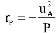
se puede linealizar la ecuación de estado en torno a un punto de funcionamiento en forma de una tensión de salida ua y de una corriente de carga iL. Este modelo de carga en forma de carga de potencia constante CPL también se puede incorporar al modelo del emulador de batería 1, como se describe la patente internacional núm. WO 2013/174967 A1. En una realización más sencilla, el modelo de carga se podría formar simplemente a partir de la capacitancia de entrada del objeto de prueba 10. Esta capacitancia de entrada se puede medir, o conocer de manera sencilla. Sin embargo, puede que el modelo de carga no esté incorporado en absoluto en el modelo del emulador de batería 1.The equation of state can be linearized around an operating point in the form of an output voltage ua and a load current iL. This charging model in the form of a constant power charge CPL can also be incorporated into the battery emulator model 1, as described in international patent no. WO 2013/174967 A1. In a simpler embodiment, the charge model could be formed simply from the input capacitance of the test object 10. This input capacitance can be measured, or known from simple way. However, the charging model may not be built into the battery emulator 1 model at all.
Con la estructura del modelo mostrado en la figura 3, se puede construir la siguiente ecuación de estado como modelo del emulador de batería 1, en donde la capacitancia de entrada CP del objeto de prueba 10 se utiliza como modelo de carga, pero esto también podría omitirse por razones de simplicidad. Con el vector de estado xc = [i1 v1 i2 ua]t , medido en la operación, se obtiene el modelo espacial de estadoWith the structure of the model shown in figure 3, the following equation of state can be constructed as the model of the battery emulator 1, where the input capacitance CP of the test object 10 is used as the charging model, but this could also omitted for the sake of simplicity. With the state vector xc = [i1 v1 i2 ua ] t, measured in the operation, the spatial state model is obtained

Donde RLF denota la resistencia parásita de la inductancia de filtro LF y RLL denota la resistencia de línea de la línea 4, que se conoce o se puede medir. La magnitud de ajuste s viene dada por s = d-uo, con el ciclo de trabajo d de la modulación de duración de pulsos PWM. En el caso de un convertidor de CC multifásico 3, las inductancias de filtro individuales de cada fase se combinan para formar una inductancia de filtro Lf y las corrientes de las fases individuales se suman para formar una corriente de choque común ii. Por supuesto, si no se miden directamente, las magnitudes del vector de estado Xc también podrían ser estimadas por un observador técnico de la regulación. Where RLF denotes the parasitic resistance of the filter inductance LF and RLL denotes the line resistance of line 4, which is known or measurable. The control variable s is given by s = d-uo, with the duty cycle d of the PWM pulse width modulation. In the case of a multiphase DC converter 3, the individual filter inductances of each phase combine to form a filter inductance L f and the currents of the individual phases add together to form a common shock current ii. Of course, if not measured directly, the magnitudes of the state vector Xc could also be estimated by a technical observer of regulation.
Con el modelo de carga descrito para una carga de potencia constante CPL, este modelo espacial de estado se puede ampliar insertando la resistencia de compensación diferencial rP. With the load model described for a constant power load CPL, this spatial state model can be expanded by inserting the differential compensation resistor rP.
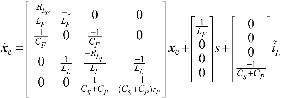
Esta ecuación de estado se aplica a un punto de funcionamiento concreto del emulador de batería 1. Por lo tanto, el modelo se debe adaptar al punto de funcionamiento particular durante la operación. La ventaja de utilizar este modelo de carga es que solo se necesitan dos parámetros adicionales para este fin, que son fáciles de determinar. This equation of state applies to a particular operating point of Battery Emulator 1. Therefore, the model must be adapted to the particular operating point during operation. The advantage of using this load model is that only two additional parameters are needed for this purpose, which are easy to determine.
Para la regulación, el modelo espacial de estado en tiempo continuo se convierte de forma conocida en un modelo espacial de estado en tiempo discreto. El muestreo A se indica en la figura 3 y se puede realizar, por ejemplo, con una frecuencia de 16 kHz.For regulation, the continuous-time state spatial model is known to be converted into a discrete-time state spatial model. Sampling A is indicated in Figure 3 and can be performed, for example, with a frequency of 16 kHz.
El modelo del emulador de batería 1 con los parámetros del modelo se puede crear de antemano y considerarse conocido. El modelo de carga, por otra parte, puede cambiar en función de la carga eléctrica conectada y a menudo no se conoce. En este caso, el enfoque puede consistir en identificar los parámetros del modelo de carga mediante métodos de identificación automatizados conocidos en sí mismos.The battery emulator model 1 with the model parameters can be created in advance and considered known. The load model, on the other hand, can change depending on the connected electrical load and is often not known. In this case, the approach may be to identify the parameters of the load model using automated identification methods known per se.
Para ello, el dispositivo de prueba compuesto por el emulador de batería 1 y el objeto de prueba 10 puede ser excitado con una secuencia de excitación en forma de variación temporal predeterminada de la tensión de salida ua . Si la capacitancia de entrada CP del objeto de prueba 10 es menor que la capacitancia del condensador de respaldo Cs , la identificación se puede realizar con el elemento de prueba 10 desconectado. Si la capacitancia de entrada Cp del objeto de prueba es igual o mayor que la capacitancia del condensador de respaldo CS, el objeto de prueba 10 afecta significativamente la respuesta dinámica y se debe conectar para la identificación de parámetros. Sin embargo, la identificación de los parámetros se puede realizar sin carga y con el objeto de prueba 10 desconectado. La reacción del dispositivo de prueba se mide y se registra en términos de las variables medidas (de acuerdo con la estructura del modelo). A continuación, se excita el modelo del emulador de batería 1 (filtro de salida 8 línea 4 caja de conexiones 7 con condensador de respaldo Cs + objeto de prueba 10, si procede) con la misma secuencia de excitación y se simula y se registra la salida del modelo. La diferencia entre las magnitudes/señales medidas y las magnitudes/señales simuladas se utiliza entonces como error para minimizar este error en una optimización, por ejemplo como la suma de los cuadrados del error, en función de los parámetros del modelo. Esta identificación del modelo de carga se puede realizar, por ejemplo, antes de cada prueba, o una vez para cada objeto de prueba 10. For this, the test device composed of the battery emulator 1 and the test object 10 can be excited with an excitation sequence in the form of a predetermined time variation of the output voltage u a . If the input capacitance C P of test object 10 is less than the capacitance of backing capacitor C s , identification can be made with test element 10 disconnected. If the input capacitance C p of the test object is equal to or greater than the capacitance of the backup capacitor C S , the test object 10 significantly affects the dynamic response and must be connected for parameter identification. However, the identification of the parameters can be performed without load and with the test object 10 disconnected. The reaction of the test device is measured and recorded in terms of the measured variables (according to the structure of the model). Next, battery emulator model 1 (output filter 8 line 4 junction box 7 with backup capacitor C s + test object 10, if applicable) is driven with the same drive sequence and simulated and recorded the output of the model. The difference between the measured quantities / signals and the simulated quantities / signals is then used as an error to minimize this error in an optimization, for example as the sum of the squares of the error, as a function of the model parameters. This identification of the load model can be done, for example, before each test, or once for each test object 10.
Claims (7)
Applications Claiming Priority (2)
| Application Number | Priority Date | Filing Date | Title |
|---|---|---|---|
| ATA50676/2015A AT517652B1 (en) | 2015-07-28 | 2015-07-28 | Battery emulator and method for regulating the battery emulator |
| PCT/EP2016/067485 WO2017016994A1 (en) | 2015-07-28 | 2016-07-22 | Battery emulator, and method for controlling the battery emulator |
Publications (1)
| Publication Number | Publication Date |
|---|---|
| ES2859503T3 true ES2859503T3 (en) | 2021-10-04 |
Family
ID=56550868
Family Applications (1)
| Application Number | Title | Priority Date | Filing Date |
|---|---|---|---|
| ES16744355T Active ES2859503T3 (en) | 2015-07-28 | 2016-07-22 | Battery emulator and method to regulate the battery emulator |
Country Status (6)
| Country | Link |
|---|---|
| US (1) | US10871791B2 (en) |
| EP (1) | EP3328677B1 (en) |
| CN (1) | CN107921875B (en) |
| AT (1) | AT517652B1 (en) |
| ES (1) | ES2859503T3 (en) |
| WO (1) | WO2017016994A1 (en) |
Families Citing this family (1)
| Publication number | Priority date | Publication date | Assignee | Title |
|---|---|---|---|---|
| AT520392B1 (en) * | 2017-09-04 | 2020-08-15 | Avl List Gmbh | Energy storage emulator and method for emulating an energy storage |
Family Cites Families (12)
| Publication number | Priority date | Publication date | Assignee | Title |
|---|---|---|---|---|
| JP3402117B2 (en) * | 1997-04-25 | 2003-04-28 | オムロン株式会社 | Inverter |
| CN2791657Y (en) * | 2004-10-29 | 2006-06-28 | 山东大学 | Electric load general simulation device |
| DE102007027049A1 (en) * | 2007-06-12 | 2008-12-18 | Robert Bosch Gmbh | Switched voltage converter with predictive model-based transistor control |
| DE102009034555B4 (en) * | 2009-07-23 | 2020-08-13 | Dr. Ing. H.C. F. Porsche Aktiengesellschaft | Test bench and test procedure for dynamic testing of a test object with a hybrid drive |
| JP2011158354A (en) * | 2010-02-01 | 2011-08-18 | Sinfonia Technology Co Ltd | Battery simulator |
| US8818141B1 (en) * | 2010-06-25 | 2014-08-26 | University Of Washington | Transmission line driven slot waveguide mach-zehnder interferometers |
| AT510998B1 (en) * | 2012-03-16 | 2014-08-15 | Avl List Gmbh | Test and test bench system for at least partially electrified engines |
| CN103424582B (en) * | 2012-05-17 | 2017-12-19 | 富泰华工业(深圳)有限公司 | Battery analogue circuit |
| AT511270B1 (en) * | 2012-05-24 | 2015-07-15 | Avl List Gmbh | Method and device for testing electric energy storage systems for driving vehicles |
| AT511520B1 (en) * | 2012-05-24 | 2017-06-15 | Avl List Gmbh | Method and device for testing the drive train of at least partially electrically operated vehicles |
| US10270251B1 (en) * | 2012-10-24 | 2019-04-23 | National Technology & Engineering Solutions Of Sandia, Llc | Emulator apparatus for microgrid testing and design |
| AT513776B1 (en) * | 2014-04-08 | 2015-09-15 | Avl List Gmbh | Method and controller for model-predictive control of a multiphase DC / DC converter |
-
2015
- 2015-07-28 AT ATA50676/2015A patent/AT517652B1/en active
-
2016
- 2016-07-22 WO PCT/EP2016/067485 patent/WO2017016994A1/en not_active Ceased
- 2016-07-22 EP EP16744355.5A patent/EP3328677B1/en active Active
- 2016-07-22 US US15/747,040 patent/US10871791B2/en active Active
- 2016-07-22 ES ES16744355T patent/ES2859503T3/en active Active
- 2016-07-22 CN CN201680043803.2A patent/CN107921875B/en active Active
Also Published As
| Publication number | Publication date |
|---|---|
| CN107921875A (en) | 2018-04-17 |
| AT517652B1 (en) | 2018-04-15 |
| WO2017016994A1 (en) | 2017-02-02 |
| US10871791B2 (en) | 2020-12-22 |
| AT517652A1 (en) | 2017-03-15 |
| EP3328677B1 (en) | 2020-12-16 |
| EP3328677A1 (en) | 2018-06-06 |
| CN107921875B (en) | 2020-11-06 |
| US20190011941A1 (en) | 2019-01-10 |
Similar Documents
| Publication | Publication Date | Title |
|---|---|---|
| JP7333531B2 (en) | Electrical architecture for electrochemical impedance spectroscopy | |
| CN108012538B (en) | hybrid energy storage | |
| ES2912888T3 (en) | Electric Vehicle Power Distribution System | |
| US12117499B2 (en) | Battery management apparatus, battery management method, and battery energy storage system | |
| US10124789B2 (en) | In-range current sensor fault detection | |
| JP6101714B2 (en) | Battery control device, battery system | |
| US9472977B2 (en) | Battery cell state of charge estimation | |
| US8872471B2 (en) | Variable output current battery charger and method of operating same | |
| CN114335812B (en) | Structure for self-heating of battery | |
| US20160103185A1 (en) | Electrified vehicle battery state-of-charge monitoring with aging compensation | |
| US20150326038A1 (en) | System and method for battery power management | |
| KR101707150B1 (en) | Apparatus for cell balancing of battery pack and method thereof | |
| US20160216336A1 (en) | Secondary battery charge status estimation device and secondary battery charge status estimation method | |
| WO2014122721A1 (en) | Cell control device | |
| EP2720054A1 (en) | Battery control device and battery system | |
| CN105391107A (en) | Method for battery state of charge estimation | |
| US20190043674A1 (en) | Electric power storage apparatus | |
| CN116660772A (en) | Impedance Estimation of Power Supply Via Motor Inverter Circuit | |
| Högerl et al. | Battery emulation for battery modular multilevel management (bm3) converters and reconfigurable batteries with series, parallel and bypass function | |
| US9139103B2 (en) | Battery cell capacity balancing system and method | |
| ES2859503T3 (en) | Battery emulator and method to regulate the battery emulator | |
| US8793042B2 (en) | Method and system for charging a vehicle battery | |
| US20140095088A1 (en) | Systems and methods for characterization of energy storage devices | |
| US12429527B2 (en) | System and method for online electrochemical impedance spectroscopy measurement in a battery | |
| JP4764324B2 (en) | Energy equalization equipment |