ES2871573T3 - Procedure and device for detection and characterization of a reflective element on an object - Google Patents
Procedure and device for detection and characterization of a reflective element on an object Download PDFInfo
- Publication number
- ES2871573T3 ES2871573T3 ES17780437T ES17780437T ES2871573T3 ES 2871573 T3 ES2871573 T3 ES 2871573T3 ES 17780437 T ES17780437 T ES 17780437T ES 17780437 T ES17780437 T ES 17780437T ES 2871573 T3 ES2871573 T3 ES 2871573T3
- Authority
- ES
- Spain
- Prior art keywords
- reconstruction
- ultrasonic
- mode
- wave
- reflections
- Prior art date
- Legal status (The legal status is an assumption and is not a legal conclusion. Google has not performed a legal analysis and makes no representation as to the accuracy of the status listed.)
- Active
Links
- 238000000034 method Methods 0.000 title claims abstract description 45
- 238000001514 detection method Methods 0.000 title claims abstract description 29
- 238000012512 characterization method Methods 0.000 title description 9
- 230000007547 defect Effects 0.000 claims description 54
- 238000004364 calculation method Methods 0.000 claims description 9
- 238000012545 processing Methods 0.000 claims description 7
- 230000003993 interaction Effects 0.000 claims description 4
- 238000003384 imaging method Methods 0.000 description 8
- 238000013507 mapping Methods 0.000 description 7
- 239000011159 matrix material Substances 0.000 description 6
- 238000002592 echocardiography Methods 0.000 description 5
- 239000000463 material Substances 0.000 description 5
- 238000004422 calculation algorithm Methods 0.000 description 4
- 230000001066 destructive effect Effects 0.000 description 4
- 238000010276 construction Methods 0.000 description 3
- 239000000047 product Substances 0.000 description 3
- 238000013459 approach Methods 0.000 description 2
- 230000005540 biological transmission Effects 0.000 description 2
- 230000008878 coupling Effects 0.000 description 2
- 238000010168 coupling process Methods 0.000 description 2
- 238000005859 coupling reaction Methods 0.000 description 2
- 238000011156 evaluation Methods 0.000 description 2
- 238000007689 inspection Methods 0.000 description 2
- 239000007788 liquid Substances 0.000 description 2
- 230000000704 physical effect Effects 0.000 description 2
- 238000004088 simulation Methods 0.000 description 2
- 230000007847 structural defect Effects 0.000 description 2
- 238000012285 ultrasound imaging Methods 0.000 description 2
- 238000012800 visualization Methods 0.000 description 2
- 241000726103 Atta Species 0.000 description 1
- OOFLZRMKTMLSMH-UHFFFAOYSA-N H4atta Chemical compound OC(=O)CN(CC(O)=O)CC1=CC=CC(C=2N=C(C=C(C=2)C=2C3=CC=CC=C3C=C3C=CC=CC3=2)C=2N=C(CN(CC(O)=O)CC(O)=O)C=CC=2)=N1 OOFLZRMKTMLSMH-UHFFFAOYSA-N 0.000 description 1
- 229910000831 Steel Inorganic materials 0.000 description 1
- 238000004458 analytical method Methods 0.000 description 1
- 238000003491 array Methods 0.000 description 1
- 230000000712 assembly Effects 0.000 description 1
- 238000000429 assembly Methods 0.000 description 1
- 230000001427 coherent effect Effects 0.000 description 1
- 230000000295 complement effect Effects 0.000 description 1
- 230000003111 delayed effect Effects 0.000 description 1
- 230000000694 effects Effects 0.000 description 1
- 230000002349 favourable effect Effects 0.000 description 1
- 238000007654 immersion Methods 0.000 description 1
- 230000004807 localization Effects 0.000 description 1
- 238000012544 monitoring process Methods 0.000 description 1
- 239000003348 petrochemical agent Substances 0.000 description 1
- 230000010287 polarization Effects 0.000 description 1
- 238000012805 post-processing Methods 0.000 description 1
- 230000001902 propagating effect Effects 0.000 description 1
- 238000012552 review Methods 0.000 description 1
- 239000010959 steel Substances 0.000 description 1
- 239000013589 supplement Substances 0.000 description 1
- 230000002123 temporal effect Effects 0.000 description 1
- XLYOFNOQVPJJNP-UHFFFAOYSA-N water Substances O XLYOFNOQVPJJNP-UHFFFAOYSA-N 0.000 description 1
Classifications
-
- G—PHYSICS
- G01—MEASURING; TESTING
- G01H—MEASUREMENT OF MECHANICAL VIBRATIONS OR ULTRASONIC, SONIC OR INFRASONIC WAVES
- G01H5/00—Measuring propagation velocity of ultrasonic, sonic or infrasonic waves, e.g. of pressure waves
-
- G—PHYSICS
- G01—MEASURING; TESTING
- G01N—INVESTIGATING OR ANALYSING MATERIALS BY DETERMINING THEIR CHEMICAL OR PHYSICAL PROPERTIES
- G01N29/00—Investigating or analysing materials by the use of ultrasonic, sonic or infrasonic waves; Visualisation of the interior of objects by transmitting ultrasonic or sonic waves through the object
- G01N29/44—Processing the detected response signal, e.g. electronic circuits specially adapted therefor
- G01N29/4409—Processing the detected response signal, e.g. electronic circuits specially adapted therefor by comparison
-
- G—PHYSICS
- G01—MEASURING; TESTING
- G01N—INVESTIGATING OR ANALYSING MATERIALS BY DETERMINING THEIR CHEMICAL OR PHYSICAL PROPERTIES
- G01N29/00—Investigating or analysing materials by the use of ultrasonic, sonic or infrasonic waves; Visualisation of the interior of objects by transmitting ultrasonic or sonic waves through the object
- G01N29/04—Analysing solids
- G01N29/043—Analysing solids in the interior, e.g. by shear waves
-
- G—PHYSICS
- G01—MEASURING; TESTING
- G01N—INVESTIGATING OR ANALYSING MATERIALS BY DETERMINING THEIR CHEMICAL OR PHYSICAL PROPERTIES
- G01N29/00—Investigating or analysing materials by the use of ultrasonic, sonic or infrasonic waves; Visualisation of the interior of objects by transmitting ultrasonic or sonic waves through the object
- G01N29/04—Analysing solids
- G01N29/06—Visualisation of the interior, e.g. acoustic microscopy
- G01N29/0654—Imaging
-
- G—PHYSICS
- G01—MEASURING; TESTING
- G01N—INVESTIGATING OR ANALYSING MATERIALS BY DETERMINING THEIR CHEMICAL OR PHYSICAL PROPERTIES
- G01N29/00—Investigating or analysing materials by the use of ultrasonic, sonic or infrasonic waves; Visualisation of the interior of objects by transmitting ultrasonic or sonic waves through the object
- G01N29/04—Analysing solids
- G01N29/06—Visualisation of the interior, e.g. acoustic microscopy
- G01N29/0654—Imaging
- G01N29/0672—Imaging by acoustic tomography
-
- G—PHYSICS
- G01—MEASURING; TESTING
- G01N—INVESTIGATING OR ANALYSING MATERIALS BY DETERMINING THEIR CHEMICAL OR PHYSICAL PROPERTIES
- G01N29/00—Investigating or analysing materials by the use of ultrasonic, sonic or infrasonic waves; Visualisation of the interior of objects by transmitting ultrasonic or sonic waves through the object
- G01N29/04—Analysing solids
- G01N29/06—Visualisation of the interior, e.g. acoustic microscopy
- G01N29/0654—Imaging
- G01N29/069—Defect imaging, localisation and sizing using, e.g. time of flight diffraction [TOFD], synthetic aperture focusing technique [SAFT], Amplituden-Laufzeit-Ortskurven [ALOK] technique
-
- G—PHYSICS
- G01—MEASURING; TESTING
- G01N—INVESTIGATING OR ANALYSING MATERIALS BY DETERMINING THEIR CHEMICAL OR PHYSICAL PROPERTIES
- G01N29/00—Investigating or analysing materials by the use of ultrasonic, sonic or infrasonic waves; Visualisation of the interior of objects by transmitting ultrasonic or sonic waves through the object
- G01N29/04—Analysing solids
- G01N29/07—Analysing solids by measuring propagation velocity or propagation time of acoustic waves
-
- G—PHYSICS
- G01—MEASURING; TESTING
- G01N—INVESTIGATING OR ANALYSING MATERIALS BY DETERMINING THEIR CHEMICAL OR PHYSICAL PROPERTIES
- G01N29/00—Investigating or analysing materials by the use of ultrasonic, sonic or infrasonic waves; Visualisation of the interior of objects by transmitting ultrasonic or sonic waves through the object
- G01N29/22—Details, e.g. general constructional or apparatus details
- G01N29/26—Arrangements for orientation or scanning by relative movement of the head and the sensor
- G01N29/262—Arrangements for orientation or scanning by relative movement of the head and the sensor by electronic orientation or focusing, e.g. with phased arrays
-
- G—PHYSICS
- G01—MEASURING; TESTING
- G01N—INVESTIGATING OR ANALYSING MATERIALS BY DETERMINING THEIR CHEMICAL OR PHYSICAL PROPERTIES
- G01N29/00—Investigating or analysing materials by the use of ultrasonic, sonic or infrasonic waves; Visualisation of the interior of objects by transmitting ultrasonic or sonic waves through the object
- G01N29/44—Processing the detected response signal, e.g. electronic circuits specially adapted therefor
- G01N29/4445—Classification of defects
-
- G—PHYSICS
- G01—MEASURING; TESTING
- G01S—RADIO DIRECTION-FINDING; RADIO NAVIGATION; DETERMINING DISTANCE OR VELOCITY BY USE OF RADIO WAVES; LOCATING OR PRESENCE-DETECTING BY USE OF THE REFLECTION OR RERADIATION OF RADIO WAVES; ANALOGOUS ARRANGEMENTS USING OTHER WAVES
- G01S15/00—Systems using the reflection or reradiation of acoustic waves, e.g. sonar systems
- G01S15/88—Sonar systems specially adapted for specific applications
- G01S15/89—Sonar systems specially adapted for specific applications for mapping or imaging
- G01S15/8906—Short-range imaging systems; Acoustic microscope systems using pulse-echo techniques
- G01S15/8909—Short-range imaging systems; Acoustic microscope systems using pulse-echo techniques using a static transducer configuration
- G01S15/8915—Short-range imaging systems; Acoustic microscope systems using pulse-echo techniques using a static transducer configuration using a transducer array
-
- G—PHYSICS
- G01—MEASURING; TESTING
- G01S—RADIO DIRECTION-FINDING; RADIO NAVIGATION; DETERMINING DISTANCE OR VELOCITY BY USE OF RADIO WAVES; LOCATING OR PRESENCE-DETECTING BY USE OF THE REFLECTION OR RERADIATION OF RADIO WAVES; ANALOGOUS ARRANGEMENTS USING OTHER WAVES
- G01S15/00—Systems using the reflection or reradiation of acoustic waves, e.g. sonar systems
- G01S15/88—Sonar systems specially adapted for specific applications
- G01S15/89—Sonar systems specially adapted for specific applications for mapping or imaging
- G01S15/8906—Short-range imaging systems; Acoustic microscope systems using pulse-echo techniques
- G01S15/8977—Short-range imaging systems; Acoustic microscope systems using pulse-echo techniques using special techniques for image reconstruction, e.g. FFT, geometrical transformations, spatial deconvolution, time deconvolution
-
- G—PHYSICS
- G01—MEASURING; TESTING
- G01S—RADIO DIRECTION-FINDING; RADIO NAVIGATION; DETERMINING DISTANCE OR VELOCITY BY USE OF RADIO WAVES; LOCATING OR PRESENCE-DETECTING BY USE OF THE REFLECTION OR RERADIATION OF RADIO WAVES; ANALOGOUS ARRANGEMENTS USING OTHER WAVES
- G01S15/00—Systems using the reflection or reradiation of acoustic waves, e.g. sonar systems
- G01S15/88—Sonar systems specially adapted for specific applications
- G01S15/89—Sonar systems specially adapted for specific applications for mapping or imaging
- G01S15/8906—Short-range imaging systems; Acoustic microscope systems using pulse-echo techniques
- G01S15/8997—Short-range imaging systems; Acoustic microscope systems using pulse-echo techniques using synthetic aperture techniques
-
- G—PHYSICS
- G01—MEASURING; TESTING
- G01N—INVESTIGATING OR ANALYSING MATERIALS BY DETERMINING THEIR CHEMICAL OR PHYSICAL PROPERTIES
- G01N2291/00—Indexing codes associated with group G01N29/00
- G01N2291/01—Indexing codes associated with the measuring variable
- G01N2291/011—Velocity or travel time
-
- G—PHYSICS
- G01—MEASURING; TESTING
- G01N—INVESTIGATING OR ANALYSING MATERIALS BY DETERMINING THEIR CHEMICAL OR PHYSICAL PROPERTIES
- G01N2291/00—Indexing codes associated with group G01N29/00
- G01N2291/02—Indexing codes associated with the analysed material
- G01N2291/023—Solids
-
- G—PHYSICS
- G01—MEASURING; TESTING
- G01N—INVESTIGATING OR ANALYSING MATERIALS BY DETERMINING THEIR CHEMICAL OR PHYSICAL PROPERTIES
- G01N2291/00—Indexing codes associated with group G01N29/00
- G01N2291/04—Wave modes and trajectories
- G01N2291/044—Internal reflections (echoes), e.g. on walls or defects
-
- G—PHYSICS
- G01—MEASURING; TESTING
- G01N—INVESTIGATING OR ANALYSING MATERIALS BY DETERMINING THEIR CHEMICAL OR PHYSICAL PROPERTIES
- G01N2291/00—Indexing codes associated with group G01N29/00
- G01N2291/04—Wave modes and trajectories
- G01N2291/056—Angular incidence, angular propagation
-
- G—PHYSICS
- G01—MEASURING; TESTING
- G01N—INVESTIGATING OR ANALYSING MATERIALS BY DETERMINING THEIR CHEMICAL OR PHYSICAL PROPERTIES
- G01N2291/00—Indexing codes associated with group G01N29/00
- G01N2291/10—Number of transducers
- G01N2291/106—Number of transducers one or more transducer arrays
Landscapes
- Physics & Mathematics (AREA)
- General Physics & Mathematics (AREA)
- Acoustics & Sound (AREA)
- Engineering & Computer Science (AREA)
- Radar, Positioning & Navigation (AREA)
- Remote Sensing (AREA)
- Life Sciences & Earth Sciences (AREA)
- General Health & Medical Sciences (AREA)
- Chemical & Material Sciences (AREA)
- Immunology (AREA)
- Pathology (AREA)
- Analytical Chemistry (AREA)
- Health & Medical Sciences (AREA)
- Biochemistry (AREA)
- Computer Networks & Wireless Communication (AREA)
- Signal Processing (AREA)
- Investigating Or Analyzing Materials By The Use Of Ultrasonic Waves (AREA)
- Measurement Of Velocity Or Position Using Acoustic Or Ultrasonic Waves (AREA)
Abstract
Procedimiento para determinar al menos un modo de reconstrucción m de un objeto reflector que presenta una parte capaz de generar reflexiones especulares de ondas ultrasónicas, dentro de un volumen dado Zr, caracterizado porque incluye al menos las siguientes etapas: - para cada punto P del volumen dado Zr, determinar un valor de campo ultrasónico **(Ver fórmula)** para N pares (i, j) de transmisores-receptores y para un modo de detección m, - calcular un número de reflexiones de la onda **(Ver fórmula)** donde **(Ver fórmula)** con **(Ver fórmula)** la normal formada por la dirección "ida" d*i y la dirección "vuelta" d*j de la onda ultrasónica transmitida y reflejada por el elemento reflector, - calcular el valor de energía Em(P, n*) para cada punto P de la zona Zr, con n* la normal al elemento reflector y para varios modos de detección m, sumando sobre los N pares de transmisores-receptores, (i, j), el producto del valor de campo ultrasónico por el número de reflexiones de la onda: con **(Ver fórmula)** - comparar dicho o dichos valores de energías Em(P, ) obtenidos con un criterio dado y a partir del resultado obtenido seleccionar al menos un modo de reconstrucción m a usar para detectar y caracterizar el elemento reflector.Method for determining at least one reconstruction mode m of a reflective object that has a part capable of generating specular reflections of ultrasonic waves, within a given volume Zr, characterized in that it includes at least the following steps: - for each point P of the volume given Zr, determine an ultrasonic field value **(See formula)** for N pairs (i, j) of transmitter-receivers and for a detection mode m, - calculate a number of reflections of the wave **(See formula)** where **(See formula)** with **(See formula)** the normal formed by the "go" direction d*i and the "return" direction d*j of the ultrasonic wave transmitted and reflected by the reflector element, - calculate the energy value Em(P, n*) for each point P of the zone Zr, with n* the normal to the reflector element and for various detection modes m, summing over the N pairs of transmitters- receivers, (i, j), the product of the value of the ultrasonic field by the number of reflections of the wave: c on **(See formula)** - compare said energy value(s) Em(P, ) obtained with a given criterion and from the result obtained select at least one reconstruction mode m to be used to detect and characterize the reflector element.
Description
DESCRIPCIÓNDESCRIPTION
Procedimiento y dispositivo de detección y caracterización de un elemento reflector en un objetoProcedure and device for detection and characterization of a reflective element on an object
La invención se refiere a un procedimiento y a un dispositivo que permiten definir uno o varios modos de reconstrucción para detectar y caracterizar unos defectos, en concreto, por imagenología y por enfoque sintético multimodal.The invention relates to a method and a device that make it possible to define one or more reconstruction modes to detect and characterize defects, specifically, by imaging and by multimodal synthetic approach.
También encuentra su aplicación en cualquier campo donde se busque detectar y caracterizar unos elementos capaces de reflejar una onda ultrasónica, estando los elementos ocultos en un objeto y pudiendo ser un defecto de estructura, una dislocación, una grieta, etc.It also finds its application in any field where it is sought to detect and characterize elements capable of reflecting an ultrasonic wave, the elements being hidden in an object and may be a structural defect, a dislocation, a crack, etc.
También se puede implementar para caracterizar el perfil de una pieza.It can also be implemented to characterize the profile of a part.
En el campo del control no destructivo, en la actualidad, están disponibles unas numerosas técnicas de imagenología ultrasónicas. Estas técnicas representan una herramienta mayor para las aplicaciones de control no destructivo de los materiales y de los ensamblajes en unos numerosos campos industriales pioneros, tales como la energía, la petroquímica, la siderurgia, los transportes. Permiten obtener una información de localización absoluta y unas descripciones cada vez más realistas de la morfología de los defectos de estructura.In the field of non-destructive monitoring, a number of ultrasonic imaging techniques are available today. These techniques represent a major tool for non-destructive control of materials and assemblies applications in a number of pioneering industrial fields, such as energy, petrochemicals, steel, and transportation. They make it possible to obtain absolute location information and increasingly realistic descriptions of the morphology of structural defects.
Los métodos de caracterización están estrechamente relacionados con la imagenología ultrasónica. En este sentido, las técnicas de multielementos conocidas bajo la designación anglosajona "Phased Array" han mejorado considerablemente las posibilidades de análisis.Characterization methods are closely related to ultrasonic imaging. In this sense, the multi-element techniques known under the Anglo-Saxon designation "Phased Array" have considerably improved the possibilities of analysis.
Los métodos de enfoque sintéticos, tales como los métodos de enfoque total o TFM (abreviatura anglosajona de Total Focussing Method) proponen, por ejemplo, una imagenología ecográfica realista del material inspeccionado, explotando una instrumentación de multielemento convencional. Las imágenes TFM aportan una resolución óptima en toda la vista obtenida. Por construcción, estas imágenes TFM ofrecen como ventajas que son poco sensibles a los efectos de sombreado y a los rebotes múltiples. Según los modos de propagación y la polaridad de las ondas seleccionadas, la imagenología TFM permite dibujar unos defectos de volumen o unos defectos planos verticales. Esta representación realista aporta una ventaja importante para la caracterización de los defectos, en particular, para unas grietas. Por lo tanto, las imágenes TFM son más fáciles de analizar; presentan menos riesgos de interpretación errónea y permiten contemplar unos controles más rápidos por unos operarios menos especializados.Synthetic focusing methods, such as Total Focussing Method or TFM (Total Focussing Method) propose, for example, a realistic ultrasound imaging of the inspected material, exploiting conventional multi-element instrumentation. TFM images provide optimal resolution throughout the view obtained. By construction, these TFM images offer the advantages that they are not very sensitive to shading effects and multiple bounces. Depending on the propagation modes and the polarity of the selected waves, TFM imaging allows the drawing of volume defects or vertical plane defects. This realistic representation provides an important advantage for the characterization of defects, in particular for cracks. Therefore, TFM images are easier to analyze; they present less risk of misinterpretation and allow for faster checks by less specialized operators.
Los métodos de enfoque sintético producen unas imágenes por el encadenamiento de dos etapas principales: una etapa de adquisición de las señales ultrasónicas y una etapa de construcción de las imágenes a partir de los datos anteriormente grabados. Estas dos etapas se pueden realizar de diferentes maneras expuestas a continuación. Uno de los principales tipos de grabaciones de las señales ultrasónicas sobre las que se aplicarán, a continuación, unos algoritmos de reconstrucción de los datos es la grabación de tipo FMC (Full Matrix Capture) o matriz de interelementos, tal como se describe en el documento de C. Holmes, B.W. Drinkwater, P.D. Wilcox, titulado "Post-Processing of the full matrix of ultrasonic transmit-receive array data for non-destructive evaluation", NDT&E international vol. 38, pp. 701-711, por ejemplo. En este caso, para un sensor ultrasónico constituido por varios elementos pilotables individualmente, este tipo de adquisición consiste en grabar un conjunto de M*N señales elementales, Sy(t), con 1<i<M y 1<j<N, donde M y N representan respectivamente los números de elementos usados en transmisión y en recepción. El índice i denota el número del elemento transmisor y el índice j el del elemento receptor. Se pueden usar otros métodos de adquisición de datos conocidos por el experto en la materia, tales como la transmisión de onda plana conocida bajo la abreviación anglosajona PWI (Plane Wave Imaging) o el método SAFT (abreviación anglosajona de Synthetic Aperture Focusing Technique).Synthetic focusing methods produce images by the chaining of two main stages: a stage of acquisition of the ultrasonic signals and a stage of construction of the images from the previously recorded data. These two stages can be carried out in different ways set out below. One of the main types of ultrasonic signal recordings on which data reconstruction algorithms will then be applied is FMC (Full Matrix Capture) or inter-element matrix recording, as described in the document. by C. Holmes, BW Drinkwater, PD Wilcox, entitled "Post-Processing of the full matrix of ultrasonic transmit-receive array data for non-destructive evaluation", NDT & E international vol. 38, pp. 701-711, for example. In this case, for an ultrasonic sensor made up of several individually controllable elements, this type of acquisition consists of recording a set of M * N elementary signals, Sy (t), with 1 <i <M and 1 <j <N, where M and N represent respectively the numbers of elements used in transmission and reception. The index i denotes the number of the transmitting element and the index j that of the receiving element. Other data acquisition methods known to those skilled in the art can be used, such as plane wave transmission known under the English abbreviation PWI (Plane Wave Imaging) or the SAFT method (Synthetic Aperture Focusing Technique).
Para la construcción de las imágenes, los métodos de enfoque sintético consisten en sumar, de forma coherente, las contribuciones extraídas de las señales ultrasónicas anteriormente grabadas en cada punto de la zona inspeccionada en un material. Estos métodos se pueden realizar en el campo temporal o frecuencial. De entre estos, el método TFM citado anteriormente constituye uno de estos principales métodos de imagenología. El algoritmo asociado consiste en sumar de forma coherente la amplitud de las señales recibidas para obtener unas interferencias constructivas y, de este modo, unos máximos de amplitud, en el sitio donde están efectivamente localizados los defectos en el origen de los ecos ultrasónicos detectados. Se apoya principalmente en la explotación de los tiempos de vuelo evaluados teóricamente a partir de modelos directos. Este algoritmo se puede resumir en tres etapas: 123For the construction of the images, the synthetic focusing methods consist of adding, in a coherent way, the contributions extracted from the ultrasonic signals previously recorded at each point of the inspected area in a material. These methods can be performed in the temporal or frequency field. Among these, the TFM method mentioned above constitutes one of these main imaging methods. The associated algorithm consists of coherently adding the amplitude of the received signals to obtain constructive interferences, and thus maximum amplitude, at the site where the defects at the origin of the detected ultrasonic echoes are actually located. It relies mainly on the exploitation of flight times theoretically evaluated from direct models. This algorithm can be summarized in three stages: 123
1. La definición de una zona de reconstrucción (posiciones, dimensiones y número de puntos de cálculo), 2. Para cada punto P de la zona de reconstrucción definida y para cada par transmisor-receptor (i,j), el cálculo del tiempo de vuelo teórico, correspondiendo Tj(P) al recorrido entre el transmisor i y el receptor j y que pasa por el punto P, 1. The definition of a reconstruction zone (positions, dimensions and number of calculation points), 2. For each point P of the defined reconstruction zone and for each transmitter-receiver pair ( i, j), the calculation of the time theoretical flight, Tj ( P) corresponding to the path between transmitter i and receiver j and passing through point P,
3. Para cada punto P de la zona, el sumatorio de las amplitudes extraídas de las señales Sj(t) en el tiempo t = Tj(P), lo que se puede escribir: 3. For each point P in the area, the sum of the amplitudes extracted from the signals Sj ( t) at time t = Tj ( P), which can be written:
M NM N
i ( r ) = t , í l s ÁTA p ')) <1>-í=l ;=1 i ( r) = t, í ls ATTA p ')) <1> -í = l; = 1
Este enfoque se puede realizar considerando, en la segunda etapa, varios modos de propagación (directo, ecos de esquina, ecos indirectos...) y varios tipos de ondas (longitudinales L o transversales T), tales como se describen, por ejemplo, en el documento de A. Fidahoussen, P. Calmon, M. Lambert, S. Paillard, S. Chatillon, "Imaging of defects in several complex configurations by simulation-helped processing of ultrasonic array data", Review of progress in QNDE, Vol. 29, pp. 847-854, 2010This approach can be carried out considering, in the second stage, several modes of propagation (direct, corner echoes, indirect echoes ...) and several types of waves (longitudinal L or transverse T), such as described, for example, in A. Fidahoussen, P. Calmon, M. Lambert, S. Paillard, S. Chatillon, "Imaging of defects in several complex configurations by simulation-helped processing of ultrasonic array data", Review of progress in QNDE, Vol 29, pp. 847-854, 2010
S. Paillard y col: "New ultrasonic array imaging of crack-type defects based on simulation-helped processing", agosto de 2010, describe un método para generar una imagen de un defecto.S. Paillard et al: "New ultrasonic array imaging of crack-type defects based on simulation-helped processing", August 2010, describe a method to generate an image of a defect.
Las figuras 1a, 1b y 1c ilustran diferentes tipos de trayectos. Para el modo de reconstrucción directo, figura 1a, los recorridos involucrados corresponden a unos trayectos directos entre los diferentes elementos del sensor C y los puntos P de la zona de reconstrucción, es decir, sin rebote sobre el fondo de la pieza, como se ilustra en esta figura 1a. Para los modos de reconstrucción de ecos de esquina y de ecos indirectos, (figuras 1b y 1c), los trayectos tomados en cuenta para el cálculo de los tiempos de vuelo en la ecuación (1) pueden constar de una o varias reflexiones sobre el fondo de la pieza A en el transcurso del trayecto entre el elemento transmisor y el punto de la zona de reconstrucción y/o en el transcurso del trayecto entre el punto de reconstrucción y el elemento receptor. La polarización de la onda entre dos interacciones sucesivas, longitudinal o transversal se toma en cuenta, igualmente. Figures 1a, 1b and 1c illustrate different types of paths. For the direct reconstruction mode, figure 1a, the paths involved correspond to direct paths between the different elements of the sensor C and the points P of the reconstruction zone, that is, without rebounding on the bottom of the piece, as illustrated in this figure 1a. For the corner echo and indirect echo reconstruction modes (Figures 1b and 1c), the paths taken into account for the calculation of flight times in equation (1) can consist of one or more reflections on the bottom. of part A in the course of the path between the transmitting element and the point of the reconstruction zone and / or in the course of the path between the reconstruction point and the receiving element. The polarization of the wave between two successive interactions, longitudinal or transverse, is also taken into account.
El hecho de que cada reconstrucción TFM esté asociada a un modo de propagación (directo, eco de esquina, rebotes múltiples en la pieza...), así como la polaridad de las ondas ultrasónicas (longitudinal o transversal), da lugar a un número importante de imágenes, de las que cada una puede llevar una información diferente y complementaria sobre la posición, sobre la naturaleza y sobre la geometría de los defectos buscados D.The fact that each TFM reconstruction is associated with a propagation mode (direct, corner echo, multiple rebounds on the part ...), as well as the polarity of the ultrasonic waves (longitudinal or transverse), gives rise to a number important imagery, each of which can carry different and complementary information on the position, nature and geometry of the defects sought D.
La pertinencia de una imagen asociada a un modo de propagación dado varía en función de la configuración de control considerada (sensor usado, geometría de la pieza inspeccionada, posición y orientación del defecto...). Esta pertinencia no es, por lo demás, necesariamente verdadera para todos los puntos de una misma zona de reconstrucción.The relevance of an image associated with a given propagation mode varies depending on the control configuration considered (sensor used, geometry of the part inspected, position and orientation of the defect ...). This relevance is not, moreover, necessarily true for all the points of the same reconstruction area.
La técnica anterior también describe un "contador de reflexiones", ilustrado en la figura 2. Para un defecto plano D de orientación conocida, este estimador consiste en contabilizar el número de pares de transmisores i y receptores j, para los que existe un trayecto que verifica la ley de Snell-Descartes (figura 3) según el modo de reconstrucción considerado. De este modo, para un modo de reconstr -u>cción m, suponiendo que cada punto P d —e» la zona de reconstrucción pertenezca a un defecto plano de normal n, el Contador de Reflexiones anotado Cm(P,n), está dado por:The prior art also describes a "reflection counter", illustrated in figure 2. For a plane D defect of known orientation, this estimator consists of counting the number of pairs of transmitters i and receivers j, for which there is a path that verifies the Snell-Descartes law (figure 3) according to the mode of reconstruction considered. Thus, for a reconstruction mode m, assuming that each point P d —e »the reconstruction zone belongs to a plane defect of normal n, the Recorded Reflection Counter Cm ( P, n), is given by:

dondewhere

la normal formada por las direcciones de ¡da d¡ y vuelta di de la onda,the normal formed by the directions of the wave,
i: índice elemento transmisor,i: transmitter element index,
j: índice elemento receptor, j: receiver element index,
N\ número de elementos transmisor-receptor que componen el traductor, N \ number of transmitter-receiver elements that make up the translator,
9j, el ángulo que forma la dirección de ¡da h a¡ con la normal ñ ü m para un modo de reconstrucción m y 9r, el ángulo - _»i r M ?m 9j, the angle formed by the direction of ¡da h a¡ with the normal ñ ü m for a reconstruction mode m and 9r, the angle - _ »i r M ? M
que forma la dirección de vuelta ar con la normal ü para un modo de reconstrucción m.which forms the return direction ar with the normal ü for a reconstruction mode m.
Se describe un método de reconstrucción ultrasónica, por ejemplo, en el capítulo 5.3.2 de la tesis titulada "Développement de méthodes de reconstruction ultrasonore pour la localisation et la caractérisation de défauts" defendida por Alex Fidahoussen el 21 de septiembre de 2012.An ultrasonic reconstruction method is described, for example, in chapter 5.3.2 of the thesis entitled "Développement de méthodes de reconstruction ultrasonore pour la localisation et la caractérisation de défauts" defended by Alex Fidahoussen on September 21, 2012.
En el siguiente ejemplo, figura 4, se considera un defecto plano D de orientación vertical, en un objeto A a inspeccionar, para una zona de reconstrucción dada Zr y para una reconstrucción en modo eco de esquina (esto es, con un rebote sobre el fondo del objeto) que no toma en cuenta más que unas ondas transversales T. La evaluación del Contador de Reflexión Cm(P,n) en cada punto P de esta zona de reconstrucción Zr permite constituir una cartografía (figura 5) cuyos valores están codificados según una paleta de colores representada en la figura por unas zonas de grises con matices. De este modo, para un modo de reconstrucción m, esta cartografía indica que en la zona Z1 (Amplitud = 0), no puede existir ningún trayecto especular entre un transmisor i, un defecto plano de orientación vertical y un receptor j. Este estimador aporta una información necesaria, pero no suficiente, para predecir completamente la pertinencia de un modo de reconstrucción para detectar un defecto plano de orientación conocida situado en la zona de reconstrucción. En efecto, el modo de reconstrucción no considera más que los trayectos geométricos y deben tomarse en cuenta, igualmente, otras consideraciones físicas.In the following example, figure 4, a vertically oriented plane defect D is considered, in an object A to be inspected, for a given reconstruction zone Zr and for a reconstruction in corner echo mode (that is, with a bounce on the background of the object) that only takes into account some transverse T waves. The evaluation of the Reflection Counter Cm ( P, n) at each point P of this reconstruction zone Zr allows to constitute a cartography (figure 5) whose values are coded according to a color palette represented in the figure by gray areas with shades. Thus, for a reconstruction mode m, this mapping indicates that in the zone Z1 (Amplitude = 0), there can be no specular path between a transmitter i, a vertically oriented plane defect and a receiver j. This estimator provides information that is necessary, but not sufficient, to fully predict the relevance of a reconstruction mode to detect a plane defect of known orientation located in the reconstruction zone. Indeed, the mode of reconstruction only considers geometric paths and other physical considerations must also be taken into account.
La solicitud de patente francesa FR 3029636 describe un procedimiento de imagenología por ultrasonidos que usa un transductor de multielemento y basado en la técnica de reconstrucción llamada "enfoque en cualesquiera puntos". French patent application FR 3029636 describes an ultrasound imaging procedure using a multi-element transducer and based on the reconstruction technique called "focus on any points".
Uno de los objetivos de la invención es proponer una herramienta que permita predecir, para una configuración del sistema de detección de defectos y un tipo de defectos buscados, el o los modos de reconstrucción m más pertinentes a usar para obtener una mejor visualización y caracterización de defectos presentes en una pieza. Más precisamente, para cada punto P perteneciente a una zona de reconstrucción Zr, esta herramienta permite estimar la capacidad de un modo de reconstrucción para poder detectar o no, los rasgos de un defecto plano a partir de ecos especulares cuyo recorrido verifica la ley de Snell-Descartes, tal como se describe en el documento https://fr.wikipedia.org/wiki/Lois de Snell-Descartes o, de manera más general, para cualquier objeto o elemento plano de orientación conocida y que refleja las ondas ultrasónicas.One of the objectives of the invention is to propose a tool that allows predicting, for a configuration of the defect detection system and a type of defects sought, the most pertinent reconstruction mode (s) to be used to obtain a better visualization and characterization of defects present in a part. More precisely, for each point P belonging to a reconstruction zone Zr, this tool allows estimating the capacity of a reconstruction mode to be able to detect or not the features of a plane defect from specular echoes whose path is verified by Snell's law. -Descartes, as described in the document https://fr.wikipedia.org/wiki/Lois de Snell-Descartes or, more generally, for any object or plane element of known orientation and that reflects ultrasonic waves.
El o los modos de reconstrucción seleccionados a partir de los resultados sobre la capacidad de un modo se usarán, entonces, en un sistema de detección y de caracterización de defectos.The reconstruction mode (s) selected from the results on the capacity of a mode will then be used in a defect detection and characterization system.
En concreto, la invención puede asimilarse a un estimador de ecos especulares para un modo de reconstrucción considerado. El estimador consiste, en concreto, en calcular, en cada punto de una zona de interés, la contribución unitaria de cada par transmisor-receptor (i, j) de un sensor de detección de un eco especular que proviene de un defecto plano de orientación predefinida. Este cálculo se puede realizar por medio de una herramienta de simulación de propagación de ondas elastodinámicas conocida por el experto en la materia.In particular, the invention can be assimilated to a specular echo estimator for a considered reconstruction mode. The estimator consists, specifically, in calculating, at each point of an area of interest, the unit contribution of each transmitter-receiver pair (i, j) of a sensor detecting a specular echo that comes from a plane orientation defect predefined. This calculation can be carried out by means of an elastodynamic wave propagation simulation tool known to the person skilled in the art.
El sumatorio de todas estas contribuciones (energía reflejada) en cada uno de los puntos de una zona de interés permite, entonces, predecir la amplitud de detección de un tipo de defecto por un eco especular. Una cartografía de estas amplitudes, análoga a la propuesta para el contador de reflexiones de la técnica anterior, pero más precisa, se puede realizar, de este modo y, a partir de esta cartografía, un operario podrá seleccionar uno o varios modos de reconstrucción para inspeccionar un objeto.The summation of all these contributions (reflected energy) at each of the points of an area of interest then makes it possible to predict the amplitude of detection of a type of defect by a specular echo. A mapping of these amplitudes, analogous to the one proposed for the reflection counter of the prior art, but more precise, can be carried out in this way and, from this mapping, an operator will be able to select one or more reconstruction modes for inspect an object.
La invención se refiere a un procedimiento para determinar al menos un modo de reconstrucción m de un objeto reflector que presenta una parte capaz de generar unas reflexiones especulares de ondas ultrasónicas, dentro de un volumen dado Zr, caracterizado porque incluye al menos las siguientes etapas:The invention relates to a method for determining at least one reconstruction mode m of a reflective object that has a part capable of generating specular reflections of ultrasonic waves, within a given volume Zr, characterized in that it includes at least the following steps:
• para cada punto P del volumen dado Zr, determinar un valor de campo ultrasónico A' y " ( ' P) ' para N pares (i, j) de transmisores-receptores y para un modo de detección m, • for each point P of the given volume Zr, determine an ultrasonic field value A ' y " ( ' P) ' for N pairs (i, j) of transceivers and for a detection mode m,
• calcular un número de reflexiones de la onda

con ñ vm{ v P) 7 la normal formada por la dirección "¡da" d¡ y la dirección "vuelta" dí de la onda ultrasónica transmitida y reflejada por el elemento reflector, with ñ v m { v P) 7 the normal formed by the direction "¡da" d¡ and the direction "turn" dí of the ultrasonic wave transmitted and reflected by the reflector element,
calcular el valor de energía Em(P,n) para cada punto P de la zona Zr, con n la normal al elemento reflector y para varios modos de detección m, sumando sobre los N pares de transmisores-receptores, (i, j), el producto del valor de campo ultrasónico por el número de reflexiones de la onda: concalculate the energy value Em ( P, n) for each point P in the zone Zr, with n the normal to the reflector element and for various detection modes m, adding over the N pairs of transmitter-receivers, (i, j) , the product of the ultrasonic field value by the number of reflections of the wave: with
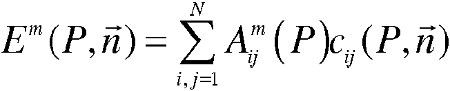
• comparar dicho o dichos valores de energía Em(P,n) obtenidos con un criterio dado y, a partir del resultado obtenido, seleccionar al menos un modo de reconstrucción m a usar para detectar y caracterizar el elemento reflector. • comparing said or said energy values Em ( P, n) obtained with a given criterion and, based on the obtained result, selecting at least one reconstruction mode m to be used to detect and characterize the reflector element.
Según una variante de realización, se determina el o los modos de reconstrucción m a usar eligiendo las energías Em(P,n) que son superiores a un valor umbral Es.According to a variant embodiment, the reconstruction mode (s) m to be used is determined by choosing the energies Em ( P, n) that are greater than a threshold value Es.
Según otra variante, el o los modos de reconstrucción m a usar se determinan limitando el número de modo de reconstrucción a un valor dado, que ofrece el mejor compromiso entre energía y dimensión de la zona de reconstrucción seleccionada.According to another variant, the reconstruction mode (s) to be used are determined by limiting the number of reconstruction mode to a given value, which offers the best compromise between energy and dimension of the selected reconstruction area.
El cálculo de la energía puede tomar en cuenta los coeficientes —> de reflexión R{n¡¡,n) correspondientes a la interacción de la onda con una superficie plana definida por la normal n a un punto P:The calculation of the energy can take into account the coefficients -> of reflection R {n¡¡, n) corresponding to the interaction of the wave with a plane surface defined by the normal n to a point P:

El valor de energía se determina, por ejemplo, teniendo en cuenta el número de reflexiones ponderado por una tolerancia arbitraria:The energy value is determined, for example, taking into account the number of reflections weighted by an arbitrary tolerance:

El elemento reflector a detectar puede ser un defecto plano dispuesto en una pieza a inspeccionar, tal como una falla, una muesca.The reflector element to be detected can be a flat defect arranged in a part to be inspected, such as a fault, a notch.
La invención también se refiere a un dispositivo para determinar al menos un modo de detección para un elemento reflector de ondas ultrasónicas, dentro de un volumen dado Zr y por reflexiones especulares y caracterizar uno o varios defectos en una pieza A que incluye al menos un transductor ultrasónico para transmitir y recibir unas ondas ultrasónicas y un dispositivo de procesamiento adaptado para usar el o los modos de reconstrucción obtenidos por la implementación de las siguientes etapas:The invention also relates to a device for determining at least one detection mode for an ultrasonic wave reflector element, within a given volume Zr and by specular reflections and characterizing one or more defects in a part A that includes at least one transducer ultrasonic to transmit and receive ultrasonic waves and a processing device adapted to use the reconstruction mode (s) obtained by implementing the following steps:
para cada punto P del volumen dado Zr, determinar un valor de campo ultrasónico 
C m( P , n ) = Y jC ; { P ,n ) C m ( P, n) = Y jC; {P, n)
calcular un número de reflexiones de la onda U=1 dondecalculate a number of reflections of the wave U = 1 where
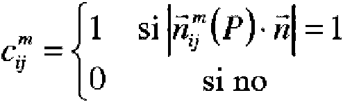
eon í l y (P) la normal formada por las direcciones "ida" d¡ y "vuelta" d; í de la onda ultrasónica transmitida y reflejada por el elemento reflector, eon í l and (P) the normal formed by the directions "go" d¡ and "return" d; í of the ultrasonic wave transmitted and reflected by the reflector element,
calcular el valor de energía Em(P,n) para cada punto P de la zona Zr, con n la normal al elemento reflector y para varios modos de detección m, sumando sobre los N pares de transmisores-receptores, (i, j), el producto del valor de campo ultrasónico por el número de reflexiones de la onda:calculate the energy value Em ( P, n) for each point P in the zone Zr, with n the normal to the reflector element and for various detection modes m, adding over the N pairs of transmitter-receivers, (i, j) , the product of the ultrasonic field value by the number of reflections of the wave:
conwith
NN
E - ( p , ñ ) = z a ; ( p y ^ p . m E - ( p, ñ ) = za; ( py ^ p. m
Uj=1 Uj = 1
• comparar los valores de energías Em(P,n) obtenidos con un criterio dado y a partir del resultado obtenido seleccionar al menos un modo de reconstrucción m a usar para detectar y caracterizar el elemento reflector. • compare the energy values Em ( P, n) obtained with a given criterion and, based on the result obtained, select at least one reconstruction mode to use to detect and characterize the reflector element.
El procedimiento y el dispositivo se usan, por ejemplo, para la detección de defectos en una pieza sometida a unas ondas ultrasónicas.The method and the device are used, for example, for the detection of defects in a part subjected to ultrasonic waves.
La invención se comprenderá mejor y otras ventajas se pondrán de manifiesto con la lectura de la descripción que sigue, de ejemplos dados a título ilustrativo y en ningún caso limitativo, hecha respecto a las figuras que representan:The invention will be better understood and other advantages will become apparent upon reading the description that follows, of examples given by way of illustration and in no way limiting, made with respect to the figures that represent:
• Figuras 1a, 1b, 1c, una ilustración de los diferentes tipos de trayectos,• Figures 1a, 1b, 1c, an illustration of the different types of routes,
• Figura 2, una ilustración de un contador de reflexiones según la técnica anterior, • Figure 2, an illustration of a reflection counter according to the prior art,
• Figura 3, una ilustración de un trayecto según la ley de Snell-Descartes,• Figure 3, an illustration of a path according to the Snell-Descartes law,
• Figura 4, una ilustración de una zona de reconstrucción dentro de un objeto y Figura 5, una cartografía del estimador de "contador de reflexiones" según la técnica anterior para un modo de reconstrucción,• Figure 4, an illustration of a reconstruction zone within an object and Figure 5, a mapping of the prior art "reflection counter" estimator for a reconstruction mode,
• Figura 6, un ejemplo de dispositivo para la implementación del procedimiento según la invención,• Figure 6, an example of a device for implementing the method according to the invention,
• Figura 7, un resultado de cartografía de las zonas de detección más favorables obtenida después de la implementación del procedimiento según la invención y• Figure 7, a mapping result of the most favorable detection areas obtained after the implementation of the method according to the invention and
• Figura 8, una ilustración de la predicción de las posibilidades de detección por la invención, de dos defectos idénticos situados en dos regiones diferentes del objeto A.• Figure 8, an illustration of the prediction of the detection possibilities by the invention, of two identical defects located in two different regions of the object A.
La idea implementada para el procedimiento según la invención consiste, en concreto, en determinar un modo de reconstrucción adaptado, que permite obtener una imagen de un defecto de manera precisa y fiable, para una configuración de inspección conocida y un tipo de defecto buscado. A continuación, el modo obtenido, de este modo, se puede usar para la detección y la caracterización de defectos en un objeto a inspeccionar.The idea implemented for the method according to the invention consists, in particular, in determining an adapted reconstruction mode, which makes it possible to obtain an image of a defect accurately and reliably, for a known inspection configuration and a type of defect sought. The mode thus obtained can then be used for the detection and characterization of defects in an object to be inspected.
Para aplicarse, el procedimiento según la invención necesita conocer previamente un cierto número de información sobre la pieza a inspeccionar y el dispositivo de control. La información requerida es, entonces, la misma que la necesaria para la obtención de la imagen del defecto.To be applied, the method according to the invention needs to previously know a certain number of information about the part to be inspected and the control device. The information required is, then, the same as that necessary to obtain the image of the defect.
Esta información se refiere a:This information refers to:
- La pieza a inspeccionar:- The part to be inspected:
◦ El conocimiento de la geometría de la pieza según su espesor,◦ Knowledge of the geometry of the piece according to its thickness,
◦ El conocimiento de las velocidades de propagación de las ondas de interés (ondas longitudinales L y transversales T),◦ Knowledge of the propagation speeds of the waves of interest (longitudinal L and transverse T waves),
◦ La toma en cuenta de otras propiedades físicas: la anisotropía, la atenuación de las ondas consideradas, etc. para modelar la propagación de una onda en la pieza a estudiar y efectuar el cálculo del campo, - El o los traductores de multielementos del sensor:◦ Taking into account other physical properties: anisotropy, attenuation of the waves considered, etc. to model the propagation of a wave in the part to be studied and to calculate the field, - The sensor's multi-element translator (s):
◦ El corte elemental: lineal, matricial, anular...,◦ The elemental cut: linear, matrix, annular ...,
◦ El número de elementos considerados: N,◦ The number of elements considered: N,
◦ El paso, tomado de centro a centro, entre los elementos (pitch, paso) que constituyen el sensor, con el fin de calcular los tiempos de vuelo necesarios entre un transmisor, un punto de enfoque de la pieza y un receptor, siendo las coordenadas de los elementos del sensor conocidas,◦ The step, taken from center to center, between the elements (pitch, step) that make up the sensor, in order to calculate the necessary flight times between a transmitter, a focus point of the piece and a receiver, being the known sensor element coordinates,
◦ El tipo de acoplamiento: acoplamiento por inmersión o por contacto,◦ The type of coupling: dip or contact coupling,
◦ La geometría de la zapata del sensor, así como sus propiedades físicas (velocidad de las ondas que la atraviesan), con el fin de estimar el tiempo de vuelo de la onda ultrasónica en la zapata. El tiempo de vuelo total es la suma de los tiempos de recorrido en la zapata y del tiempo de recorrido en el material a inspeccionar,◦ The geometry of the sensor shoe, as well as its physical properties (speed of the waves that pass through it), in order to estimate the time of flight of the ultrasonic wave in the shoe. The total flight time is the sum of the travel times on the shoe and the travel time on the material to be inspected,
- La o las posiciones del sensor sobre la pieza durante la adquisición de las señales:- The sensor position (s) on the part during the acquisition of the signals:
◦ El ajuste de los elementos transmisor y receptor, es decir, para cada disparo, la definición:◦ The setting of the transmitter and receiver elements, that is, for each shot, the definition:
■ del o de los elementos activos en transmisión, con su ley de demoras asociada,■ of the active element (s) being transmitted, with its associated delay law,
■ del o de los elementos activos en recepción, con su ley de demoras asociada.■ of the element (s) active in reception, with their associated delay law.
- La orientación del defecto plano buscado, definida por su normal n, - The orientation of the plane defect sought, defined by its normal n,
- El conjunto de los modos de reconstrucción a considerar,- The set of reconstruction modes to consider,
- La zona de interés Zr en la que se efectúan las reconstrucciones.- The area of interest Zr in which the reconstructions are carried out.
Estos parámetros se implementan en el cálculo de la herramienta o estimador del modo de reconstrucción según la invención.These parameters are implemented in the calculation of the tool or estimator of the reconstruction mode according to the invention.
Para cada modo posible m de reconstrucción, la invención consiste en determinar, sobre la base de un estimador de ecos especulares, la capacidad de este modo para poder proporcionar o no, por unas reflexiones especulares, la imagen de un defecto plano de orientación conocida, situado en cualquier punto P de la zona de interés Zr o zona de reconstrucción. Para esto, el estimador debe proporcionar, sobre toda esta zona de reconstrucción Zr, una estimación de la energía ultrasónica reflejada según este tipo de reflexiones, por ejemplo. Cuanto más importante sea la energía calculada por el estimador, mejor será la capacidad de detección del modo de reconstrucción considerado. El estimador es, por lo demás, capaz de proporcionar unos valores de energía comparables entre todos los modos de reconstrucción considerados. El modo de reconstrucción por el que se opte se podrá implementar, entonces, en un sistema de detección y de caracterización de defectos. Las etapas que permiten obtener este estimador se detallan más adelante en la descripción.For each possible reconstruction mode m, the invention consists in determining, on the basis of a specular echo estimator, the capacity of this mode to be able to provide or not, by means of specular reflections, the image of a plane defect of known orientation, located at any point P in the area of interest Zr or reconstruction area. For this, the estimator must provide, over this entire Zr reconstruction zone, an estimate of the reflected ultrasonic energy according to this type of reflections, for example. The more important the energy calculated by the estimator, the better the detection capacity of the reconstruction mode considered. The estimator is, moreover, capable of providing comparable energy values between all the reconstruction modes considered. The reconstruction mode chosen can then be implemented in a defect detection and characterization system. The stages that allow obtaining this estimator are detailed later in the description.
La figura 6 ilustra un ejemplo de dispositivo que permite la implementación del estimador según la invención durante la inspección de una pieza. El dispositivo comprende un sensor 61 (transductor ultrasónico, por ejemplo) que comprende varios elementos transmisores-receptores 62(i,j), bajo forma de barrita lineal, por ejemplo, adaptados para transmitir y para recibir unas ondas ultrasónicas, el detector se posiciona, por ejemplo, sobre un soporte 63. Los transmisores-receptores transmiten unas ondas ultrasónicas que se reflejan dentro de la pieza que puede contener un defecto D. Las señales reflejadas son captadas por la matriz de recepción (receptores) y digitalizadas según un principio conocido por el experto en la materia. Las señales digitales correspondientes son, por ejemplo, memorizadas en un archivo o una memoria (no representados por unas razones de simplificación) para ser procesadas en tiempo real o en tiempo diferido. Simultáneamente, se memoriza la posición del sensor correspondiente a una grabación de señales reflejadas y captadas por la matriz de recepción del sensor.Figure 6 illustrates an example of a device that allows the implementation of the estimator according to the invention during the inspection of a part. The device comprises a sensor 61 (ultrasonic transducer, for example) comprising several transmitter-receiver elements 62 (i, j), in the form of a linear bar, for example, adapted To transmit and receive ultrasonic waves, the detector is positioned, for example, on a support 63. Transmitter-receivers transmit ultrasonic waves that are reflected inside the part that may contain a D defect. The reflected signals are captured by the reception matrix (receivers) and digitized according to a principle known to the person skilled in the art. The corresponding digital signals are, for example, stored in a file or a memory (not represented for simplification reasons) to be processed in real time or in delayed time. Simultaneously, the position of the sensor corresponding to a recording of signals reflected and captured by the sensor reception matrix is memorized.
El procedimiento según la invención ha permitido obtener una herramienta o estimador que va a permitir, por ejemplo, seleccionar uno o varios modos de reconstrucción más eficientes para detectar los defectos en una pieza examinada. Una forma de implementar este estimador consiste, por ejemplo, en transmitir los datos experimentales de las señales digitalizadas y de la posición del sensor de detección a un dispositivo de procesamiento 65 que comprende un procesador 66 sobre el que se ejecuta el estimador 67, con el fin de reconstruir una imagen de la pieza inspeccionada a partir de señales recibidas sobre el sensor de detección y memorizadas, por ejemplo, en una base de datos 68.The method according to the invention has made it possible to obtain a tool or estimator that will allow, for example, to select one or more more efficient reconstruction modes to detect defects in an examined part. One way of implementing this estimator consists, for example, in transmitting the experimental data of the digitized signals and of the position of the detection sensor to a processing device 65 comprising a processor 66 on which the estimator 67 is executed, with the In order to reconstruct an image of the inspected part from signals received on the detection sensor and stored, for example, in a database 68.
El procesador también puede incluir una salida conectada a un dispositivo de visualización 69 de los valores obtenidos, de este modo, que puede presentarse bajo la forma de una cartografía que permite a un operario identificar las zonas de la pieza en las que se podrá detectar mejor un defecto, en función de un modo de reconstrucción y, por lo tanto, seleccionar el mejor modo de reconstrucción.The processor can also include an output connected to a display device 69 of the values obtained, in this way, which can be presented in the form of a cartography that allows an operator to identify the areas of the piece in which it can be better detected. a defect, based on a reconstruction mode and therefore selecting the best reconstruction mode.
El procedimiento y el dispositivo según la invención se pueden usar en el caso de control de inmersión que supone que el dispositivo está sumergido en un líquido, agua en la mayor parte de los casos, propagándose, entonces, las ondas en el líquido antes de ser refractadas en el material. Según otra aplicación, se implementa para unos controles por contacto que suponen que el sensor se coloca sobre una zapata que constituye, entonces, el medio intermedio entre el sensor y la pieza a inspeccionar.The method and the device according to the invention can be used in the case of immersion control which assumes that the device is immersed in a liquid, water in most cases, the waves then propagating in the liquid before being refracted in the material. According to another application, it is implemented for contact controls that assume that the sensor is placed on a shoe that then constitutes the intermediate means between the sensor and the part to be inspected.
Para la implementación del procedimiento según la invención, se define una malla al nivel de la zona de detección, con el fin de identificar los puntos P considerados en el procedimiento según la invención. La letra P designa los puntos de la malla cualquiera que sea su coordenada. La malla se define como un compromiso entre la obtención de una imagen de calidad y el tiempo de cálculo. Por ejemplo, el paso de la malla será del orden de A/6 con A el valor de la longitud de onda o también estará comprendido en el intervalo [A/8, A/4].For the implementation of the method according to the invention, a mesh is defined at the level of the detection zone, in order to identify the points P considered in the method according to the invention. The letter P designates the points of the mesh whatever their coordinate. Mesh is defined as a compromise between obtaining a quality image and computing time. For example, the mesh pitch will be of the order of A / 6 with A the wavelength value or it will also be in the range [A / 8, A / 4].
La amplitud de detección (esto es, la energía Ed) para un defecto D se puede determinar, entonces, por sumatorio de las contribuciones unitarias, de cada par transmisor-receptor, calculadas en cada uno de los puntos P de la malla de la zona de reconstrucción Zr.The detection amplitude (that is, the energy Ed) for a defect D can then be determined, by summing the unit contributions, of each transmitter-receiver pair, calculated at each of the points P of the mesh of the zone of reconstruction Zr.
Para un modo de reconstrucción m, el estimador de ecos especulares, en su expresión más simple, consiste, en primer lugar, en calcular las siguientes cantidades unitarias, en cada punto P de la zona de interés para los siguientes parámetros: A üm A(p) ' : el campo ultrasónico para cada conjunto de transmisor(es) / y de receptor(es) j según el ajuste definido durante la adquisición. Por ajuste, se hace referencia al conjunto de los parámetros de adquisición que deben tomarse en cuenta para el cálculo del campo, listados anteriormente. Esta magnitud se puede calcular por medio de un software de simulación de propagación de ondas elastodinámicas, por ejemplo, el software citado anteriormente CIVA desarrollado y comercializado por el CEA, disponible en la publicación, "CIVA: An expertise platform for simulation and processing NDT data", Ultrasonics volume 44 Supplement, 22 de diciembre de 2006, Páginas e975-e979, Proceedings of Ultrasonics International (UI'05) and World Congress on Ultrasonics (WCU),For a reconstruction mode m, the specular echo estimator, in its simplest expression, consists, first of all, in calculating the following unit quantities, at each point P of the area of interest for the following parameters: A ü m A ( p) ' : the ultrasonic field for each set of transmitter (s) / and receiver (s) j according to the setting defined during acquisition. By adjustment, it refers to the set of acquisition parameters that must be taken into account for the calculation of the field, listed above. This magnitude can be calculated by means of elastodynamic wave propagation simulation software, for example, the previously mentioned CIVA software developed and marketed by CEA, available in the publication, "CIVA: An expertise platform for simulation and processing NDT data ", Ultrasonics volume 44 Supplement, December 22, 2006, Pages e975-e979, Proceedings of Ultrasonics International (UI'05) and World Congress on Ultrasonics (WCU),
c f l iP ) . el contador de reflexiones igual a 1 si ñ7(P) es colineal a la normal en el defecto ny a 0 si no. Una forma de estimar c lfJlí yP) J puede ser dada por: cfl iP). the counter of reflections equal to 1 if ñ7 ( P) is collinear to the normal in the defect ny to 0 if not. A way to estimate c lfJli yP) J can be given by:

con nü ( ) la normal formada por la dirección "ida" y la dirección "vuelta" dj, para el modo de reconstrucción m, correspondientes respectivamente al recorrido de la onda ultrasónica asociado al conjunto del o de los transmisores i y al recorrido de la onda ultrasónica asociada al conjunto del o de los receptores j. di designa la dirección del trayecto de la onda ultrasónica que proviene del elemento i y que llega a P y dj, la dirección del trayecto ultrasónico reflejada en P y que vuelve hacia el elemento j del sensor. Estos trayectos pueden ser directos o mediante un rebote en la pieza inspeccionada.with nü ( ) the normal formed by the "go" direction and the "return" direction dj, for the reconstruction mode m, corresponding respectively to the path of the ultrasonic wave associated with the set of transmitter (s) i and the path of the wave ultrasonic associated with the set of receiver (s) j. di designates the direction of the ultrasonic wave path coming from element i and arriving at P and dj, the direction of the ultrasonic path reflected at P and returning towards element j of the sensor. These paths can be direct or through a bounce on the inspected part.
Las contribuciones unitarias de cada elemento del sensor, para un modo dado m y para un punto P de la malla resultan, entonces, del producto del campo A v l ' / 3 ’ ) por el contador de reflexión r L mi j (P ^ ' / ) The unit contributions of each sensor element, for a given mode m and for a point P on the mesh result, then, from the product of the field A v l ' / 3 ' ) by the reflection counter r L m ij (P ^ ' / )
La energía ultrasónica final buscada (para seleccionar el modo de reconstrucción más apropiado para detectar y caracterizar un defecto) se determina, entonces, sumando todas las contribuciones unitarias en cada punto P de la zona de reconstrucción. Los puntos de la zona de reconstrucción se distribuyen, por ejemplo, bajo la forma de una cuadrícula cuyos vértices corresponden a los puntos P. Anotando esta energía Em(P,n), una forma de estimarla está dada por la siguiente relación:The final ultrasonic energy sought (to select the most appropriate reconstruction mode to detect and characterize a defect) is then determined by summing all the unit contributions at each point P in the reconstruction zone. The points of the reconstruction zone are distributed, for example, in the form of a grid whose vertices correspond to the points P. Noting this energy Em ( P, n), a way of estimating it is given by the following relation:

Para el modo de reconstrucción m, se obtiene un valor de energía Em(P,n) correspondiente a la energía ultrasónica recogida por el sensor (conjunto de los elementos) después de reflexión sobre un defecto plano de orientación conocida para un punto de la malla P.For the reconstruction mode m, an energy value Em ( P, n) corresponding to the ultrasonic energy collected by the sensor (set of elements) is obtained after reflection on a plane defect of known orientation for a point of the mesh P.
El cálculo de la energía se efectúa para varios modos posibles de reconstrucción m, para el conjunto de los puntos P de la malla y sobre una zona de reconstrucción considerada. Estos valores de energía se pueden representar bajo la forma de una cartografía o de una tabla que indica para cada punto dado P de la malla, el valor de energía correspondiente, para un modo de reconstrucción.The energy calculation is carried out for several possible reconstruction modes m, for all the points P of the mesh and on a considered reconstruction zone. These energy values can be represented in the form of a cartography or a table indicating for each given point P of the mesh, the corresponding energy value, for a reconstruction mode.
A continuación, el procedimiento va a explotar estos resultados, con el fin de definir el modo de reconstrucción m más apropiado para detectar y caracterizar un defecto plano presente en la zona de reconstrucción.Then, the procedure goes to exploit these results, in order to define the mode most appropriate reconstruction m to detect and characterize a plane defect present in the reconstruction.
Según una variante de realización, el procedimiento va a seleccionar el valor de energía máxima en la tabla y a seleccionar el modo de reconstrucción m correspondiente a este valor, por ejemplo, para ejecutar un algoritmo de búsqueda de defectos.According to a variant embodiment, the method will select the maximum energy value from the table and select the reconstruction mode m corresponding to this value, for example, to execute a fault finding algorithm.
Por ejemplo, es posible comparar el o los valores de energías Em(P,n) con un valor umbral Es y, a partir del resultado procedente de la comparación, seleccionar los valores de energía superiores a este valor umbral y, por lo tanto, los modos a usar para detectar y caracterizar un defecto en una zona de reconstrucción dada.For example, it is possible to compare the energy value ( s) Em (P, n) with a threshold value Es and, based on the result of the comparison, select the energy values higher than this threshold value and, therefore, the modes to be used to detect and characterize a defect in a given reconstruction area.
Otra manera de proceder consiste en usar un intervalo de valores de energía [Emín, Emáx] para seleccionar los modos a usar limitándose a un número dado de modos de reconstrucción. En esta variante, la elección del o de los modos de reconstrucción a usar, resulta de un compromiso entre el número de modos de reconstrucción y los valores de energía que permiten una buena visualización de los defectos.Another way to proceed is to use a range of energy values [Emin, Emax] to select the modes to be used, limiting themselves to a given number of reconstruction modes. In this variant, the choice of the reconstruction mode (s) to be used results from a compromise between the number of reconstruction modes and the energy values that allow a good visualization of the defects.
Según otra variante de realización, es posible mejorar el estimador definido, en concreto, por la fórmula (4) tomando en cuenta otras cantidades físicas, tales como los coeficientes de reflexión R(n¡¡,n) correspondientes a la interacción de la onda con una superficie plana definida por la normal/ial punto P. R(n¡¡,n) puede definirse por unas fórmulas analíticas o por un software de simulación de propagación de ondas elastodinámicas conocido por el experto en la materia, tal como el software CIVA citado anteriormente.According to another variant of embodiment, it is possible to improve the estimator defined, specifically, by formula (4) taking into account other physical quantities, such as the reflection coefficients R ( n,, n) corresponding to the interaction of the wave with a flat surface defined by the normal / ial point P. R ( n¡¡, n) can be defined by analytical formulas or by elastodynamic wave propagation simulation software known to those skilled in the art, such as software CIVA cited above.
Una forma de tomar en cuenta los coeficientes de reflexión es la siguiente:One way to take into account the reflection coefficients is the following:
Em(P,ñ) = X A Z {P )R {üü , *h j (P J ) (5). Em ( P, ñ) = XA Z {P) R {üü, * hj ( PJ) (5).
i.j=1 ij = 1
Otra variante consiste en aplicar una tolerancia arbitraria (e) al contador de reflexiones e lnJ cp) considerando los siguientes valores del contador:Another variant consists in applying an arbitrary tolerance (e) to the reflection counter e lnJ cp) considering the following counter values:

El estimador según la invención permite, en concreto, obtener una cartografía más precisa que las obtenidas por la implementación de los métodos conocidos de la técnica anterior y seleccionar un modo de reconstrucción mejor adaptado para la geometría de una pieza y para un defecto.The estimator according to the invention makes it possible, in particular, to obtain a more precise mapping than those obtained by implementing the methods known from the prior art and to select a reconstruction mode better adapted for the geometry of a part and for a defect.
La figura 7 ilustra el resultado obtenido por la implementación del procedimiento según la invención. Este estimador de ecos especulares se puede representar bajo forma de cartografía que muestra el reparto espacial de la energía en la zona de interés Zr. En este caso, la amplitud de las energías en cada punto P está codificada sobre una paleta de colores, representada por unas zonas de grises con matices en la figura 7 con una escala correspondiente a la amplitud de los ecos especulares. Figure 7 illustrates the result obtained by implementing the method according to the invention. This specular echo estimator can be represented in the form of a cartography showing the spatial distribution of energy in the area of interest Zr. In this case, the amplitude of the energies at each point P is coded on a color palette, represented by gray areas with shades in figure 7 with a scale corresponding to the amplitude of the specular echoes.
Un ejemplo de cartografía obtenida por la fórmula (4) se ilustra en la figura 8 para un modo de reconstrucción TTT y para dos defectos planos situados en dos sitios de la pieza. En este ejemplo, gracias a la información proporcionada por este estimador, es posible predecir que la capacidad del modo de reconstrucción considerado para detectar un defecto plano vertical es proporcional a la energía calculada. De este modo, en las regiones donde la energía es escasa (incluso nula), este tipo de defecto no se detectará y, de manera inversa, en las regiones donde la energía es importante, las posibilidades de detección serán máximas. Por ejemplo, para la zona 80, que es una región de fuerte detectabilidad, el defecto plano D1 se detecta correctamente sobre toda su altura, como se ilustra en 81. Para la zona 83 con detectabilidad más escasa, el defecto vertical D2 se detecta mal, lo que se representa en 84.An example of mapping obtained by formula (4) is illustrated in figure 8 for a TTT reconstruction mode and for two planar defects located at two locations on the part. In this example, thanks to the information provided by this estimator, it is possible to predict that the capacity of the reconstruction mode considered to detect a vertical plane defect is proportional to the calculated energy. In this way, in regions where energy is scarce (even null), this type of defect will not be detected and, conversely, in regions where energy is important, the detection possibilities will be maximum. For example, for zone 80, which is a region of strong detectability, the flat D1 defect is correctly detected over its entire height, as illustrated at 81. For zone 83 with poorer detectability, the vertical defect D2 is poorly detected , which is represented in 84.
La descripción se aplica para diferentes modos de reconstrucción, por ejemplo, el modo TLT, el modo TTL, el modo LLT o unos modos de reconstrucción conocidos por el experto en la materia, tales como los descritos en el documento de Jie Zhang y col, titulado "Defect detection using ultrasonic arrays: the multi-mode total focusing method", NDT&E International, 43(2010) 123-133.The description applies to different reconstruction modes, for example, the TLT mode, the TTL mode, the LLT mode or some reconstruction modes known to those skilled in the art, such as those described in the document by Jie Zhang et al. entitled "Defect detection using ultrasonic arrays: the multi-mode total focusing method", NDT & E International, 43 (2010) 123-133.
El procedimiento según la invención permite predecir cuantitativamente, para una configuración dada, la capacidad de un modo de reconstrucción para poder detectar un elemento reflector en una región precisa de una zona inspeccionada.The method according to the invention makes it possible to quantitatively predict, for a given configuration, the ability of a reconstruction mode to be able to detect a reflector element in a precise region of an inspected area.
Las aplicaciones son diversas, tales como la detección y la caracterización (naturaleza, posición, orientación) de defectos en el control no destructivo por ultrasonidos. The applications are diverse, such as the detection and characterization (nature, position, orientation) of defects in non-destructive ultrasonic control.
Claims (8)


Applications Claiming Priority (2)
| Application Number | Priority Date | Filing Date | Title |
|---|---|---|---|
| FR1659860A FR3057357B1 (en) | 2016-10-12 | 2016-10-12 | METHOD AND DEVICE FOR DETECTING AND CHARACTERIZING A REFLECTOR ELEMENT IN AN OBJECT |
| PCT/EP2017/075814 WO2018069321A1 (en) | 2016-10-12 | 2017-10-10 | Method and device for detecting and characterizing a reflecting element in an object |
Publications (1)
| Publication Number | Publication Date |
|---|---|
| ES2871573T3 true ES2871573T3 (en) | 2021-10-29 |
Family
ID=58009916
Family Applications (1)
| Application Number | Title | Priority Date | Filing Date |
|---|---|---|---|
| ES17780437T Active ES2871573T3 (en) | 2016-10-12 | 2017-10-10 | Procedure and device for detection and characterization of a reflective element on an object |
Country Status (6)
| Country | Link |
|---|---|
| US (1) | US10921293B2 (en) |
| EP (1) | EP3526597B1 (en) |
| CA (1) | CA3040331A1 (en) |
| ES (1) | ES2871573T3 (en) |
| FR (1) | FR3057357B1 (en) |
| WO (1) | WO2018069321A1 (en) |
Families Citing this family (2)
| Publication number | Priority date | Publication date | Assignee | Title |
|---|---|---|---|---|
| US11474076B2 (en) * | 2019-02-28 | 2022-10-18 | Olympus NDT Canada Inc. | Acoustic model acoustic region of influence generation |
| US20240241084A1 (en) * | 2021-05-25 | 2024-07-18 | Proceq Sa | Method for ndt testing a specimen |
Family Cites Families (6)
| Publication number | Priority date | Publication date | Assignee | Title |
|---|---|---|---|---|
| US5971923A (en) * | 1997-12-31 | 1999-10-26 | Acuson Corporation | Ultrasound system and method for interfacing with peripherals |
| WO2005009206A2 (en) * | 2003-06-25 | 2005-02-03 | Besson Guy M | Dynamic multi-spectral imaging system |
| FR2982671A1 (en) * | 2011-11-15 | 2013-05-17 | Commissariat Energie Atomique | METHOD FOR DETERMINING A SURFACE OF AN ECHOGRAPHIC SURVEY OBJECT, CORRESPONDING COMPUTER PROGRAM, AND ULTRASONIC SURVEY DEVICE |
| US8885903B2 (en) * | 2011-11-16 | 2014-11-11 | General Electric Company | Method and apparatus for statistical iterative reconstruction |
| FR3008801B1 (en) * | 2013-07-17 | 2016-11-25 | Commissariat Energie Atomique | METHOD AND DEVICE FOR ULTRASONIC IMAGING WITH PREDICTION OF ARTIFACTS INDUCED BETWEEN RECONSTRUCTION MODES |
| FR3029636B1 (en) * | 2014-12-03 | 2016-12-02 | Commissariat Energie Atomique | ULTRASONIC IMAGING METHOD AND DEVICE WITH GEOMETRY ECHO ARRAY FILTERING |
-
2016
- 2016-10-12 FR FR1659860A patent/FR3057357B1/en not_active Expired - Fee Related
-
2017
- 2017-10-10 WO PCT/EP2017/075814 patent/WO2018069321A1/en not_active Ceased
- 2017-10-10 ES ES17780437T patent/ES2871573T3/en active Active
- 2017-10-10 US US16/341,035 patent/US10921293B2/en active Active
- 2017-10-10 CA CA3040331A patent/CA3040331A1/en active Pending
- 2017-10-10 EP EP17780437.4A patent/EP3526597B1/en active Active
Also Published As
| Publication number | Publication date |
|---|---|
| US10921293B2 (en) | 2021-02-16 |
| EP3526597A1 (en) | 2019-08-21 |
| FR3057357B1 (en) | 2019-04-19 |
| CA3040331A1 (en) | 2018-04-19 |
| FR3057357A1 (en) | 2018-04-13 |
| WO2018069321A1 (en) | 2018-04-19 |
| US20190234909A1 (en) | 2019-08-01 |
| EP3526597B1 (en) | 2021-03-17 |
Similar Documents
| Publication | Publication Date | Title |
|---|---|---|
| Lin et al. | Ultrasonic imaging of multi-layer concrete structures | |
| Wu et al. | Ultrasonic array imaging of multilayer structures using full matrix capture and extended phase shift migration | |
| Zhang et al. | Effects of array transducer inconsistencies on total focusing method imaging performance | |
| Haynes et al. | Enhanced damage localization for complex structures through statistical modeling and sensor fusion | |
| Zhang et al. | Monte Carlo inversion of ultrasonic array data to map anisotropic weld properties | |
| US10222352B2 (en) | Method and device for improving the SAFT analysis when measuring irregularities | |
| TWI503542B (en) | Ultrasonic measurement methods and apparatus | |
| KR101915281B1 (en) | Phased array ultrasonic testing system and testing method for weld zone on elbow pipes | |
| US11054398B2 (en) | Ultrasonic inspection method, ultrasonic inspection device, and computer-readable storage medium | |
| LT6977B (en) | Ultrasonic tomography method and system for evaluating pipeline corrosion | |
| RU2538069C2 (en) | Method and apparatus for determining direction of defect within mechanical structural component | |
| ES2871573T3 (en) | Procedure and device for detection and characterization of a reflective element on an object | |
| JP5456367B2 (en) | Phased array aperture synthesis processing method | |
| Wickramanayake et al. | Deep learning for estimating low-range concrete sub-surface boundary depths using ground penetrating radar signals | |
| Budyn et al. | Sensitivity images for multi-view ultrasonic array inspection | |
| JP2010266416A (en) | Phased array aperture synthesis processing method and its application effect evaluation method | |
| Ouabi et al. | Learning the propagation properties of rectangular metal plates for Lamb wave-based mapping | |
| JP7120896B2 (en) | Aperture synthesis processing device, aperture synthesis processing method, and its program | |
| US7654142B2 (en) | Method of imaging using topologic energy calculation | |
| Han et al. | Combination of direct, half-skip and full-skip TFM to characterize defect (II) | |
| Kim et al. | A study for optimum survey method of underwater structure using the dual sonar sensor | |
| Moallemi et al. | A new model for array spatial signature for two-layer imaging with applications to nondestructive testing using ultrasonic arrays | |
| Merazi Meksen et al. | A method to improve and automate flat defect detection during ultrasonic inspection | |
| Zhang et al. | Ultrasonic flaw imaging via multipath exploitation | |
| Narayanan et al. | An absolute method for determination of misalignment of an immersion ultrasonic transducer |