ES2900735T3 - Ultra-low attenuation, wide effective area, single-mode optical fiber - Google Patents
Ultra-low attenuation, wide effective area, single-mode optical fiber Download PDFInfo
- Publication number
- ES2900735T3 ES2900735T3 ES15900226T ES15900226T ES2900735T3 ES 2900735 T3 ES2900735 T3 ES 2900735T3 ES 15900226 T ES15900226 T ES 15900226T ES 15900226 T ES15900226 T ES 15900226T ES 2900735 T3 ES2900735 T3 ES 2900735T3
- Authority
- ES
- Spain
- Prior art keywords
- layer
- optical fiber
- range
- core
- refractive index
- Prior art date
- Legal status (The legal status is an assumption and is not a legal conclusion. Google has not performed a legal analysis and makes no representation as to the accuracy of the status listed.)
- Active
Links
- 239000013307 optical fiber Substances 0.000 title claims abstract description 121
- 239000010410 layer Substances 0.000 claims abstract description 70
- VYPSYNLAJGMNEJ-UHFFFAOYSA-N Silicium dioxide Chemical compound O=[Si]=O VYPSYNLAJGMNEJ-UHFFFAOYSA-N 0.000 claims abstract description 61
- 238000005253 cladding Methods 0.000 claims abstract description 42
- 239000011521 glass Substances 0.000 claims abstract description 35
- 239000000377 silicon dioxide Substances 0.000 claims abstract description 30
- 239000012792 core layer Substances 0.000 claims abstract description 28
- 235000012239 silicon dioxide Nutrition 0.000 claims abstract description 28
- 229910052783 alkali metal Inorganic materials 0.000 claims abstract description 21
- 150000001340 alkali metals Chemical class 0.000 claims abstract description 21
- 229910052732 germanium Inorganic materials 0.000 claims abstract description 14
- GNPVGFCGXDBREM-UHFFFAOYSA-N germanium atom Chemical compound [Ge] GNPVGFCGXDBREM-UHFFFAOYSA-N 0.000 claims abstract description 12
- ZLMJMSJWJFRBEC-UHFFFAOYSA-N Potassium Chemical compound [K] ZLMJMSJWJFRBEC-UHFFFAOYSA-N 0.000 claims abstract description 5
- 229910001413 alkali metal ion Inorganic materials 0.000 claims abstract description 5
- 229910052700 potassium Inorganic materials 0.000 claims abstract description 5
- 239000011591 potassium Substances 0.000 claims abstract description 5
- DGAQECJNVWCQMB-PUAWFVPOSA-M Ilexoside XXIX Chemical compound C[C@@H]1CC[C@@]2(CC[C@@]3(C(=CC[C@H]4[C@]3(CC[C@@H]5[C@@]4(CC[C@@H](C5(C)C)OS(=O)(=O)[O-])C)C)[C@@H]2[C@]1(C)O)C)C(=O)O[C@H]6[C@@H]([C@H]([C@@H]([C@H](O6)CO)O)O)O.[Na+] DGAQECJNVWCQMB-PUAWFVPOSA-M 0.000 claims abstract description 4
- WHXSMMKQMYFTQS-UHFFFAOYSA-N Lithium Chemical compound [Li] WHXSMMKQMYFTQS-UHFFFAOYSA-N 0.000 claims abstract description 4
- 229910052792 caesium Inorganic materials 0.000 claims abstract description 4
- TVFDJXOCXUVLDH-UHFFFAOYSA-N caesium atom Chemical compound [Cs] TVFDJXOCXUVLDH-UHFFFAOYSA-N 0.000 claims abstract description 4
- 229910052730 francium Inorganic materials 0.000 claims abstract description 4
- KLMCZVJOEAUDNE-UHFFFAOYSA-N francium atom Chemical compound [Fr] KLMCZVJOEAUDNE-UHFFFAOYSA-N 0.000 claims abstract description 4
- 229910052744 lithium Inorganic materials 0.000 claims abstract description 4
- 229910052701 rubidium Inorganic materials 0.000 claims abstract description 4
- IGLNJRXAVVLDKE-UHFFFAOYSA-N rubidium atom Chemical compound [Rb] IGLNJRXAVVLDKE-UHFFFAOYSA-N 0.000 claims abstract description 4
- 229910052708 sodium Inorganic materials 0.000 claims abstract description 4
- 239000011734 sodium Substances 0.000 claims abstract description 4
- 150000002290 germanium Chemical class 0.000 claims abstract description 3
- 239000006185 dispersion Substances 0.000 claims description 10
- 239000011258 core-shell material Substances 0.000 claims description 3
- 238000013461 design Methods 0.000 description 41
- 239000011162 core material Substances 0.000 description 35
- 230000005540 biological transmission Effects 0.000 description 20
- 239000000835 fiber Substances 0.000 description 16
- 238000000034 method Methods 0.000 description 16
- 230000003287 optical effect Effects 0.000 description 15
- 238000004519 manufacturing process Methods 0.000 description 14
- 239000000463 material Substances 0.000 description 14
- XUIMIQQOPSSXEZ-UHFFFAOYSA-N Silicon Chemical group [Si] XUIMIQQOPSSXEZ-UHFFFAOYSA-N 0.000 description 13
- 229910052731 fluorine Inorganic materials 0.000 description 11
- 230000008569 process Effects 0.000 description 10
- 238000005452 bending Methods 0.000 description 9
- YCKRFDGAMUMZLT-UHFFFAOYSA-N Fluorine atom Chemical compound [F] YCKRFDGAMUMZLT-UHFFFAOYSA-N 0.000 description 7
- 239000011737 fluorine Substances 0.000 description 7
- 230000007547 defect Effects 0.000 description 4
- 230000009022 nonlinear effect Effects 0.000 description 4
- 230000005684 electric field Effects 0.000 description 3
- 238000002360 preparation method Methods 0.000 description 3
- 239000000126 substance Substances 0.000 description 3
- 238000012360 testing method Methods 0.000 description 3
- 230000006978 adaptation Effects 0.000 description 2
- 230000008901 benefit Effects 0.000 description 2
- 238000004364 calculation method Methods 0.000 description 2
- 230000008859 change Effects 0.000 description 2
- 238000010276 construction Methods 0.000 description 2
- 230000000994 depressogenic effect Effects 0.000 description 2
- 238000009826 distribution Methods 0.000 description 2
- 239000002019 doping agent Substances 0.000 description 2
- 238000012423 maintenance Methods 0.000 description 2
- 238000004458 analytical method Methods 0.000 description 1
- 230000009286 beneficial effect Effects 0.000 description 1
- 239000011248 coating agent Substances 0.000 description 1
- 238000000576 coating method Methods 0.000 description 1
- 230000001427 coherent effect Effects 0.000 description 1
- 238000001816 cooling Methods 0.000 description 1
- 230000007423 decrease Effects 0.000 description 1
- 230000006866 deterioration Effects 0.000 description 1
- 238000011161 development Methods 0.000 description 1
- 238000010586 diagram Methods 0.000 description 1
- 230000002349 favourable effect Effects 0.000 description 1
- HHFCFXJTAZTLAO-UHFFFAOYSA-N fluorogermanium Chemical compound [Ge]F HHFCFXJTAZTLAO-UHFFFAOYSA-N 0.000 description 1
- 230000009477 glass transition Effects 0.000 description 1
- 238000011835 investigation Methods 0.000 description 1
- 229910021645 metal ion Inorganic materials 0.000 description 1
- 238000005457 optimization Methods 0.000 description 1
- 230000010287 polarization Effects 0.000 description 1
- 238000012545 processing Methods 0.000 description 1
- 230000009467 reduction Effects 0.000 description 1
Classifications
-
- G—PHYSICS
- G02—OPTICS
- G02B—OPTICAL ELEMENTS, SYSTEMS OR APPARATUS
- G02B6/00—Light guides; Structural details of arrangements comprising light guides and other optical elements, e.g. couplings
- G02B6/02—Optical fibres with cladding with or without a coating
- G02B6/036—Optical fibres with cladding with or without a coating core or cladding comprising multiple layers
- G02B6/03616—Optical fibres characterised both by the number of different refractive index layers around the central core segment, i.e. around the innermost high index core layer, and their relative refractive index difference
- G02B6/03661—Optical fibres characterised both by the number of different refractive index layers around the central core segment, i.e. around the innermost high index core layer, and their relative refractive index difference having 4 layers only
-
- G—PHYSICS
- G02—OPTICS
- G02B—OPTICAL ELEMENTS, SYSTEMS OR APPARATUS
- G02B6/00—Light guides; Structural details of arrangements comprising light guides and other optical elements, e.g. couplings
- G02B6/02—Optical fibres with cladding with or without a coating
- G02B6/036—Optical fibres with cladding with or without a coating core or cladding comprising multiple layers
- G02B6/03616—Optical fibres characterised both by the number of different refractive index layers around the central core segment, i.e. around the innermost high index core layer, and their relative refractive index difference
- G02B6/03661—Optical fibres characterised both by the number of different refractive index layers around the central core segment, i.e. around the innermost high index core layer, and their relative refractive index difference having 4 layers only
- G02B6/03683—Optical fibres characterised both by the number of different refractive index layers around the central core segment, i.e. around the innermost high index core layer, and their relative refractive index difference having 4 layers only arranged - - + +
-
- G—PHYSICS
- G02—OPTICS
- G02B—OPTICAL ELEMENTS, SYSTEMS OR APPARATUS
- G02B6/00—Light guides; Structural details of arrangements comprising light guides and other optical elements, e.g. couplings
- G02B6/02—Optical fibres with cladding with or without a coating
- G02B6/02004—Optical fibres with cladding with or without a coating characterised by the core effective area or mode field radius
- G02B6/02009—Large effective area or mode field radius, e.g. to reduce nonlinear effects in single mode fibres
-
- G—PHYSICS
- G02—OPTICS
- G02B—OPTICAL ELEMENTS, SYSTEMS OR APPARATUS
- G02B6/00—Light guides; Structural details of arrangements comprising light guides and other optical elements, e.g. couplings
- G02B6/02—Optical fibres with cladding with or without a coating
- G02B6/02004—Optical fibres with cladding with or without a coating characterised by the core effective area or mode field radius
- G02B6/02009—Large effective area or mode field radius, e.g. to reduce nonlinear effects in single mode fibres
- G02B6/02014—Effective area greater than 60 square microns in the C band, i.e. 1530-1565 nm
- G02B6/02019—Effective area greater than 90 square microns in the C band, i.e. 1530-1565 nm
-
- G—PHYSICS
- G02—OPTICS
- G02B—OPTICAL ELEMENTS, SYSTEMS OR APPARATUS
- G02B6/00—Light guides; Structural details of arrangements comprising light guides and other optical elements, e.g. couplings
- G02B6/02—Optical fibres with cladding with or without a coating
- G02B6/02295—Microstructured optical fibre
- G02B6/02314—Plurality of longitudinal structures extending along optical fibre axis, e.g. holes
- G02B6/02319—Plurality of longitudinal structures extending along optical fibre axis, e.g. holes characterised by core or core-cladding interface features
- G02B6/02333—Core having higher refractive index than cladding, e.g. solid core, effective index guiding
-
- G—PHYSICS
- G02—OPTICS
- G02B—OPTICAL ELEMENTS, SYSTEMS OR APPARATUS
- G02B6/00—Light guides; Structural details of arrangements comprising light guides and other optical elements, e.g. couplings
- G02B6/02—Optical fibres with cladding with or without a coating
- G02B6/036—Optical fibres with cladding with or without a coating core or cladding comprising multiple layers
-
- G—PHYSICS
- G02—OPTICS
- G02B—OPTICAL ELEMENTS, SYSTEMS OR APPARATUS
- G02B6/00—Light guides; Structural details of arrangements comprising light guides and other optical elements, e.g. couplings
- G02B6/02—Optical fibres with cladding with or without a coating
- G02B6/02214—Optical fibres with cladding with or without a coating tailored to obtain the desired dispersion, e.g. dispersion shifted, dispersion flattened
- G02B6/02219—Characterised by the wavelength dispersion properties in the silica low loss window around 1550 nm, i.e. S, C, L and U bands from 1460-1675 nm
- G02B6/02266—Positive dispersion fibres at 1550 nm
Landscapes
- Physics & Mathematics (AREA)
- General Physics & Mathematics (AREA)
- Optics & Photonics (AREA)
- Glass Compositions (AREA)
Abstract
Una fibra óptica monomodo con atenuación ultrabaja y área efectiva amplia, que comprende: una capa de núcleo y capas de revestimiento, en donde las capas de revestimiento comprenden una capa de revestimiento interior que rodea la capa de núcleo, una capa de revestimiento de zanja que rodea la capa de revestimiento interior, una capa de revestimiento exterior auxiliar que rodea la capa de revestimiento de zanja, y una capa de revestimiento exterior que rodea la capa de revestimiento exterior auxiliar; en donde la capa del núcleo tiene un radio (r1) en un rango de 4,8 a 6,5 μm, y una diferencia de índice de refracción relativo (Δn1) en un rango de -0,06% a 0,10%; en donde la capa de revestimiento interior tiene un radio (r2) en un rango de 9 a 15 μm, y una diferencia de índice de refracción relativo (Δn2) en un rango de -0,40% a - 0,15%; en donde la capa de revestimiento de zanja tiene un radio r3 en un rango de 12 a 17 μm, y una diferencia de índice de refracción relativo (Δn3) en un rango de -0,8% a - 0,3%; en donde la capa de revestimiento exterior auxiliar tiene un radio (r4) en un rango de 37 a 50 μm, y una diferencia de índice de refracción relativo (Δn4) en un rango de - 0,6% a -0,25%; en donde la capa de revestimiento exterior es una capa de vidrio de dióxido de silicio puro; caracterizada porque la capa del núcleo es una capa de vidrio de dióxido de silicio codopada con germanio fluorado y metales alcalinos, o una capa de vidrio de dióxido de silicio codopada con germanio y metales alcalinos, en la que una contribución al índice de refracción relativo (ΔGe) del germanio en la capa del núcleo está en un rango de 0,02% a 0,10%, y la cantidad de dopaje de los metales alcalinos está en un rango de 50 a 5000ppm; y donde los metales alcalinos de la capa central comprenden uno o más de los iones de metal alcalino de litio, sodio, potasio, rubidio, cesio y francio.A single-mode optical fiber with ultra-low attenuation and wide effective area, comprising: a core layer and cladding layers, wherein the cladding layers comprise an inner cladding layer surrounding the core layer, a trench lining layer surrounds the inner lining layer, an auxiliary outer lining layer surrounding the trench lining layer, and an outer lining layer surrounding the auxiliary outer lining layer; wherein the core layer has a radius (r1) in the range of 4.8 to 6.5 μm, and a relative refractive index difference (Δn1) in the range of -0.06% to 0.10% ; wherein the inner cladding layer has a radius (r2) in the range of 9 to 15 µm, and a relative refractive index difference (Δn2) in the range of -0.40% to -0.15%; wherein the trench lining layer has a radius r3 in the range of 12 to 17 µm, and a relative refractive index difference (Δn3) in the range of -0.8% to -0.3%; wherein the auxiliary outer cladding layer has a radius (r4) in the range of 37 to 50 µm, and a relative refractive index difference (Δn4) in the range of -0.6% to -0.25%; wherein the outer cladding layer is a glass layer of pure silicon dioxide; characterized in that the core layer is a silicon dioxide glass layer codoped with fluorinated germanium and alkali metals, or a silicon dioxide glass layer codoped with germanium and alkali metals, wherein a contribution to the relative refractive index ( ΔGe) of germanium in the core layer is in the range of 0.02% to 0.10%, and the doping amount of alkali metals is in the range of 50 to 5000ppm; and wherein the core layer alkali metals comprise one or more of the alkali metal ions of lithium, sodium, potassium, rubidium, cesium and francium.
Description
DESCRIPCIÓNDESCRIPTION
Fibra óptica monomodo de atenuación ultrabaja y área efectiva ampliaUltra-low attenuation, wide effective area, single-mode optical fiber
Campo de la invenciónfield of invention
La presente invención se refiere generalmente a una fibra óptica, y más particularmente, a una fibra óptica monomodo que tiene una atenuación ultra baja y una área efectiva amplia.The present invention relates generally to an optical fiber, and more particularly, to a single-mode optical fiber having ultra-low attenuation and a large effective area.
Antecedentes de la invenciónBackground of the invention
A medida que los servicios de datos de la red IP crecen rápidamente, la demanda de capacidad de transmisión de los operadores aumenta continuamente. La capacidad de una sola fibra óptica en la red actual se ha ido acercando gradualmente al valor límite de 100 Tbps, y el sistema de transmisión de 100G ha comenzado a entrar en el primer año de una era comercial. Aumentar aún más la capacidad de transmisión basada en la señal de transmisión de 100G es el centro de atención de cada productor y operador de equipos de sistemas.As IP network data services grow rapidly, operators' demand for transmission capacity is continuously increasing. The capacity of a single optical fiber in the current network has gradually approached the limit value of 100 Tbps, and the 100G transmission system has begun to enter the first year of a commercial era. Further increasing the transmission capacity based on 100G transmission signal is the focus of every system equipment producer and operator.
La recepción coherente y la técnica de procesamiento de señales digitales (DSP por sus siglas en inglés) se adoptan para el terminal de recepción en los sistemas 100G y 100G posteriores, que pueden compensar de forma digital la dispersión y la dispersión del modo de polarización (PMD por sus siglas en inglés) acumuladas en todo el proceso de transmisión en el campo eléctrico; y los modos de polarización se reutilizan y se adoptan varios modos de modulación de alto orden para reducir la velocidad en baudios de la señal, como PM-QPSK, PDM-16QAM, PDM- 32QAM, e incluso PDM-64QAM y CO-OFDM. Sin embargo, los modos de modulación de alto orden son muy sensibles al efecto no lineal, por lo que se plantea un mayor requisito para la relación de señal óptica a ruido (OSNR por sus siglas en inglés). La introducción de una fibra óptica con bajas pérdidas y área efectiva amplia puede mejorar la OSNR y reducir el efecto no lineal del sistema. Cuando se adopta un sistema de densidad de potencia alta, el coeficiente no lineal es un parámetro utilizado para evaluar las ventajas y desventajas del funcionamiento del sistema causadas por el efecto no lineal, que se define como n2/Aeff, donde n2 es el índice de refracción no lineal de la fibra óptica de transmisión, y A f es el área efectiva de la fibra óptica de transmisión. El aumento del área efectiva de la fibra óptica de transmisión puede reducir el efecto no lineal en la fibra óptica.Coherent receiving and digital signal processing (DSP) technique are adopted for receiving terminal in 100G and later 100G systems, which can digitally compensate for dispersion and polarization mode dispersion ( PMD for its acronym in English) accumulated throughout the transmission process in the electric field; and bias modes are reused and various high-order modulation modes are adopted to reduce the baud rate of the signal, such as PM-QPSK, PDM-16QAM, PDM-32QAM, and even PDM-64QAM and CO-OFDM. However, higher order modulation modes are very sensitive to nonlinear effect, thus placing a higher requirement on the optical signal to noise ratio (OSNR). The introduction of an optical fiber with low loss and wide effective area can improve the OSNR and reduce the non-linear effect of the system. When a high power density system is adopted, the nonlinear coefficient is a parameter used to evaluate the advantages and disadvantages of system operation caused by the nonlinear effect, which is defined as n2/Aeff, where n2 is the ratio of nonlinear refraction of the transmission optical fiber, and A f is the effective area of the transmission optical fiber. Increasing the effective area of the transmission optical fiber can reduce the non-linear effect in the optical fiber.
En la actualidad, el área efectiva de una fibra óptica monomodo convencional utilizada para la línea del sistema de transmisión terrestre es sólo de aproximadamente 80 |jm2, mientras que el sistema de transmisión terrestre de larga distancia requiere una área efectiva mayor de la fibra óptica, y generalmente es de 100 jm 2 o más. Para reducir los costes de tendido y el uso de repetidores siempre que sea posible, el área efectiva de la fibra óptica de transmisión es preferiblemente de 130 jm 2 o mayor en el sistema de transmisión sin repetidores, como un sistema de transmisión submarino. Sin embargo, en el diseño actual del perfil de índice de refracción de la fibra óptica con área efectiva amplia, a menudo se obtiene una área efectiva amplia aumentando el diámetro del núcleo óptico utilizado para transmitir las señales ópticas. El diseño de este esquema presenta algunas dificultades. Por un lado, el funcionamiento básico de la fibra óptica está determinado principalmente por el núcleo de la fibra óptica y el revestimiento cercano al núcleo, que ocupan una proporción grande en los costos de fabricación de la fibra óptica. Si la dimensión radial diseñada es demasiado grande, los costos de fabricación de la fibra óptica seguramente mejorarán y el precio de la fibra óptica también aumentará, lo que dificultará el uso universal de dicha fibra óptica; y por otro lado, en comparación con una fibra óptica monomodo convencional, un aumento del área efectiva de la fibra óptica provocará el deterioro de algunos otros parámetros, por ejemplo, la longitud de onda de corte de la fibra óptica aumentará, pero si la longitud de onda de corte es demasiado grande, entonces será difícil asegurar que la señal óptica esté bajo una condición de modo único en la banda de onda de transmisión de la fibra óptica; y además, el diseño inadecuado del perfil del índice de refracción conducirá al deterioro de parámetros como la capacidad de curvatura y la dispersión.At present, the effective area of a conventional single-mode optical fiber used for the line of the terrestrial transmission system is only about 80 |jm2, while the long-distance terrestrial transmission system requires a larger effective area of the optical fiber, and it is generally 100 jm 2 or more. In order to reduce the laying costs and the use of repeaters whenever possible, the effective area of the transmission optical fiber is preferably 130 jm 2 or larger in the transmission system without repeaters, such as a submarine transmission system. However, in the current design of the optical fiber's refractive index profile with wide effective area, a wide effective area is often obtained by increasing the diameter of the optical core used to transmit the optical signals. The design of this scheme presents some difficulties. On the one hand, the basic performance of the optical fiber is mainly determined by the optical fiber core and cladding near the core, which occupy a large proportion in the optical fiber manufacturing cost. If the designed radial dimension is too large, the manufacturing cost of optical fiber will surely improve and the price of optical fiber will also increase, making it difficult to universally use such optical fiber; and on the other hand, compared with a conventional single-mode optical fiber, an increase in the effective area of the optical fiber will cause some other parameters to deteriorate, for example, the cut-off wavelength of the optical fiber will increase, but if the length of cutoff wave is too large, then it will be difficult to ensure that the optical signal is under single-mode condition in the optical fiber transmission waveband; and furthermore, improper design of the refractive index profile will lead to deterioration of parameters such as bendability and dispersion.
Otra característica de la fibra óptica que restringe la transmisión a larga distancia y de alta capacidad es la atenuación. En la actualidad, la atenuación de la fibra óptica G.652.D convencional es de 0,20 dB/km, y la energía del láser se reduce gradualmente tras la transmisión a larga distancia, por lo que es necesario volver a amplificar la señal utilizando repetidores. En comparación con los costos de las fibras ópticas y los cables, los costos de equipamiento y mantenimiento relacionados con la estación repetidora suponen el 70% o más de todo el sistema de enlace, por lo que si se trata de una fibra óptica de baja atenuación o de atenuación ultrabaja, se puede ampliar la distancia de transmisión de forma eficaz y reducir los costes de construcción y mantenimiento. Según un cálculo relacionado, si la atenuación de la fibra óptica se reduce a 0,16 dB/km desde 0,20 dB/km, el costo de construcción de todo el enlace se reducirá por lo general en aproximadamente un 30%.Another characteristic of optical fiber that restricts long-distance, high-capacity transmission is attenuation. At present, the attenuation of conventional G.652.D optical fiber is 0.20 dB/km, and the laser energy gradually decreases after long-distance transmission, so the signal needs to be re-amplified using repeaters. Compared to the costs of optical fibers and cables, the equipment and maintenance costs related to the repeater station account for 70% or more of the entire link system, so if it is a low-attenuation optical fiber or ultra-low attenuation, it can effectively extend the transmission distance and reduce construction and maintenance costs. According to a related calculation, if the fiber optic attenuation is reduced to 0.16 dB/km from 0.20 dB/km, the construction cost of the entire link will typically be reduced by about 30%.
En resumen, el desarrollo y el diseño de una fibra óptica con una atenuación ultrabaja y una área efectiva amplia se convierte en un tema importante en el campo de la fabricación de fibras ópticas. La publicación estadounidense No. US2010/022533 proporciona un diseño de una fibra óptica con una área efectiva amplia, en la que, para obtener un coeficiente de Rayleigh más bajo, se adopta el diseño de un núcleo de silicio puro. En dicho diseño, el núcleo no está dopado con germanio y flúor, y la sílice dopada con flúor se utiliza como revestimiento exterior. Para este diseño de un núcleo de silicio puro, se debe llevar a cabo una complicada adaptación de la viscosidad en el interior de la fibra óptica, y se requiere una velocidad muy baja en el proceso de trefilado, con el fin de evitar el aumento de la atenuación causado por los defectos en el interior de la fibra óptica debido al trefilado a alta velocidad, por lo que el proceso de fabricación es extremadamente complicado.In short, the development and design of an optical fiber with ultra-low attenuation and a large effective area becomes an important topic in the field of optical fiber manufacturing. US Publication No. US2010/022533 provides a design of an optical fiber with a large effective area, in which, to obtain a lower Rayleigh coefficient, the design of a pure silicon core is adopted. In such a design, the core is not doped with germanium and fluorine, and fluorine-doped silica is used as the outer cladding. For this design of a pure silicon core, a complicated adaptation of the viscosity must be carried out inside the optical fiber, and a very low speed is required in the drawing process, in order to avoid the increase in the attenuation caused due to defects inside the optical fiber due to high-speed drawing, so the manufacturing process is extremely complicated.
La patente europea No. EP2312350 proporciona un diseño de una fibra óptica con una área efectiva amplia y un núcleo de Silicio no puro, en donde se adopta una estructura de revestimiento hundido en forma de escalera para el diseño, y una estructura de revestimiento exterior de dióxido de Silicio puro para otro diseño. El funcionamiento pertinente puede cumplir los requisitos de la fibra óptica con área efectiva amplia G.654.B y D, pero en el diseño el radio máximo de la porción de revestimiento dopada con flúor es de 36 |jm, por lo tanto, aunque la longitud de onda de corte de la fibra óptica se puede habilitar para ser inferior o igual a 1530 nm, las propiedades de micro y macrocurvatura de la fibra óptica serán pobres debido a la influencia del pequeño radio de dopaje de flúor, por lo que en el proceso de cableado de la fibra óptica, y la atenuación aumentará. Además, en el documento no se mencionan las propiedades de curvatura pertinentes. European Patent No. EP2312350 provides a design of an optical fiber with a large effective area and a non-pure Silicon core, where a ladder-shaped depressed cladding structure is adopted for the design, and a ladder-shaped outer cladding structure is adopted. pure Silicon dioxide for another design. The relevant operation can meet the requirements of G.654.B and D wide effective area optical fiber, but in the design the maximum radius of the fluorine-doped cladding portion is 36 |jm, therefore, although the optical fiber cut-off wavelength can be enabled to be less than or equal to 1530nm, the micro and macro bending properties of the optical fiber will be poor due to the influence of the small radius of fluorine doping, so in the fiber optic cabling process, and the attenuation will increase. Furthermore, the relevant bending properties are not mentioned in the document.
La patente china No. CN10232392 A describe una fibra óptica con un área efectiva mayor. El área efectiva de la fibra óptica divulgada en la invención alcanza los 150 jm 2 o más, pero se adopta el diseño convencional del núcleo que está codopado con germanio y flúor, y dicho diseño se consigue a expensas de los índices de funcionamiento de la longitud de onda de corte; la longitud de onda de corte admisible de un cable óptico es de 1450 nm o más, y en las realizaciones de la invención, la longitud de onda de corte del cable alcanza incluso 1800 nm o más. En las aplicaciones prácticas, si la longitud de onda de corte es demasiado grande, será difícil garantizar que la fibra óptica se pueda cortar en la banda de onda aplicada, y no se podrá garantizar que la señal óptica esté bajo una condición monomodo durante la transmisión. Por lo tanto, una serie de problemas prácticos pueden ser enfrentados cuando se utiliza dicha fibra óptica. Además, en las realizaciones del documento del estado de la técnica, el diámetro exterior mínimo del revestimiento hundido r3 es de 16,3 jm , que también es demasiado grande. La combinación óptima de parámetros (como el área efectiva y la longitud de onda de corte) de la fibra óptica y los costes de fabricación de la misma no se obtienen en el documento del estado de la técnica.Chinese Patent No. CN10232392 A describes an optical fiber with a larger effective area. The effective area of the optical fiber disclosed in the invention reaches 150 jm 2 or more, but the conventional design of the core which is codoped with germanium and fluorine is adopted, and such design is achieved at the expense of length performance rates. shear wave; the allowable cut-off wavelength of an optical cable is 1450 nm or more, and in embodiments of the invention, the cut-off wavelength of the cable even reaches 1800 nm or more. In practical applications, if the cut-off wavelength is too large, it will be difficult to guarantee that the optical fiber can be cut in the applied waveband, and the optical signal cannot be guaranteed to be under single-mode condition during transmission. . Therefore, a series of practical problems can be faced when using such an optical fiber. Furthermore, in the prior art document embodiments, the minimum outer diameter of the depressed liner r3 is 16.3 µm, which is also too large. The optimal combination of parameters (such as the effective area and the cut-off wavelength) of the optical fiber and the manufacturing costs thereof are not obtained in the prior art document.
Para el diseño del perfil y los métodos de fabricación de las fibras ópticas convencionales, el núcleo está codopado con abundante Ge/F, y para obtener el mejor funcionamiento de la macrocurvatura, el índice de refracción relativo del núcleo es a menudo superior al 0,35%, es decir, el núcleo está dopado con más Ge, y por lo tanto la dispersión Rayleigh será grande para dar lugar a un aumento de la atenuación de la fibra óptica.For conventional optical fiber profile design and fabrication methods, the core is codoped with abundant Ge/F, and to obtain the best macrobend performance, the relative refractive index of the core is often greater than 0, 35%, that is, the core is doped with more Ge, and therefore the Rayleigh scattering will be large to give rise to an increase in the attenuation of the optical fiber.
La solicitud china No. CN201310394404 proporciona un diseño de una fibra óptica con atenuación ultra baja, en la que se utiliza el diseño de un revestimiento exterior de dióxido de silicio puro, pero debido a que se utiliza una estructura típica de perfil escalonado, no se utiliza un diseño de revestimiento de zanja para optimizar las propiedades de curvatura de la fibra óptica, y el núcleo no está dopado con Ge, por lo que se puede producir un fenómeno de desajuste de la viscosidad cuando se prepara la barra de preformado y, por lo tanto, las propiedades de atenuación y flexión son relativamente pobres.Chinese application No. CN201310394404 provides a design of an optical fiber with ultra-low attenuation, in which the design of a pure silicon dioxide outer cladding is used, but because a typical stepped profile structure is used, it is not uses a trench cladding design to optimize the bending properties of the optical fiber, and the core is not Ge doped, so a viscosity mismatch phenomenon may occur when preparing the preform rod, and therefore Therefore, the attenuation and bending properties are relatively poor.
La atenuación de una fibra óptica de sílice de 600 nm a 1600 nm se debe principalmente a la dispersión de Rayleigh, y la atenuación causada por la dispersión de Rayleigh aR se puede calcular según la fórmula siguiente:The attenuation of a silica optical fiber from 600 nm to 1600 nm is mainly due to Rayleigh scattering, and the attenuation caused by Rayleigh scattering aR can be calculated according to the following formula:

donde A es la longitud de onda (jm ), y R es el coeficiente de dispersión de Rayleigh (dB/km/jm4); P es la intensidad de la luz; y cuando se confirma el coeficiente de dispersión de Rayleigh, B es la constante correspondiente. Por lo tanto, siempre que se determine el coeficiente de dispersión de Rayleigh R, se obtendrá la atenuación causada por la dispersión de Rayleigh aR (dB/km).where A is the wavelength (jm), and R is the Rayleigh scattering coefficient (dB/km/jm4); P is the intensity of the light; and when the Rayleigh scattering coefficient is confirmed, B is the corresponding constant. Therefore, whenever the Rayleigh scattering coefficient R is determined, the attenuation caused by Rayleigh scattering aR (dB/km) will be obtained.
Por un lado, la dispersión de Rayleigh es causada por la fluctuación de la densidad, y por otro lado, la dispersión de Rayleigh es causada por la fluctuación de la concentración, de modo que el coeficiente de dispersión de Rayleigh R se puede expresar como:On the one hand, Rayleigh scattering is caused by density fluctuation, and on the other hand, Rayleigh scattering is caused by concentration fluctuation, so the Rayleigh scattering coefficient R can be expressed as:

donde Rd y Rc representan, respectivamente, los cambios en el coeficiente de dispersión de Rayleigh causados por las fluctuaciones de densidad y de concentración. Rc es el factor de fluctuación de la concentración, que se ve afectado principalmente por la concentración de dopaje en la parte de vidrio de la fibra óptica. En teoría, cuanto menos Ge y F u otros dopantes se utilicen, menor será el Rc, que es también la razón por la que algunas empresas extranjeras adoptan ahora un diseño de núcleo de silicio puro para lograr el funcionamiento de atenuación ultrabajo.where Rd and Rc represent, respectively, the changes in the Rayleigh scattering coefficient caused by density and concentration fluctuations. Rc is the concentration fluctuation factor, which is mainly affected by the doping concentration in the glass part of the optical fiber. In theory, the less Ge and F or other dopants are used, the lower the Rc, which is also the reason why some foreign companies are now adopting a pure silicon core design to achieve ultra-low attenuation operation.
Sin embargo, hay que tener en cuenta que el coeficiente de dispersión de Rayleigh también incluye otro parámetro Rd. Rd está relacionado con la temperatura ficticia T f del vidrio y varía con los cambios estructurales y de temperatura del vidrio. La temperatura ficticia T f del vidrio es un parámetro físico que representa la estructura del vidrio, y se define como una temperatura correspondiente a un estado de equilibrio alcanzado por la estructura del vidrio sin reajustes después que el vidrio se enfríe rápidamente hasta la temperatura ambiente desde una determinada temperatura T'. Cuando T'>Tf (la temperatura de reblandecimiento del vidrio), la estructura del vidrio es fácil de ajustar porque la viscosidad del vidrio es baja, por lo que el vidrio está en un estado de equilibrio en todo momento, de modo que Tf=T'; cuando T'<Tg (la temperatura de transición del vidrio), la estructura del vidrio es difícil de ajustar porque la viscosidad del vidrio es alta, por lo que el ajuste estructural del vidrio queda por detrás del cambio de temperatura, de modo que Tf>T'; y cuando Tg<T'<Tf (la temperatura de reblandecimiento del vidrio), el tiempo necesario para que el vidrio tienda al equilibrio es más corto, y está especialmente relacionado con los componentes del vidrio y la velocidad de enfriamiento, de modo que Tf>T' o Tf<T'. However, it should be noted that the Rayleigh scattering coefficient also includes another parameter Rd. Rd is related to the fictitious temperature T f of the glass and varies with structural and temperature changes of the glass. The fictitious glass temperature T f is a physical parameter that represents the glass structure, and is defined as a temperature corresponding to an equilibrium state reached by the glass structure without readjustment after the glass is rapidly cooled to room temperature from a certain temperature T'. When T'>Tf (the softening temperature of the glass), the glass structure is easy to adjust because the viscosity of the glass is low, so the glass is in an equilibrium state at all times, so that Tf= T'; when T'<Tg (the glass transition temperature), the glass structure is difficult to fit because the glass viscosity is high, so the glass structural fit lags behind the temperature change, so that Tf >T'; and when Tg<T'<Tf (the glass softening temperature), the time required for the glass to tend to equilibrium is shorter, and is especially related to the glass components and the cooling rate, so that Tf >T' or Tf<T'.
Si se utiliza el diseño de núcleo de silicio puro, para garantizar la reflexión total de la fibra óptica, se debe utilizar un revestimiento interior dopado con F con un índice de refracción relativamente bajo para que haya una diferencia suficiente en los índices de refracción entre el núcleo y el revestimiento interior. Para este diseño de núcleo de silicio puro, la viscosidad del núcleo es mayor mientras que la del revestimiento interior dopado con abundante F es menor, por lo que la coincidencia de la viscosidad estructural de la fibra óptica está desequilibrada, y la temperatura virtual de la fibra óptica con una estructura de núcleo de silicio puro aumenta rápidamente, lo que provoca un aumento de Rd. De este modo, no sólo se contrarrestan las ventajas aportadas por una reducción de Rc, sino que también se pueden producir anomalías inversas en la atenuación de la fibra óptica.If the pure silicon core design is used, to ensure total reflection of the optical fiber, an F-doped inner cladding with a relatively low refractive index must be used so that there is a sufficient difference in refractive indices between the core and inner lining. For this pure silicon core design, the viscosity of the core is higher while that of the abundant F-doped inner cladding is lower, so the coincidence of the structural viscosity of the optical fiber is unbalanced, and the virtual temperature of the optical fiber is unbalanced. optical fiber with a pure silicon core structure increases rapidly, causing an increase in Rd. This not only offsets the benefits of a reduction in Rc, but can also cause reverse anomalies in the attenuation of the fiber optic.
Para garantizar que la viscosidad del núcleo coincida con la viscosidad del revestimiento exterior de la fibra óptica con núcleo de dióxido de silicio puro, podemos optimizar la viscosidad del núcleo dopando metales alcalinos en el mismo. En la publicación estadounidense No. US2010/0195999A1, se utiliza el método de adición de metales alcalinos en el núcleo, en donde bajo la condición de mantener el núcleo de silicio puro de la fibra óptica, se resuelve el problema del aumento de Rd causado por el desajuste de la viscosidad al cambiar la viscosidad del núcleo de la fibra óptica y el tiempo de relajación estructural del núcleo, reduciendo de esta manera en general el coeficiente de dispersión de Rayleigh de la fibra óptica. Aunque la atenuación de la fibra óptica se puede reducir eficazmente utilizando este método, el proceso y la preparación son relativamente complicados, las varillas de núcleo se deben tratar en múltiples lotes, y el requisito de la concentración de dopaje de metales alcalinos es muy alto, por lo que este método no es favorable para la preparación a larga escala de fibras ópticas.To ensure that the core viscosity matches the viscosity of the outer cladding of the pure silicon dioxide core optical fiber, we can optimize the core viscosity by doping alkali metals into the core. In the American publication No. US2010/0195999A1, the alkali metal addition method in the core is used, where under the condition of keeping the pure silicon core of the optical fiber, the problem of increasing Rd caused by viscosity mismatch by changing the viscosity of the optical fiber core and the structural relaxation time of the core, thereby generally reducing the Rayleigh scattering coefficient of the optical fiber. Although the optical fiber attenuation can be effectively reduced using this method, the process and preparation are relatively complicated, the core rods need to be treated in multiple batches, and the requirement of the alkali metal doping concentration is very high, therefore, this method is not favorable for the large-scale preparation of optical fibers.
La solicitud china No. CN201310394404 proporciona un diseño de una fibra óptica con atenuación ultrabaja, en el que se utiliza el diseño de un revestimiento exterior de dióxido de silicio puro, pero debido a que se utiliza una estructura típica de perfil escalonado, no se utiliza un diseño de revestimiento de trinchera para optimizar las propiedades de curvatura de la fibra óptica, y el núcleo no está dopado con Ge, por lo que se puede producir un fenómeno de desajuste de la viscosidad cuando se prepara la barra de preformado, por lo que los niveles de atenuación y curvatura son relativamente pobres. Chinese Application No. CN201310394404 provides a design of an optical fiber with ultra-low attenuation, in which the design of an outer sheath of pure silicon dioxide is used, but because a typical stepped profile structure is used, it is not used. a trench cladding design to optimize the optical fiber bending properties, and the core is not Ge doped, so viscosity mismatch phenomenon may occur when preparing the preform rod, so the levels of attenuation and curvature are relatively poor.
La patente estadounidense No. US6917740 proporciona una fibra óptica con núcleo de silicio puro cuyo funcionamiento se mejora utilizando los cambios de viscosidad, en donde el núcleo está dopado con abundante F y Cl, y las contribuciones del F y Cl dopados a la viscosidad del núcleo se utilizan para reducir el coeficiente de Rayleigh de la fibra óptica. Además, la fibra óptica descrita en el documento no está relacionada con el diseño del perfil, y el núcleo no está dopado con Ge. US Patent No. US6917740 provides a pure silicon core optical fiber whose performance is improved by utilizing changes in viscosity, where the core is doped with abundant F and Cl, and the contributions of the doped F and Cl to the viscosity of the core. they are used to reduce the Rayleigh coefficient of the optical fiber. Furthermore, the optical fiber described in the paper is not related to the profile design, and the core is not Ge doped.
La publicación estadounidense No. US2010/022533 proporciona un diseño de una fibra óptica. Para obtener un coeficiente de Rayleigh más bajo, se adopta el diseño de un núcleo de silicio puro. En este diseño, el núcleo no está dopado con germanio y flúor, y el dióxido de silicio dopado con flúor se utiliza como revestimiento exterior. Para este diseño de un núcleo de silicio puro, se debe llevar a cabo una complicada adaptación de la viscosidad en el interior de la fibra óptica, y se requiere una velocidad muy baja en el proceso de trefilado, con el fin de evitar el aumento de la atenuación causado por los defectos en el interior de la fibra óptica debido al trefilado a alta velocidad, por lo que el proceso de fabricación es extremadamente complicado.US Publication No. US2010/022533 provides a design of an optical fiber. To obtain a lower Rayleigh coefficient, the design of a pure silicon core is adopted. In this design, the core is not doped with germanium and fluorine, and fluorine-doped silicon dioxide is used as the outer cladding. For this design of a pure silicon core, a complicated adaptation of the viscosity must be carried out inside the optical fiber, and a very low speed is required in the drawing process, in order to avoid the increase in attenuation caused by defects inside the optical fiber due to high-speed drawing, so the manufacturing process is extremely complicated.
Para una fibra óptica monomodo de atenuación ultrabaja común, el revestimiento exterior está completamente dopado con F. Desde el punto de vista de la óptica de la fibra óptica, este diseño es relativamente sencillo y, siempre que se garantice la diferencia de índice de refracción entre el revestimiento exterior y el núcleo, se puede cumplir el requisito de reflexión total de la fibra óptica. Pero en la actualidad, hay tres factores principales que limitan los costos de fabricación de las fibras ópticas con atenuación ultrabaja: en primer lugar, el proceso de dopaje con metales alcalinos del núcleo requiere controlar con precisión los tipos y la concentración de iones metálicos, por lo que el coste de fabricación es elevado; en segundo lugar, la barra de preformado puramente dopada con F es pequeña, por lo que el proceso de trefilado es complejo; y en tercer lugar, el proceso de dopaje con F se utiliza para la fibra óptica puramente dopada con F, por lo que el coste de fabricación es muy elevado. Se calcula preliminarmente, con base en el precio actual del mercado, que el precio de un tubo dopado con F es de 5 a 8 veces el del tubo de dióxido de silicio puro. Según el cálculo basado en la relación preliminar de que el coste del material dopado con F es 6 veces superior al del material de dióxido de silicio puro, si el grosor de la capa dopada con F se reduce adecuadamente mediante un diseño de proceso razonable, el costo de fabricación de la fibra óptica se reducirá significativamente. Si el material dopado con F sólo se utiliza en las posiciones en las que el diámetro de la fibra óptica es de 30 a 80 |jm, y el material común de dióxido de silicio puro se utiliza de 80 a 125 jm , el costo del material para tal diseño se reducirá en un 40% en comparación con el costo de la fibra óptica tradicional con atenuación ultra baja completamente dopada con F; y si se utiliza el material dopado con F de 30 a 60 jm , y el material común de dióxido de silicio puro de 60 a 125 jm , el costo del material se reducirá en un 65%.For a common ultra-low attenuation single-mode optical fiber, the outer cladding is completely doped with F. From the point of view of optical fiber optics, this design is relatively simple, and as long as the refractive index difference between the outer cladding and the core, the total reflection requirement of the optical fiber can be met. But at present, there are three main factors that limit the manufacturing costs of ultra-low attenuation optical fibers: First, the alkali metal doping process of the core requires precise control of the types and concentration of metal ions, for what the manufacturing cost is high; second, the purely F-doped preforming rod is small, so the drawing process is complex; and third, the F-doping process is used for purely F-doped optical fiber, so the manufacturing cost is very high. It is preliminarily estimated, based on the current market price, that the price of an F-doped tube is 5 to 8 times that of a pure silicon dioxide tube. According to the calculation based on the preliminary relationship that the cost of the F-doped material is 6 times that of the pure silicon dioxide material, if the thickness of the F-doped layer is appropriately reduced by reasonable process design, the Fiber optic manufacturing cost will be reduced significantly. If the F-doped material is only used at the positions where the diameter of the optical fiber is 30 to 80 µm, and the common pure silicon dioxide material is used at 80 to 125 µm, the material cost for such a design will be reduced by 40% compared to the cost of traditional fully F-doped ultra-low attenuation optical fiber; and if the F-doped material of 30 to 60 jm is used, and the common pure silicon dioxide material of 60 to 125 jm, the material cost will be reduced by 65%.
A través de los análisis anteriores, podemos encontrar que el diseño del proceso de una fibra óptica con una atenuación ultra baja mediante el uso de un núcleo de silicio no puro y un revestimiento parcialmente dopado con flúor es factible. Sin embargo, debido a la influencia de los dos primeros factores limitantes, la forma de controlar los parámetros ópticos de la fibra óptica bajo tal diseño es el desafío final al que nos enfrentamos.Through the above analyses, we can find that the process design of an optical fiber with an attenuation ultra-low through the use of a non-pure silicon core and a partially fluorine-doped cladding is feasible. However, due to the influence of the first two limiting factors, how to control the optical parameters of the optical fiber under such a design is the final challenge we face.
Si el dióxido de silicio puro no dopado con flúor se utiliza como material de revestimiento exterior, habrá tres problemas. If pure non-fluorine doped silicon dioxide is used as the outer cladding material, there will be three problems.
En primer lugar, la restricción del corte del modo fundamental: la diferencia de índice de refracción entre el material de revestimiento exterior y el material del núcleo es demasiado pequeña, por lo que se producirá la fuga del modo fundamental de la fibra óptica, y la atenuación de la fibra óptica se verá afectada. Por lo tanto, para la fibra de atenuación ultrabaja diseñada utilizando el material de revestimiento exterior no dopado con F, la fuga del modo fundamental se debe restringir en la posición media entre el revestimiento exterior y el núcleo mediante un diseño razonable del perfil de la fibra.First, the restriction of the fundamental mode cutoff: the refractive index difference between the outer cladding material and the core material is too small, so the fundamental mode leakage of the optical fiber will occur, and the fiber optic attenuation will be affected. Therefore, for the ultra-low attenuation fiber designed using the non-F doped outer cladding material, the fundamental mode leakage should be restricted to the mid-position between the outer cladding and the core by a reasonable design of the fiber profile. .
En segundo lugar, la consideración de la coincidencia de la viscosidad: si no se realiza un diseño de optimización de la viscosidad para el material del revestimiento exterior, la viscosidad no coincidirá con el gradiente de viscosidad del revestimiento interior y el núcleo, por lo que se controla la viscosidad del núcleo mediante el dopaje con iones de metales alcalinos; y optimizar la viscosidad del vidrio externa del núcleo mediante diferentes concentraciones de dopaje de flúor del revestimiento interior y del revestimiento de la zanja, con el fin de reducir problemas como los defectos en las posiciones de la interfaz y el aumento virtual de la temperatura, y reducir la atenuación de la fibra óptica.Second, the consideration of viscosity matching: if no viscosity optimization design is done for the outer casing material, the viscosity will not match the viscosity gradient of the inner casing and core, so the viscosity of the core is controlled by doping with alkali metal ions; and optimizing the outer glass viscosity of the core by different concentrations of fluorine doping of the inner lining and the lining of the trench, in order to reduce problems such as defects in interface positions and virtual temperature increase, and reduce fiber optic attenuation.
En tercer lugar, la consideración de la adecuación del perfil óptico: si se utiliza el vidrio de dióxido de silicio puro como material de revestimiento exterior, la concentración de dopaje de cada porción se limita cuando se considera el diseño de la adecuación de la viscosidad, mientras que para garantizar que los parámetros ópticos de la fibra óptica cumplen los requisitos de los parámetros de la fibra óptica G.652 o G.654, es decir, para garantizar que las propiedades de MFD, dispersión y curvatura de la fibra óptica cumplen los requisitos estándar, debemos considerar el diseño del perfil óptico. Esto nos obliga a considerar en general el diseño óptico de la fibra óptica cuando diseñamos la viscosidad, por lo que aumenta la dificultad en la realización del proceso.Third, the consideration of the suitability of the optical profile: if the pure silicon dioxide glass is used as the outer coating material, the doping concentration of each portion is limited when considering the design of the suitability of the viscosity, while to ensure that the optical parameters of the optical fiber meet the requirements of the G.652 or G.654 optical fiber parameters, that is, to ensure that the MFD, dispersion and bending properties of the optical fiber meet the standard requirements, we must consider the design of the optical profile. This forces us to generally consider the optical design of the optical fiber when designing the viscosity, thus increasing the difficulty in carrying out the process.
En conclusión, en la actualidad, ninguna patente relevante divulga una fibra óptica con atenuación ultrabaja y área efectiva amplia que tenga todas las características siguientes y pueda cumplir los requisitos de la norma UIT-T G.654.B o D: 1, el núcleo es un núcleo de silicio no puro, y está dopado con germanio; 2, el núcleo está dopado con metales alcalinos para optimizar la viscosidad del núcleo; 3, existe una estructura hundida entre el núcleo y el revestimiento exterior para restringir el corte del modo fundamental; y 4, el material de vidrio más externo de la fibra óptica con atenuación ultrabaja es vidrio de dióxido de silicio no dopado con flúor.In conclusion, at present, no relevant patent discloses an optical fiber with ultra-low attenuation and large effective area that has all of the following characteristics and can meet the requirements of ITU-T G.654.B or D: 1, the core it is a non-pure silicon core, and it is doped with germanium; 2, the core is doped with alkali metals to optimize core viscosity; 3, there is a sunken structure between the core and the outer cladding to constrain the shear of the fundamental mode; and 4, the outermost glass material of the ultra-low attenuation optical fiber is non-fluorine doped silicon dioxide glass.
Los números CN 104360434 A, CN 104777553 A y CN 104777551A se refieren a una fibra monomodo de atenuación ultrabaja.CN 104360434 A, CN 104777553 A and CN 104777551A refer to ultra-low attenuation single-mode fiber.
Breve descripción de la invenciónBrief description of the invention
A continuación se presentan las definiciones e instrucciones de algunos términos relacionados con la invención.Below are the definitions and instructions of some terms related to the invention.
A partir de un eje central de una fibra óptica, según el cambio de un índice de refracción, una capa más cercana al eje se define como una capa de núcleo, es decir, la capa de núcleo se refiere a un área central de una sección transversal de la fibra, y una capa más externa de la fibra, es decir, una capa de dióxido de silicio puro, se define como una capa de revestimiento exterior de la fibra.Starting from a central axis of an optical fiber, according to the change of a refractive index, a layer closer to the axis is defined as a core layer, that is, the core layer refers to a central area of a section cross section of the fiber, and an outermost layer of the fiber, ie, a layer of pure silicon dioxide, is defined as an outer cladding layer of the fiber.
Tal como se utiliza en el presente documento, un índice de refracción relativo An¡ de una capa de una fibra se define de acuerdo con la siguiente fórmula:As used herein, a relative refractive index An, of a layer of a fiber is defined according to the following formula:

donde n¡ es un índice de refracción de la capa correspondiente, y nc es un índice de refracción de la capa de revestimiento exterior, es decir, un índice de refracción del dióxido de silicio puro sin dopantes de Ge o F.where n, is a refractive index of the corresponding layer, and nc is a refractive index of the outer cladding layer, i.e. a refractive index of pure silicon dioxide without Ge or F dopants.
Una contribución de Ge dopado en la capa del núcleo de la fibra óptica al índice de refracción AGe se define de acuerdo con la siguiente ecuación:A contribution of Ge doped in the core layer of the optical fiber to the refractive index AGe is defined according to the following equation:

donde nGe es un índice de refracción absoluto del vidrio de dióxido de silicio causado por la sustancia Ge dopada en la capa del núcleo, siempre que la sustancia Ge dopada en la capa del núcleo esté dopada en el dióxido de silicio puro que no incluye ninguna otra sustancia dopada.where nGe is an absolute refractive index of the silicon dioxide glass caused by the doped Ge substance in the core shell, provided that the Ge doped substance in the core shell is doped in the pure silicon dioxide that it does not include any other doped substance.
El área efectiva de la fibra óptica Aeff se define según la siguiente ecuación:The effective area of the optical fiber Aeff is defined according to the following equation:

donde E es el campo eléctrico relacionado con la transmisión, y r es la distancia entre el centro axial y el punto de distribución del campo eléctrico.where E is the electric field related to the transmission, and r is the distance between the axial center and the distribution point of the electric field.
Como se define en la norma 60793-1-44 de la CEI (Comisión Electrotécnica Internacional), una longitud de onda de corte del cable Acc es una longitud de onda para la que una señal óptica deja de transmitirse como señal monomodo después de transmitir unos 22 metros en una fibra. Durante una prueba, es necesario doblar una fibra en un círculo con un radio de unos 14 cm y dos círculos con un radio de 4 cm para obtener datos.As defined in IEC (International Electrotechnical Commission) standard 60793-1-44, an Acc cable cutoff wavelength is a wavelength at which an optical signal ceases to be transmitted as a single-mode signal after transmitting a few 22 meters in one fiber. During a test, it is necessary to bend a fiber into a circle with a radius of about 14 cm and two circles with a radius of 4 cm to obtain data.
La prueba de microflexión se realiza de acuerdo con el método B previsto en la norma IEC TR 62221-2012. Dado que una longitud de onda larga es más sensible a la flexión, que aumenta de forma exponencial, y que la longitud de onda de ensayo oscila entre 1250 nm y 1700 nm, en la presente invención se prioriza la investigación de los valores de microflexión en las longitudes de onda largas. El valor de microflexión a 1700 nm se utiliza para medir las propiedades de microflexión de la fibra óptica de un determinado diseño.The microbending test is carried out in accordance with method B provided for in the IEC TR 62221-2012 standard. Given that a long wavelength is more sensitive to bending, which increases exponentially, and that the test wavelength ranges between 1250 nm and 1700 nm, the present invention prioritizes the investigation of microbending values in the long wavelengths. The microbending value at 1700nm is used to measure the microbending properties of the optical fiber of a certain design.
Uno de los objetivos de la presente invención es proporcionar una fibra óptica monomodo con una atenuación ultrabaja y un área efectiva amplia. La fibra óptica monomodo tiene una atenuación ultrabaja y una área efectiva amplia y con menor costo de fabricación, y la longitud de onda de corte del cable de la misma es inferior a 1530 nm, y la fibra óptica tiene buenas propiedades de pérdida de curvatura y de dispersión.One of the objectives of the present invention is to provide a single-mode optical fiber with ultra-low attenuation and a large effective area. Single-mode optical fiber has ultra-low attenuation and large effective area and lower manufacturing cost, and the cable cut-off wavelength of it is less than 1530nm, and the optical fiber has good bending loss properties and dispersion.
De acuerdo con la invención, que se define por la reivindicación 1, la fibra óptica monomodo incluye una capa de núcleo y capas de revestimiento. Las capas de revestimiento comprenden una capa de revestimiento interior que rodea la capa de núcleo, una capa de revestimiento de zanja que rodea la capa de revestimiento interior, una capa de revestimiento exterior auxiliar que rodea la capa de revestimiento de zanja y una capa de revestimiento exterior que rodea la capa de revestimiento exterior auxiliar. La capa central tiene un radio n en un rango de aproximadamente 4,8 a 6,5 mm, y una diferencia de índice de refracción relativo Am en un rango de aproximadamente -0,06% a 0,10%. La capa de revestimiento interior tiene un radio r2 que oscila entre 9 y 15 pm, y una diferencia de índice de refracción relativo de An2 que oscila entre -0,40% y -0,15%. La capa de revestimiento de zanja tiene un radio r3 en un rango de aproximadamente 12 a 17 pm, y una diferencia de índice de refracción relativo An3 en un rango de aproximadamente -0,8% a -0,3%. La capa de revestimiento exterior auxiliar tiene un radio r4 que oscila entre 37 y 50 pm, y una diferencia de índice de refracción relativo An4 que oscila entre -0,6% y -0,25%. La capa de revestimiento exterior es una capa de vidrio de dióxido de silicio puro. According to the invention, which is defined by claim 1, the single mode optical fiber includes a core layer and cladding layers. The lining layers comprise an inner lining layer surrounding the core layer, a trench lining layer surrounding the inner lining layer, an auxiliary outer lining layer surrounding the trench lining layer, and a trench lining layer. exterior surrounding the auxiliary outer cladding layer. The core layer has a radius n in the range of about 4.8 to 6.5 mm, and a relative refractive index difference Am in the range of about -0.06% to 0.10%. The inner cladding layer has a radius r2 ranging from 9 to 15 pm, and a relative refractive index difference of An2 ranging from -0.40% to -0.15%. The trench lining layer has a radius r3 in the range of about 12 to 17 pm, and a relative refractive index difference An3 in the range of about -0.8% to -0.3%. The auxiliary outer skin layer has a radius r4 ranging from 37 to 50 pm, and a relative refractive index difference An4 ranging from -0.6% to -0.25%. The outer cladding layer is a layer of pure silicon dioxide glass.
La capa del núcleo es una capa de vidrio de dióxido de silicio codopada con germanio fluorado y metales alcalinos, o una capa de vidrio de dióxido de silicio codopada con germanio y metales alcalinos, en donde una contribución al índice de refracción relativo AGe del germanio en la capa del núcleo está en un rango de aproximadamente 0,02% a 0,10%, y la cantidad de dopaje de los metales alcalinos está en un rango de aproximadamente 5 a 5000ppm.The core layer is a silicon dioxide glass layer codoped with fluorinated germanium and alkali metals, or a silicon dioxide glass layer codoped with germanium and alkali metals, wherein a contribution to the relative refractive index AGe of germanium in the core layer is in the range of about 0.02% to 0.10%, and the alkali metal doping amount is in the range of about 5 to 5000ppm.
Los metales alcalinos en la capa del núcleo comprenden uno o más de los iones de metal alcalino de litio, sodio, potasio, rubidio, cesio y francio.The alkali metals in the core layer comprise one or more of the alkali metal ions of lithium, sodium, potassium, rubidium, cesium and francium.
En una realización, la fibra óptica monomodo tiene un área efectiva a una longitud de onda de aproximadamente 1550 nm que se encuentra en un rango de aproximadamente 100 a 140 pm2, preferentemente, en un rango de aproximadamente 119 a 140 pm2.In one embodiment, the single-mode optical fiber has an effective area at a wavelength of about 1550 nm that is in the range of about 100 to 140 pm2, preferably in the range of about 119 to 140 pm2.
En una realización, la fibra óptica monomodo tiene una longitud de onda de corte del cable igual o inferior a unos 1530 nm.In one embodiment, the single-mode optical fiber has a cable cutoff wavelength equal to or less than about 1530 nm.
En una realización, la fibra óptica monomodo tiene una dispersión a una longitud de onda de aproximadamente 1550 nm que es igual o inferior a 23 ps/(nm*km), y la dispersión a una longitud de onda de aproximadamente 1625 nm es igual o inferior a 27 ps/(nm*km).In one embodiment, the single-mode optical fiber has a dispersion at a wavelength of approximately 1550 nm that is equal to or less than 23 ps/(nm*km), and the dispersion at a wavelength of approximately 1625 nm is equal to or less than 27 ps/(nm*km).
En una realización, la fibra óptica monomodo tiene una atenuación a una longitud de onda de aproximadamente 1550 nm que es igual o inferior a 0,185 dB/km, preferentemente, igual o inferior a 0,170 dB/km.In one embodiment, the single-mode optical fiber has an attenuation at a wavelength of about 1550 nm that is equal to or less than 0.185 dB/km, preferably equal to or less than 0.170 dB/km.
En una realización, la fibra óptica monomodo tiene una pérdida por microcurvatura a una longitud de onda de unos 1700 nm que es igual o inferior a 5 dB/km. La microcurvatura significa ciertas distorsiones cuyo radio de curvatura puede ser comparable a la dimensión de la sección transversal de la fibra óptica. In one embodiment, the single-mode optical fiber has a microbending loss at a wavelength of about 1700 nm that is equal to or less than 5 dB/km. Microbending means certain distortions whose radius of curvature can be comparable to the cross-sectional dimension of the optical fiber.
En una realización, la fibra óptica monomodo tiene una pérdida de macrocurvatura con un radio de curvatura de R 15 mm para 10 círculos a una longitud de onda de 1550 nm que es igual o inferior a 0,25 dB, y la pérdida de macrocurvatura con un radio de curvatura de R10 mm para 1 círculo que es igual o inferior a 0,75 dB.In one embodiment, the single-mode optical fiber has a macrobend loss with a radius of curvature of R 15 mm for 10 circles at a wavelength of 1550 nm that is equal to or less than 0.25 dB, and the macrobend loss with a radius of curvature of R10 mm for 1 circle that is equal to or less than 0.75 dB.
En una realización, la fibra óptica monomodo tiene un diámetro de campo de modo (MFD por sus siglas en inglés) a una longitud de onda de aproximadamente 1550 nm que es de aproximadamente 11 a 13 |jm.In one embodiment, the single mode optical fiber has a mode field diameter (MFD) at a wavelength of about 1550 nm that is about 11 to 13 µm.
Entre otras cosas, la presente invención tiene al menos los siguientes efectos beneficiosos.Among other things, the present invention has at least the following beneficial effects.
1. La capa del núcleo está dopada con germanio y metales alcalinos, y el ajuste de la viscosidad dentro de la fibra óptica está diseñado de forma razonable, reduciendo los defectos en el proceso de preparación de la fibra óptica y el parámetro de atenuación de la misma.1. The core layer is doped with germanium and alkali metals, and the viscosity adjustment inside the optical fiber is reasonably designed, reducing the defects in the optical fiber preparation process and the attenuation parameter of the optical fiber. same.
2. Se diseña una estructura hundida razonable dopada con flúor, y a través del diseño razonable de cada perfil de núcleo de fibra, la fibra óptica tiene un área efectiva igual o superior a 100 jm 2, y bajo la condición de un mejor alcance de los parámetros, el área efectiva puede ser igual o superior a 130 jm 2, e incluso superior a 140 jm 22. A reasonable fluorine-doped sunk structure is designed, and through the reasonable design of each fiber core profile, the optical fiber has an effective area equal to or greater than 100 jm 2 , and under the condition of better reach of the parameters, the effective area can be equal to or greater than 130 jm 2, and even greater than 140 jm 2
3. Los parámetros de funcionamiento integrados de la presente invención, como la longitud de onda de corte, la pérdida de curvatura y la dispersión, son excelentes en la banda de ondas aplicada, la longitud de onda de corte del cable es lo suficientemente pequeña como para garantizar la condición de modo único de la señal óptica de dicha fibra óptica en la aplicación de transmisión de la banda de ondas C, se utiliza una estructura de revestimiento hundido multicapa escalonada para el perfil de la fibra óptica, y se utiliza una estructura de revestimiento hundido grande para limitar la fuga del modo fundamental, lo que puede reducir mejor la pérdida de curvatura de la fibra óptica.3. The integrated operating parameters of the present invention, such as cut-off wavelength, bend loss and dispersion, are excellent in the applied waveband, the cut-off wavelength of the cable is small enough In order to ensure the single-mode condition of the optical signal of said optical fiber in the C-wave band transmission application, a staggered multi-layer sunken cladding structure is used for the profile of the optical fiber, and a Large sunken cladding to limit fundamental mode leakage, which can better reduce optical fiber bending loss.
4. Se utiliza dióxido de silicio puro para la capa de revestimiento exterior, y se reduce la proporción de vidrio dopado con flúor en la fibra óptica, por lo que se reducen los costes de fabricación y producción de la fibra óptica.4. Pure silicon dioxide is used for the outer cladding layer, and the proportion of fluorine-doped glass in the optical fiber is reduced, thereby reducing the manufacturing and production costs of the optical fiber.
Breve descripción de la invenciónBrief description of the invention
La Figura 1 es un diagrama de una distribución de la estructura del perfil de índice de refracción de una fibra óptica según una realización de la presente invención.Fig. 1 is a diagram of a refractive index profile structure distribution of an optical fiber according to an embodiment of the present invention.
Descripción detallada de la invenciónDetailed description of the invention
La invención se describirá más detalladamente en lo sucesivo con referencia al dibujo adjunto, en donde se muestran realizaciones ejemplares de la invención. Según la invención, como se muestra en la FIGURA 1, la fibra óptica incluye una capa de núcleo y capas de revestimiento que rodean la capa de núcleo. La capa del núcleo es una capa de vidrio de dióxido de silicio codopada con germanio-flúor y metales alcalinos, o una capa de vidrio de dióxido de silicio codopada con germanio y metales alcalinos. Los metales alcalinos en la capa central incluyen uno o más de los iones de metal alcalino de litio, sodio, potasio, rubidio, cesio y francio. Las capas de revestimiento tienen una capa de revestimiento interior que rodea la capa del núcleo, una capa de revestimiento de zanja que rodea la capa de revestimiento interior, una capa de revestimiento exterior auxiliar que rodea la capa de revestimiento de zanja y una capa de revestimiento exterior que rodea la capa de revestimiento exterior auxiliar. El revestimiento exterior es una capa de vidrio de dióxido de silicio puro, y el diámetro del revestimiento exterior es de 125 jm .The invention will be described in more detail hereinafter with reference to the accompanying drawing, in which exemplary embodiments of the invention are shown. According to the invention, as shown in FIGURE 1, the optical fiber includes a core layer and cladding layers surrounding the core layer. The core layer is a silicon dioxide glass layer codoped with germanium-fluorine and alkali metals, or a silicon dioxide glass layer codoped with germanium and alkali metals. The alkali metals in the core layer include one or more of the alkali metal ions of lithium, sodium, potassium, rubidium, cesium, and francium. The liner layers have an inner liner layer surrounding the core layer, a trench liner layer surrounding the inner liner layer, an auxiliary outer liner layer surrounding the trench liner layer, and a trench liner layer. exterior surrounding the auxiliary outer cladding layer. The outer cladding is a layer of pure silicon dioxide glass, and the diameter of the outer cladding is 125 jm.
La tabla 1 enlista los parámetros de la fibra óptica de acuerdo con las realizaciones de ejemplo preferidas, donde AGe es una contribución al índice de refracción del dopaje de Ge en la capa del núcleo, y K es el contenido de potasio en la capa del núcleo. El cuadro 2 enlista las propiedades de los parámetros ópticos correspondientes a la fibra óptica de la Tabla 1.Table 1 lists the optical fiber parameters according to the preferred example embodiments, where AGe is a contribution to the refractive index of Ge doping in the core layer, and K is the potassium content in the core layer. . Table 2 lists the properties of the optical parameters corresponding to the optical fiber of Table 1.
Tabla 1: Parámetros ópticos de la fibra óptica de las realizaciones de la invenciónTable 1: Optical parameters of the optical fiber of the embodiments of the invention

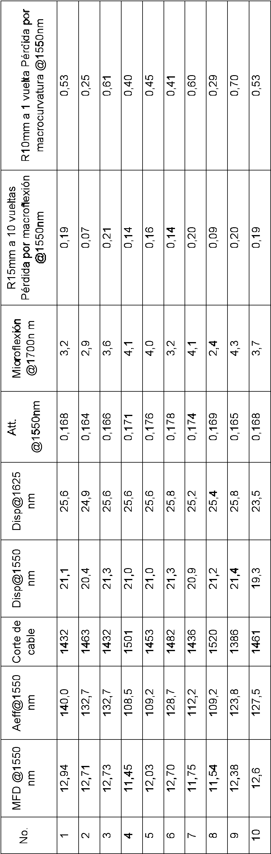
Claims (8)
Applications Claiming Priority (2)
| Application Number | Priority Date | Filing Date | Title |
|---|---|---|---|
| CN201510464355.0A CN104991307A (en) | 2015-07-31 | 2015-07-31 | Single-mode fiber with ultra-low attenuation and large effective area |
| PCT/CN2015/096106 WO2017020457A1 (en) | 2015-07-31 | 2015-12-01 | Ultra-low attenuation large effective area single-mode optical fiber |
Publications (1)
| Publication Number | Publication Date |
|---|---|
| ES2900735T3 true ES2900735T3 (en) | 2022-03-18 |
Family
ID=54303142
Family Applications (1)
| Application Number | Title | Priority Date | Filing Date |
|---|---|---|---|
| ES15900226T Active ES2900735T3 (en) | 2015-07-31 | 2015-12-01 | Ultra-low attenuation, wide effective area, single-mode optical fiber |
Country Status (8)
| Country | Link |
|---|---|
| US (1) | US10209437B2 (en) |
| EP (1) | EP3330756B1 (en) |
| JP (1) | JP6529666B2 (en) |
| KR (1) | KR20180006975A (en) |
| CN (1) | CN104991307A (en) |
| ES (1) | ES2900735T3 (en) |
| PL (1) | PL3330756T3 (en) |
| WO (1) | WO2017020457A1 (en) |
Families Citing this family (12)
| Publication number | Priority date | Publication date | Assignee | Title |
|---|---|---|---|---|
| CN104991307A (en) | 2015-07-31 | 2015-10-21 | 长飞光纤光缆股份有限公司 | Single-mode fiber with ultra-low attenuation and large effective area |
| CN106291808B (en) * | 2016-09-18 | 2019-05-24 | 长飞光纤光缆股份有限公司 | A kind of ultralow attenuation large effective area single mode optical fiber |
| JP7069566B2 (en) * | 2017-05-11 | 2022-05-18 | 住友電気工業株式会社 | Optical fiber |
| CN107422415B (en) * | 2017-06-15 | 2020-05-05 | 长飞光纤光缆股份有限公司 | Single-mode fiber with ultralow attenuation and large effective area |
| US11366266B2 (en) | 2017-07-03 | 2022-06-21 | Nippon Telegraph And Telephone Corporation | Optical fiber and optical transmission system |
| CN107490819B (en) * | 2017-08-22 | 2020-05-05 | 长飞光纤光缆股份有限公司 | Single mode optical fiber with ultra-low attenuation and large effective area |
| CN107678088A (en) * | 2017-11-09 | 2018-02-09 | 长飞光纤光缆股份有限公司 | The single-mode fiber of low attenuation large effective area |
| CN109445023B (en) * | 2018-11-07 | 2020-06-16 | 长飞光纤光缆股份有限公司 | Doping-optimized ultra-low attenuation single-mode fiber |
| CN111289021A (en) * | 2020-03-16 | 2020-06-16 | 中天科技光纤有限公司 | Optical fiber sensing device and detection system |
| US11776833B2 (en) | 2020-12-22 | 2023-10-03 | Canon Kabushiki Kaisha | Method for improving accuracy of imprint force application in imprint lithography |
| CN115542454A (en) * | 2022-10-28 | 2022-12-30 | 长飞光纤光缆股份有限公司 | Ultralow-loss single-mode optical fiber |
| AU2023203764A1 (en) * | 2022-12-30 | 2024-07-18 | Sterlite Technologies Limited | Optical fiber with an immediate fluorine cladding |
Family Cites Families (25)
| Publication number | Priority date | Publication date | Assignee | Title |
|---|---|---|---|---|
| US5146534A (en) * | 1991-11-12 | 1992-09-08 | At&T Bell Laboratories | SiO2 -based alkali-doped optical fiber |
| US6917740B2 (en) | 2003-05-30 | 2005-07-12 | Corning Incorporated | Optical fiber having reduced viscosity mismatch |
| US8798412B2 (en) * | 2003-08-29 | 2014-08-05 | Corning Incorporated | Optical fiber containing an alkali metal oxide and methods and apparatus for manufacturing same |
| US7088900B1 (en) * | 2005-04-14 | 2006-08-08 | Corning Incorporated | Alkali and fluorine doped optical fiber |
| US20070003198A1 (en) * | 2005-06-29 | 2007-01-04 | Lance Gibson | Low loss optical fiber designs and methods for their manufacture |
| FR2914751B1 (en) * | 2007-04-06 | 2009-07-03 | Draka Comteq France | OPTICAL FIBER MONOMODE |
| JP5013964B2 (en) | 2007-05-23 | 2012-08-29 | キヤノン株式会社 | Imaging apparatus and control method thereof |
| US8315495B2 (en) * | 2009-01-30 | 2012-11-20 | Corning Incorporated | Large effective area fiber with Ge-free core |
| US7689085B1 (en) * | 2009-01-30 | 2010-03-30 | Corning Incorporated | Large effective area fiber with GE-free core |
| FR2951282B1 (en) | 2009-10-13 | 2012-06-15 | Draka Comteq France | OPTICAL FIBER MONOMODE WITH TRANCHEE ENTERREE |
| EP2479150B1 (en) * | 2011-01-20 | 2013-09-18 | Sumitomo Electric Industries, Ltd. | Optical fiber preform, optical fiber, and method of manufacturing optical fiber preform |
| CN102156323B (en) * | 2011-05-05 | 2012-06-06 | 长飞光纤光缆有限公司 | Single mode fiber |
| ES2451369T3 (en) * | 2011-06-09 | 2014-03-26 | Draka Comteq Bv | Single mode fiber optic |
| US8687932B2 (en) * | 2011-09-21 | 2014-04-01 | Ofs Fitel, Llc | Optimized ultra large area optical fibers |
| JP5974455B2 (en) * | 2011-11-21 | 2016-08-23 | 住友電気工業株式会社 | Optical fiber preform, optical fiber manufacturing method, and optical fiber |
| US8666214B2 (en) * | 2011-11-30 | 2014-03-04 | Corning Incorporated | Low bend loss optical fiber |
| JP5831189B2 (en) * | 2011-12-09 | 2015-12-09 | 住友電気工業株式会社 | Optical fiber and optical transmission system |
| CN103454719B (en) | 2013-09-03 | 2015-09-30 | 长飞光纤光缆股份有限公司 | A kind of single-mode fiber |
| CN104360434B (en) * | 2014-11-12 | 2017-02-01 | 长飞光纤光缆股份有限公司 | Single mode fiber with ultralow-attenuation large effective area |
| CN104765098B (en) * | 2015-04-28 | 2018-03-16 | 长飞光纤光缆股份有限公司 | A kind of single-mode fiber having compared with lower attenuation coefficient |
| CN104749691B (en) * | 2015-04-28 | 2018-05-01 | 长飞光纤光缆股份有限公司 | A kind of ultralow attenuation bend-insensitive single-mode optical fiber |
| CN104777553B (en) * | 2015-04-28 | 2017-12-29 | 长飞光纤光缆股份有限公司 | A kind of ultralow decay single-mode fiber |
| CN104777551B (en) * | 2015-04-28 | 2018-03-16 | 长飞光纤光缆股份有限公司 | A kind of single-mode fiber of low attenuation large effective area |
| CN104898200B (en) * | 2015-06-25 | 2018-03-16 | 长飞光纤光缆股份有限公司 | A kind of ultralow decay single-mode fiber for adulterating optimization |
| CN104991307A (en) * | 2015-07-31 | 2015-10-21 | 长飞光纤光缆股份有限公司 | Single-mode fiber with ultra-low attenuation and large effective area |
-
2015
- 2015-07-31 CN CN201510464355.0A patent/CN104991307A/en active Pending
- 2015-12-01 PL PL15900226T patent/PL3330756T3/en unknown
- 2015-12-01 ES ES15900226T patent/ES2900735T3/en active Active
- 2015-12-01 JP JP2018516613A patent/JP6529666B2/en active Active
- 2015-12-01 EP EP15900226.0A patent/EP3330756B1/en active Active
- 2015-12-01 KR KR1020177036122A patent/KR20180006975A/en not_active Ceased
- 2015-12-01 WO PCT/CN2015/096106 patent/WO2017020457A1/en not_active Ceased
-
2018
- 2018-01-09 US US15/866,243 patent/US10209437B2/en active Active
Also Published As
| Publication number | Publication date |
|---|---|
| JP6529666B2 (en) | 2019-06-12 |
| EP3330756A1 (en) | 2018-06-06 |
| US10209437B2 (en) | 2019-02-19 |
| US20180128968A1 (en) | 2018-05-10 |
| PL3330756T3 (en) | 2022-04-11 |
| EP3330756B1 (en) | 2021-09-15 |
| JP2018517185A (en) | 2018-06-28 |
| WO2017020457A1 (en) | 2017-02-09 |
| KR20180006975A (en) | 2018-01-19 |
| EP3330756A4 (en) | 2018-08-15 |
| CN104991307A (en) | 2015-10-21 |
Similar Documents
| Publication | Publication Date | Title |
|---|---|---|
| ES2900735T3 (en) | Ultra-low attenuation, wide effective area, single-mode optical fiber | |
| US10151873B2 (en) | Single mode optical fiber with ultra-low attenuation and bend insensibility | |
| ES2381458T3 (en) | Fiber optic dispersion shifted | |
| ES2962308T3 (en) | Single-mode optical fiber with ultra-low loss and large effective area and manufacturing method thereof | |
| US9874687B2 (en) | Single-mode fiber with ultralow attenuation and large effective area | |
| CN107490819B (en) | Single mode optical fiber with ultra-low attenuation and large effective area | |
| CN107422415B (en) | Single-mode fiber with ultralow attenuation and large effective area | |
| CN103257393B (en) | Optical fiber large in effective area | |
| US10018779B2 (en) | Bending-insensitive single-mode fiber with ultra low attenuation | |
| CN104459876A (en) | Single-mode optical fiber with ultralow attenuation and large effective area | |
| US10514495B2 (en) | Single-mode fiber with ultra low attenuation | |
| CN104898201B (en) | A kind of single-mode fiber of ultralow attenuation large effective area | |
| CN104765098B (en) | A kind of single-mode fiber having compared with lower attenuation coefficient | |
| CN104777551B (en) | A kind of single-mode fiber of low attenuation large effective area | |
| CN104880766B (en) | A kind of ultralow decay single-mode fiber | |
| CN109683233A (en) | A kind of single mode optical fiber with ultralow attenuation large effective area | |
| WO2023240881A1 (en) | Land-type g.654.e optical fiber and manufacturing process therefor | |
| CN109683232A (en) | Single mode optical fiber with ultralow attenuation large effective area | |
| CN118567022A (en) | A single-mode optical fiber for dual-signal transmission of communication and sensing |