ES2928697T3 - Method for determining the vertical profile of the wind speed upstream of a wind turbine equipped with a laser remote sensing sensor - Google Patents
Method for determining the vertical profile of the wind speed upstream of a wind turbine equipped with a laser remote sensing sensor Download PDFInfo
- Publication number
- ES2928697T3 ES2928697T3 ES20178434T ES20178434T ES2928697T3 ES 2928697 T3 ES2928697 T3 ES 2928697T3 ES 20178434 T ES20178434 T ES 20178434T ES 20178434 T ES20178434 T ES 20178434T ES 2928697 T3 ES2928697 T3 ES 2928697T3
- Authority
- ES
- Spain
- Prior art keywords
- wind speed
- wind
- wind turbine
- measurement
- instant
- Prior art date
- Legal status (The legal status is an assumption and is not a legal conclusion. Google has not performed a legal analysis and makes no representation as to the accuracy of the status listed.)
- Active
Links
Classifications
-
- G—PHYSICS
- G01—MEASURING; TESTING
- G01S—RADIO DIRECTION-FINDING; RADIO NAVIGATION; DETERMINING DISTANCE OR VELOCITY BY USE OF RADIO WAVES; LOCATING OR PRESENCE-DETECTING BY USE OF THE REFLECTION OR RERADIATION OF RADIO WAVES; ANALOGOUS ARRANGEMENTS USING OTHER WAVES
- G01S17/00—Systems using the reflection or reradiation of electromagnetic waves other than radio waves, e.g. lidar systems
- G01S17/88—Lidar systems specially adapted for specific applications
- G01S17/95—Lidar systems specially adapted for specific applications for meteorological use
-
- F—MECHANICAL ENGINEERING; LIGHTING; HEATING; WEAPONS; BLASTING
- F03—MACHINES OR ENGINES FOR LIQUIDS; WIND, SPRING, OR WEIGHT MOTORS; PRODUCING MECHANICAL POWER OR A REACTIVE PROPULSIVE THRUST, NOT OTHERWISE PROVIDED FOR
- F03D—WIND MOTORS
- F03D17/00—Monitoring or testing of wind motors, e.g. diagnostics
-
- F—MECHANICAL ENGINEERING; LIGHTING; HEATING; WEAPONS; BLASTING
- F03—MACHINES OR ENGINES FOR LIQUIDS; WIND, SPRING, OR WEIGHT MOTORS; PRODUCING MECHANICAL POWER OR A REACTIVE PROPULSIVE THRUST, NOT OTHERWISE PROVIDED FOR
- F03D—WIND MOTORS
- F03D7/00—Controlling wind motors
-
- G—PHYSICS
- G01—MEASURING; TESTING
- G01P—MEASURING LINEAR OR ANGULAR SPEED, ACCELERATION, DECELERATION, OR SHOCK; INDICATING PRESENCE, ABSENCE, OR DIRECTION, OF MOVEMENT
- G01P21/00—Testing or calibrating of apparatus or devices covered by the preceding groups
- G01P21/02—Testing or calibrating of apparatus or devices covered by the preceding groups of speedometers
- G01P21/025—Testing or calibrating of apparatus or devices covered by the preceding groups of speedometers for measuring speed of fluids; for measuring speed of bodies relative to fluids
-
- G—PHYSICS
- G01—MEASURING; TESTING
- G01P—MEASURING LINEAR OR ANGULAR SPEED, ACCELERATION, DECELERATION, OR SHOCK; INDICATING PRESENCE, ABSENCE, OR DIRECTION, OF MOVEMENT
- G01P5/00—Measuring speed of fluids, e.g. of air stream; Measuring speed of bodies relative to fluids, e.g. of ship, of aircraft
- G01P5/26—Measuring speed of fluids, e.g. of air stream; Measuring speed of bodies relative to fluids, e.g. of ship, of aircraft by measuring the direct influence of the streaming fluid on the properties of a detecting optical wave
-
- G—PHYSICS
- G01—MEASURING; TESTING
- G01S—RADIO DIRECTION-FINDING; RADIO NAVIGATION; DETERMINING DISTANCE OR VELOCITY BY USE OF RADIO WAVES; LOCATING OR PRESENCE-DETECTING BY USE OF THE REFLECTION OR RERADIATION OF RADIO WAVES; ANALOGOUS ARRANGEMENTS USING OTHER WAVES
- G01S17/00—Systems using the reflection or reradiation of electromagnetic waves other than radio waves, e.g. lidar systems
- G01S17/02—Systems using the reflection of electromagnetic waves other than radio waves
- G01S17/50—Systems of measurement based on relative movement of target
- G01S17/58—Velocity or trajectory determination systems; Sense-of-movement determination systems
-
- G—PHYSICS
- G01—MEASURING; TESTING
- G01S—RADIO DIRECTION-FINDING; RADIO NAVIGATION; DETERMINING DISTANCE OR VELOCITY BY USE OF RADIO WAVES; LOCATING OR PRESENCE-DETECTING BY USE OF THE REFLECTION OR RERADIATION OF RADIO WAVES; ANALOGOUS ARRANGEMENTS USING OTHER WAVES
- G01S7/00—Details of systems according to groups G01S13/00, G01S15/00, G01S17/00
- G01S7/48—Details of systems according to groups G01S13/00, G01S15/00, G01S17/00 of systems according to group G01S17/00
- G01S7/4802—Details of systems according to groups G01S13/00, G01S15/00, G01S17/00 of systems according to group G01S17/00 using analysis of echo signal for target characterisation; Target signature; Target cross-section
-
- F—MECHANICAL ENGINEERING; LIGHTING; HEATING; WEAPONS; BLASTING
- F03—MACHINES OR ENGINES FOR LIQUIDS; WIND, SPRING, OR WEIGHT MOTORS; PRODUCING MECHANICAL POWER OR A REACTIVE PROPULSIVE THRUST, NOT OTHERWISE PROVIDED FOR
- F03D—WIND MOTORS
- F03D7/00—Controlling wind motors
- F03D7/02—Controlling wind motors the wind motors having rotation axis substantially parallel to the air flow entering the rotor
- F03D7/04—Automatic control; Regulation
-
- F—MECHANICAL ENGINEERING; LIGHTING; HEATING; WEAPONS; BLASTING
- F05—INDEXING SCHEMES RELATING TO ENGINES OR PUMPS IN VARIOUS SUBCLASSES OF CLASSES F01-F04
- F05B—INDEXING SCHEME RELATING TO WIND, SPRING, WEIGHT, INERTIA OR LIKE MOTORS, TO MACHINES OR ENGINES FOR LIQUIDS COVERED BY SUBCLASSES F03B, F03D AND F03G
- F05B2200/00—Mathematical features
- F05B2200/20—Special functions
- F05B2200/22—Power
-
- F—MECHANICAL ENGINEERING; LIGHTING; HEATING; WEAPONS; BLASTING
- F05—INDEXING SCHEMES RELATING TO ENGINES OR PUMPS IN VARIOUS SUBCLASSES OF CLASSES F01-F04
- F05B—INDEXING SCHEME RELATING TO WIND, SPRING, WEIGHT, INERTIA OR LIKE MOTORS, TO MACHINES OR ENGINES FOR LIQUIDS COVERED BY SUBCLASSES F03B, F03D AND F03G
- F05B2260/00—Function
- F05B2260/84—Modelling or simulation
-
- F—MECHANICAL ENGINEERING; LIGHTING; HEATING; WEAPONS; BLASTING
- F05—INDEXING SCHEMES RELATING TO ENGINES OR PUMPS IN VARIOUS SUBCLASSES OF CLASSES F01-F04
- F05B—INDEXING SCHEME RELATING TO WIND, SPRING, WEIGHT, INERTIA OR LIKE MOTORS, TO MACHINES OR ENGINES FOR LIQUIDS COVERED BY SUBCLASSES F03B, F03D AND F03G
- F05B2270/00—Control
- F05B2270/30—Control parameters, e.g. input parameters
- F05B2270/32—Wind speeds
-
- F—MECHANICAL ENGINEERING; LIGHTING; HEATING; WEAPONS; BLASTING
- F05—INDEXING SCHEMES RELATING TO ENGINES OR PUMPS IN VARIOUS SUBCLASSES OF CLASSES F01-F04
- F05B—INDEXING SCHEME RELATING TO WIND, SPRING, WEIGHT, INERTIA OR LIKE MOTORS, TO MACHINES OR ENGINES FOR LIQUIDS COVERED BY SUBCLASSES F03B, F03D AND F03G
- F05B2270/00—Control
- F05B2270/80—Devices generating input signals, e.g. transducers, sensors, cameras or strain gauges
- F05B2270/804—Optical devices
- F05B2270/8042—Lidar systems
-
- Y—GENERAL TAGGING OF NEW TECHNOLOGICAL DEVELOPMENTS; GENERAL TAGGING OF CROSS-SECTIONAL TECHNOLOGIES SPANNING OVER SEVERAL SECTIONS OF THE IPC; TECHNICAL SUBJECTS COVERED BY FORMER USPC CROSS-REFERENCE ART COLLECTIONS [XRACs] AND DIGESTS
- Y02—TECHNOLOGIES OR APPLICATIONS FOR MITIGATION OR ADAPTATION AGAINST CLIMATE CHANGE
- Y02A—TECHNOLOGIES FOR ADAPTATION TO CLIMATE CHANGE
- Y02A90/00—Technologies having an indirect contribution to adaptation to climate change
- Y02A90/10—Information and communication technologies [ICT] supporting adaptation to climate change, e.g. for weather forecasting or climate simulation
-
- Y—GENERAL TAGGING OF NEW TECHNOLOGICAL DEVELOPMENTS; GENERAL TAGGING OF CROSS-SECTIONAL TECHNOLOGIES SPANNING OVER SEVERAL SECTIONS OF THE IPC; TECHNICAL SUBJECTS COVERED BY FORMER USPC CROSS-REFERENCE ART COLLECTIONS [XRACs] AND DIGESTS
- Y02—TECHNOLOGIES OR APPLICATIONS FOR MITIGATION OR ADAPTATION AGAINST CLIMATE CHANGE
- Y02E—REDUCTION OF GREENHOUSE GAS [GHG] EMISSIONS, RELATED TO ENERGY GENERATION, TRANSMISSION OR DISTRIBUTION
- Y02E10/00—Energy generation through renewable energy sources
- Y02E10/70—Wind energy
- Y02E10/72—Wind turbines with rotation axis in wind direction
Landscapes
- Engineering & Computer Science (AREA)
- Physics & Mathematics (AREA)
- General Physics & Mathematics (AREA)
- Electromagnetism (AREA)
- Computer Networks & Wireless Communication (AREA)
- Radar, Positioning & Navigation (AREA)
- Remote Sensing (AREA)
- Sustainable Development (AREA)
- Life Sciences & Earth Sciences (AREA)
- Sustainable Energy (AREA)
- Chemical & Material Sciences (AREA)
- Combustion & Propulsion (AREA)
- Mechanical Engineering (AREA)
- General Engineering & Computer Science (AREA)
- Multimedia (AREA)
- Aviation & Aerospace Engineering (AREA)
- Wind Motors (AREA)
- Optical Radar Systems And Details Thereof (AREA)
Abstract
La invención se refiere a un método para determinar el perfil vertical de la velocidad del viento aguas arriba de un aerogenerador (1), para lo cual se toman medidas de la velocidad del viento por medio de un sensor LIDAR (2), luego se determina el exponente de ley de potencia α mediante un filtro de Kalman sin olor y mediciones, y este exponente α se aplica a la ley de potencia para determinar el perfil vertical de la velocidad del viento. (Traducción automática con Google Translate, sin valor legal)The invention refers to a method for determining the vertical profile of the wind speed upstream of a wind turbine (1), for which wind speed measurements are taken by means of a LIDAR sensor (2), then it is determined the power law exponent α using an odorless Kalman filter and measurements, and this exponent α is applied to the power law to determine the vertical wind speed profile. (Automatic translation with Google Translate, without legal value)
Description
DESCRIPCIÓNDESCRIPTION
Método de determinación del perfil vertical de la velocidad del viento flujo arriba de un aerogenerador provisto de un sensor de teledetección por laserMethod for determining the vertical profile of the wind speed upstream of a wind turbine equipped with a laser remote sensing sensor
CAMPO TÉCNICOTECHNICAL FIELD
La presente invención se refiere al campo de las energías renovables, y más en particular se refiere a la medición del recurso de los aerogeneradores, el viento, en objetivos de predicción del viento, de control (orientación, regulación del par y de la velocidad) y/o de diagnóstico y/o de vigilancia del aerogenerador.The present invention refers to the field of renewable energies, and more particularly it refers to the measurement of the resource of wind turbines, the wind, for purposes of wind prediction, control (orientation, torque and speed regulation) and/or diagnosis and/or monitoring of the wind turbine.
Un aerogenerador permite transformar la energía cinética del viento en energía eléctrica o mecánica. Para la conversión del viento en energía eléctrica, el aerogenerador dispone de los elementos siguientes:A wind turbine transforms the kinetic energy of the wind into electrical or mechanical energy. For the conversion of wind into electrical energy, the wind turbine has the following elements:
- un mástil que permite colocar un rotor a una altura suficiente para permitir su movimiento (necesario para los aerogeneradores de eje horizontal) y/o colocar dicho rotor a una altura que le permita ser impulsado por un viento más fuerte y regular que al nivel del suelo. El mástil, por lo general, aloja parte de los componentes eléctricos y electrónicos (modulador, control, multiplicador, generador, etc.);- a mast that allows a rotor to be placed at a height sufficient to allow its movement (necessary for horizontal axis wind turbines) and/or said rotor to be placed at a height that allows it to be driven by a stronger and more regular wind than at sea level. I usually. The mast generally houses part of the electrical and electronic components (modulator, control, multiplier, generator, etc.);
- una barquilla montada en la parte superior del mástil, que aloja componentes mecánicos, neumáticos, algunos componentes eléctricos y electrónicos, necesarios para el funcionamiento de la máquina. La barquilla puede girar para orientar la máquina en la dirección correcta;- a basket mounted on the upper part of the mast, which houses mechanical and pneumatic components, some electrical and electronic components, necessary for the operation of the machine. The nacelle can rotate to orient the machine in the right direction;
- un rotor, fijado a la barquilla, formado por varias palas (normalmente tres) y el cono frontal del aerogenerador. El rotor es impulsado por la energía del viento, está conectado por un eje mecánico directa o indirectamente (a través de un sistema de caja de cambios y eje mecánico) a una máquina eléctrica (generador eléctrico...) que convierte la energía recogida en energía eléctrica. El rotor está potencialmente provisto de sistemas de control tales como un sistema de control de las palas de ángulo variable o un sistema de control de los frenos aerodinámicos; - A rotor, fixed to the nacelle, made up of several blades (usually three) and the frontal cone of the wind turbine. The rotor is driven by wind energy, it is connected by a mechanical shaft directly or indirectly (through a gearbox system and mechanical shaft) to an electrical machine (electric generator...) that converts the collected energy into electric power. The rotor is potentially provided with control systems such as a variable angle blade control system or aerodynamic brake control system;
- una transmisión, compuesta por dos ejes (eje mecánico del rotor y eje mecánico de la máquina eléctrica) conectados por una transmisión (caja de cambios).- a transmission, composed of two axes (mechanical axis of the rotor and mechanical axis of the electrical machine) connected by a transmission (gearbox).
Desde principios de la década de 1990, la energía eólica ha experimentado un renovado interés, particularmente en la Unión Europea en donde la tasa de crecimiento anual es de alrededor del 20%. Este crecimiento se atribuye a la posibilidad inherente de generar electricidad sin emisiones de carbono. Para respaldar este crecimiento, se debe seguir mejorando el rendimiento de los aerogeneradores. La perspectiva de aumentar la producción de energía eólica requiere el desarrollo de herramientas de producción eficientes y de herramientas de control avanzado para mejorar el rendimiento de las máquinas. Los aerogeneradores están diseñados para producir electricidad al precio más bajo posible. Por lo tanto, los aerogeneradores por lo general se construyen de tal manera que alcanzan su máximo rendimiento para una velocidad del viento de alrededor de 15 m/s. No es necesario diseñar aerogeneradores que maximicen su rendimiento a velocidades de viento más altas, que son poco frecuentes. En caso de velocidades del viento superiores a 15 m/s, es necesario perder parte de la energía adicional contenida en el viento con el fin de evitar cualquier daño al aerogenerador. Por lo tanto, todos los aerogeneradores están diseñados con un sistema de regulación de la potencia.Since the early 1990s, wind power has experienced renewed interest, particularly in the European Union where the annual growth rate is around 20%. This growth is attributed to the inherent possibility of generating electricity without carbon emissions. To support this growth, the performance of wind turbines must continue to be improved. The perspective of increasing the production of wind energy requires the development of efficient production tools and advanced control tools to improve the performance of the machines. Wind turbines are designed to produce electricity at the lowest possible price. Therefore, wind turbines are usually built in such a way that they reach their maximum performance for a wind speed of around 15 m/s. There is no need to design wind turbines that maximize their performance at higher wind speeds, which are rare. In case of wind speeds higher than 15 m/s, it is necessary to lose part of the additional energy contained in the wind in order to avoid any damage to the wind turbine. Therefore, all wind turbines are designed with a power regulation system.
Para esta regulación de potencia se diseñan controladores para aerogeneradores de velocidad variable. Los objetivos de los controladores son maximizar la energía eléctrica recuperada, minimizar las fluctuaciones de velocidad del rotor y minimizar la fatiga y los instantes extremos de la estructura (palas, mástil y plataforma).For this power regulation, controllers for variable speed wind turbines are designed. The objectives of the controllers are to maximize the electrical energy recovered, to minimize the speed fluctuations of the rotor and to minimize the fatigue and the extreme moments of the structure (blades, mast and platform).
TÉCNICA ANTERIORPRIOR ART
Para optimizar el control, es importante conocer la velocidad del viento al nivel del rotor del aerogenerador. Para ello se han desarrollado diferentes técnicas.To optimize control, it is important to know the wind speed at the level of the wind turbine rotor. For this, different techniques have been developed.
Según una primera técnica, el uso de un anemómetro permite estimar una velocidad del viento en un punto, pero esta tecnología imprecisa no permite medir la totalidad de un campo de viento ni conocer las componentes tridimensionales de la velocidad del viento o conocer el perfil vertical de la velocidad del viento.According to a first technique, the use of an anemometer makes it possible to estimate a wind speed at a point, but this imprecise technology does not make it possible to measure the entirety of a wind field or to know the three-dimensional components of the wind speed or to know the vertical profile of the speed of the wind
Según una segunda técnica, se puede utilizar un sensor LIDAR (acrónimo de la expresión en inglés “light detection and range” que puede traducirse como teledetección por láser). LIDAR es una tecnología de teledetección o de medición óptica basada en el análisis de las propiedades de un haz reenviado hacia su emisor. Este método se utiliza en particular para determinar la distancia a un objeto por medio de un láser pulsado. A diferencia del radar basado en un principio similar, el sensor LIDAR utiliza luz visible o infrarroja en lugar de ondas de radio. La distancia a un objeto o superficie se obtiene midiendo el retardo entre el impulso y la detección de la señal reflejada. According to a second technique, a LIDAR sensor (acronym for the English expression "light detection and range" which can be translated as laser remote sensing) can be used. LIDAR is a remote sensing or optical measurement technology based on the analysis of the properties of a beam forwarded towards its emitter. This method is used in particular to determine the distance to an object by means of a pulsed laser. Unlike radar based on a similar principle, the LIDAR sensor uses visible or infrared light instead of radio waves. The distance to an object or surface is obtained by measuring the delay between the impulse and the detection of the reflected signal.
En el campo de los aerogeneradores, el sensor LIDAR se anuncia como un sensor imprescindible para el buen funcionamiento de los grandes aerogeneradores, especialmente a medida que aumentan su tamaño y potencia (actualmente, 5 MW, y próximamente 12 MW offshore). Este sensor permite la medición a distancia del viento, que permite inicialmente calibrar los aerogeneradores para que puedan proporcionar la máxima potencia (optimización de la curva de potencia). Para esta etapa de calibración, el sensor puede colocarse en el suelo y orientarse verticalmente (perfilar), lo que permite medir la velocidad del viento y su dirección, así como el gradiente del viento según las altitudes. Esta aplicación es particularmente crítica puesto que permite conocer el recurso productor de energía. Lo que antecede es importante para los proyectos eólicos, ya que condiciona la fiabilidad financiera del proyecto. Sin embargo, este método puede parecer costoso, ya que requiere un sensor LIDAR colocado de forma fija en el suelo o en el mar y orientado verticalmente, además del sensor LIDAR colocado en el aerogenerador para la aplicación que se describe a continuación.In the field of wind turbines, the LIDAR sensor is announced as an essential sensor for the proper functioning of large wind turbines, especially as their size and power increase (currently 5 MW, and soon 12 MW offshore). This sensor allows remote measurement of the wind, which initially allows the wind turbines to be calibrated so that they can provide maximum power (optimization of the power curve). For this calibration stage, the sensor can be placed on the ground and oriented vertically (profiling), which makes it possible to measure the wind speed and its direction, as well as the wind gradient depending on the altitudes. This application is particularly critical since it allows knowing the energy producing resource. The foregoing is important for wind projects, since it conditions the financial reliability of the project. However, this method may seem expensive, as it requires a lidar sensor fixed on the ground or in the sea and oriented vertically, in addition to the lidar sensor placed on the wind turbine for the application described below.
Una segunda aplicación es la colocación de este sensor en la barquilla del aerogenerador, para medir el campo de viento delante del aerogenerador mientras está orientado casi horizontalmente. A priori, la medición del campo de viento delante del aerogenerador permite conocer de antemano las turbulencias que encontrará el aerogenerador unos instantes después. Sin embargo, las técnicas actuales de control y de seguimiento de un aerogenerador no permiten tener en cuenta una medición realizada por un sensor LIDAR estimando, con precisión, la velocidad del viento al nivel del rotor, es decir, en el plano del rotor. Dicha aplicación se describe, en particular, en la solicitud de patente FR 3013777 (US 2015145253).A second application is the placement of this sensor in the nacelle of the wind turbine, to measure the wind field in front of the wind turbine while it is oriented almost horizontally. A priori, the measurement of the wind field in front of the wind turbine allows us to know in advance the turbulence that the wind turbine will encounter a few moments later. However, current wind turbine control and monitoring techniques do not allow a measurement made by a LIDAR sensor to be taken into account by accurately estimating the wind speed at rotor level, that is, in the plane of the rotor. Such an application is described, in particular, in the patent application FR 3013777 (US 2015145253).
La velocidad del viento varía en función de la altitud: el viento es mayor a gran altura que a nivel del suelo. El conocimiento del perfil vertical de la velocidad del viento, dicho de otro modo, el gradiente de la velocidad del viento en función de la altitud, es de utilidad en diferentes aplicaciones de control de aerogeneradores. Documento Wagner, Rozenn & Antoniou, Loannis & M. Pedersen, Soren & Courtney, Michael & Jorgensen, Hans. (2009). La influencia del perfil de velocidad del viento en las medidas de rendimiento del aerogenerador. Wind Energy. 12. 348-362.10.1002/we.297, describe, en particular, la relación entre el perfil de la velocidad del viento y los rendimientos del aerogenerador. Según varios ejemplos, este perfil vertical de la velocidad del viento se puede utilizar en las evaluaciones de la energía del aerogenerador o en el control del ángulo de inclinación (el ángulo de orientación) de las palas del aerogenerador.Wind speed varies with altitude: the wind is stronger at high altitude than at ground level. Knowledge of the vertical profile of the wind speed, in other words, the gradient of the wind speed as a function of altitude, is useful in different wind turbine control applications. Document Wagner, Rozenn & Antoniou, Loannis & M. Pedersen, Soren & Courtney, Michael & Jorgensen, Hans. (2009). The influence of the wind speed profile on the performance measurements of the wind turbine. Wind Energy. 12. 348-362.10.1002/we.297, describes, in particular, the relationship between the wind speed profile and the performance of the wind turbine. According to various examples, this vertical wind speed profile can be used in wind turbine power assessments or in pitch angle control (the yaw angle) of the wind turbine blades.
De manera convencional, el perfil vertical de la velocidad del viento utilizado por los fabricantes de sensores LIDAR se obtiene mediante métodos aplicados fuera de línea basados en el enfoque de procesamiento por lotes. Por consiguiente, estos métodos no son adecuados para estimar el perfil vertical de la velocidad del viento en tiempo real. Además, otros métodos de determinación del perfil vertical de la velocidad del viento utilizan representaciones matemáticas del mismo, incluyendo: el perfil logarítmico o la ley de potencia.Conventionally, the vertical wind speed profile used by LIDAR sensor manufacturers is obtained by offline applied methods based on the batch approach. Consequently, these methods are not suitable for estimating the vertical profile of wind speed in real time. In addition, other methods of determining the vertical profile of the wind speed use mathematical representations of it, including: the logarithmic profile or the power law.
El perfil logarítmico del viento se creó a partir de un modelo de la capa límite turbulenta en una placa plana de Prandtl. Más tarde se descubrió que era válido en forma no modificada en vientos fuertes en la capa límite atmosférica en la proximidad de la superficie terrestre o del mar. En la superficie, el perfil logarítmico del viento viene dado porThe logarithmic wind profile was created from a model of the turbulent boundary layer on a flat Prandtl plate. It was later found to be valid in unchanged form in strong winds in the atmospheric boundary layer in the vicinity of the land or sea surface. At the surface, the logarithmic profile of the wind is given by

en donde vz es la velocidad longitudinal del viento a la altitud z, v* es la velocidad de fricción, k=0,41 es la constante de Von Karman, z0 es la rugosidad de la superficie, ^m la corrección diabática del perfil vertical de la velocidad del viento. Este perfil logarítmico depende solamente de constantes y es inexacto a grandes altitudes y es difícil de calibrar. Además, este perfil logarítmico es menos preciso que la ley de potencia.where vz is the longitudinal wind speed at altitude z, v* is the friction speed, k=0.41 is the von Karman constant, z 0 is the surface roughness, ^m the diabatic correction of the profile vertical wind speed. This logarithmic profile depends only on constants and is inaccurate at high altitudes and is difficult to calibrate. Also, this logarithmic profile is less accurate than the power law.
En cuanto a lo que antecede, la ley de potencia se expresa por:Regarding the above, the power law is expressed by:

siendo vz la velocidad longitudinal del viento a la altura z, zo la altura de referencia, vz0 la velocidad longitudinal del viento a la altura de referencia z0 y a el exponente de dicha ley de potencia.where vz is the longitudinal wind speed at height z, zo is the reference height, vz 0 is the longitudinal wind speed at the reference height z 0 and is the exponent of said power law.
Esta ley de potencia se suele utilizar en las evaluaciones de la energía eólica, en donde la velocidad del viento a la altura de un aerogenerador debe estimarse a partir de observaciones del viento en la proximidad de la superficie, o donde los datos de la velocidad del viento, a diferentes alturas, deben ajustarse a una altura estándar. En comparación con la ley logarítmica, la ley de potencia se puede integrar con facilidad en una altura: este perfil se utiliza, en gran medida, con fines de ingeniería debido a su simplicidad. Suponiendo condiciones atmosféricas neutras, es bien sabido que la ley de potencia produce predicciones más precisas de la velocidad del viento que la ley logarítmica, desde 100 m en la proximidad de la parte superior de la capa límite atmosférica. Para condiciones normales de viento en lugar offshore (en alta mar), el exponente a se establece en 1/7. Sin embargo, cuando se utiliza un exponente constante, no tiene en cuenta la variación en función del tiempo y la rugosidad de la superficie. Además, no tiene en cuenta el desplazamiento de los vientos superficiales debido a la presencia de obstáculos, que es el aerogenerador en nuestro caso. Por lo tanto, utilizar un exponente constante puede proporcionar estimaciones bastantes erróneas del perfil vertical de la velocidad del viento.This power law is often used in wind energy assessments, where the wind speed at the height of a wind turbine must be estimated from near-surface wind observations, or where wind speed data wind, at different heights, should be adjusted to a standard height. Compared to the logarithmic law, the power law can be easily integrated into a height: this profile is largely used for engineering purposes due to its simplicity. Assuming neutral atmospheric conditions, it is well known that the power law produces more accurate wind speed predictions than the logarithmic law, from 100 m in the vicinity of the top of the atmospheric boundary layer. For normal offshore wind conditions, the exponent a is set to 1/7. However, when a constant exponent is used, it does not take into account the variation as a function of time and the roughness of the surface. Furthermore, it does not take into account the displacement of surface winds due to the presence of obstacles, which is the wind turbine in our case. Therefore, using a constant exponent can give grossly inaccurate estimates of the vertical wind speed profile.
SUMARIO DE LA INVENCIÓNSUMMARY OF THE INVENTION
La presente invención tiene como objeto, en particular, determinar, en tiempo real, un perfil vertical preciso de la velocidad del viento de una manera sencilla. Para ello, la invención se refiere a un método de determinación del perfil vertical de la velocidad del viento flujo arriba de un aerogenerador, para el cual se realizan medidas de la velocidad del viento mediante un sensor LIDAR, a continuación, se determina el exponente a de la ley de potencia mediante un filtro de Kalman inoloro y a continuación, se aplica este exponente a a la ley de potencia para determinar el perfil vertical de la velocidad del viento.The object of the present invention is, in particular, to determine, in real time, an accurate vertical profile of the wind speed in a simple manner. To this end, the invention refers to a method for determining the vertical profile of the wind speed upstream of a wind turbine, for which wind speed measurements are made using a LIDAR sensor, then the exponent a is determined. of the power law using an odorless Kalman filter, and then this exponent a is applied to the power law to determine the vertical wind speed profile.
La invención se refiere a un método de determinación del perfil vertical de la velocidad del viento flujo arriba de un aerogenerador, estando dicho aerogenerador provisto de un sensor LIDAR dirigido flujo arriba de dicho aerogenerador, en donde se ponen en práctica las etapas siguientes:The invention refers to a method for determining the vertical profile of the wind speed upstream of a wind turbine, said wind turbine being provided with a LIDAR sensor directed upstream of said wind turbine, where the following steps are put into practice:
a) Se mide la velocidad del viento en al menos un plano de medida flujo arriba de dicho aerogenerador en al menos dos puntos de medida ubicados a diferentes altitudes mediante dicho sensor LIDAR;a) The wind speed is measured in at least one measurement plane upstream of said wind turbine in at least two measurement points located at different altitudes by means of said LIDAR sensor;
b) Se construye un modelo de perfil vertical de la velocidad del viento utilizando una ley de potencia de la formab) A vertical profile model of the wind speed is constructed using a power law of the form

siendo vz la velocidad longitudinal del viento a la altura z, zo la altura de referencia, vz0 la velocidad longitudinal del viento a la altura de referencia z0 y a el exponente de dicha ley de potencia;where vz is the longitudinal speed of the wind at height z, zo the reference height, vz 0 is the longitudinal speed of the wind at the reference height z 0 and is the exponent of said power law;
c) se determina dicho exponente a de dicha ley de potencia mediante un filtro de Kalman inoloro mediante dichas medidas de la velocidad del viento en dichos dos puntos de medida; yc) said exponent a of said power law is determined by means of an odorless Kalman filter by means of said measurements of the wind speed at said two measurement points; Y
d) se determina dicho perfil vertical de la velocidad del viento aplicando dicho exponente a determinado a dicho modelo de perfil vertical de la velocidad del viento.d) said vertical wind speed profile is determined by applying said exponent a determined to said vertical wind speed profile model.
Según una forma de realización de la invención, se aplica dicho filtro de Kalman inoloro a un modelo de estado que comprende ruido aditivo y ruido multiplicativo.According to an embodiment of the invention, said odorless Kalman filter is applied to a state model comprising additive noise and multiplicative noise.
De manera ventajosa, dicho modelo de estado se expresa por:Advantageously, said state model is expressed by:

Siendo x(k)=a(k) la variable de estado en el instante k, y(k)=v1 (k) la salida de dicho modelo de estado correspondiente a la velocidad longitudinal del viento medida en el instante k en el punto de medida 1, n(k-1) es la variación del exponente a en el instante k-1, v2(k) la velocidad longitudinal del viento medida en el instante k en el punto de medida 2, z1 la altitud del punto de medida 1, z2 la altitud de punto de medida 2, s1 (k) el ruido de la velocidad v1 en el instante k, y s2(k) el ruido de la velocidad v2 en el instante k.Being x(k)=a(k) the state variable at instant k, and y(k)=v1 (k) the output of said state model corresponding to the longitudinal wind speed measured at instant k at point of measurement 1, n(k-1) is the variation of the exponent a at instant k-1, v2(k) the longitudinal speed of the wind measured at instant k at measurement point 2, z1 the altitude of the measurement point measurement 1, z2 the altitude of measurement point 2, s1(k) the noise of velocity v1 at instant k, and s2(k) the noise of velocity v2 at instant k.
De manera preferente, para la aplicación de dicho filtro de Kalman se considera la variable aleatoria aumentada xaPreferably, for the application of said Kalman filter, the augmented random variable xa is considered

Siendo x(k)=a(k) la variable de estado en el instante k y s2(k) el ruido de la velocidad v2 en el instante k. Según un aspecto, se determina dicho exponente a de dicha ley de potencia mediante las etapas siguientes:Being x(k)=a(k) the state variable at instant k and s2(k) the noise of velocity v2 at instant k. According to one aspect, said exponent a of said power law is determined by the following steps:
i) se inicializa k=0, el vector de estado xa(0|0)=m(0) y el estado de la matriz de covarianza, P(0|0)=P0; ii) en cada instante k se adquieren dichas medidas v1 (k) y v2(k) de la velocidad del viento en los puntos de medida 1 y 2, siendo y(k)=v1 (k); yi) k=0 is initialized, the state vector xa(0|0)=m(0) and the state of the covariance matrix, P(0|0)=P0; ii) at each instant k said measurements v1(k) and v2(k) of the wind speed at measurement points 1 and 2 are acquired, where y(k)=v1(k); Y
iii) en cada instante k, se determina dicho exponente a de dicha ley de potencia mediante las ecuaciones siguientes:iii) at each instant k, said exponent a of said power law is determined by means of the following equations:

Siendo K la ganancia del filtro de Kalman, Pxy la covarianza cruzada del estado y de la medida, Pyy la covarianza prevista de la medida, my la media prevista de la salida, v1 (k) la velocidad longitudinal del viento medida en el instante k en el punto de medida 1.Where K is the gain of the Kalman filter, Pxy is the cross-state and measurement covariance, Pyy is the predicted covariance of the measurement, m is the predicted mean of the output, v1 (k) is the measured longitudinal wind speed at instant k at measuring point 1.
Además, la invención se refiere a un método de control de un aerogenerador provisto de un sensor LIDAR, en donde se ponen en práctica las etapas siguientes:In addition, the invention refers to a control method for a wind turbine provided with a LIDAR sensor, where the following steps are put into practice:
a) se determina dicho perfil vertical de la velocidad del viento flujo arriba del aerogenerador mediante el método según una de las características anteriores;a) said vertical profile of the wind speed upstream of the wind turbine is determined by the method according to one of the previous characteristics;
b) se controla dicho aerogenerador en función de dicho perfil vertical de la velocidad del viento flujo arriba de dicho aerogenerador.b) said wind turbine is controlled as a function of said vertical profile of the wind speed upstream of said wind turbine.
La invención también se refiere a un producto de programa informático que comprende instrucciones de código dispuestas para poner en práctica las etapas de un método según una de las características anteriores, cuando el programa se ejecuta en una unidad de procesamiento de dicho sensor LIDAR.The invention also relates to a computer program product comprising code instructions arranged to implement the steps of a method according to one of the above features, when the program is executed in a processing unit of said LIDAR sensor.
Además, la invención se refiere a un sensor LIDAR para un aerogenerador. Comprende una unidad de procesamiento que pone en práctica un método según una de las características anteriores.Furthermore, the invention relates to a LIDAR sensor for a wind turbine. It comprises a processing unit that implements a method according to one of the above features.
Además, la invención se refiere a un aerogenerador que comprende un sensor LIDAR según una de las características anteriores, estando situado dicho sensor LIDAR, de manera preferente, en la barquilla de dicho aerogenerador o en el cono frontal del aerogenerador.In addition, the invention refers to a wind turbine comprising a LIDAR sensor according to one of the above characteristics, said LIDAR sensor being preferably located in the nacelle of said wind turbine or in the frontal cone of the wind turbine.
Otras características y ventajas del método, según la invención, aparecerán con la lectura de la siguiente descripción de ejemplos de formas de realización no limitativas, con referencia a las figuras adjuntas y descritas a continuación. LISTA DE LAS FIGURASOther characteristics and advantages of the method, according to the invention, will appear upon reading the following description of examples of non-limiting embodiments, with reference to the figures attached and described below. LIST OF FIGURES
La Figura 1 ilustra un aerogenerador provisto de un sensor LIDAR según una forma de realización de la invención. La Figura 2 ilustra las etapas del método de determinación del perfil vertical de la velocidad del viento según una forma de realización de la invención.Figure 1 illustrates a wind turbine provided with a LIDAR sensor according to an embodiment of the invention. Figure 2 illustrates the steps of the wind speed vertical profile determination method according to an embodiment of the invention.
La Figura 3 ilustra las etapas del método de control de un aerogenerador según una segunda forma de realización de la invención.Figure 3 illustrates the steps of the control method of a wind turbine according to a second embodiment of the invention.
La Figura 4 es una curva de la velocidad radial del viento medida a dos alturas, 200 m flujo arriba del aerogenerador, en función del tiempo, a modo de ejemplo.Figure 4 is a curve of the radial velocity of the wind measured at two heights, 200 m upstream of the wind turbine, as a function of time, as an example.
La Figura 5 es una curva de la velocidad longitudinal estimada a dos alturas, 200 m flujo arriba del aerogenerador, en función del tiempo, para el ejemplo de la Figura 4.Figure 5 is a curve of the estimated longitudinal velocity at two heights, 200 m upstream of the wind turbine, as a function of time, for the example of Figure 4.
La Figura 6 es un ejemplo de curva de variación del exponente a en función del tiempo para el ejemplo de la Figura 4. Figure 6 is an example of a curve for the variation of the exponent a as a function of time for the example of Figure 4.
La Figura 7 es una curva de la velocidad longitudinal estimada mediante el método según una forma de realización de la invención (a partir de las medidas del ejemplo de la Figura 4) y medida, 100 m flujo arriba del aerogenerador, en función del tiempo.Figure 7 is a curve of the longitudinal speed estimated by the method according to an embodiment of the invention (from the measurements of the example of Figure 4) and measured, 100 m upstream of the wind turbine, as a function of time.
DESCRIPCIÓN DE LAS FORMAS DE REALIZACIÓNDESCRIPTION OF THE EMBODIMENTS
La presente invención se refiere a un método de determinación del perfil vertical de la velocidad del viento flujo arriba de un aerogenerador (la noción de “flujo arriba” se define según la dirección del viento hacia el aerogenerador). Se denomina perfil vertical de la velocidad del viento al gradiente de la velocidad del viento en función de la altitud. El perfil vertical determinado de la velocidad del viento permite determinar la variación vertical del viento flujo arriba del aerogenerador y al nivel del plano del rotor del aerogenerador. Según la invención, el aerogenerador está provisto de un sensor LIDAr que está dispuesto prácticamente horizontal para medir la velocidad del viento flujo arriba del aerogenerador.The present invention refers to a method for determining the vertical profile of the wind speed upstream of a wind turbine (the notion of "upstream" is defined according to the direction of the wind towards the wind turbine). The vertical profile of the wind speed is called the gradient of the wind speed as a function of altitude. The determined vertical profile of the wind speed makes it possible to determine the vertical variation of the wind upstream of the wind turbine and at the level of the plane of the wind turbine rotor. According to the invention, the wind turbine is provided with a LIDAr sensor that is arranged practically horizontally to measure the speed of the wind upstream of the wind turbine.
Según la invención, el sensor LIDAR permite medir la velocidad del viento en al menos un plano de medida flujo arriba del aerogenerador. Existen varios tipos de sensores LIDAR, por ejemplo, los sensores LIDAR escaneados, LIDAR continuos o LIDAR pulsados. En el contexto de la invención, se utiliza, de manera preferente, un LIDAR pulsado. Sin embargo, las otras tecnologías LIDAR pueden utilizarse mientras permanecen dentro del alcance de la invención. According to the invention, the LIDAR sensor makes it possible to measure the wind speed in at least one measurement plane upstream of the wind turbine. There are several types of LIDAR sensors, for example, scanned LIDAR, continuous LIDAR, or pulsed LIDAR sensors. In the context of the invention, a pulsed LIDAR is preferably used. However, the other LIDAR technologies can be used while remaining within the scope of the invention.
El sensor LIDAR permite una medida rápida. Por lo tanto, el uso de un sensor de este tipo permite una determinación rápida, continua y en tiempo real del perfil vertical de la velocidad del viento. Por ejemplo, la tasa de muestreo del sensor LIDAR puede estar comprendida entre 1 y 5 Hz (incluso más en el futuro), y puede valer 4 Hz. Además, el sensor LIDAR permite obtener información relativa al viento flujo arriba del aerogenerador, estando esta información ligada al viento que llegará al aerogenerador. Por lo tanto, el sensor LIDAR se puede utilizar para la determinación del perfil vertical de la velocidad del viento.The LIDAR sensor allows a fast measurement. Therefore, the use of such a sensor allows a fast, continuous and real-time determination of the vertical profile of the wind speed. For example, the sampling rate of the LIDAR sensor can be between 1 and 5 Hz (even more in the future), and can be worth 4 Hz. In addition, the LIDAR sensor allows obtaining information related to the wind upstream of the wind turbine, while this information linked to the wind that will reach the wind turbine. Therefore, the LIDAR sensor can be used for the determination of the vertical profile of the wind speed.
La Figura 1 muestra, de forma esquemática y no limitativa, un aerogenerador 1 de eje horizontal provisto de un sensor LIDAR 2 para el método según una forma de realización de la invención. El sensor LIDAR 2 se utiliza para medir la velocidad del viento a una distancia dada en una pluralidad de planos de medida PM (solamente se representan dos planos de medida). Conocer la medida del viento de antemano permite proporcionar, a priori, numerosa información. Esta figura también muestra los ejes x, y y z. El punto de referencia de esta marca es el centro del rotor. La dirección x es la dirección longitudinal, correspondiente a la dirección del eje del rotor, flujo arriba del aerogenerador, esta dirección también corresponde a la dirección de medida del sensor LIDAR 2. La dirección y, perpendicular a la dirección x, es la dirección lateral ubicada en un plano horizontal (las direcciones x, y forman un plano horizontal). La dirección z es la dirección vertical (correspondiente prácticamente a la dirección del mástil 4) dirigida hacia arriba, siendo el eje z perpendicular a los ejes x e y. El plano del rotor está indicado por el rectángulo en líneas de puntos PR, estando definido por las direcciones y, z para un valor de x nulo. Los planos de medida PM son planos formados por las direcciones y, z a una distancia del plano del rotor PR (para un valor de x distinto de cero). Los planos de medida PM son paralelos al plano del rotor PR.Figure 1 shows, schematically and without limitation, a horizontal axis wind turbine 1 provided with a LIDAR sensor 2 for the method according to an embodiment of the invention. The LIDAR 2 sensor is used to measure the wind speed at a given distance in a plurality of PM measurement planes (only two measurement planes are shown). Knowing the measurement of the wind in advance makes it possible to provide, a priori, a great deal of information. This figure also shows the x, y, and z axes. The reference point of this mark is the center of the rotor. The x direction is the longitudinal direction, corresponding to the direction of the rotor axis, upstream of the wind turbine, this direction also corresponds to the measurement direction of the LIDAR 2 sensor. The y direction, perpendicular to the x direction, is the lateral direction located in a horizontal plane (the x, y directions form a horizontal plane). The z direction is the vertical direction (practically corresponding to the direction of the mast 4) directed upwards, the z axis being perpendicular to the x and y axes. The plane of the rotor is indicated by the rectangle in dotted lines PR, being defined by the y, z directions for a null value of x . The measurement planes PM are planes formed by the y, z directions at a distance from the rotor plane PR (for a nonzero value of x ). The measurement planes PM are parallel to the rotor plane PR.
De manera convencional, un aerogenerador 1 permite transformar la energía cinética del viento en energía eléctrica o mecánica. Para la conversión del viento en energía eléctrica, el aerogenerador está constituido por los elementos siguientes:Conventionally, a wind turbine 1 makes it possible to transform the kinetic energy of the wind into electrical or mechanical energy. For the conversion of wind into electrical energy, the wind turbine is made up of the following elements:
- un mástil 4 que permite colocar un rotor (no ilustrado) a una altura suficiente para permitir su movimiento (necesario para aerogeneradores de eje horizontal) y/o colocar este rotor a una altura que le permita ser impulsado por un viento más fuerte y regular que a nivel del suelo 6. El mástil 4 aloja, por lo general, una parte de los componentes eléctricos y electrónicos (modulador, control, multiplicador, generador, etc.);- a mast 4 that allows a rotor (not illustrated) to be placed at a height sufficient to allow its movement (necessary for wind turbines with horizontal axis) and/or to place this rotor at a height that allows it to be driven by a stronger and more regular wind that at ground level 6. The mast 4 generally houses a part of the electrical and electronic components (modulator, control, multiplier, generator, etc.);
- una barquilla 3 montada en la parte superior del mástil 4, que aloja componentes mecánicos y neumáticos, algunos componentes eléctricos y electrónicos (no ilustrados), necesarios para el funcionamiento de la máquina. La barquilla 3 puede girar para orientar la máquina en la dirección correcta;- a basket 3 mounted on the upper part of the mast 4, which houses mechanical and pneumatic components, some electrical and electronic components (not illustrated), necessary for the operation of the machine. The basket 3 can rotate to orient the machine in the right direction;
- el rotor, fijado a la barquilla, que comprende varias palas 7 (por lo general tres) y el cono frontal del aerogenerador.- the rotor, fixed to the nacelle, comprising several blades 7 (usually three) and the frontal cone of the wind turbine.
El rotor es impulsado por la energía del viento, estando conectado por un eje mecánico directa o indirectamente (a través de un sistema de caja de cambios y de eje mecánico) a una máquina eléctrica (generador eléctrico, etc.) (no ilustrado) que convierte la energía recogida en energía eléctrica. El rotor está potencialmente provisto de sistemas de control tales como un sistema de control de palas de ángulo variable o un sistema de control de los frenos aerodinámico;The rotor is driven by wind energy, being connected by a mechanical shaft directly or indirectly (through a gearbox and mechanical shaft system) to an electrical machine (electric generator, etc.) (not illustrated) that converts the collected energy into electrical energy. The rotor is potentially provided with control systems such as a variable angle blade control system or an aerodynamic brake control system;
- una transmisión, constituida por dos ejes (eje mecánico del rotor y eje mecánico de la máquina eléctrica) conectados por una transmisión (caja de cambios) (no ilustrada).- a transmission, made up of two shafts (mechanical shaft of the rotor and mechanical shaft of the electrical machine) connected by a transmission (gearbox) (not illustrated).
Tal como se muestra en la Figura 1, que es un ejemplo de realización de un sensor LIDAR pulsado, el sensor LIDAR 2 utilizado comprende cuatro haces o ejes de medida (b1, b2, b3, b4). De manera no limitativa, el método según la invención también funciona con un sensor LIDAR que comprende cualquier número de haces. El sensor LIDAR realiza una medida puntual en cada punto de medida (PT1, PT2, PT3, PT4) que son puntos de intersección de un plano de medida PM y de un haz (b1, b2, b3, b4). Estos puntos de medida ( P t 1, PT2, PT3, PT4) están representados por círculos negros en la Figura 1. El procesamiento de las medidas en estos puntos de medida (PT1, PT2, PT3, PT4) permite determinar la velocidad del viento en los planos de medida PM y en varias altitudes: los puntos de medida PT1 y PT2 están a una altitud superior a la altitud de los puntos de medida PT3 y PT4. Para ello se puede aplicar, en particular, el método de modelización del viento descrito en la solicitud de patente francesa FR 3068139 (WO2018/234409).As shown in Figure 1, which is an embodiment of a pulsed LIDAR sensor, the LIDAR sensor 2 used comprises four measurement beams or axes (b1, b2, b3, b4). In a non-limiting manner, the method according to the invention also works with a LIDAR sensor comprising any number of beams. The LIDAR sensor performs a point measurement at each measurement point (PT1, PT2, PT3, PT4) that are points of intersection of a PM measurement plane and of a beam (b1, b2, b3, b4). These measurement points ( P t 1, PT2, PT3, PT4) are represented by black circles in Figure 1. Processing the measurements at these measurement points (PT1, PT2, PT3, PT4) makes it possible to determine the wind speed in the PM measurement planes and at various altitudes: the measurement points PT1 and PT2 are at a higher altitude than the altitude of the measurement points PT3 and PT4. For this, the wind modeling method described in the French patent application FR 3068139 (WO2018/234409) can be applied in particular.
De manera preferible, el sensor LIDAR 2 se puede montar en la barquilla 3 del aerogenerador 1 o en el cono frontal del aerogenerador 1.Preferably, the LIDAR sensor 2 can be mounted on the nacelle 3 of the wind turbine 1 or on the frontal cone of the wind turbine 1.
Según la invención, el método de determinación del perfil vertical de la velocidad del viento flujo arriba del aerogenerador comprende las etapas siguientes:According to the invention, the method for determining the vertical profile of the wind speed upstream of the wind turbine comprises the following steps:
1) Medida del viento1) Wind measurement
2) Construcción de un modelo de perfil vertical de la velocidad del viento2) Construction of a vertical profile model of the wind speed
3) Determinación del exponente a3) Determination of the exponent a
4) Determinación del perfil vertical de la velocidad del viento.4) Determination of the vertical profile of the wind speed.
Estas etapas se realizan en tiempo real. La etapa de construcción del modelo de perfil vertical de la velocidad del viento se puede realizar de antemano y fuera de línea.These stages are performed in real time. The building stage of the vertical profile model of wind speed can be done in advance and offline.
La Figura 2 ilustra, de forma esquemática y no limitativa, las etapas del método de determinación del perfil vertical de la velocidad del viento según una forma de realización de la invención. La primera etapa es una etapa de medida (MES) de la velocidad del viento v1, v2 en al menos un plano de medida a dos altitudes diferentes mediante el sensor LIDAR. Se construye un modelo de perfil vertical de la velocidad del viento (MOD). La siguiente etapa consiste en determinar el exponente a del modelo de perfil vertical de la velocidad del viento (MOD) mediante un filtro de Kalman inoloro (UKF) y medidas de velocidad del viento v1, v2. El exponente a determinado se utiliza con el modelo del perfil vertical de la velocidad del viento (MOD) para determinar (PRO) el perfil vertical de la velocidad del viento v(z). 1) Medida de la velocidad del vientoFigure 2 illustrates, in a schematic and non-limiting way, the steps of the method for determining the vertical profile of the wind speed according to an embodiment of the invention. The first stage is a measurement stage (MES) of the wind speed v1, v2 in at least one measurement plane at two different altitudes by means of the LIDAR sensor. A vertical profile model of the wind speed (MOD) is built. The next step is to determine the exponent a of the vertical wind speed profile model (MOD) using an odorless Kalman filter (UKF) and wind speed measurements v1, v2. The determined exponent a is used with the vertical wind speed profile (MOD) model to determine (PRO) the vertical wind speed profile v(z). 1) Measurement of wind speed
Durante esta etapa, se mide de forma continua la velocidad del viento en al menos un plano de medida alejado del aerogenerador mediante el sensor LIDAR, en al menos dos puntos de medida que tienen altitudes diferentes. De este modo, la velocidad del viento puede conocerse flujo arriba del aerogenerador en al menos un plano de medida a dos altitudes diferentes. La altitud de los puntos de medida se considera según el eje vertical (eje z en la Figura 1) en relación con el nivel del suelo o el nivel del mar. Para esta etapa, se puede, por ejemplo, medir la velocidad del viento en el punto de medida PT1 (punto "alto") y PT3 (punto "bajo") en la Figura 1.During this stage, the wind speed is continuously measured in at least one measurement plane far from the wind turbine by means of the LIDAR sensor, in at least two measurement points that have different altitudes. In this way, the wind speed can be known upstream of the wind turbine in at least one measurement plane at two different altitudes. The altitude of the measurement points is considered according to the vertical axis (z axis in Figure 1) in relation to ground level or sea level. For this stage, you can, for example, measure the wind speed at the measurement point PT1 ("high" point) and PT3 ("low" point) in Figure 1.
Según una puesta en práctica de realización de la invención, los planos de medida pueden estar separados por una distancia longitudinal (según el eje x de la Figura 1) comprendida, de manera preferente, entre 50 y 400 m del plano del rotor. De este modo, es posible determinar la evolución de la velocidad del viento a lo largo de una gran distancia flujo arriba del aerogenerador, lo que también permite aumentar la precisión de la determinación del perfil vertical de la velocidad del viento.According to an implementation of the invention, the measurement planes can be separated by a longitudinal distance (according to the x axis of Figure 1) comprised, preferably, between 50 and 400 m from the plane of the rotor. In this way, it is possible to determine the evolution of the wind speed over a long distance upstream of the wind turbine, which also allows increasing the precision of the determination of the vertical profile of the wind speed.
De manera alternativa, los planos de medida pueden estar más próximos o más separados que el intervalo preferido. Según un ejemplo de realización no limitativo, el sensor LIDAR puede realizar medidas para diez planos de medida, en particular pueden estar situados, respectivamente, a distancias de 50, 70, 90, 100, 110, 120, 140, 160, 180 y 200 m desde el plano del rotor.Alternatively, the measurement planes may be closer together or further apart than the preferred interval. According to a non-limiting embodiment, the LIDAR sensor can carry out measurements for ten measurement planes, in particular they can be located, respectively, at distances of 50, 70, 90, 100, 110, 120, 140, 160, 180 and 200 m from the plane of the rotor.
Según una forma de realización de la invención, se pueden realizar medidas de la velocidad del viento en varios puntos de medida en cada altitud. Por ejemplo, se puede medir la velocidad del viento en los dos puntos de medida PT1, PT2 (puntos "altos") y en los dos puntos de medida PT3, PT4 (puntos "bajos"). En este caso, la velocidad del viento medida a una altitud puede ser una combinación (por ejemplo, la media) de las medidas de la velocidad del viento a la misma altitud.According to an embodiment of the invention, wind speed measurements can be made at several measurement points at each altitude. For example, the wind speed can be measured at the two measurement points PT1, PT2 ("high" points) and at the two measurement points PT3, PT4 ("low" points). In this case, the wind speed measured at one altitude may be a combination (eg the average) of the wind speed measurements at the same altitude.
Con el fin de aumentar la precisión de las etapas siguientes, puede medir la velocidad del viento en varios planos de medida.In order to increase the accuracy of the following steps, you can measure the wind speed in several measurement planes.
De conformidad con una puesta en práctica de la invención, el sensor LIDAR puede permitir medir la velocidad radial (en el eje del haz de medida del sensor LIDAR). En este caso, el método puede comprender una etapa de determinación de la velocidad longitudinal (según el eje x de la Figura 1) a partir de la velocidad radial, por cualquier método conocido, en particular por proyección de la velocidad radial sobre el eje longitudinal, o por un método de reconstrucción del viento, por ejemplo, el descrito en la solicitud de patente FR 3068139 (WO2018/234409).In accordance with one implementation of the invention, the LIDAR sensor can make it possible to measure the radial velocity (in the axis of the measurement beam of the LIDAR sensor). In this case, the method can comprise a step of determining the longitudinal velocity (according to the x axis of Figure 1) from the radial velocity, for any known method, in particular by projection of the radial velocity on the longitudinal axis, or by a wind reconstruction method, for example, that described in the patent application FR 3068139 (WO2018/234409).
2) Construcción del modelo de velocidad del viento2) Construction of the wind speed model
Durante esta etapa, se construye un modelo de perfil vertical de la velocidad del viento utilizando una ley de potencia de la forma (o cualquier ley equivalente):During this stage, a vertical profile model of the wind speed is built using a power law of the form (or any equivalent law):

Siendo vz la velocidad longitudinal del viento a la altura z, zo la altura de referencia, vz0 la velocidad longitudinal del viento a la altura de referencia z0 y a el exponente de dicha ley de potencia.Being vz the longitudinal speed of the wind at the height z, zo the reference height, vz 0 the longitudinal speed of the wind at the reference height z 0 and the exponent of said power law.
El método, según la invención, permite determinar las variaciones en el tiempo del exponente a para hacer preciso el modelo de velocidad del viento. Una de las ventajas de la ley de potencia es su simplicidad. Además, la ley de potencia proporciona predicciones más precisas de la velocidad del viento que la ley logarítmica, especialmente en altitudes que van desde los 100 m en la proximidad de la parte superior de la capa límite atmosférica.The method, according to the invention, makes it possible to determine the variations in time of the exponent a in order to make the wind speed model precise. One of the advantages of the power law is its simplicity. In addition, the power law provides more accurate wind speed predictions than the logarithmic law, especially at altitudes starting at 100 m in the vicinity of the upper atmospheric boundary layer.
3) Determinación del exponente a3) Determination of the exponent a
Durante esta etapa, el exponente a de la ley de potencia se determina mediante un filtro de Kalman inoloro (UKF del inglés "unscented Kalman filter”) y mediante medidas de la velocidad del viento en los puntos de medida. El filtro de Kalman inoloro es un algoritmo de filtrado que utiliza un modelo de sistema para estimar el estado oculto actual de un sistema y a continuación corrige la estimación utilizando las medidas de sensor disponibles. La filosofía UKF difiere del filtro de Kalman extendido en que utiliza la transformación inolora para aproximar directamente la media y la covarianza de la distribución objetivo. El filtro de Kalman inoloro puede comprender las etapas de predicción de estado y corrección de las medidas, siendo precedidas estas dos etapas por una etapa preliminar para el cálculo de los “puntos sigma”. Los puntos sigma son un conjunto de muestras calculadas de tal manera que puedan propagar con precisión la información de la media y la variación en el espacio de una función no lineal.During this stage, the power law exponent a is determined by an unscented Kalman filter (UKF) and by measurements of the wind speed at the measurement points. The odorless Kalman filter is a filtering algorithm that uses a system model to estimate the current hidden state of a system and then corrects the estimate using available sensor measurements.The UKF philosophy differs from the extended Kalman filter in that it uses the odorless transformation to directly approximate the mean and covariance of the objective distribution.The odorless Kalman filter can comprise the stages of state prediction and measurement correction, these two stages being preceded by a preliminary stage for the calculation of the "sigma points". are a set of samples calculated in such a way that they can accurately propagate the information of the mean and the variation in the space of a nonlinear function.
Por lo tanto, dicho filtro es muy adecuado para determinar con rapidez el exponente a de la ley de potencia.Therefore, such a filter is very suitable for quickly determining the exponent a of the power law.
Según una forma de realización de la invención, el filtro de Kalman inoloro se puede aplicar a un modelo de estado que incluye ruido aditivo y ruido multiplicativo. El ruido aditivo y multiplicativo proviene de las medidas de la velocidad del viento a diversas altitudes. Se dice que el ruido es aditivo porque aparece como un término agregado en el modelo de estado. Se dice que el ruido es multiplicativo porque aparece como un término que multiplica la entrada del modelo de estado. Esta forma de realización permite determinar, con precisión, el exponente a de la ley de potencia.According to one embodiment of the invention, the odorless Kalman filter can be applied to a state model that includes additive noise and multiplicative noise. Additive and multiplicative noise come from measurements of wind speed at various altitudes. Noise is said to be additive because it appears as an aggregate term in the state model. Noise is said to be multiplicative because it appears as a term that multiplies the state model input. This embodiment makes it possible to accurately determine the exponent a of the power law.
De manera ventajosa, el modelo de estado se puede expresar como:Advantageously, the state model can be expressed as:

Siendo x(k)=a(k) la variable de estado en el instante k, y(k)=v1 (k) la salida del modelo de estado correspondiente a la velocidad longitudinal del viento medida en el instante k en el punto de medida 1, n(k-1) es la variación del exponente a en el instante k-1, v2(k) es la velocidad longitudinal del viento medida en el instante k en el punto de medida 2, z1 la altitud del punto de medida 1, z2 la altitud de punto de medida 2, s1 (k) el ruido de la velocidad v1 en el instante k, y s2(k) el ruido de la velocidad v2 en el instante k. Para este modelo de estado, s1 (k) es el ruido aditivo y s2(k) es el ruido multiplicativo.Being x(k)=a(k) the state variable at instant k, and y(k)=v1 (k) the output of the state model corresponding to the longitudinal wind speed measured at instant k at the point of measurement 1, n(k-1) is the variation of the exponent a at instant k-1, v2(k) is the longitudinal wind speed measured at instant k at measurement point 2, z1 the altitude of the measurement point measurement 1, z2 the altitude of measurement point 2, s1(k) the noise of velocity v1 at instant k, and s2(k) the noise of velocity v2 at instant k. For this state model, s1(k) is the additive noise and s2(k) is the multiplicative noise.
Con el fin de determinar el exponente a mediante el filtro de Kalman inoloro, se puede considerar la variable aleatoria aumentada xaIn order to determine the exponent a by means of the odorless Kalman filter, the augmented random variable xa can be considered

Siendo x(k)=a(k) la variable de estado en el instante k y s2(k) el ruido de la velocidad v2 en el instante k.Being x(k)=a(k) the state variable at instant k and s2(k) the noise of velocity v2 at instant k.
De conformidad con una puesta en práctica de la invención, el exponente a de la ley de potencia se puede determinar mediante las etapas siguientes:In accordance with one implementation of the invention, the power law exponent a can be determined by the following steps:
i) se inicializa k=0, el vector de estado xa(0|0)=m(0) y el estado de la matriz de covarianza, P(0|0)=P0; ii) en cada instante k se adquieren dichas medidas v1 (k) y v2(k) de la velocidad del viento en los puntos de medida 1 y 2, siendo y(k)=v1 (k); yi) k=0 is initialized, the state vector xa(0|0)=m(0) and the state of the covariance matrix, P(0|0)=P0; ii) at each instant k said measurements v1(k) and v2(k) of the wind speed at measurement points 1 and 2 are acquired, where y(k)=v1(k); Y
iii) se determina en cada instante k, dicho exponente a de dicha ley de potencia mediante las ecuaciones siguientes:iii) at each instant k, said exponent a of said power law is determined by the following equations:

Siendo K la ganancia del filtro de Kalman, Pxy la covarianza cruzada del estado y de la medida, Pyy la covarianza prevista de la medida, my la media prevista de la salida, v1 (k) la velocidad longitudinal del viento medida en el instante k en el punto de medida 1.Where K is the gain of the Kalman filter, Pxy is the cross-state and measurement covariance, Pyy is the predicted covariance of the measurement, m is the predicted mean of the output, v1 (k) is the measured longitudinal wind speed at instant k at measuring point 1.
Según una forma de realización de la invención, el filtro de Kalman inoloro puede ponerse en práctica por medio de las diversas etapas que se describen a continuación.According to an embodiment of the invention, the odorless Kalman filter can be put into practice by means of the various steps described below.
Se hace constar que:It is noted that:

es la estimación de x(k) a partir de las medidas del tiempo k-1.is the estimate of x(k) from the time measurements k-1.

es la estimación de x(k) a partir de las medidas del tiempo k.is the estimate of x(k) from the measurements of time k.

es la varianza de error a partir de las medidas del tiempo k-1.is the error variance from the k-1 time measurements.

es la varianza de error a partir de las medidas del tiempo k.is the error variance from the time measurements k.
Q es la varianza del ruido del sistema n(k).Q is the variance of the system noise n(k).
Puesto que la ecuación es lineal, la etapa de predicción se puede expresar como:Since the equation is linear, the prediction stage can be expressed as:

P{k\k- \ ) = P ( k - \ \ k - l ) Q P{k\k- \ ) = P ( k - \ \ k - l ) Q
Lo que antecede se complican para la etapa de corrección debido a la presencia de ruidos tanto aditivos como multiplicativos. Para superar esta dificultad, se puede considerar la siguiente variable aleatoria aumentada:The foregoing is complicated for the correction stage due to the presence of both additive and multiplicative noises. To overcome this difficulty, the following augmented random variable can be considered:

Después de la etapa de predicción, la distribución de la variable aleatoria aumentada xa(k) se puede dar como una distribución normal indicada como N:After the prediction step, the distribution of the augmented random variable xa(k) can be given as a normal distribution denoted as N:

ConWith

Siendo R2(k) la varianza de ruido s2(k) de la velocidad v2 en el instante k.Being R2(k) the noise variance s2(k) of the velocity v2 at instant k.
Los puntos sigma indicados X0 , Xi, Xi+n asociados con la media mxa y con la matriz de covarianza Pxa se pueden calcular de la siguiente manera:The indicated sigma points X 0 , Xi, Xi+n associated with the mean mxa and with the covariance matrix Pxa can be calculated as follows:

En donde n=2, y S es una raíz cuadrada de Pxa, yWhere n=2, and S is a square root of Pxa, and
A = i i 2(n k) — n A = ii 2 ( n k ) — n
Con p un parámetro escalar que determina la dispersión de los puntos sigma, y k un parámetro de cambio de tamaño secundario.With p a scalar parameter determining the spread of the sigma points, and k a secondary sizing parameter.
Entonces se puede definir Xi,x y Xi,£ como los primero y segundo componentes de Xi. Los puntos sigma se propagan en el modelo de medida de la siguiente forma, para cualquier valor de i comprendido entre 1 y 2n.Then Xi,x and Xi,£ can be defined as the first and second components of Xi. The sigma points are propagated in the measurement model in the following way, for any value of i between 1 and 2n.

La siguiente etapa consiste en calcular la media prevista my, la covarianza prevista de la medida Pyy y la covarianza cruzada del estado y de la medida Pxy.The next step is to compute the predicted mean my, the predicted covariance of the measure Pyy, and the cross covariance of the state and the measure Pxy.

Siendo R1 (k) la varianza de ruido si (k) de la velocidad v i en el instante k, Wim, Wic son ponderaciones definidas por:Being R1 (k) the noise variance if (k) of the velocity v i at instant k, Wim, Wic are weights defined by:
AA
W ^ =w^=
(A n)( an )
11
w¡ 2 (A n) w¡ 2 ( A n)
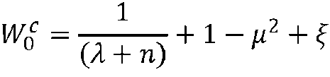

Con ^ siendo un parámetro utilizado para incorporar cualquier conocimiento previo de la distribución de la variable aleatoria aumentada xa.With ^ being a parameter used to incorporate any prior knowledge of the distribution of the augmented random variable xa.
La ganancia del filtro de Kalman, la estimación de estado y la matriz de covarianza en el tiempo k se pueden expresar entonces porThe gain of the Kalman filter, the state estimate, and the covariance matrix at time k can then be expressed by

puesto que x(k)=a, permitiendo estas ecuaciones determinar el exponente a de la ley de potencia, siendo este exponente variable en el tiempo.since x(k)=a, allowing these equations to determine the exponent a of the power law, this exponent being variable in time.
4) Determinación del perfil vertical de la velocidad del viento4) Determination of the vertical profile of the wind speed
Durante esta etapa, se determina el perfil vertical de la velocidad del viento flujo arriba del aerogenerador, poniendo en práctica el modelo de perfil vertical de la velocidad del viento construido en la etapa 2) con el exponente a determinado en la etapa 3). De este modo, el método según la invención permite determinar la velocidad del viento en cualquier punto del espacio flujo arriba del aerogenerador.During this stage, the vertical profile of the wind speed upstream of the wind turbine is determined, putting into practice the vertical profile model of the wind speed built in stage 2) with the exponent a determined in stage 3). Thus, the method according to the invention makes it possible to determine the wind speed at any point in space upstream of the wind turbine.
De manera preferente, el método, según la invención, puede permitir determinar la velocidad longitudinal del viento en cualquier punto del espacio flujo arriba del aerogenerador.Preferably, the method according to the invention can make it possible to determine the longitudinal speed of the wind at any point in space upstream of the wind turbine.
Según una forma de realización de la invención, se puede considerar en la ley de potencia la referencia z0 como la altitud de cualquier punto de medida del sensor LIDAR (que puede ser diferente de los puntos de medida utilizados durante la etapa 1)), y la velocidad vz0 la velocidad del viento medida en el punto de medida considerado. De este modo, el perfil vertical de la velocidad del viento se puede determinar en el plano de medida aplicando la ley de potencia.According to an embodiment of the invention, the reference z0 can be considered in the power law as the altitude of any measurement point of the lidar sensor (which can be different from the measurement points used during step 1)), and The speed vz0 is the wind speed measured at the measurement point considered. In this way, the vertical profile of the wind speed can be determined in the measurement plane by applying the power law.
De manera alternativa, se puede considerar en la ley de potencia, cualquier referencia z0 (por ejemplo, un punto en el plano del rotor) y la velocidad vz0 la velocidad del viento estimada (reconstruida) en el punto considerado. De este modo, se puede determinar la velocidad del viento en cualquier plano del espacio, incluso en el plano del rotor. Para reconstruir la velocidad del viento se puede aplicar cualquier método de reconstrucción del viento, en particular el descrito en la solicitud de patente FR 3068139 (WO2018/234409), cuyas etapas principales son:Alternatively, one can consider in the power law any reference z0 (for example, a point in the plane of the rotor) and the speed vz0 the estimated (reconstructed) wind speed at the point considered. In this way, the wind speed can be determined in any plane of space, even in the plane of the rotor. To reconstruct the wind speed, any wind reconstruction method can be applied, in particular the one described in patent application FR 3068139 (WO2018/234409), whose main stages are:
• Mallado del espacio ubicado flujo arriba de dicho sensor LIDAR, el mallado comprende puntos de estimación y puntos de medida;• Meshing of the space located upstream of said LIDAR sensor, the meshing includes estimation points and measurement points;
• Medida de la amplitud y de la dirección del viento en los diferentes puntos de medida;• Measurement of the amplitude and direction of the wind at the different measurement points;
• Estimación de la amplitud y de la dirección del viento en cualquier instante para todos los puntos de estimación por un método de mínimos cuadrados recursivos de una función de coste (también denominada función objetivo); y• Estimation of the amplitude and direction of the wind at any instant for all the estimation points by a method of recursive least squares of a cost function (also called objective function); Y
• Reconstrucción del campo de viento incidente en tres dimensiones y en tiempo real sobre todos los puntos discretizados.• Reconstruction of the incident wind field in three dimensions and in real time over all the discretized points.
La presente invención también se refiere a un método de control de un aerogenerador provisto de un sensor LIDAR. Para este método se ponen en práctica las etapas siguientes:The present invention also refers to a method of controlling a wind turbine provided with a LIDAR sensor. For this method the following steps are put into practice:
- se determina el perfil vertical de la velocidad del viento flujo arriba del aerogenerador mediante el método de determinación del perfil vertical de la velocidad del viento según cualquiera de las variantes descritas con anterioridad; y- the vertical profile of the wind speed upstream of the wind turbine is determined by means of the method for determining the vertical profile of the wind speed according to any of the previously described variants; Y
- se controla el aerogenerador según el perfil vertical de la velocidad del viento flujo arriba del aerogenerador. La predicción precisa y en tiempo real del perfil vertical de la velocidad del viento flujo arriba del aerogenerador permite un adecuado control del aerogenerador, en cuanto a minimizar los efectos sobre la estructura del aerogenerador y maximizar la potencia recuperada. En efecto, mediante este control, el sensor LIDAR permite anticipar la velocidad del viento que llegará al aerogenerador a partir de estas predicciones y así adaptar el equipamiento del aerogenerador con antelación de fase para que en el momento en el que llega el viento estimado, el aerogenerador esté en la configuración óptima para este viento. Por otro lado, el sensor LIDAR permite reducir las cargas sobre la estructura, de las cuales las palas y el mástil suponen el 54% del coste. En consecuencia, el uso de un sensor LIDAR permite optimizar la estructura del aerogenerador y, por tanto, reducir costes y mantenimiento.- the wind turbine is controlled according to the vertical profile of the wind speed upstream of the wind turbine. The accurate and real-time prediction of the vertical profile of the wind speed upstream of the wind turbine allows an adequate control of the wind turbine, in terms of minimizing the effects on the structure of the wind turbine and maximize recovered power. Indeed, by means of this control, the LIDAR sensor makes it possible to anticipate the speed of the wind that will reach the wind turbine based on these predictions and thus adapt the equipment of the wind turbine in advance of the phase so that at the moment in which the estimated wind arrives, the wind turbine is in the optimal configuration for this wind. On the other hand, the LIDAR sensor allows reducing the loads on the structure, of which the blades and the mast account for 54% of the cost. Consequently, the use of a LIDAR sensor makes it possible to optimize the structure of the wind turbine and, therefore, reduce costs and maintenance.
De conformidad con una puesta en práctica de la invención, es posible controlar el ángulo de inclinación de las palas y/o del par eléctrico de recuperación del generador del aerogenerador en función de la velocidad del viento. De manera preferible, se puede controlar el ángulo de inclinación individual de las palas. Se pueden utilizar otros tipos de dispositivos de regulación. El control de inclinación de las palas permite optimizar la recuperación de energía en función del viento que incide sobre las palas.In accordance with an implementation of the invention, it is possible to control the angle of inclination of the blades and/or of the recovery electrical torque of the generator of the wind turbine as a function of the wind speed. Preferably, the individual pitch angle of the blades can be controlled. Other types of regulating devices may be used. The blade inclination control allows optimizing the energy recovery depending on the wind that affects the blades.
Según una forma de realización de la invención, el ángulo de inclinación de las palas y/o el par eléctrico de recuperación se pueden determinar mediante cartografías del aerogenerador en función de la velocidad del viento a nivel del rotor. Por ejemplo, se puede aplicar el método de control descrito en la solicitud de patente FR 2976630 A1 (US 2012-0321463).According to an embodiment of the invention, the pitch angle of the blades and/or the recovery electrical torque can be determined by mapping the wind turbine as a function of the wind speed at rotor level. For example, the control method described in the patent application FR 2976630 A1 (US 2012-0321463) can be applied.
La Figura 3 ilustra, de forma esquemática y no limitativa, las etapas del método de control de un aerogenerador según una forma de realización de la invención. La primera etapa es una etapa de medida (MES) de la velocidad del viento v1, v2 en al menos un plano de medida a dos altitudes diferentes mediante el sensor LIDAR. Se construye un modelo de perfil vertical de la velocidad del viento (MOD). La siguiente etapa consiste en determinar el exponente a del modelo de perfil vertical de la velocidad del viento (MOD) mediante un filtro inoloro de Kalman (UKF) y medidas de velocidad del viento v1, v2. El exponente a determinado se utiliza con el modelo del perfil vertical de la velocidad del viento (MOD) para determinar (PRO) el perfil vertical de la velocidad del viento v(z). El perfil vertical de la velocidad del viento v(z) se utiliza entonces para realizar el control (CON) del aerogenerador.Figure 3 illustrates, in a schematic and non-limiting way, the steps of the control method of a wind turbine according to an embodiment of the invention. The first stage is a measurement stage (MES) of the wind speed v1, v2 in at least one measurement plane at two different altitudes by means of the LIDAR sensor. A vertical profile model of the wind speed (MOD) is built. The next step is to determine the exponent a of the vertical profile model of wind speed (MOD) using a Kalman odorless filter (UKF) and wind speed measurements v1, v2. The determined exponent a is used with the vertical wind speed profile (MOD) model to determine (PRO) the vertical wind speed profile v(z). The vertical profile of the wind speed v(z) is then used to carry out the control (CON) of the wind turbine.
Además, la invención se refiere a un producto programa informático, que comprende instrucciones codificadas dispuestas para poner en práctica las etapas de uno de los métodos descritos con anterioridad (método de determinación del perfil vertical de la velocidad del viento, método de control). El programa se ejecuta en una unidad de procesamiento del sensor LIDAR, o en cualquier medio análogo, vinculado al sensor LIDAR o al aerogenerador. Furthermore, the invention relates to a computer program product, comprising coded instructions arranged to implement the steps of one of the methods described above (method for determining the vertical profile of wind speed, control method). The program runs on a lidar sensor processing unit, or on any analogous media, linked to the lidar sensor or wind turbine.
Según un aspecto, la presente invención también se refiere a un sensor LIDAR para un aerogenerador, que comprende una unidad de procesamiento configurada para poner en práctica uno de los métodos descritos con anterioridad (método de determinación del perfil vertical de la velocidad del viento, método de control).According to one aspect, the present invention also relates to a LIDAR sensor for a wind turbine, comprising a processing unit configured to implement one of the previously described methods (wind speed vertical profile determination method, wind speed vertical profile determination method, of control).
De conformidad con una puesta en práctica de la invención, el sensor LIDAR puede ser un sensor LIDAR escaneado, LIDAR continuo o LIDAR pulsado. De manera preferible, el sensor LIDAR es un sensor LIDAR pulsado.In accordance with one implementation of the invention, the LIDAR sensor may be a scanned LIDAR, continuous LIDAR, or pulsed LIDAR sensor. Preferably, the LIDAR sensor is a pulsed LIDAR sensor.
La invención también se refiere a un aerogenerador, en particular un aerogenerador en offshore (en alta mar) u en onshore (en tierra) provisto con un sensor LIDAR tal como se describió con anterioridad. Según una forma de realización de la invención, el sensor LIDAR puede estar dispuesto en la barquilla del aerogenerador o en el cono frontal del aerogenerador. El sensor LIDAR está orientado para tomar una medida del viento flujo arriba del aerogenerador (es decir antes del aerogenerador y según su eje longitudinal, designado por el eje x en la Figura 1). Según una forma de realización, el aerogenerador puede adaptarse al aerogenerador ilustrado en la Figura 1.The invention also relates to a wind turbine, in particular an offshore (offshore) or onshore (onshore) wind turbine provided with a LIDAR sensor as described above. According to an embodiment of the invention, the LIDAR sensor can be arranged in the nacelle of the wind turbine or in the frontal cone of the wind turbine. The LIDAR sensor is oriented to take a measurement of the wind upstream of the wind turbine (that is, before the wind turbine and along its longitudinal axis, designated by the x -axis in Figure 1). According to one embodiment, the wind turbine can be adapted to the wind turbine illustrated in Figure 1.
Para la forma de realización del método de control, el aerogenerador puede comprender medios de control, por ejemplo, el control del ángulo de inclinación (que se puede traducirse como ángulo de cabeceo) de al menos una pala del aerogenerador o el control del par eléctrico, para poner en práctica el método de control según la invención. For the embodiment of the control method, the wind turbine may comprise control means, for example, the control of the pitch angle (which can be translated as pitch angle) of at least one blade of the wind turbine or the control of the electrical torque , to implement the control method according to the invention.
Ejemplosexamples
Las características y ventajas del método, según la invención, aparecerán más claramente con la lectura del ejemplo de aplicación siguiente.The characteristics and advantages of the method according to the invention will appear more clearly on reading the following application example.
Para este ejemplo, la velocidad del viento estimada en un punto flujo arriba del aerogenerador se compara con el perfil vertical de la velocidad del viento determinado por el método según una forma de realización de la invención. Para ello, para una distancia de 200 m flujo arriba del aerogenerador, se miden las velocidades del viento en dos puntos de medida a diferentes altitudes para estimar, en tiempo real, el exponente a de la ley de potencia, mediante el método según una forma de realización de la invención A continuación, para una distancia de 100 m flujo arriba del aerogenerador, se aplica el perfil vertical de la velocidad del viento determinado con el exponente a para determinar la velocidad longitudinal del viento a una altitud predeterminada mediante una medida de la velocidad longitudinal del viento a una altura conocida.For this example, the estimated wind speed at a point upstream of the wind turbine is compared to the vertical wind speed profile determined by the method according to an embodiment of the invention. To do this, for a distance of 200 m upstream from the wind turbine, the wind speeds are measured at two measurement points at different altitudes to estimate, in real time, the exponent a of the power law, using the method according to a form of carrying out the invention Next, for a distance of 100 m upstream of the wind turbine, the vertical profile of the wind speed determined with the exponent a is applied to determine the longitudinal wind speed at a predetermined altitude by means of a measurement of the longitudinal wind speed at a known height.
Para este ejemplo, se considera un sensor LIDAR pulsado de 4 haces que realiza medidas en planos de medida ubicados a 100 y 200 m del aerogenerador. For this example, a 4-beam pulsed LIDAR sensor is considered that performs measurements in measurement planes located 100 and 200 m from the wind turbine.
La Figura 4 representa la velocidad radial del viento RWS en m/s (es decir, según la dirección del haz de medida) medida para dos puntos de medida (que pueden corresponder a los puntos de medida PT1 y PT3 de la Figura 1) en función de tiempo T en 104s para un día de medida. Esta velocidad radial del viento se mide en un plano de medida de 200 m flujo arriba del aerogenerador. La velocidad medida v1 en gris claro corresponde a la velocidad medida a la velocidad del punto de medida más bajo. La velocidad medida v2 en gris oscuro corresponde a la velocidad medida a la velocidad del punto de medida más alto. Como era de esperar, la velocidad medida en el punto de medida más alto es mayor que la velocidad medida en el punto de medida más bajo. En esta figura se puede constatar que el sensor LIDAR no proporciona medidas en cualquier momento, debido a un efecto de bloqueo de las palas.Figure 4 represents the radial wind velocity RWS in m/s (i.e. according to the direction of the measurement beam) measured for two measurement points (which may correspond to measurement points PT1 and PT3 in Figure 1) at function of time T in 104s for one measurement day. This radial wind speed is measured in a measurement plane 200 m upstream of the wind turbine. The measured speed v1 in light gray corresponds to the measured speed at the speed of the lowest measuring point. The measured velocity v2 in dark gray corresponds to the measured velocity at the velocity of the highest measurement point. As expected, the speed measured at the highest measurement point is greater than the speed measured at the lowest measurement point. In this figure it can be seen that the LIDAR sensor does not provide measurements at any time, due to a blocking effect of the blades.
La Figura 5 es una curva de la velocidad longitudinal del viento wx en m/s (es decir, según la dirección x de la Figura 1) en función del tiempo T en 104s, correspondiente a un día de medida. La velocidad longitudinal del viento wx se estima a partir de la velocidad radial del viento RWS de la Figura 4. Esta velocidad longitudinal se estima en un plano de medida de 200 m flujo arriba del aerogenerador. La velocidad longitudinal wx1 en gris claro corresponde a la velocidad longitudinal estimada en el punto de medida más bajo. La velocidad longitudinal wx2 en gris oscuro corresponde a la velocidad longitudinal estimada en el punto de medida más alto.Figure 5 is a curve of the longitudinal wind speed wx in m/s (that is, according to the x direction of Figure 1) as a function of time T in 104s, corresponding to one measurement day. The longitudinal wind speed wx is estimated from the radial wind speed RWS in Figure 4. This longitudinal speed is estimated at a measurement plane 200 m upstream of the wind turbine. The longitudinal velocity wx1 in light gray corresponds to the estimated longitudinal velocity at the lowest measurement point. The longitudinal velocity wx2 in dark gray corresponds to the estimated longitudinal velocity at the highest measurement point.
A partir de estas velocidades, se determina por medio del método según la invención el exponente a de la ley de potencia. La Figura 6 es una curva del exponente a de la ley de potencia en función del tiempo T en 104s. Se puede constatar que el exponente a varía de manera significativa, por lo que el supuesto de la técnica anterior que considera un exponente a constante no es realista y no permite determinar con precisión el perfil vertical de la velocidad del viento.From these speeds, the exponent a of the power law is determined by means of the method according to the invention. Figure 6 is a curve of the exponent a of the power law as a function of time T in 104s. It can be seen that the exponent a varies significantly, so the assumption of the prior art that considers an exponent a constant is unrealistic and does not allow the vertical profile of the wind speed to be accurately determined.
El sensor LIDAR también mide la velocidad del viento en el plano de medida ubicado 100 m flujo arriba del aerogenerador a dos altitudes conocidas. Para mostrar la naturaleza precisa del método, según la invención, por un lado, se toma como referencia la medida de la velocidad del viento en el punto más alto a 100 m y, por otro lado, se estima la velocidad del viento, en el punto de medida más alto, a 100 m mediante el método según la invención a partir de la velocidad del viento en el punto de medida más bajo a 100 m y del exponente a determinado en la Figura 6 con las medidas de la velocidad del viento a 200 m. La Figura 7 es una curva de la velocidad longitudinal del viento wx en m/s (es decir, según la dirección x de la Figura 1) en el punto de medida más alto en función del tiempo T en 104s. Esta velocidad longitudinal se estima en un plano de medida 100 m flujo arriba del aerogenerador. La curva REF corresponde a la referencia definida con anterioridad, y la curva EST corresponde a la estimación mediante el método según la invención tal como se definió con anterioridad. Se observa que las curvas son muy próximas, lo que demuestra que el método, según la invención, permite una determinación precisa de la velocidad del viento. The LIDAR sensor also measures the wind speed at the measurement plane located 100 m upstream of the wind turbine at two known altitudes. To show the precise nature of the method, according to the invention, on the one hand, the measurement of the wind speed at the highest point at 100 m is taken as a reference and, on the other hand, the wind speed is estimated, at the point highest measurement point, at 100 m using the method according to the invention from the wind speed at the lowest measurement point at 100 m and from the exponent a determined in Figure 6 with the measurements of the wind speed at 200 m . Figure 7 is a curve of the longitudinal wind speed wx in m/s (ie according to the x direction of Figure 1) at the highest measurement point as a function of time T in 104s. This longitudinal velocity is estimated on a measurement plane 100 m upstream of the wind turbine. The REF curve corresponds to the previously defined reference, and the EST curve corresponds to the estimation by the method according to the invention as previously defined. It is observed that the curves are very close, which shows that the method, according to the invention, allows a precise determination of the wind speed.
Claims (9)


Applications Claiming Priority (1)
| Application Number | Priority Date | Filing Date | Title |
|---|---|---|---|
| FR1906569A FR3097644B1 (en) | 2019-06-19 | 2019-06-19 | Method for determining the vertical profile of the wind speed upstream of a wind turbine equipped with a laser remote sensing sensor |
Publications (1)
| Publication Number | Publication Date |
|---|---|
| ES2928697T3 true ES2928697T3 (en) | 2022-11-22 |
Family
ID=67957111
Family Applications (1)
| Application Number | Title | Priority Date | Filing Date |
|---|---|---|---|
| ES20178434T Active ES2928697T3 (en) | 2019-06-19 | 2020-06-05 | Method for determining the vertical profile of the wind speed upstream of a wind turbine equipped with a laser remote sensing sensor |
Country Status (7)
| Country | Link |
|---|---|
| US (1) | US11454725B2 (en) |
| EP (1) | EP3754341B1 (en) |
| CN (1) | CN112114332B (en) |
| CA (1) | CA3083653A1 (en) |
| DK (1) | DK3754341T3 (en) |
| ES (1) | ES2928697T3 (en) |
| FR (1) | FR3097644B1 (en) |
Families Citing this family (7)
| Publication number | Priority date | Publication date | Assignee | Title |
|---|---|---|---|---|
| WO2020260625A1 (en) * | 2019-06-28 | 2020-12-30 | Aalto University Foundation Sr | Quantitative raman spectroscopy |
| US11294063B2 (en) * | 2020-04-02 | 2022-04-05 | Mitsubishi Electric Research Laboratories, Inc. | System and method for fast wind flow measurement by LiDAR in a complex terrain |
| FR3114881B1 (en) * | 2020-10-01 | 2022-09-09 | Ifp Energies Now | Method for determining the average wind speed using a laser remote sensing sensor |
| FR3116123B1 (en) * | 2020-11-06 | 2022-10-14 | Ifp Energies Now | Method for determining the wind speed in the plane of the rotor of a wind turbine |
| EP4122810A1 (en) * | 2021-07-20 | 2023-01-25 | Ørsted Wind Power A/S | Floating vertical wind profile sensor device and method of determining a vertical wind profile |
| FR3126248B1 (en) | 2021-08-20 | 2023-07-28 | Ifp Energies Now | Method for determining wind speed using a laser remote sensing sensor mounted on a wind turbine |
| CN114233580B (en) * | 2021-12-01 | 2023-11-21 | 三一重能股份有限公司 | A method and device for correcting wind speed in wind turbine cabin |
Family Cites Families (13)
| Publication number | Priority date | Publication date | Assignee | Title |
|---|---|---|---|---|
| FR2976630B1 (en) | 2011-06-17 | 2021-07-23 | Ifp Energies Now | PROCESS FOR OPTIMIZING THE POWER RECOVERED BY A WIND TURBINE BY REDUCING THE MECHANICAL IMPACT ON THE STRUCTURE. |
| EP2581761B1 (en) * | 2011-10-14 | 2017-08-23 | Vestas Wind Systems A/S | Estimation of Wind Properties Using a Light Detection and Ranging Device |
| FR3013777B1 (en) | 2013-11-25 | 2015-11-13 | IFP Energies Nouvelles | METHOD OF MONITORING AND MONITORING A WIND TURBINE USING WIND SPEED ESTIMATION USING A LIDAR SENSOR |
| ES2537476B1 (en) * | 2013-12-04 | 2016-03-23 | Acciona Windpower, S.A. | Wind turbine control system and method |
| JP6328347B2 (en) * | 2015-10-23 | 2018-05-23 | 三菱電機株式会社 | Wind measuring device |
| CN108369276A (en) * | 2015-12-10 | 2018-08-03 | 三菱电机株式会社 | LiDAR device |
| EP3440347B1 (en) * | 2016-04-08 | 2021-06-02 | Vestas Wind Systems A/S | Control of a wind turbine comprising multi-axial accelerometers |
| US10247170B2 (en) * | 2016-06-07 | 2019-04-02 | General Electric Company | System and method for controlling a dynamic system |
| US10539116B2 (en) * | 2016-07-13 | 2020-01-21 | General Electric Company | Systems and methods to correct induction for LIDAR-assisted wind turbine control |
| FR3068139B1 (en) | 2017-06-21 | 2019-12-20 | IFP Energies Nouvelles | PROCESS FOR ACQUISITION AND MODELING BY AN LIDAR SENSOR OF AN INCIDENT WIND FIELD |
| WO2020096560A1 (en) * | 2018-11-05 | 2020-05-14 | General Electric Company | Power system measurement based model calibration with enhanced optimization |
| CN111766397B (en) * | 2020-06-19 | 2022-06-10 | 北京航空航天大学合肥创新研究院 | Meteorological wind measurement method based on inertia/satellite/atmosphere combination |
| CN114802616B (en) * | 2022-04-15 | 2023-08-04 | 浙江科技学院 | Small water surface cleaning unmanned boat and its control method and positioning method |
-
2019
- 2019-06-19 FR FR1906569A patent/FR3097644B1/en not_active Expired - Fee Related
-
2020
- 2020-06-05 ES ES20178434T patent/ES2928697T3/en active Active
- 2020-06-05 EP EP20178434.5A patent/EP3754341B1/en active Active
- 2020-06-05 DK DK20178434.5T patent/DK3754341T3/en active
- 2020-06-15 CA CA3083653A patent/CA3083653A1/en active Pending
- 2020-06-18 CN CN202010559123.4A patent/CN112114332B/en active Active
- 2020-06-19 US US16/906,105 patent/US11454725B2/en active Active
Also Published As
| Publication number | Publication date |
|---|---|
| CA3083653A1 (en) | 2020-12-19 |
| US20200400836A1 (en) | 2020-12-24 |
| FR3097644A1 (en) | 2020-12-25 |
| FR3097644B1 (en) | 2021-06-11 |
| EP3754341A1 (en) | 2020-12-23 |
| CN112114332B (en) | 2025-10-10 |
| EP3754341B1 (en) | 2022-08-10 |
| DK3754341T3 (en) | 2022-11-07 |
| US11454725B2 (en) | 2022-09-27 |
| CN112114332A (en) | 2020-12-22 |
Similar Documents
| Publication | Publication Date | Title |
|---|---|---|
| ES2928697T3 (en) | Method for determining the vertical profile of the wind speed upstream of a wind turbine equipped with a laser remote sensing sensor | |
| ES2919049T3 (en) | Acquisition method and modeling of an incident wind field using a LiDAR sensor | |
| ES2882299T3 (en) | Procedure for determining an induction factor for a wind turbine from a laser remote sensing sensor | |
| Fuertes et al. | 3D turbulence measurements using three synchronous wind lidars: Validation against sonic anemometry | |
| US9234506B2 (en) | Estimation of wind properties using a light detection and ranging device | |
| Arnqvist et al. | Wind statistics from a forested landscape | |
| EP2588753B1 (en) | Apparatus and method for reducing yaw error in wind turbines | |
| ES2953717T3 (en) | Wind speed prediction procedure in the rotor plane for a wind turbine equipped with a laser remote sensing sensor | |
| EP2581761B1 (en) | Estimation of Wind Properties Using a Light Detection and Ranging Device | |
| ES2958290T3 (en) | Induction controlled wind turbine | |
| Bradley et al. | Remote sensing winds in complex terrain—A review | |
| Bergström et al. | Wind power in forests: wind and effects on loads | |
| SJ et al. | Spatial averaging-effects on turbulence measured by a continuous-wave coherent lidar | |
| Newman et al. | An error reduction algorithm to improve lidar turbulence estimates for wind energy | |
| US20170167470A1 (en) | Methods and systems for controlling a wind turbine | |
| ES2967326T3 (en) | Method for determining wind direction using a laser remote sensing sensor | |
| ES2967632T3 (en) | Procedure to determine the wind speed in the plane of the rotor of a wind turbine | |
| Iungo et al. | Measurement procedures for characterization of wind turbine wakes with scanning Doppler wind LiDARs | |
| ES2970376T3 (en) | Method for determining average wind speed using a laser remote sensing sensor | |
| Barthelmie et al. | Best practice for measuring wind speeds and turbulence offshore through in-situ and remote sensing technologies | |
| Mohr et al. | Wind power in forests II: Forest wind | |
| Shin et al. | Characteristics analysis and reliability verification of nacelle lidar measurements | |
| Tumenbayar et al. | Experimental investigation on power performance testing using nacelle lidar measurements over excavated terrain | |
| ES2967063T3 (en) | Procedure to determine an induction factor between a measurement plane and the rotor plane of a wind turbine | |
| ES2927113T3 (en) | Procedures and systems to control a wind turbine |