ES2934005T3 - Systems and methods to detect and evaluate oscillations in an electrical network - Google Patents
Systems and methods to detect and evaluate oscillations in an electrical network Download PDFInfo
- Publication number
- ES2934005T3 ES2934005T3 ES18190469T ES18190469T ES2934005T3 ES 2934005 T3 ES2934005 T3 ES 2934005T3 ES 18190469 T ES18190469 T ES 18190469T ES 18190469 T ES18190469 T ES 18190469T ES 2934005 T3 ES2934005 T3 ES 2934005T3
- Authority
- ES
- Spain
- Prior art keywords
- oscillation
- digital data
- frequency band
- frequency
- electrical network
- Prior art date
- Legal status (The legal status is an assumption and is not a legal conclusion. Google has not performed a legal analysis and makes no representation as to the accuracy of the status listed.)
- Active
Links
Classifications
-
- G—PHYSICS
- G01—MEASURING; TESTING
- G01R—MEASURING ELECTRIC VARIABLES; MEASURING MAGNETIC VARIABLES
- G01R19/00—Arrangements for measuring currents or voltages or for indicating presence or sign thereof
- G01R19/25—Arrangements for measuring currents or voltages or for indicating presence or sign thereof using digital measurement techniques
- G01R19/2513—Arrangements for monitoring electric power systems, e.g. power lines or loads; Logging
-
- G—PHYSICS
- G01—MEASURING; TESTING
- G01R—MEASURING ELECTRIC VARIABLES; MEASURING MAGNETIC VARIABLES
- G01R23/00—Arrangements for measuring frequencies; Arrangements for analysing frequency spectra
- G01R23/02—Arrangements for measuring frequency, e.g. pulse repetition rate; Arrangements for measuring period of current or voltage
-
- G—PHYSICS
- G01—MEASURING; TESTING
- G01R—MEASURING ELECTRIC VARIABLES; MEASURING MAGNETIC VARIABLES
- G01R19/00—Arrangements for measuring currents or voltages or for indicating presence or sign thereof
- G01R19/25—Arrangements for measuring currents or voltages or for indicating presence or sign thereof using digital measurement techniques
- G01R19/2506—Arrangements for conditioning or analysing measured signals, e.g. for indicating peak values ; Details concerning sampling, digitizing or waveform capturing
-
- G—PHYSICS
- G01—MEASURING; TESTING
- G01R—MEASURING ELECTRIC VARIABLES; MEASURING MAGNETIC VARIABLES
- G01R19/00—Arrangements for measuring currents or voltages or for indicating presence or sign thereof
- G01R19/25—Arrangements for measuring currents or voltages or for indicating presence or sign thereof using digital measurement techniques
- G01R19/257—Arrangements for measuring currents or voltages or for indicating presence or sign thereof using digital measurement techniques using analogue/digital converters of the type with comparison of different reference values with the value of voltage or current, e.g. using step-by-step method
-
- G—PHYSICS
- G01—MEASURING; TESTING
- G01R—MEASURING ELECTRIC VARIABLES; MEASURING MAGNETIC VARIABLES
- G01R25/00—Arrangements for measuring phase angle between a voltage and a current or between voltages or currents
-
- G—PHYSICS
- G01—MEASURING; TESTING
- G01R—MEASURING ELECTRIC VARIABLES; MEASURING MAGNETIC VARIABLES
- G01R27/00—Arrangements for measuring resistance, reactance, impedance, or electric characteristics derived therefrom
- G01R27/28—Measuring attenuation, gain, phase shift or derived characteristics of electric four pole networks, i.e. two-port networks; Measuring transient response
-
- H—ELECTRICITY
- H02—GENERATION; CONVERSION OR DISTRIBUTION OF ELECTRIC POWER
- H02J—ELECTRIC POWER NETWORKS; CIRCUIT ARRANGEMENTS OR SYSTEMS FOR SUPPLYING OR DISTRIBUTING ELECTRIC POWER; SYSTEMS FOR STORING ELECTRIC ENERGY
- H02J13/00—Circuit arrangements for providing remote monitoring or remote control of equipment in a power distribution network
- H02J13/12—Monitoring network conditions, e.g. electrical magnitudes or operational status
-
- H—ELECTRICITY
- H02—GENERATION; CONVERSION OR DISTRIBUTION OF ELECTRIC POWER
- H02J—ELECTRIC POWER NETWORKS; CIRCUIT ARRANGEMENTS OR SYSTEMS FOR SUPPLYING OR DISTRIBUTING ELECTRIC POWER; SYSTEMS FOR STORING ELECTRIC ENERGY
- H02J13/00—Circuit arrangements for providing remote monitoring or remote control of equipment in a power distribution network
- H02J13/13—Circuit arrangements for providing remote monitoring or remote control of equipment in a power distribution network characterised by the transmission of data to equipment in the power network
- H02J13/1331—Circuit arrangements for providing remote monitoring or remote control of equipment in a power distribution network characterised by the transmission of data to equipment in the power network using wireless data transmission
-
- H—ELECTRICITY
- H02—GENERATION; CONVERSION OR DISTRIBUTION OF ELECTRIC POWER
- H02J—ELECTRIC POWER NETWORKS; CIRCUIT ARRANGEMENTS OR SYSTEMS FOR SUPPLYING OR DISTRIBUTING ELECTRIC POWER; SYSTEMS FOR STORING ELECTRIC ENERGY
- H02J3/00—Circuit arrangements for AC mains or AC distribution networks
-
- H—ELECTRICITY
- H02—GENERATION; CONVERSION OR DISTRIBUTION OF ELECTRIC POWER
- H02J—ELECTRIC POWER NETWORKS; CIRCUIT ARRANGEMENTS OR SYSTEMS FOR SUPPLYING OR DISTRIBUTING ELECTRIC POWER; SYSTEMS FOR STORING ELECTRIC ENERGY
- H02J3/00—Circuit arrangements for AC mains or AC distribution networks
- H02J3/001—Arrangements for handling faults or abnormalities, e.g. emergencies or contingencies
- H02J3/0014—Arrangements for handling faults or abnormalities, e.g. emergencies or contingencies for preventing or reducing power oscillations in networks
-
- Y—GENERAL TAGGING OF NEW TECHNOLOGICAL DEVELOPMENTS; GENERAL TAGGING OF CROSS-SECTIONAL TECHNOLOGIES SPANNING OVER SEVERAL SECTIONS OF THE IPC; TECHNICAL SUBJECTS COVERED BY FORMER USPC CROSS-REFERENCE ART COLLECTIONS [XRACs] AND DIGESTS
- Y02—TECHNOLOGIES OR APPLICATIONS FOR MITIGATION OR ADAPTATION AGAINST CLIMATE CHANGE
- Y02E—REDUCTION OF GREENHOUSE GAS [GHG] EMISSIONS, RELATED TO ENERGY GENERATION, TRANSMISSION OR DISTRIBUTION
- Y02E40/00—Technologies for an efficient electrical power generation, transmission or distribution
- Y02E40/70—Smart grids as climate change mitigation technology in the energy generation sector
-
- Y—GENERAL TAGGING OF NEW TECHNOLOGICAL DEVELOPMENTS; GENERAL TAGGING OF CROSS-SECTIONAL TECHNOLOGIES SPANNING OVER SEVERAL SECTIONS OF THE IPC; TECHNICAL SUBJECTS COVERED BY FORMER USPC CROSS-REFERENCE ART COLLECTIONS [XRACs] AND DIGESTS
- Y04—INFORMATION OR COMMUNICATION TECHNOLOGIES HAVING AN IMPACT ON OTHER TECHNOLOGY AREAS
- Y04S—SYSTEMS INTEGRATING TECHNOLOGIES RELATED TO POWER NETWORK OPERATION, COMMUNICATION OR INFORMATION TECHNOLOGIES FOR IMPROVING THE ELECTRICAL POWER GENERATION, TRANSMISSION, DISTRIBUTION, MANAGEMENT OR USAGE, i.e. SMART GRIDS
- Y04S10/00—Systems supporting electrical power generation, transmission or distribution
- Y04S10/22—Flexible AC transmission systems [FACTS] or power factor or reactive power compensating or correcting units
-
- Y—GENERAL TAGGING OF NEW TECHNOLOGICAL DEVELOPMENTS; GENERAL TAGGING OF CROSS-SECTIONAL TECHNOLOGIES SPANNING OVER SEVERAL SECTIONS OF THE IPC; TECHNICAL SUBJECTS COVERED BY FORMER USPC CROSS-REFERENCE ART COLLECTIONS [XRACs] AND DIGESTS
- Y04—INFORMATION OR COMMUNICATION TECHNOLOGIES HAVING AN IMPACT ON OTHER TECHNOLOGY AREAS
- Y04S—SYSTEMS INTEGRATING TECHNOLOGIES RELATED TO POWER NETWORK OPERATION, COMMUNICATION OR INFORMATION TECHNOLOGIES FOR IMPROVING THE ELECTRICAL POWER GENERATION, TRANSMISSION, DISTRIBUTION, MANAGEMENT OR USAGE, i.e. SMART GRIDS
- Y04S10/00—Systems supporting electrical power generation, transmission or distribution
- Y04S10/30—State monitoring, e.g. fault, temperature monitoring, insulator monitoring, corona discharge
-
- Y—GENERAL TAGGING OF NEW TECHNOLOGICAL DEVELOPMENTS; GENERAL TAGGING OF CROSS-SECTIONAL TECHNOLOGIES SPANNING OVER SEVERAL SECTIONS OF THE IPC; TECHNICAL SUBJECTS COVERED BY FORMER USPC CROSS-REFERENCE ART COLLECTIONS [XRACs] AND DIGESTS
- Y04—INFORMATION OR COMMUNICATION TECHNOLOGIES HAVING AN IMPACT ON OTHER TECHNOLOGY AREAS
- Y04S—SYSTEMS INTEGRATING TECHNOLOGIES RELATED TO POWER NETWORK OPERATION, COMMUNICATION OR INFORMATION TECHNOLOGIES FOR IMPROVING THE ELECTRICAL POWER GENERATION, TRANSMISSION, DISTRIBUTION, MANAGEMENT OR USAGE, i.e. SMART GRIDS
- Y04S40/00—Systems for electrical power generation, transmission, distribution or end-user application management characterised by the use of communication or information technologies, or communication or information technology specific aspects supporting them
- Y04S40/12—Systems for electrical power generation, transmission, distribution or end-user application management characterised by the use of communication or information technologies, or communication or information technology specific aspects supporting them characterised by data transport means between the monitoring, controlling or managing units and monitored, controlled or operated electrical equipment
- Y04S40/126—Systems for electrical power generation, transmission, distribution or end-user application management characterised by the use of communication or information technologies, or communication or information technology specific aspects supporting them characterised by data transport means between the monitoring, controlling or managing units and monitored, controlled or operated electrical equipment using wireless data transmission
Landscapes
- Engineering & Computer Science (AREA)
- Power Engineering (AREA)
- Physics & Mathematics (AREA)
- General Physics & Mathematics (AREA)
- Remote Monitoring And Control Of Power-Distribution Networks (AREA)
- Supply And Distribution Of Alternating Current (AREA)
- Measurement Of Mechanical Vibrations Or Ultrasonic Waves (AREA)
- Measuring Frequencies, Analyzing Spectra (AREA)
Abstract
Varias realizaciones descritas en esta divulgación pertenecen a métodos y sistemas para detectar y evaluar oscilaciones en una red de energía eléctrica (110). Las oscilaciones pueden incluir una o más condiciones oscilatorias, que pueden ocurrir en una o más de cinco bandas de frecuencia predefinidas. Cada una de las cinco bandas de frecuencia predefinidas está categorizada, al menos en parte, por oscilaciones que se originan por fuentes únicas y diferentes. En una realización, se puede usar un detector de oscilación (145) para detectar la condición oscilatoria y determinar una característica de magnitud, una característica de fase y/o una característica de amortiguamiento de al menos una frecuencia de oscilación que contribuye a la condición oscilatoria. (Traducción automática con Google Translate, sin valor legal)Various embodiments described in this disclosure pertain to methods and systems for detecting and evaluating oscillations in an electrical power network (110). Oscillations may include one or more oscillatory conditions, which may occur in one or more of five predefined frequency bands. Each of the five predefined frequency bands is categorized, at least in part, by oscillations that originate from unique and different sources. In one embodiment, an oscillation detector (145) may be used to detect the oscillatory condition and determine a magnitude characteristic, a phase characteristic, and/or a damping characteristic of at least one oscillation frequency that contributes to the oscillatory condition. . (Automatic translation with Google Translate, without legal value)
Description
DESCRIPCIÓNDESCRIPTION
Sistemas y métodos para detectar y evaluar oscilaciones en una red eléctricaSystems and methods to detect and evaluate oscillations in an electrical network
Sector técnico de la invenciónTechnical sector of the invention
Esta invención se refiere, en general, a la detección de oscilaciones y, más particularmente, a sistemas y métodos para detectar y evaluar oscilaciones en una red eléctrica.This invention relates generally to oscillation detection and more particularly to systems and methods for detecting and evaluating oscillations in an electrical network.
Antecedentes de la invenciónBackground of the invention
Una red eléctrica generalmente incluye varios componentes, como líneas de transmisión, torres, generadores de energía eléctrica, transformadores y disyuntores, que se instalan en una gran área geográfica. En el extremo del cliente de la red eléctrica, una amplia variedad de elementos, como elementos de iluminación (por ejemplo, bombillas y artefactos de iluminación), elementos de calefacción/refrigeración (por ejemplo, calefactores y acondicionadores de aire) y equipos industriales (por ejemplo, motores eléctricos y maquinaria eléctrica) funcionan como una carga diversa y distribuida que extrae energía a través de la red eléctrica. Los diversos componentes que constituyen la red eléctrica y los diversos componentes que constituyen la carga en la red eléctrica están sujetos a diversas fuerzas eléctricas, mecánicas, electromecánicas y ambientales que pueden conducir a estados oscilatorios indeseables.An electrical network generally includes several components, such as transmission lines, towers, electric power generators, transformers, and circuit breakers, that are installed over a large geographic area. At the customer end of the electrical grid, a wide variety of items such as lighting fixtures (for example, light bulbs and light fixtures), heating/cooling elements (for example, heaters and air conditioners), and industrial equipment ( for example, electric motors and electrical machinery) function as a diverse, distributed load that draws power from the electrical grid. The various components that make up the power grid and the various components that make up the load in the power grid are subject to various electrical, mechanical, electromechanical, and environmental forces that can lead to undesirable oscillatory states.
Por ejemplo, se puede crear un tipo de oscilación en una línea de transmisión de energía debido a la oscilación de un rotor en un generador de energía eléctrica. Se puede crear otro tipo de oscilación en una línea de transmisión de energía debido a transitorios de conmutación u otras anomalías eléctricas generadas, por ejemplo, por una fuente de alimentación de conmutación que tiene un modo de operación de conmutación. Se puede crear otro tipo más de oscilación en una línea de transmisión de energía debido a la naturaleza de la impedancia (inductancia distribuida y capacitancia distribuida) presentada por la línea de transmisión de energía a un generador de energía eléctrica, por ejemplo.For example, a type of oscillation can be created in a power transmission line due to the oscillation of a rotor in an electrical power generator. Another type of oscillation can be created in a power transmission line due to switching transients or other electrical anomalies generated, for example, by a switching power supply having a switching mode of operation. Yet another type of oscillation can be created in a power transmission line due to the nature of the impedance (distributed inductance and distributed capacitance) presented by the power transmission line to an electrical power generator, for example.
Algunas de estas oscilaciones indeseables se amortiguan automáticamente y no tienen un impacto significativo en las operaciones. Sin embargo, algunos otros tipos de oscilaciones, como las causadas por líneas de transmisión de energía muy largas, dispositivos que contienen electrónica de potencia y generadores síncronos que interactúan entre sí, pueden provocar inestabilidades operativas y daños en varios componentes de la red eléctrica. Tales oscilaciones indeseables pueden tener efectos adversos sobre la red eléctrica y los componentes acoplados a la red eléctrica. Some of these undesirable oscillations are automatically damped and do not have a significant impact on operations. However, some other types of oscillations, such as those caused by very long power transmission lines, devices containing power electronics, and synchronous generators interacting with each other, can cause operational instabilities and damage to various components of the power grid. Such undesirable oscillations can have adverse effects on the electrical network and components coupled to the electrical network.
La patente WO 2005/088802 A1 da a conocer un dispositivo para la prevención de fallos graves en redes de suministro eléctrico mediante análisis espectral de la tensión de la red.The patent WO 2005/088802 A1 discloses a device for the prevention of serious failures in electricity supply networks by means of spectral analysis of the network voltage.
Breve descripción de la invenciónBrief description of the invention
Las realizaciones de la invención están dirigidas, en general, a sistemas para detectar y evaluar oscilaciones en una red eléctrica. La invención se define en la reivindicación.Embodiments of the invention are directed, in general, to systems for detecting and evaluating oscillations in an electrical network. The invention is defined in the claim.
Breve descripción de los dibujosBrief description of the drawings
Habiéndose descrito así la invención en términos generales, a continuación se hará referencia a los dibujos adjuntos, que no están necesariamente dibujados a escala, y en los que:The invention having thus been described in general terms, reference will now be made to the accompanying drawings, which are not necessarily drawn to scale, and in which:
la figura 1 ilustra un sistema de monitorización de oscilaciones acoplado a una red eléctrica, de acuerdo con una realización a modo de ejemplo de la invención.Figure 1 illustrates a oscillation monitoring system coupled to a power grid, in accordance with an exemplary embodiment of the invention.
la figura 2 ilustra algunos elementos a modo de ejemplo que pueden incluirse en el sistema de monitorización de oscilaciones mostrado en la figura 1.Figure 2 illustrates some exemplary elements that may be included in the oscillation monitoring system shown in Figure 1.
la figura 3 ilustra algunos elementos de ejemplo que se pueden utilizar para la extracción de envolvente en una parte del detector de señal del sistema de monitorización de oscilaciones mostrado en la figura 1.Figure 3 illustrates some example elements that can be used for envelope extraction in a signal detector part of the oscillation monitoring system shown in Figure 1.
La invención se describirá de manera más completa a continuación haciendo referencia a los dibujos, en los que se muestran realizaciones a modo de ejemplo de la invención. Sin embargo, esta invención puede realizarse de muchas formas diferentes y no debe interpretarse que se limita a las realizaciones a modo de ejemplo expuestas en este documento; por el contrario, estas realizaciones se dan a conocer para que esta invención satisfaga los requisitos legales aplicables. Los números similares se refieren a elementos similares en todo el documento. Debe entenderse que ciertas palabras y términos se usan en este documento únicamente por conveniencia y dichas palabras y términos deben interpretarse como una referencia a varios objetos y acciones que generalmente se entienden en varias formas y equivalencias por los expertos en la materia. Además, la palabra "ejemplo" como se usa en este documento pretende ser de naturaleza no excluyente y no limitativa. Más particularmente, la palabra "a modo de ejemplo", tal como se usa en el presente documento, indica uno entre varios ejemplos, y debe entenderse que no se está dando un énfasis o preferencia indebidos al ejemplo particular que se describe. The invention will be described more fully in the following with reference to the drawings, in which exemplary embodiments of the invention are shown. However, this invention can be embodied in many different forms and should not be construed as being limited to the exemplary embodiments set forth herein; rather, these embodiments are disclosed in order for this invention to satisfy applicable legal requirements. Similar numbers refer to similar elements throughout the document. It should be understood that certain words and terms are used in this document solely for convenience and such words and terms should be construed as referring to various objects and actions that are generally understood in various ways and equivalents by those skilled in the art. Furthermore, the word "example" as used herein is intended to be non-exclusive and non-limiting in nature. More particularly, the word "exemplary" as used herein indicates one of several examples, and it is to be understood that undue emphasis or preference is not being given to the particular example being described.
Descripción detalladaDetailed description
En términos de una descripción general, ciertas realizaciones descritas en esta memoria descriptiva pertenecen a ejemplos de sistemas que pueden usarse para detectar y evaluar oscilaciones en una red eléctrica. Dichos sistemas y métodos pueden implementarse, por ejemplo, mediante un sistema de monitorización de oscilaciones con un detector de oscilaciones. Las oscilaciones incluyen un estado oscilatorio que puede ocurrir en una o más de cinco bandas de frecuencia predefinidas. Cada una de las cinco bandas de frecuencia predefinidas está categorizada, al menos en parte, por oscilaciones que se originan por fuentes únicas y diferentes. Por ejemplo, una oscilación en la primera banda de frecuencia predefinida puede estar originada por un gobernador o un estado de control automático de generación en un componente que forma parte de la red eléctrica; una oscilación en la segunda banda de frecuencia predefinida puede estar originada por una oscilación entre áreas; una oscilación en la tercera banda de frecuencia predefinida puede ser una oscilación forzada originada por una interacción operativa entre dos o más componentes acoplados a la red eléctrica; una oscilación en la cuarta banda de frecuencia predefinida puede estar originada por un estado de resonancia subsíncrono o una interacción torsional subsíncrona entre dos componentes acoplados a la red eléctrica; y una oscilación en la quinta banda de frecuencia predefinida puede estar originada por corrientes inducidas geomagnéticamente presentes en al menos un componente que forma parte de la red eléctrica. Cuando se detecta un estado oscilatorio, un detector de oscilaciones puede determinar una característica de magnitud, una característica de fase y/o una característica de amortiguamiento de al menos una frecuencia de oscilación que contribuye al estado oscilatorio.In terms of a general description, certain embodiments described in this specification belong to examples of systems that can be used to detect and evaluate oscillations in a power network. Such systems and methods can be implemented, for example, by a wobble monitoring system with a wobble detector. Oscillations include an oscillatory state that can occur in one or more of five predefined frequency bands. Each of the five predefined frequency bands is categorized, at least in part, by oscillations that originate from unique and different sources. For example, an oscillation in the first predefined frequency band can be caused by a governor or an automatic generation control state in a component that is part of the electrical network; an oscillation in the second predefined frequency band may be caused by an oscillation between areas; an oscillation in the third predefined frequency band can be a forced oscillation caused by an operational interaction between two or more components coupled to the electrical network; an oscillation in the fourth predefined frequency band can be caused by a subsynchronous resonance state or a subsynchronous torsional interaction between two components coupled to the electrical network; and an oscillation in the fifth predefined frequency band can be caused by geomagnetically induced currents present in at least one component that is part of the electrical network. When an oscillatory state is detected, a oscillation detector can determine a magnitude characteristic, a phase characteristic, and/or a damping characteristic of at least one oscillation frequency that contributes to the oscillatory state.
En general, y de acuerdo con las diversas realizaciones de la invención, la primera banda de frecuencia predefinida se extiende desde aproximadamente 0,01 Hz hasta aproximadamente 0,1 Hz, la segunda banda de frecuencia predefinida se extiende desde aproximadamente 0,1 Hz hasta aproximadamente 1,0 Hz, la tercera banda de frecuencia predefinida se extiende desde aproximadamente 1,0 Hz hasta aproximadamente 10 Hz, la cuarta banda de frecuencia predefinida se extiende desde aproximadamente 10 Hz hasta aproximadamente 45 Hz (o 55 Hz dependiendo de la frecuencia nominal de funcionamiento del sistema), y la quinta banda de frecuencia predefinida incluye una corriente continua (CC) componente. La quinta banda de frecuencia predefinida incluye además corrientes inducidas electromagnéticamente que son originadas por fuentes como el sol.In general, and in accordance with the various embodiments of the invention, the first predefined frequency band extends from approximately 0.01 Hz to approximately 0.1 Hz, the second predefined frequency band extends from approximately 0.1 Hz to 1.0 Hz, the third preset frequency band extends from approximately 1.0 Hz to approximately 10 Hz, the fourth preset frequency band extends from approximately 10 Hz to approximately 45 Hz (or 55 Hz depending on nominal frequency operating system), and the fifth predefined frequency band includes a direct current (DC) component. The fifth predefined frequency band also includes electromagnetically induced currents that are caused by sources such as the sun.
La figura 1 ilustra un sistema de monitorización de oscilaciones 150 acoplado a una red eléctrica 110 de acuerdo con una realización a modo de ejemplo de la invención. La red eléctrica 110 puede, en ciertos casos, incluir una cantidad relativamente grande de componentes y sistemas que están conectados entre sí para permitir el transporte de energía eléctrica generada por plantas de energía geográficamente dispersas a usuarios finales geográficamente dispersos, como consumidores industriales, consumidores residenciales y/o consumidores comerciales. Algunos ejemplos de componentes y sistemas que pueden formar parte de la red eléctrica 110 incluyen generadores de energía 111, transformadores de energía 112, equipos de protección 113 (relés, disyuntores, fusibles, etc.) y líneas eléctricas 114. Algunos ejemplos de componentes y sistemas que pueden estar acoplados a la red eléctrica 110 pueden incluir equipos comerciales 105 utilizados por consumidores comerciales (equipos de oficina 106, control climático 107, sistemas informáticos 108, etc.), equipos industriales 115 utilizados por consumidores industriales (motor de CA 116, sistema de conmutación 117, convertidor de CA a CC 118, etc.), y equipos residenciales 120 utilizado por consumidores residenciales (iluminación 121, calefacción 122, refrigeración 123, etc.).1 illustrates a oscillation monitoring system 150 coupled to a power grid 110 in accordance with an exemplary embodiment of the invention. The electrical grid 110 may, in certain cases, include a relatively large number of components and systems that are interconnected to enable the transportation of electrical energy generated by geographically dispersed power plants to geographically dispersed end users, such as industrial consumers, residential consumers and/or commercial consumers. Some examples of components and systems that can be part of the electrical network 110 include power generators 111, power transformers 112, protective equipment 113 (relays, circuit breakers, fuses, etc.), and power lines 114. Some examples of components and systems that may be coupled to the electrical grid 110 may include commercial equipment 105 used by commercial consumers (office equipment 106, climate control 107, computer systems 108, etc.), industrial equipment 115 used by industrial consumers (AC motor 116, switching system 117, AC to DC converter 118, etc.), and residential equipment 120 used by residential consumers (lighting 121, heating 122, cooling 123, etc.).
Los diversos componentes que forman parte de la red eléctrica 110 y/o están acoplados a la red eléctrica 110, individualmente o en cooperación entre sí pueden crear oscilaciones indeseables que pueden causar daños si no son detectados y tratados. Una fuente adicional de oscilaciones indeseables puede atribuirse a la energía electromagnética 104 radiada por el sol. La energía electromagnética 104 puede facilitar corrientes inducidas electromagnéticamente en la red eléctrica 110. La detección y el tratamiento de estas oscilaciones indeseables se pueden llevar a cabo mediante el uso de varios sensores que están acoplados a la red eléctrica 110 para proporcionar datos de sensor al sistema de monitorización de oscilaciones 150. Por ejemplo, el sensor 130 puede estar acoplado a una o más líneas eléctricas 114 para obtener datos de frecuencia de la línea eléctrica (frecuencia de la línea eléctrica así como cualesquiera frecuencias de oscilación que puedan estar presentes en las líneas eléctricas 114). El sensor 125 puede estar acoplado a uno de los generadores 111 y/o uno de los transformadores 112, por ejemplo, para obtener datos de frecuencia correspondientes a frecuencias de oscilación que pueden estar presentes en los generadores 111 y/o los transformadores 112. Los datos de frecuencia recopilados por los sensores, como por el sensor 125 y el sensor 130, están acoplados a una interfaz del sistema 135 del sistema de monitorización de oscilaciones 150.The various components that are part of the electrical network 110 and/or are coupled to the electrical network 110, individually or in cooperation with each other can create undesirable oscillations that can cause damage if not detected and dealt with. A further source of undesirable oscillations can be attributed to electromagnetic energy 104 radiated by the sun. Electromagnetic energy 104 can facilitate electromagnetically induced currents in the power grid 110. Detection and treatment of these undesirable oscillations can be accomplished through the use of various sensors that are coupled to the power grid 110 to provide sensor data to the system. oscillation monitoring device 150. For example, sensor 130 may be coupled to one or more power lines 114 to obtain power line frequency data (power line frequency as well as any oscillation frequencies that may be present on the power lines). electrical 114). The sensor 125 may be coupled to one of the generators 111 and/or one of the transformers 112, for example, to obtain frequency data corresponding to oscillation frequencies that may be present in the generators 111 and/or transformers 112. The Frequency data collected by sensors, such as by sensor 125 and sensor 130, is coupled to a system interface 135 of oscillation monitoring system 150.
En una implementación a modo de ejemplo, la interfaz del sistema 135 puede incluir uno o más filtros de frecuencia, como por ejemplo, uno o más filtros de paso de banda, cada uno de los cuales tiene una característica de paso de banda que evita el solapamiento de cualesquiera respectivas de las primeras cuatro bandas de frecuencia predefinidas. Se puede usar un filtro de paso bajo en lugar de un filtro de paso de banda para la quinta banda de frecuencia predefinida porque la quinta banda de frecuencia predefinida puede incluir un componente de CC.In an exemplary implementation, system interface 135 may include one or more frequency filters, such as one or more band-pass filters, each of which has a band-pass characteristic that avoids noise. overlapping of any respective of the first four predefined frequency bands. A low-pass filter can be used instead of a band-pass filter for the fifth predefined frequency band because the fifth predefined frequency band may include a DC component.
La señal analógica que emite la interfaz del sistema 135 se acopla a un convertidor de analógico a digital (ADC) 140 que convierte la señal analógica en muestras de datos digitales. Las muestras de datos digitales, que indican fluctuaciones de amplitud en la electricidad transmitida a través de la red eléctrica 110, son proporcionadas al detector de oscilaciones 145 a una tasa de muestreo deseada (como 3840 muestras por segundo) para detectar y evaluar uno o más estados oscilatorios que pueden estar presente en la red eléctrica 110. En una implementación a modo de ejemplo, las muestras de datos digitales pueden ser procesadas por un procesador de datos 155 para obtener datos digitales procesados que representan, por ejemplo, mediciones de voltaje, mediciones de corriente y/o mediciones de potencia . Los datos digitales procesados se proporcionan al detector de oscilaciones 145 para detectar y evaluar uno o más estados oscilatorios que pueden estar presentes en la red eléctrica 110.The analog signal output by system interface 135 is coupled to an analog-to-digital converter (ADC) 140 that converts the analog signal to digital data samples. Digital data samples, indicating amplitude fluctuations in electricity transmitted through power network 110, are provided to oscillation detector 145 at a desired sampling rate (such as 3840 samples per second) to detect and evaluate one or more oscillatory states that may be present in the electrical network 110. In an exemplary implementation, the digital data samples may be processed by a data processor 155 to obtain data processed digital data representing, for example, voltage measurements, current measurements, and/or power measurements. The processed digital data is provided to the oscillation detector 145 to detect and evaluate one or more oscillatory states that may be present in the electrical network 110.
En otra implementación a modo de ejemplo, el procesador de datos 155 puede estar configurado para funcionar como un filtro de frecuencia programable. El filtro de frecuencia programable puede ser, por ejemplo, un filtro de impulso finito (FIR) que proporciona una característica de paso de banda que coincide con una de las cuatro bandas de frecuencia predefinidas o una característica de paso bajo que coincide con la quinta banda de frecuencia predefinida (basada en una frecuencia de oscilación de interés). Por lo tanto, cuando el sistema de monitorización de oscilaciones 150 está configurado en un primer instante en el tiempo para detectar y evaluar una frecuencia de oscilación en la cuarta banda de frecuencia predefinida, el FIR está configurado durante el primer instante en el tiempo para propagar las frecuencias presentes en la cuarta banda de frecuencia predefinida, y es reconfigurado en un instante posterior en el tiempo para propagar las frecuencias presentes en la tercera banda de frecuencia predefinida para permitir que el sistema de monitorización de oscilaciones 150 detecte y evalúe una frecuencia de oscilación en la tercera banda de frecuencia predefinida.In another exemplary implementation, data processor 155 may be configured to function as a programmable frequency filter. The programmable frequency filter can be, for example, a finite impulse filter (FIR) that provides a bandpass characteristic that matches one of four predefined frequency bands or a lowpass characteristic that matches the fifth band. of predefined frequency (based on an oscillation frequency of interest). Therefore, when the oscillation monitoring system 150 is configured at a first instant in time to detect and evaluate a oscillation frequency in the fourth predefined frequency band, the FIR is configured during the first instant in time to propagate the frequencies present in the fourth predefined frequency band, and is reconfigured at a later instant in time to propagate the frequencies present in the third predefined frequency band to enable the oscillation monitoring system 150 to detect and evaluate a oscillation frequency in the third preset frequency band.
La figura 2 ilustra algunos ejemplos de elementos que pueden incluirse en el detector de oscilaciones 145. Los ejemplos de elementos del detector de oscilaciones 145 se muestran como bloques funcionales. Estos bloques funcionales se pueden implementar en hardware, software o una combinación de hardware y software. Por ejemplo, la detección de oscilaciones 211 que forma parte de un detector de señal a modo de ejemplo 210 puede implementarse utilizando dispositivos lógicos, y cada uno de los bloques de diezmado 212, extracción de magnitud fundamental 213 y extracción de envolvente 214, que también están incluidos en el detector de señal 210 , se puede implementar usando un procesador de señal digital (DSP) y/o un procesador que ejecuta instrucciones legibles ejecutables por ordenador.Figure 2 illustrates some examples of elements that can be included in the wobble detector 145. The examples of elements of the wobble detector 145 are shown as functional blocks. These functional blocks can be implemented in hardware, software, or a combination of hardware and software. For example, the oscillation detection 211 that is part of an exemplary signal detector 210 can be implemented using logic devices, and each of the decimation 212, fundamental magnitude extraction 213, and envelope extraction 214 blocks, which also are included in the signal detector 210, it can be implemented using a digital signal processor (DSP) and/or a processor that executes computer-executable readable instructions.
El detector de señal a modo de ejemplo 210 recibe las muestras de datos digitales proporcionadas por el ADC 140 a través de la conexión 141 y ejecuta uno o más de los bloques a modo de ejemplo que incluyen detección de oscilaciones 211, diezmado 212, extracción de magnitud fundamental 213 y extracción de envolvente 214. La detección de oscilación 211 puede incluir uno o más filtros para detectar una frecuencia de oscilación que contribuye a un estado oscilatorio indeseable en la red eléctrica 110. El diezmado 212 se puede usar para convertir la tasa de muestreo de las muestras de datos digitales a una tasa de muestreo diferente, tal como de 3840 muestras por segundo a 480 muestras por segundo, por ejemplo. La extracción de magnitud fundamental 213 determina una característica de magnitud de una o más frecuencias de oscilación. En una implementación a modo de ejemplo, la característica de magnitud se define por unidad, que se calcula utilizando técnicas de Fourier.The exemplary signal detector 210 receives the digital data samples provided by the ADC 140 via connection 141 and executes one or more of the exemplary blocks including oscillation detection 211, decimation 212, fundamental magnitude 213 and envelope extraction 214. Oscillation detection 211 can include one or more filters to detect an oscillation frequency that contributes to an undesirable oscillatory state in the power network 110. Decimation 212 can be used to convert the rate of sampling the digital data samples at a different sampling rate, such as from 3840 samples per second to 480 samples per second, for example. Fundamental magnitude extraction 213 determines a magnitude characteristic of one or more oscillation frequencies. In an exemplary implementation, the magnitude characteristic is defined per unit, which is calculated using Fourier techniques.
La extracción de envolvente 214 se usa particularmente cuando se trabaja sobre muestras de datos digitales que tienen componentes de frecuencia en la cuarta banda de frecuencia. A continuación se describirán más detalles relacionados con la extracción de envolvente 214 utilizando la figura 3.Envelope extraction 214 is particularly used when working on digital data samples having frequency components in the fourth frequency band. More details related to the removal of the casing 214 will now be described using Fig. 3.
La salida del detector de señal 210 constituye muestras de datos digitales que han sido filtradas y manipuladas de diversas maneras, como las descritas anteriormente. Las muestras de datos digitales, que pueden pertenecer a cualquiera de las cinco bandas de frecuencia predefinidas, se validan a través de la validación 215 para verificar que las muestras de datos digitales pertenecen a una banda de frecuencia específica entre las cinco bandas de frecuencia predefinidas. En una implementación a modo de ejemplo, la validación 215 puede llevarse a cabo mediante una comprobación de validación en el dominio de tiempo. La validación 215 también puede incluir otras operaciones tales como comprobación de banda muerta para determinar si hay muestras de AC positivas consecutivas que superan un umbral de banda muerta superior y/o muestras AC negativas consecutivas que superan un umbral de banda muerta inferior. Los umbrales de banda muerta pueden incluir niveles de tolerancia para adaptarse a las condiciones de régimen estacionario en las muestras de datos digitales y evitar el procesamiento adicional de las muestras de datos digitales cuando está presente un ruido de baja magnitud.The output of signal detector 210 constitutes digital data samples that have been filtered and manipulated in various ways, such as those described above. The digital data samples, which may belong to any of the five predefined frequency bands, are validated through validation 215 to verify that the digital data samples belong to a specific frequency band among the five predefined frequency bands. In an exemplary implementation, validation 215 may be performed by a validation check in the time domain. Validation 215 may also include other operations such as deadband checking to determine if there are consecutive positive AC samples that exceed an upper deadband threshold and/or consecutive negative AC samples that exceed a lower deadband threshold. Deadband thresholds may include tolerance levels to accommodate steady-state conditions in digital data samples and avoid additional processing of digital data samples when low-magnitude noise is present.
La estimación de la frecuencia de oscilación 220 puede ejecutarse inmediatamente después de la validación 215, particularmente para detectar una oscilación de baja frecuencia entre áreas. Puede usarse un procedimiento de estimación de la frecuencia en el dominio de tiempo para estimar una frecuencia bruta de una frecuencia de oscilación, seguido de una estimación 225 de la magnitud y la fase de la oscilación. La estimación 225 de la magnitud y la fase de la oscilación puede llevarse a cabo usando una transformada de Fourier de ciclo completo de longitud de ventana adaptativa. La longitud de la ventana (por ejemplo, la cantidad de datos sobre los que se va a trabajar) en la transformada de Fourier se puede ajustar en función de la frecuencia de oscilación estimada.Oscillation frequency estimation 220 may be executed immediately after validation 215, particularly to detect low frequency oscillation between areas. A time domain frequency estimation procedure can be used to estimate a raw frequency from an oscillation frequency, followed by an estimate 225 of the magnitude and phase of the oscillation. Estimation 225 of the magnitude and phase of the oscillation can be performed using an adaptive window length full-cycle Fourier transform. The length of the window (ie the amount of data to work on) in the Fourier transform can be adjusted based on the estimated oscillation frequency.
La estimación de la relación de amortiguamiento de la oscilación 230 puede entonces realizarse procesando las muestras de datos digitales. El procesamiento, que puede incluir utilizar un algoritmo para determinar un coeficiente de amortiguamiento, proporciona una indicación de la naturaleza de la característica de amortiguamiento (si la magnitud aumenta o disminuye con el tiempo).Estimation of the oscillation damping ratio 230 can then be made by processing the digital data samples. The processing, which may include using an algorithm to determine a damping ratio, provides an indication of the nature of the damping characteristic (whether the magnitude is increasing or decreasing with time).
Será pertinente señalar que una o más de la estimación 220 de frecuencia de oscilación, la estimación 225 de la magnitud y la fase de la oscilación y/o la estimación 230 de relación de amortiguamiento de la oscilación, pueden omitirse o modificarse adecuadamente cuando las muestras de datos digitales proporcionadas por el detector de señal 210 corresponden al componente de DC o a un componente de muy baja frecuencia en la quinta banda de frecuencia predefinida.It will be pertinent to note that one or more of the oscillation frequency estimate 220, the oscillation magnitude and phase estimate 225, and/or the oscillation damping ratio estimate 230, may be appropriately omitted or modified when samples of digital data provided by the signal detector 210 correspond to the DC component or to a very low frequency component in the fifth frequency band predefined.
Una lógica de alarma y disparo 235 puede generar rápidamente una acción correctiva, una operación de protección y/o una alarma cuando una magnitud, una fase y/o un coeficiente de amortiguamiento excede unos umbrales preestablecidos. Por ejemplo, se puede iniciar una acción correctiva tan pronto como la estimación 220 de frecuencia de oscilación y la estimación 225 de la magnitud y la fase de la oscilación proporcionen resultados dentro de un rango de, o que abarca de aproximadamente 1,25 a aproximadamente 1,75 ciclos de oscilación al inicio de la frecuencia de oscilación, y/o cuando la estimación de la relación de amortiguamiento de la oscilación 230 proporciona resultados dentro de un rango de, o que abarca desde aproximadamente 2,5 hasta aproximadamente 3,5 ciclos de oscilación tras el inicio de la frecuencia de oscilación. Los umbrales preestablecidos pueden ser determinados por varias entidades, como un operario in situ, un técnico, un diseñador o un fabricante del sistema de monitorización de oscilaciones 150. Un ejemplo de un umbral preestablecido es una relación de amortiguamiento que se establece por una de las diversas entidades.Alarm and trip logic 235 can rapidly generate a corrective action, protective operation, and/or alarm when a magnitude, phase, and/or damping ratio exceeds preset thresholds. For example, corrective action may be initiated as soon as the oscillation frequency estimate 220 and the oscillation magnitude and phase estimate 225 provide results within a range of, or ranging from about 1.25 to about 1.75 oscillation cycles to the start of the oscillation frequency, and/or when the oscillation damping ratio estimate 230 provides results within a range of, or from about 2.5 to about 3.5 oscillation cycles after the start of the oscillation frequency. Preset thresholds may be determined by various entities, such as an on-site operator, technician, designer, or manufacturer of the oscillation monitoring system 150. An example of a preset threshold is a damping ratio that is established by one of the following: various entities.
La acción correctiva puede incluir contrarrestar el estado oscilatorio modificando y/o deteniendo la operación de uno o más elementos que contribuyen al estado oscilatorio. Por ejemplo, la lógica de alarma y disparo 235 puede transmitir una señal de control a través de la línea 146 al equipo de protección 113 para evitar que el sistema de conmutación 117, por ejemplo, inyecte señales en la red eléctrica 110 que contribuyan a un estado oscilatorio en la red eléctrica 110. La señal de control se puede usar para hacer funcionar un disyuntor, un fusible y/o un interruptor, por ejemplo, para aislar el sistema de conmutación 117 de la red eléctrica 110. En otro ejemplo, la lógica de alarma y disparo 235 puede transmitir una señal de alarma a través de la línea 146 a una instalación de control o a un técnico para tomar medidas correctivas.Corrective action may include counteracting the oscillatory state by modifying and/or stopping the operation of one or more elements that contribute to the oscillating state. For example, alarm and trip logic 235 may transmit a control signal via line 146 to protection equipment 113 to prevent switching system 117, for example, from injecting signals into power grid 110 that contribute to a fault. oscillatory state in mains 110. The control signal can be used to operate a circuit breaker, fuse and/or switch, for example to isolate switching system 117 from mains 110. In another example, the alarm and trip logic 235 can transmit an alarm signal through line 146 to a control facility or a technician to take corrective action.
La figura 3 ilustra la invención tal como se utiliza para la extracción de envolvente 214 en el detector de señales 210 mostrado en la figura 2. La extracción de envolvente 214 está particularmente asociada con la cuarta banda de frecuencia predefinida (aproximadamente 10 Hz a aproximadamente 45/55 Hz). La frecuencia de 45 Hz es aplicable cuando la frecuencia nominal del sistema de energía eléctrica transmitida por la red eléctrica 110 es de aproximadamente 50 Hz, y la de 55 Hz es aplicable cuando la frecuencia nominal del sistema de energía eléctrica transmitida por la red eléctrica 110 es de aproximadamente 60 Hz. En esta realización a modo de ejemplo, las muestras de datos digitales son proporcionadas por el ADC 140 (mostrado en la figura 1) a través de la conexión 141 a una tasa de 64 muestras por ciclo. En otras realizaciones, se pueden usar otras tasas de muestreo.Figure 3 illustrates the invention as used for envelope extraction 214 in the signal detector 210 shown in Figure 2. Envelope extraction 214 is particularly associated with the fourth predefined frequency band (about 10 Hz to about 45 /55Hz). The frequency of 45 Hz is applicable when the nominal frequency of the electric power system transmitted by the electric network 110 is about 50 Hz, and that of 55 Hz is applicable when the nominal frequency of the electric power system transmitted by the electric network 110 is approximately 60 Hz. In this exemplary embodiment, digital data samples are provided by ADC 140 (shown in Figure 1) over connection 141 at a rate of 64 samples per cycle. In other embodiments, other sampling rates may be used.
El filtro 305 de respuesta infinita al impulso (IIR) de paso alto funciona sobre las muestras de datos digitales (64 muestras por ciclo) para entregar un primer flujo de datos digitales filtrados "yH” sobre el que luego trabaja un filtro 310 de respuesta de impulso finito (FIR) de paso bajo. La salida del filtro FIR de paso bajo 310 es un segundo flujo de datos digitales filtrados "yi_” que está acoplado en un par de filtros ortogonales (filtro FIR 315 y filtro FIR 325). El filtro FIR 315 trabaja sobre un componente de cuadratura "hs" del segundo flujo de datos digitales filtrados "yi_” y entrega un flujo de datos digitales filtrados "ys". El filtro FIR 325 trabaja sobre un componente real "hc" del segundo flujo de datos digitales filtrados "yi_” y entrega un flujo de datos digitales filtrados "yc". Cada uno del flujo de datos digitales "ys" y el flujo de datos digitales "yc" tiene una tasa de datos a modo de ejemplo de 64 muestras por ciclo.The high pass infinite impulse response (IIR) filter 305 operates on the digital data samples (64 samples per cycle) to deliver a first stream of filtered digital data "yH" which is then worked on by a high pass infinite impulse response filter 310. Low-Pass Finite Pulse (FIR) The output of the low-pass FIR filter 310 is a second filtered digital data stream "yi_" that is coupled into a pair of orthogonal filters (FIR filter 315 and FIR filter 325). The FIR filter 315 works on a quadrature component "hs" of the second filtered digital data stream "yi_" and outputs a filtered digital data stream "ys". The FIR filter 325 works on a real component "hc" of the second stream of filtered digital data "yi_" and delivers a stream of filtered digital data "yc". The digital data stream "ys" and the digital data stream "yc" each have an exemplary data rate of 64 samples per cycle.
El diezmado 320 cambia el flujo de datos digitales "ys" a un flujo de datos digitales "xs" diezmando la tasa de datos a modo de ejemplo de 64 muestras por ciclo a una tasa de datos menor tal como 8 muestras por ciclo. De manera similar, el diezmado 330 cambia el flujo de datos digitales "yc" a un flujo de datos digitales "xc" diezmando la tasa de datos a modo de ejemplo de 64 muestras por ciclo a una tasa de datos menor tal como 8 muestras por ciclo. A continuación, se lleva a cabo la extracción de envolvente 335 sobre cada flujo de datos digitales "xs" y el flujo de datos digitales "xc".The decimation 320 changes the digital data stream "ys" to a digital data stream "xs" by decimating the exemplary data rate of 64 samples per cycle to a lower data rate such as 8 samples per cycle. Similarly, decimation 330 changes the digital data stream "yc" to a digital data stream "xc" by decimating the exemplary data rate of 64 samples per cycle to a lower data rate such as 8 samples per cycle. cycle. Next, envelope extraction 335 is performed on each digital data stream "xs" and digital data stream "xc".
La extracción de envolvente 335 incluye aplicar la ecuación 1 (mostrada a continuación) a cada muestra digital en cada flujo de datos digitales "xs" y el flujo de datos digitales "xc" para obtener la señal de salida "x(n)".Envelope extraction 335 includes applying Equation 1 (shown below) to each digital sample in each digital data stream "xs" and digital data stream "xc" to obtain the output signal "x(n)".

La salida de la extracción de envolvente 335 se filtra mediante un filtro IIR de paso alto 340 y un filtro FIR de paso bajo 345. El filtro IIR de paso alto 340 incorpora la ecuación 2 (mostrada a continuación) y el filtro FIR de paso bajo 345 incorpora la ecuación 3 (mostrada a continuación) donde "a" y "b" son conjuntos de coeficientes de filtro, "LB" y "LA" son longitudes de filtro de los conjuntos, "x" es la señal de entrada (es decir, "x(n)" en la figura 3) , y "y" es la señal de salida (es decir, "y(n)") en la figura 3).The output of the envelope extraction 335 is filtered by a high pass IIR filter 340 and a low pass FIR filter 345. The high pass IIR filter 340 incorporates Equation 2 (shown below) and the low pass FIR filter 345 incorporates Equation 3 (shown below) where "a" and "b" are sets of filter coefficients, "LB" and "LA" are filter lengths of the sets, "x" is the input signal (ie say, "x(n)" in figure 3), and "y" is the output signal (ie, "y(n)") in figure 3).

L B L B - 1- 1
y {n )= Y jb iD - x in - i ) Ecuación 3 /=o y {n )= Y jb iD - x in - i ) Equation 3 /=o
La señal de salida "y(n)" se propaga para validación 215 a través de la conexión 216 (mostrado en la figura 2). Como se indicó anteriormente, la extracción de envolvente 214 está particularmente asociada con la cuarta banda de frecuencia predefinida. Además, ciertas operaciones realizadas en la estimación de la magnitud y la fase de la oscilación 225 (mostrada en la figura 2) también están particularmente asociadas con la cuarta banda de frecuencia predefinida. Las ecuaciones 4 a 7 (mostradas a continuación) se pueden usar para ejecutar la estimación de la magnitud de la oscilación y la fase 225, donde "N" es el número de muestras de datos digitales en un ciclo, "FS" es la tasa de muestreo, "freq" es un valor actual de una frecuencia calculada en Hz, "DESPLAZAMIENTO" se basa en una fracción para calcular un desplazamiento en varias muestras de datos digitales, "fracción" es un desplazamiento en una fracción de un ciclo completo, u(n) es una señal de oscilación, t(n) es una marca de tiempo correspondiente a la señal de oscilación, y "n" es el índice de muestra actual.The output signal "y(n)" is propagated for validation 215 via connection 216 (shown in Figure 2). As noted above, envelope extraction 214 is particularly associated with the fourth predefined frequency band. In addition, certain operations performed in estimating the magnitude and phase of oscillation 225 (shown in Figure 2) are also particularly associated with the fourth predefined frequency band. Equations 4 through 7 (shown below) can be used to run the oscillation magnitude estimate and phase 225, where "N" is the number of digital data samples in one cycle, "FS" is the rate sample rate, "freq" is a current value of a calculated frequency in Hz, "OFFSET" is based on a fraction to calculate an offset across multiple samples of digital data, "fraction" is an offset by a fraction of a full cycle, u(n) is a wobble signal, t(n) is a timestamp corresponding to the wobble signal, and "n" is the current sample index.
N = piso (^ _ ) ..... Ecuación 4 N = floor (^ _ ) ..... Equation 4
fracción = t(n) ■ freq — fix(t(n) ■ freq ) Ecuación 5 fraction = t ( n) ■ freq — fix ( t ( n) ■ freq ) Equation 5
66

La estimación de la relación de amortiguamiento de la oscilación 230 (mostrada en la figura 2) se puede realizar en cualquiera de la primera banda de frecuencia predefinida, la segunda banda de frecuencia predefinida, la tercera banda de frecuencia predefinida o la cuarta banda de frecuencia predefinida. La ecuación 8 (mostrada a continuación) se puede utilizar para definir una señal de oscilación sinusoidal con modulación de magnitud donde "A" es la magnitud de la señal sinusoidal, "fl" es la frecuencia del sistema, "Wm" es la frecuencia angular de la señal de modulación (esta es la frecuencia de oscilación que se estimó en la estimación de la frecuencia de oscilación 220), "m" es la magnitud de la señal de modulación (en fracción de la magnitud A, nótese que es la magnitud de la oscilación que se obtuvo en la estimación de la magnitud y la fase de la oscilación 225), o es la tasa de crecimiento (o caída) exponencial de la señal de modulación, u(t) es la función escalón, es decir, cuando t > t0, comienza la oscilación.The estimation of the oscillation damping ratio 230 (shown in Figure 2) can be performed at any of the first predefined frequency band, the second predefined frequency band, the third predefined frequency band, or the fourth frequency band. predefined. Equation 8 (shown below) can be used to define a magnitude modulated sine oscillation signal where "A" is the magnitude of the sine signal, "fl" is the system frequency, "Wm" is the angular frequency of the modulation signal (this is the oscillation frequency that was estimated in the oscillation frequency estimate 220), "m" is the magnitude of the modulation signal (as a fraction of the magnitude A, note that it is the magnitude of the oscillation that was obtained in the estimation of the magnitude and the phase of the oscillation 225), o is the exponential growth (or decay) rate of the modulation signal, u(t) is the step function, that is, when t > t 0 , the oscillation begins.

La relación de amortiguamiento de la señal de oscilación se puede definir mediante la ecuación 9 mostrada a continuación, en la que cuando o es un número negativo, la relación de amortiguamiento es positiva, lo que significa que la oscilación se amortigua, es decir, la magnitud de la oscilación se hará cada vez más pequeña con el tiempo; y cuando o es un número positivo, la relación de amortiguamiento es negativa, lo que significa que la oscilación no está amortiguada, es decir, la magnitud de la oscilación será cada vez mayor con el tiempo.The damping ratio of the oscillation signal can be defined by Equation 9 shown below, where when o is a negative number, the damping ratio is positive, which means that the oscillation is damped, that is, the oscillation magnitude will get smaller and smaller over time; and when o is a positive number, the damping ratio is negative, which means that the oscillation is undamped, that is, the magnitude of the oscillation will become larger and larger with time.
£ = , ° ..... Ecuación 9 £ = , ° ..... Equation 9
2 . 22 . 2
V 0" + C O m V 0" + CO m
La relación de amortiguamiento se puede estimar utilizando la ecuación 10 y la ecuación 11 mostradas a continuación, donde (t1 , y1) y t2 , y2 ) son las coordenadas de dos puntos en una curva de crecimiento exponencial (o una curva de retardo exponencial), z es una variable intermedia y £ es la relación de amortiguamiento calculada. La ecuación 11 se puede expresar como un porcentaje si así se desea.The damping ratio can be estimated using Equation 10 and Equation 11 below, where (t 1 , y 1 ) and t 2 , y 2 ) are the coordinates of two points on an exponential growth curve (or a growth curve). exponential retardation), z is an intermediate variable, and £ is the calculated damping ratio. Equation 11 can be expressed as a percentage if desired.
Ecuación 10equation 10
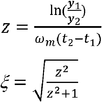
Las distintas operaciones descritas anteriormente con respecto a las distintas figuras se pueden realizar en tiempo real o casi real, a diferencia de las soluciones tradicionales en las que el procesamiento de datos se lleva a cabo después de sufrir demoras asociadas con actividades como la recopilación de datos (esperando reunir suficiente cantidad de datos) y el transporte de datos (por ejemplo, utilizando varios tipos de medios de almacenamiento). The various operations described above with respect to the various figures can be performed in real or near real time, unlike traditional solutions where data processing takes place after experiencing delays associated with activities such as data collection. (hoping to collect enough data) and data transport (for example, using various types of storage media).
Además, en algunas implementaciones a modo de ejemplo, las muestras de datos digitales con las que trabaja el sistema de monitorización de oscilaciones 150 pueden tener una marca de tiempo (con una referencia de tiempo absoluto, por ejemplo). Cuando se marca el tiempo, la estimación de la magnitud de la oscilación y la fase 225 y la estimación de la relación de amortiguamiento de oscilación 230 proporcionan información de sincrofasor de una o más frecuencias de oscilación en una banda de frecuencia predefinida, como la cuarta banda de frecuencia predefinida o la quinta banda de frecuencia predefinida. Esta información del sincrofasor se puede utilizar con fines de comparación entre dos ubicaciones geográficamente separadas que tienen la misma frecuencia de oscilación. Por lo tanto, la información del ángulo de fase del sincrofasor obtenida en una primera ubicación puede compararse con la información del ángulo de fase del sincrofasor obtenida en una segunda ubicación. La información del sincrofasor obtenida de acuerdo con algunas realizaciones de la invención puede tener ciertas tolerancias que pueden ocurrir cuando no se lleva a cabo una compensación de desplazamientos de fase y retardos causados por varios filtros. En tales casos, la información de sincrofasores puede interpretarse como información de cuasi sincrofasores y denominarse SynchroOscPhasor de acuerdo con la invención. Additionally, in some exemplary implementations, the digital data samples that the oscillation monitoring system 150 works with may be timestamped (with a time reference absolute, for example). When timed, the oscillation magnitude and phase estimate 225 and the oscillation damping ratio estimate 230 provide synchrophasor information of one or more oscillation frequencies in a predefined frequency band, such as the fourth preset frequency band or the fifth preset frequency band. This synchrophasor information can be used for comparison purposes between two geographically separate locations that have the same oscillation frequency. Therefore, synchrophasor phase angle information obtained at a first location can be compared with synchrophasor phase angle information obtained at a second location. The synchrophasor information obtained according to some embodiments of the invention may have certain tolerances that may occur when compensation for phase shifts and delays caused by various filters is not performed. In such cases, the synchrophasor information may be interpreted as quasi synchrophasor information and called a SynchroOscPhasor in accordance with the invention.
Claims (1)
Applications Claiming Priority (1)
| Application Number | Priority Date | Filing Date | Title |
|---|---|---|---|
| US15/687,847 US10983150B2 (en) | 2017-08-28 | 2017-08-28 | Systems and methods for detecting and evaluating oscillations in an electrical power grid |
Publications (1)
| Publication Number | Publication Date |
|---|---|
| ES2934005T3 true ES2934005T3 (en) | 2023-02-15 |
Family
ID=63371570
Family Applications (1)
| Application Number | Title | Priority Date | Filing Date |
|---|---|---|---|
| ES18190469T Active ES2934005T3 (en) | 2017-08-28 | 2018-08-23 | Systems and methods to detect and evaluate oscillations in an electrical network |
Country Status (8)
| Country | Link |
|---|---|
| US (1) | US10983150B2 (en) |
| EP (1) | EP3451482B1 (en) |
| JP (1) | JP7184482B2 (en) |
| CN (1) | CN109425784A (en) |
| BR (1) | BR102018067380B1 (en) |
| CA (1) | CA3014464A1 (en) |
| ES (1) | ES2934005T3 (en) |
| MX (1) | MX394686B (en) |
Families Citing this family (4)
| Publication number | Priority date | Publication date | Assignee | Title |
|---|---|---|---|---|
| DE102018120768A1 (en) * | 2018-08-24 | 2020-02-27 | Wobben Properties Gmbh | Wind turbine and method for detecting low-frequency vibrations in an electrical supply network |
| CN110021962B (en) * | 2019-05-06 | 2020-10-27 | 河北新天科创新能源技术有限公司 | Method and device for determining oscillation coupling frequency of new energy grid-connected system |
| EP4170848A1 (en) | 2021-10-20 | 2023-04-26 | Wobben Properties GmbH | Method for damping low-frequency vibrations in an electrical supply network |
| CN114441899B (en) * | 2022-01-27 | 2024-09-06 | 中国电力科学研究院有限公司 | Power grid broadband oscillation monitoring point deployment method, system, device and storage medium |
Family Cites Families (31)
| Publication number | Priority date | Publication date | Assignee | Title |
|---|---|---|---|---|
| JPS51130848A (en) * | 1975-05-08 | 1976-11-13 | Mitsubishi Electric Corp | System protector |
| US4384246A (en) | 1981-01-30 | 1983-05-17 | General Electric Company | Series-thyristor subsynchronous damper for power generators |
| JPH061949B2 (en) * | 1984-01-11 | 1994-01-05 | 財団法人電力中央研究所 | Generator shaft torsion torque suppression method |
| US4788653A (en) | 1986-12-23 | 1988-11-29 | General Electric Company | Digital filter for power system stabilizer |
| US5179489A (en) * | 1990-04-04 | 1993-01-12 | Oliver Bernard M | Method and means for suppressing geomagnetically induced currents |
| US5729145A (en) | 1992-07-30 | 1998-03-17 | Siemens Energy & Automation, Inc. | Method and apparatus for detecting arcing in AC power systems by monitoring high frequency noise |
| SE500683C2 (en) | 1992-09-15 | 1994-08-08 | Asea Brown Boveri | Method and apparatus for detecting and attenuating oscillations at or near a resonant frequency in a power transmission system |
| US5809045A (en) | 1996-09-13 | 1998-09-15 | General Electric Company | Digital current differential system |
| EP0944945A4 (en) | 1996-11-14 | 2000-08-16 | Brian Tolley Corp Limited | Improvements relating to signalling in electricity distribution systems |
| SE517714C2 (en) | 2000-05-31 | 2002-07-09 | Abb Ab | Mains protection system for protecting the integrity of a total electrical power system against slightly damped power fluctuations, electric power system including a network protection, system protection system procedure, system protection terminal, computer program product and computer readable medium |
| SE517963C2 (en) | 2000-05-31 | 2002-08-06 | Abb Ab | Mains protection system for the protection of the integrity of a total electrical power system, electric power system including a network protection, system protection procedure, system protection terminal and computer software product |
| JP2001352679A (en) | 2000-06-09 | 2001-12-21 | Hitachi Ltd | Power system stabilization device and monitoring device |
| US7490013B2 (en) * | 2003-12-09 | 2009-02-10 | Oslsoft, Inc. | Power grid failure detection system and method |
| DE102004011551A1 (en) * | 2004-03-08 | 2005-09-29 | A. Eberle Gmbh | Device for the prevention of major disorders in electrical supply networks |
| JP4906634B2 (en) * | 2007-08-08 | 2012-03-28 | 株式会社日立製作所 | Power system stability diagnostic apparatus and method |
| CN101237148B (en) | 2008-01-23 | 2011-04-20 | 南京南瑞继保电气有限公司 | Low-frequency surge detection and protection method for power system |
| US8000914B2 (en) | 2008-03-04 | 2011-08-16 | Washington State University | Systems and methods for electromechanical oscillation monitoring |
| JP5697956B2 (en) | 2010-11-22 | 2015-04-08 | 一般財団法人電力中央研究所 | Reduced model determination apparatus, reduced model determination method, and reduced model determination program |
| CN102305891B (en) * | 2011-07-04 | 2013-09-11 | 武汉大学 | On-line monitoring method of low-frequency oscillation of power system |
| US20140246914A1 (en) | 2011-09-12 | 2014-09-04 | Alstom Technology Ltd. | Sub-Synchronous Oscillation Damping By Shunt Facts Apparatus |
| US9350163B2 (en) * | 2011-10-19 | 2016-05-24 | General Electric Company | Inter-area oscillation detection |
| US9018962B2 (en) | 2012-04-25 | 2015-04-28 | Advanced Power Technologies, Inc | Method and apparatus for protecting power transformers from large electro-magnetic disturbances |
| US10756543B2 (en) * | 2012-09-13 | 2020-08-25 | Stem, Inc. | Method and apparatus for stabalizing power on an electrical grid using networked distributed energy storage systems |
| US9385533B2 (en) | 2013-05-30 | 2016-07-05 | General Electric Company | Power system stabilization |
| US10025336B2 (en) * | 2013-10-16 | 2018-07-17 | General Electric Company | System and method for analyzing oscillatory stability in electrical power transmission systems |
| JP6348862B2 (en) * | 2015-03-30 | 2018-06-27 | 株式会社日立製作所 | System stabilization control device and power system control system |
| CN105301405B (en) * | 2015-11-16 | 2018-01-16 | 清华大学 | A kind of method and device for being used to determine the sub-synchronous oscillation disturbing source of power system |
| CN105606895B (en) * | 2016-01-07 | 2019-04-23 | 国家电网公司 | On-line Detection and Filtering Method of Subsynchronous Oscillation Component in Power System |
| GB201601472D0 (en) | 2016-01-26 | 2016-03-09 | Alstom Grid Uk Ltd | Oscillations in electrical power networks |
| US10622813B2 (en) * | 2016-08-04 | 2020-04-14 | Rolls-Royce North American Technologies Inc. | Load alignment assistance during startup of synchronous grid |
| US9806690B1 (en) * | 2016-09-30 | 2017-10-31 | AEP Transmission Holding Company, LLC | Subsynchronous oscillation relay |
-
2017
- 2017-08-28 US US15/687,847 patent/US10983150B2/en active Active
-
2018
- 2018-08-16 CA CA3014464A patent/CA3014464A1/en active Pending
- 2018-08-22 JP JP2018155155A patent/JP7184482B2/en active Active
- 2018-08-23 EP EP18190469.9A patent/EP3451482B1/en active Active
- 2018-08-23 ES ES18190469T patent/ES2934005T3/en active Active
- 2018-08-27 MX MX2018010320A patent/MX394686B/en unknown
- 2018-08-28 CN CN201810986724.6A patent/CN109425784A/en active Pending
- 2018-08-31 BR BR102018067380-7A patent/BR102018067380B1/en not_active IP Right Cessation
Also Published As
| Publication number | Publication date |
|---|---|
| US10983150B2 (en) | 2021-04-20 |
| JP2019062730A (en) | 2019-04-18 |
| JP7184482B2 (en) | 2022-12-06 |
| EP3451482B1 (en) | 2022-10-19 |
| BR102018067380B1 (en) | 2023-10-17 |
| CN109425784A (en) | 2019-03-05 |
| EP3451482A1 (en) | 2019-03-06 |
| BR102018067380A2 (en) | 2019-03-19 |
| US20190064232A1 (en) | 2019-02-28 |
| CA3014464A1 (en) | 2019-02-28 |
| MX394686B (en) | 2025-03-24 |
Similar Documents
| Publication | Publication Date | Title |
|---|---|---|
| ES2934005T3 (en) | Systems and methods to detect and evaluate oscillations in an electrical network | |
| ES2959091T3 (en) | Apparatus and method for fault detection and location determination | |
| ES2333381T3 (en) | DETECTION OF FAILURES IN ENERGY SYSTEMS. | |
| KR101303597B1 (en) | A detection device of insulation resistance for non-interruption of electric power and hot-line | |
| CA2946180C (en) | Relay protection method and apparatus against lc parallel circuit detuning faults | |
| JP7637363B2 (en) | Method and device for monitoring insulation between a DC bus and protective earth - Patents.com | |
| JP6189430B2 (en) | Device for measuring ground resistance and in-vehicle charger having such a device | |
| JP6127824B2 (en) | Power conditioner system for photovoltaic power generation | |
| WO2016188568A1 (en) | Travelling wave protection of a transmission line based on high-pass filtering | |
| CN102262199A (en) | Identification and directional detection of defect in a three-phase network | |
| US9606169B2 (en) | Protection apparatus and method of verifying operation thereof | |
| CN103616615A (en) | Single-phase earth fault locating method of power distribution network | |
| KR100920153B1 (en) | Device for measuring leakage current effective component in cable line and its method | |
| RU2682240C2 (en) | Detecting fault, in particular transient fault in electrical network | |
| ES2959976T3 (en) | Method for detecting ground fault conditions in a power conversion apparatus | |
| CN103487724A (en) | Single-phase ground fault positioning method of power distribution network | |
| KR101075484B1 (en) | Measurement Device of leakage current ohmic value on power line And Method Thereof | |
| US11101631B2 (en) | Downed conductor detection | |
| CN103454561B (en) | A kind of one-phase earthing failure in electric distribution network localization method | |
| JP6149546B2 (en) | Malfunction prevention device and malfunction prevention method for ground fault protection relay | |
| Shekhar et al. | DC microgrid protection by selective detection of series arcing using load side power electronic devices | |
| Saijai et al. | Earth leakage current detection and identification scheme for a single-phase low-voltage electrical appliance system using frequency domain analysis | |
| JP2014013155A (en) | Frequency detection device and frequency relay using the same | |
| Bejmert | Loss-of-mains detection by frequency protection functions | |
| Silva et al. | Decaying dc component effect elimination on phasor estimation using an adaptive filtering algorithm |