ES2945219T3 - Shock wave generating device and shock wave ablation system - Google Patents
Shock wave generating device and shock wave ablation system Download PDFInfo
- Publication number
- ES2945219T3 ES2945219T3 ES19776260T ES19776260T ES2945219T3 ES 2945219 T3 ES2945219 T3 ES 2945219T3 ES 19776260 T ES19776260 T ES 19776260T ES 19776260 T ES19776260 T ES 19776260T ES 2945219 T3 ES2945219 T3 ES 2945219T3
- Authority
- ES
- Spain
- Prior art keywords
- shock wave
- laser beam
- optical fiber
- concave surface
- equation
- Prior art date
- Legal status (The legal status is an assumption and is not a legal conclusion. Google has not performed a legal analysis and makes no representation as to the accuracy of the status listed.)
- Active
Links
- 230000035939 shock Effects 0.000 title claims abstract description 225
- 238000002679 ablation Methods 0.000 title claims abstract description 8
- 239000013307 optical fiber Substances 0.000 claims abstract description 112
- 239000007788 liquid Substances 0.000 claims abstract description 40
- 238000007789 sealing Methods 0.000 claims abstract description 20
- 238000005520 cutting process Methods 0.000 claims description 21
- XLYOFNOQVPJJNP-UHFFFAOYSA-N water Substances O XLYOFNOQVPJJNP-UHFFFAOYSA-N 0.000 description 21
- 230000014509 gene expression Effects 0.000 description 16
- WZFUQSJFWNHZHM-UHFFFAOYSA-N 2-[4-[2-(2,3-dihydro-1H-inden-2-ylamino)pyrimidin-5-yl]piperazin-1-yl]-1-(2,4,6,7-tetrahydrotriazolo[4,5-c]pyridin-5-yl)ethanone Chemical compound C1C(CC2=CC=CC=C12)NC1=NC=C(C=N1)N1CCN(CC1)CC(=O)N1CC2=C(CC1)NN=N2 WZFUQSJFWNHZHM-UHFFFAOYSA-N 0.000 description 12
- 239000000463 material Substances 0.000 description 8
- 238000005498 polishing Methods 0.000 description 8
- 239000010453 quartz Substances 0.000 description 8
- VYPSYNLAJGMNEJ-UHFFFAOYSA-N silicon dioxide Inorganic materials O=[Si]=O VYPSYNLAJGMNEJ-UHFFFAOYSA-N 0.000 description 8
- 230000000052 comparative effect Effects 0.000 description 7
- 230000000694 effects Effects 0.000 description 7
- 239000000835 fiber Substances 0.000 description 7
- 238000012986 modification Methods 0.000 description 7
- 230000004048 modification Effects 0.000 description 7
- 238000005259 measurement Methods 0.000 description 6
- OHVLMTFVQDZYHP-UHFFFAOYSA-N 1-(2,4,6,7-tetrahydrotriazolo[4,5-c]pyridin-5-yl)-2-[4-[2-[[3-(trifluoromethoxy)phenyl]methylamino]pyrimidin-5-yl]piperazin-1-yl]ethanone Chemical compound N1N=NC=2CN(CCC=21)C(CN1CCN(CC1)C=1C=NC(=NC=1)NCC1=CC(=CC=C1)OC(F)(F)F)=O OHVLMTFVQDZYHP-UHFFFAOYSA-N 0.000 description 5
- 238000000576 coating method Methods 0.000 description 5
- 239000002245 particle Substances 0.000 description 5
- 206010003119 arrhythmia Diseases 0.000 description 4
- 239000011248 coating agent Substances 0.000 description 4
- 238000000034 method Methods 0.000 description 4
- 210000001519 tissue Anatomy 0.000 description 4
- 239000003082 abrasive agent Substances 0.000 description 3
- 230000006793 arrhythmia Effects 0.000 description 3
- 230000005484 gravity Effects 0.000 description 3
- 230000001678 irradiating effect Effects 0.000 description 3
- 239000002184 metal Substances 0.000 description 3
- 229910052751 metal Inorganic materials 0.000 description 3
- 210000004165 myocardium Anatomy 0.000 description 3
- -1 polyethylene Polymers 0.000 description 3
- 239000011347 resin Substances 0.000 description 3
- 229920005989 resin Polymers 0.000 description 3
- 229920003002 synthetic resin Polymers 0.000 description 3
- 239000000057 synthetic resin Substances 0.000 description 3
- 239000010409 thin film Substances 0.000 description 3
- 229910021642 ultra pure water Inorganic materials 0.000 description 3
- 239000012498 ultrapure water Substances 0.000 description 3
- DEXFNLNNUZKHNO-UHFFFAOYSA-N 6-[3-[4-[2-(2,3-dihydro-1H-inden-2-ylamino)pyrimidin-5-yl]piperidin-1-yl]-3-oxopropyl]-3H-1,3-benzoxazol-2-one Chemical compound C1C(CC2=CC=CC=C12)NC1=NC=C(C=N1)C1CCN(CC1)C(CCC1=CC2=C(NC(O2)=O)C=C1)=O DEXFNLNNUZKHNO-UHFFFAOYSA-N 0.000 description 2
- 229910001369 Brass Inorganic materials 0.000 description 2
- 238000011298 ablation treatment Methods 0.000 description 2
- 238000002835 absorbance Methods 0.000 description 2
- 238000000137 annealing Methods 0.000 description 2
- 230000015572 biosynthetic process Effects 0.000 description 2
- 239000010951 brass Substances 0.000 description 2
- 238000004364 calculation method Methods 0.000 description 2
- 230000003247 decreasing effect Effects 0.000 description 2
- 238000010586 diagram Methods 0.000 description 2
- 239000010408 film Substances 0.000 description 2
- 239000011521 glass Substances 0.000 description 2
- 230000001338 necrotic effect Effects 0.000 description 2
- 230000010355 oscillation Effects 0.000 description 2
- 229920002379 silicone rubber Polymers 0.000 description 2
- 239000004945 silicone rubber Substances 0.000 description 2
- YLZOPXRUQYQQID-UHFFFAOYSA-N 3-(2,4,6,7-tetrahydrotriazolo[4,5-c]pyridin-5-yl)-1-[4-[2-[[3-(trifluoromethoxy)phenyl]methylamino]pyrimidin-5-yl]piperazin-1-yl]propan-1-one Chemical compound N1N=NC=2CN(CCC=21)CCC(=O)N1CCN(CC1)C=1C=NC(=NC=1)NCC1=CC(=CC=C1)OC(F)(F)F YLZOPXRUQYQQID-UHFFFAOYSA-N 0.000 description 1
- 239000004925 Acrylic resin Substances 0.000 description 1
- 229920000178 Acrylic resin Polymers 0.000 description 1
- 239000004698 Polyethylene Substances 0.000 description 1
- 239000004743 Polypropylene Substances 0.000 description 1
- FAPWRFPIFSIZLT-UHFFFAOYSA-M Sodium chloride Chemical compound [Na+].[Cl-] FAPWRFPIFSIZLT-UHFFFAOYSA-M 0.000 description 1
- 241000973887 Takayama Species 0.000 description 1
- 238000010521 absorption reaction Methods 0.000 description 1
- CCDWGDHTPAJHOA-UHFFFAOYSA-N benzylsilicon Chemical compound [Si]CC1=CC=CC=C1 CCDWGDHTPAJHOA-UHFFFAOYSA-N 0.000 description 1
- 238000005253 cladding Methods 0.000 description 1
- 238000013461 design Methods 0.000 description 1
- 238000005516 engineering process Methods 0.000 description 1
- 238000002474 experimental method Methods 0.000 description 1
- 210000003734 kidney Anatomy 0.000 description 1
- 238000004519 manufacturing process Methods 0.000 description 1
- 150000002739 metals Chemical class 0.000 description 1
- NRNCYVBFPDDJNE-UHFFFAOYSA-N pemoline Chemical compound O1C(N)=NC(=O)C1C1=CC=CC=C1 NRNCYVBFPDDJNE-UHFFFAOYSA-N 0.000 description 1
- 229920001921 poly-methyl-phenyl-siloxane Polymers 0.000 description 1
- 229920000573 polyethylene Polymers 0.000 description 1
- 229920000139 polyethylene terephthalate Polymers 0.000 description 1
- 239000005020 polyethylene terephthalate Substances 0.000 description 1
- 229920001155 polypropylene Polymers 0.000 description 1
- 239000000523 sample Substances 0.000 description 1
- 238000004088 simulation Methods 0.000 description 1
- 239000011780 sodium chloride Substances 0.000 description 1
- 229910001220 stainless steel Inorganic materials 0.000 description 1
- 239000010935 stainless steel Substances 0.000 description 1
- 239000004575 stone Substances 0.000 description 1
- 238000011282 treatment Methods 0.000 description 1
- 210000000626 ureter Anatomy 0.000 description 1
Classifications
-
- A—HUMAN NECESSITIES
- A61—MEDICAL OR VETERINARY SCIENCE; HYGIENE
- A61B—DIAGNOSIS; SURGERY; IDENTIFICATION
- A61B18/00—Surgical instruments, devices or methods for transferring non-mechanical forms of energy to or from the body
- A61B18/18—Surgical instruments, devices or methods for transferring non-mechanical forms of energy to or from the body by applying electromagnetic radiation, e.g. microwaves
- A61B18/20—Surgical instruments, devices or methods for transferring non-mechanical forms of energy to or from the body by applying electromagnetic radiation, e.g. microwaves using laser
- A61B18/22—Surgical instruments, devices or methods for transferring non-mechanical forms of energy to or from the body by applying electromagnetic radiation, e.g. microwaves using laser the beam being directed along or through a flexible conduit, e.g. an optical fibre; Couplings or hand-pieces therefor
- A61B18/26—Surgical instruments, devices or methods for transferring non-mechanical forms of energy to or from the body by applying electromagnetic radiation, e.g. microwaves using laser the beam being directed along or through a flexible conduit, e.g. an optical fibre; Couplings or hand-pieces therefor for producing a shock wave, e.g. laser lithotripsy
-
- G—PHYSICS
- G02—OPTICS
- G02B—OPTICAL ELEMENTS, SYSTEMS OR APPARATUS
- G02B6/00—Light guides; Structural details of arrangements comprising light guides and other optical elements, e.g. couplings
- G02B6/24—Coupling light guides
- G02B6/26—Optical coupling means
- G02B6/262—Optical details of coupling light into, or out of, or between fibre ends, e.g. special fibre end shapes or associated optical elements
-
- A—HUMAN NECESSITIES
- A61—MEDICAL OR VETERINARY SCIENCE; HYGIENE
- A61B—DIAGNOSIS; SURGERY; IDENTIFICATION
- A61B18/00—Surgical instruments, devices or methods for transferring non-mechanical forms of energy to or from the body
- A61B2018/00571—Surgical instruments, devices or methods for transferring non-mechanical forms of energy to or from the body for achieving a particular surgical effect
- A61B2018/00577—Ablation
-
- A—HUMAN NECESSITIES
- A61—MEDICAL OR VETERINARY SCIENCE; HYGIENE
- A61B—DIAGNOSIS; SURGERY; IDENTIFICATION
- A61B18/00—Surgical instruments, devices or methods for transferring non-mechanical forms of energy to or from the body
- A61B18/18—Surgical instruments, devices or methods for transferring non-mechanical forms of energy to or from the body by applying electromagnetic radiation, e.g. microwaves
- A61B18/20—Surgical instruments, devices or methods for transferring non-mechanical forms of energy to or from the body by applying electromagnetic radiation, e.g. microwaves using laser
- A61B18/22—Surgical instruments, devices or methods for transferring non-mechanical forms of energy to or from the body by applying electromagnetic radiation, e.g. microwaves using laser the beam being directed along or through a flexible conduit, e.g. an optical fibre; Couplings or hand-pieces therefor
- A61B2018/2255—Optical elements at the distal end of probe tips
- A61B2018/2266—Optical elements at the distal end of probe tips with a lens, e.g. ball tipped
-
- A—HUMAN NECESSITIES
- A61—MEDICAL OR VETERINARY SCIENCE; HYGIENE
- A61B—DIAGNOSIS; SURGERY; IDENTIFICATION
- A61B18/00—Surgical instruments, devices or methods for transferring non-mechanical forms of energy to or from the body
- A61B18/18—Surgical instruments, devices or methods for transferring non-mechanical forms of energy to or from the body by applying electromagnetic radiation, e.g. microwaves
- A61B18/20—Surgical instruments, devices or methods for transferring non-mechanical forms of energy to or from the body by applying electromagnetic radiation, e.g. microwaves using laser
- A61B18/22—Surgical instruments, devices or methods for transferring non-mechanical forms of energy to or from the body by applying electromagnetic radiation, e.g. microwaves using laser the beam being directed along or through a flexible conduit, e.g. an optical fibre; Couplings or hand-pieces therefor
- A61B2018/2255—Optical elements at the distal end of probe tips
- A61B2018/2272—Optical elements at the distal end of probe tips with reflective or refractive surfaces for deflecting the beam
-
- A—HUMAN NECESSITIES
- A61—MEDICAL OR VETERINARY SCIENCE; HYGIENE
- A61B—DIAGNOSIS; SURGERY; IDENTIFICATION
- A61B18/00—Surgical instruments, devices or methods for transferring non-mechanical forms of energy to or from the body
- A61B18/18—Surgical instruments, devices or methods for transferring non-mechanical forms of energy to or from the body by applying electromagnetic radiation, e.g. microwaves
- A61B18/20—Surgical instruments, devices or methods for transferring non-mechanical forms of energy to or from the body by applying electromagnetic radiation, e.g. microwaves using laser
- A61B18/22—Surgical instruments, devices or methods for transferring non-mechanical forms of energy to or from the body by applying electromagnetic radiation, e.g. microwaves using laser the beam being directed along or through a flexible conduit, e.g. an optical fibre; Couplings or hand-pieces therefor
- A61B18/26—Surgical instruments, devices or methods for transferring non-mechanical forms of energy to or from the body by applying electromagnetic radiation, e.g. microwaves using laser the beam being directed along or through a flexible conduit, e.g. an optical fibre; Couplings or hand-pieces therefor for producing a shock wave, e.g. laser lithotripsy
- A61B2018/263—Surgical instruments, devices or methods for transferring non-mechanical forms of energy to or from the body by applying electromagnetic radiation, e.g. microwaves using laser the beam being directed along or through a flexible conduit, e.g. an optical fibre; Couplings or hand-pieces therefor for producing a shock wave, e.g. laser lithotripsy the conversion of laser energy into mechanical shockwaves taking place in a liquid
Landscapes
- Physics & Mathematics (AREA)
- Health & Medical Sciences (AREA)
- Optics & Photonics (AREA)
- Surgery (AREA)
- Life Sciences & Earth Sciences (AREA)
- Heart & Thoracic Surgery (AREA)
- General Health & Medical Sciences (AREA)
- Nuclear Medicine, Radiotherapy & Molecular Imaging (AREA)
- Engineering & Computer Science (AREA)
- Biomedical Technology (AREA)
- Electromagnetism (AREA)
- Medical Informatics (AREA)
- Molecular Biology (AREA)
- Animal Behavior & Ethology (AREA)
- Otolaryngology (AREA)
- Public Health (AREA)
- Veterinary Medicine (AREA)
- General Physics & Mathematics (AREA)
- Laser Surgery Devices (AREA)
- Surgical Instruments (AREA)
- Pinball Game Machines (AREA)
- Paper (AREA)
Abstract
[Problema] Proporcionar un dispositivo generador de ondas de choque y un sistema de ablación de ondas de choque con el que las ondas de choque generadas en un líquido puedan reflejarse de forma eficiente y hacer que converjan. [Solución] Se proporciona un dispositivo generador de ondas de choque (10) con una fibra óptica (11) y una parte reflectante (12), y hace que las ondas de choque generadas dentro de la parte reflectante se reflejen y converjan fuera de la parte reflectante. La parte reflectante (12) comprende: un cuerpo reflectante (20) provisto de una superficie cóncava (21) que tiene una forma de superficie rotacional recortada, y un orificio pasante (22) que está dispuesto coaxialmente con el eje de rotación de la superficie cóncava (21) ya través del cual se inserta la fibra óptica (11); un cuerpo de sellado (23) que sella una porción de abertura de la superficie cóncava (21); y un líquido (24) que llena un espacio entre la superficie cóncava (12) y el cuerpo de sellado (23). Un extremo distal de la fibra óptica (11) está dispuesto en una posición más alejada del lado posterior que un punto focal (F) de la superficie cóncava (21), y que permite que las ondas de choque sean reflejadas por la superficie cóncava (21) para converger fuera de la parte reflectante (12). (Traducción automática con Google Translate, sin valor legal)[Problem] To provide a shock wave generating device and a shock wave ablation system with which shock waves generated in a liquid can be efficiently reflected and caused to converge. [Solution] A shock wave generating device (10) is provided with an optical fiber (11) and a reflecting part (12), and causes shock waves generated within the reflecting part to be reflected and converged outside the reflecting part. The reflecting part (12) comprises: a reflecting body (20) provided with a concave surface (21) having a cut-out rotational surface shape, and a through hole (22) which is coaxially arranged with the rotation axis of the concave surface (21) and through which the optical fiber (11) is inserted; a sealing body (23) which seals an opening portion of the concave surface (21); and a liquid (24) filling a space between the concave surface (12) and the sealing body (23). A distal end of the optical fiber (11) is arranged at a position farther from the rear side than a focal point (F) of the concave surface (21), and which allows shock waves reflected by the concave surface (21) to converge outside the reflecting portion (12). (Automatic translation with Google Translate, without legal value)
Description
DESCRIPCIÓNDESCRIPTION
Dispositivo generador de ondas de choque y sistema de ablación por ondas de choqueShock wave generating device and shock wave ablation system
Campo técnicotechnical field
La presente invención se refiere a un dispositivo generador de ondas de choque y a un sistema de ablación por ondas de choque.The present invention relates to a shock wave generating device and a shock wave ablation system.
Técnica anteriorprior art
Se conoce un dispositivo generador de ondas de choque configurado para irradiar un rayo láser de pulso bajo el agua, y reflejar y converger la onda de choque generada bajo el agua para aplastar y eliminar un cálculo en un uréter o riñón.A shock wave generating device configured to irradiate a pulsed laser beam underwater, and reflect and converge the shock wave generated underwater to crush and remove a stone in a ureter or kidney is known.
Los inventores de la presente invención han logrado desarrollar, como se describe en la literatura de patentes 1, un dispositivo generador de ondas de choque que incluye una fibra óptica y un reflector cilíndrico, estando el dispositivo generador de ondas de choque reducido a un tamaño que puede incorporarse a un catéter. Con el dispositivo generador de ondas de choque, los inventores han propuesto un método para tratar la arritmia, en el que un tejido muscular cardíaco causante de la arritmia, en particular, un tejido muscular cardíaco en una parte profunda se necrosa desde un lado endocárdico a través del catéter. Los inventores de la presente invención también han propuesto, como se describe en la literatura de patentes 2, una fibra óptica apta para tal dispositivo generador de ondas de choque.The inventors of the present invention have succeeded in developing, as described in the patent literature 1, a shock wave generating device including an optical fiber and a cylindrical reflector, the shock wave generating device being reduced to a size that It can be incorporated into a catheter. With the shock wave generating device, the inventors have proposed a method for treating arrhythmia, in which an arrhythmia-causing cardiac muscle tissue, in particular, a cardiac muscle tissue in a deep part, is necrotic from an endocardial side to through the catheter. The inventors of the present invention have also proposed, as described in the patent literature 2, an optical fiber suitable for such a shock wave generating device.
Además, los inventores de la presente invención han informado, como se describe en la literatura no patentada 1, que, cuando la forma de un extremo distal de una fibra óptica se forma en un cono truncado, la forma de un frente de onda es diferente dependiendo del ángulo de conicidad a, y el frente de onda de la onda de choque se acerca más a la forma esférica a medida que el ángulo de conicidad a se vuelve más grande. Los inventores también han informado que, cuando el ángulo de conicidad a es de 20° a 50°, el frente de onda de la onda de choque se hincha desde una dirección de emisión láser hacia atrás a medida que el ángulo de conicidad a se vuelve más pequeño, y cuando el ángulo de conicidad a es de 30° a 50°, se maximizó una intensidad (sobrepresión) de la onda de choque. Lista de citasFurthermore, the inventors of the present invention have reported, as described in non-patent literature 1, that when the shape of a distal end of an optical fiber is formed into a truncated cone, the shape of a wavefront is different depending on the taper angle a, and the wavefront of the shock wave becomes closer to spherical shape as the taper angle a becomes larger. The inventors have also reported that, when the taper angle a is 20° to 50°, the shock wave wavefront swells from a backward lasing direction as the taper angle a becomes smaller, and when the taper angle a is 30° to 50°, an intensity (overpressure) of the shock wave was maximized. appointment list
Literatura de patentespatent literature
PTL 1: JP 4635233 B2PTL 1: JP 4635233 B2
PTL 2: JP 5435739 B2PTL 2: JP 5435739 B2
Literatura no patentadaNon-proprietary literature
NPL 1: YAMAMOTO Hiroaki, TAKAYAMA Kazuyoshi y SHIMOKAWA Hiroaki, "Behavior change of under- water shock wave generated by Q-switched Ho:YAG laser beam due to the shape of the fiber tip [Cambio de comportamiento de la onda de choque ajo el agua generada por un rayo láser Ho:YAG de conmutación Q debido a la forma de la punta de la fibra]", Procesos del simposio sobre ondas de choque en JAPÓN 2013, 1B2-6NPL 1: YAMAMOTO Hiroaki, TAKAYAMA Kazuyoshi, and SHIMOKAWA Hiroaki, "Behavior change of under- water shock wave generated by Q-switched Ho:YAG laser beam due to the shape of the fiber tip water generated by a Q-switched Ho:YAG laser beam due to the shape of the fiber tip]", Proceedings of the Symposium on Shock Waves in JAPAN 2013, 1B2-6
US-A-2013/274726 y EP-A-0 192833 divulgan un dispositivo generador de ondas de choque. El formulario de dos partes se basa en el primero.US-A-2013/274726 and EP-A-0 192833 disclose a shock wave generating device. The two-part form builds on the first.
Resumen de la invenciónSummary of the invention
Problema técnicotechnical problem
Mientras tanto, en un dispositivo generador de ondas de choque de tecnología afín, el extremo distal de una fibra óptica suele estar dispuesto de forma que coincida con el punto focal de una superficie cóncava de un reflector, y no se ha tenido en cuenta la distorsión del frente de onda de la onda de choque mencionada anteriormente. Como resultado de realizar repetidamente experimentos detallados sobre esos puntos, los inventores de la presente invención han descubierto que, mediante la disposición del extremo distal de la fibra óptica en una posición adecuada detrás del punto focal de la superficie cóncava, la onda de choque puede reflejarse y converger eficazmente en un punto (punto convergente) fuera de una parte reflectante, y la sobrepresión de la onda de choque puede aumentarse drásticamente.Meanwhile, in a related technology shock wave generating device, the distal end of an optical fiber is usually arranged to coincide with the focal point of a concave surface of a reflector, and distortion has not been taken into account. from the wave front of the aforementioned shock wave. As a result of repeatedly performing detailed experiments on those points, the inventors of the present invention have found that by arranging the distal end of the optical fiber at a suitable position behind the focal point of the concave surface, the shock wave can be reflected and effectively converge to a point (converging point) outside a reflective part, and the overpressure of the shock wave can be drastically increased.
En otras palabras, la presente invención tiene el objeto de proporcionar un dispositivo generador de ondas de choque y un sistema de ablación por ondas de choque, con los cuales la onda de choque generada en un líquido puede reflejarse y converger eficazmente. In other words, the present invention has an object to provide a shock wave generating device and a shock wave ablation system, with which the shock wave generated in a liquid can be effectively reflected and converged.
Solución al problemaSolution to the problem
Según una realización de la presente invención, se proporciona un dispositivo generador de ondas de choque que incluye: una fibra óptica; y una parte reflectante, estando configurado el dispositivo generador de ondas de choque para reflejar y converger la onda de choque generada dentro de la parte reflectante hacia el exterior de la parte reflectante, la parte reflectante incluye: un reflector que tiene una superficie cóncava, que se proporciona en un lado extremo, y tiene una forma de superficie de revolución cortada obtenida cortando un esferoide en el que un eje principal es un eje de rotación, o una superficie curva obtenida modificando el esferoide, y un orificio pasante, que se forma coaxialmente con el eje de rotación, y en el que se va a insertar la fibra óptica desde el otro lado extremo; un cuerpo de sellado configurado para sellar una parte de abertura de la superficie cóncava; y un líquido que se va a cargar entre la superficie cóncava y el cuerpo de sellado, teniendo la fibra óptica un extremo distal dispuesto en una posición en el otro extremo de un punto focal de la superficie cóncava en la parte reflectante, en la que la onda de choque reflejada por la superficie cóncava es convergente fuera de la parte reflectante.According to one embodiment of the present invention, there is provided a shock wave generating device including: an optical fiber; and a reflective part, the shock wave generating device being configured to reflect and converge the shock wave generated within the reflective part toward the outside of the reflective part, the reflective part includes: a reflector having a concave surface, which it is provided at one end side, and has a shape of a cut surface of revolution obtained by cutting a spheroid in which a principal axis is an axis of rotation, or a curved surface obtained by modifying the spheroid, and a through hole, which is formed coaxially with the axis of rotation, and into which the optical fiber is to be inserted from the other extreme side; a sealing body configured to seal an opening portion of the concave surface; and a liquid to be charged between the concave surface and the sealing body, the optical fiber having a distal end disposed at a position at the other end of a focal point of the concave surface in the reflective part, in which the shock wave reflected by the concave surface is convergent off the reflecting part.
En la presente invención, la "superficie cóncava obtenida al cortar el esferoide en el que el eje principal es el eje de rotación, o la superficie curva obtenida al modificar el esferoide" se refiere a una superficie cóncava obtenida al cortar el esferoide, o la superficie curva obtenida modificando el esferoide, por un plano distinto a un plano paralelo al eje de rotación.In the present invention, the "concave surface obtained by cutting the spheroid in which the main axis is the axis of rotation, or the curved surface obtained by modifying the spheroid" refers to a concave surface obtained by cutting the spheroid, or the curved surface obtained by modifying the spheroid, by a plane other than a plane parallel to the axis of rotation.
Según el dispositivo generador de ondas de choque de la presente invención, el extremo distal de la fibra óptica está dispuesto en una posición en el otro lado extremo del punto focal de la superficie cóncava en la parte reflectante, en el que la onda de choque reflejada por el la superficie cóncava es convergente fuera de la parte reflectante. Por lo tanto, cuando se irradia un rayo láser de pulso desde el extremo distal de la fibra óptica para generar la onda de choque en el líquido, el centro de generación de la onda de choque y el punto focal de la superficie cóncava pueden coincidir sustancialmente entre sí, y como resultado, la onda de choque reflejada por la superficie cóncava puede converger eficazmente hacia un punto fuera de la parte reflectante.According to the shock wave generating device of the present invention, the distal end of the optical fiber is arranged at a position on the other end side of the focal point of the concave surface on the reflective part, in which the reflected shock wave by the concave surface is convergent away from the reflecting part. Therefore, when a pulsed laser beam is irradiated from the distal end of the optical fiber to generate the shock wave in the liquid, the center of generation of the shock wave and the focal point of the concave surface can substantially coincide. each other, and as a result, the shock wave reflected by the concave surface can effectively converge to a point outside the reflecting part.
En el dispositivo generador de ondas de choque según una realización de la presente invención, se prefiere que la fibra óptica incluya, en una parte del extremo distal de la misma, una parte de convergencia del rayo láser que tiene forma de cono truncado. En este caso, el rayo láser de pulso se puede enfocar frente a la parte de convergencia del rayo láser y se puede generar una gran onda de choque en el líquido.In the shock wave generating device according to an embodiment of the present invention, it is preferred that the optical fiber includes, at a distal end portion thereof, a laser beam converging portion having a truncated cone shape. In this case, the pulsed laser beam can be focused in front of the converging part of the laser beam, and a large shock wave can be generated in the liquid.
En el dispositivo generador de ondas de choque según una realización de la presente invención, se prefiere que la distancia Lx desde un extremo distal de la parte de convergencia del rayo láser hasta el punto focal satisfaga la [Ecuación 1] y [Ecuación 2]:In the shock wave generating device according to an embodiment of the present invention, it is preferred that the distance Lx from a distal end of the converging portion of the laser beam to the focal point satisfies [Equation 1] and [Equation 2]:

siempre que, en la [Ecuación 2], "a" represente un ángulo formado por un trapezoide isósceles expresado por una sección transversal en una dirección axial de la parte de convergencia del rayo láser, "nqtz" represente un índice de refracción de un núcleo de la fibra óptica, "nuq" represente un índice de refracción del líquido, "NA" represente una apertura numérica de la fibra óptica, "M" represente un diámetro de núcleo en una parte del extremo proximal de la parte de convergencia del rayo láser y "h" represente una altura de un cono truncado de la parte de convergencia del rayo láser.provided that, in [Equation 2], "a" represents an angle formed by an isosceles trapezoid expressed by a cross section in an axial direction of the converging part of the laser beam, "nqtz" represents a refractive index of one nucleus of the optical fiber, "nuq" represents a refractive index of the liquid, "NA" represents a numerical aperture of the optical fiber, "M" represents a core diameter at a proximal end part of the converging part of the laser beam, and "h" represents a height of a truncated cone of the converging part of the laser beam.
La Condición (I) en la "Ecuación 2" es una condición en la que sustancialmente todo el rayo láser de pulso se refleja totalmente, y la condición (II) es una condición en la que una parte del rayo láser de pulso se refleja totalmente, y la otra parte del mismo es transmitida.Condition (I) in "Equation 2" is a condition in which substantially all of the pulsed laser beam is totally reflected, and condition (II) is a condition in which a part of the pulsed laser beam is totally reflected. , and the other part of it is transmitted.
Además, "d" en cada una de las Condiciones (I) y (II) de la "Ecuación 2" representa, cuando el rayo láser de pulso reflejado totalmente en la parte de convergencia del rayo láser se irradia desde el extremo distal de la parte de convergencia del rayo láser y se enfoca frente a la parte de convergencia del rayo láser, un valor teórico de una distancia entre un punto de enfoque del rayo láser de pulso y el extremo distal de la parte de convergencia del rayo láser.In addition, "d" in each of Conditions (I) and (II) of "Equation 2" represents, when the fully reflected pulse laser beam in the converging part of the laser beam is irradiated from the distal end of the convergence part of the laser beam and is focused opposite the convergence part of the laser beam, a theoretical value of a distance between a focus point of the pulsed laser beam and the distal end of the convergence part of the laser beam.
En el dispositivo generador de ondas de choque según una realización de la presente invención, se prefiere que la distancia Lx desde un extremo distal de la parte de convergencia del rayo láser hasta el punto focal satisfaga la [Ecuación 3] y [Ecuación 4]:In the shock wave generating device according to an embodiment of the present invention, it is preferred that the distance Lx from a distal end of the converging portion of the laser beam to the focal point satisfies [Equation 3] and [Equation 4]:

siempre que, en la [Ecuación 4], "a" represente un ángulo formado por un trapezoide isósceles expresado por una sección transversal en una dirección axial de la parte de convergencia del rayo láser, "nqtz" represente un índice de refracción de un núcleo de la fibra óptica, "nliq" represente un índice de refracción del líquido, "NA" represente una apertura numérica de la fibra óptica, "M" represente un diámetro de núcleo en una parte del extremo proximal de la parte de convergencia del rayo láser y "h" represente una altura de un cono truncado de la parte de convergencia del rayo láser.provided that, in [Equation 4], "a" represents an angle formed by an isosceles trapezoid expressed by a cross section in an axial direction of the converging part of the laser beam, "nqtz" represents a refractive index of one nucleus of the optical fiber, "nliq" represents a refractive index of the liquid, "NA" represents a numerical aperture of the optical fiber, "M" represents a core diameter at a proximal end part of the converging part of the laser beam and "h" represents a height of a frustum of the converging part of the laser beam.
La Condición (III) en la "Ecuación 4" es una condición en la que una parte del rayo láser de pulso distinta de una parte particular del mismo se transmite a través de la parte de convergencia del rayo láser.Condition (III) in "Equation 4" is a condition in which a part of the pulsed laser beam other than a particular part thereof is transmitted through the converging part of the laser beam.
Además, en la "Ecuación 4", "d" representa, cuando la parte del rayo láser de pulso que se ha transmitido a través de la parte de convergencia del rayo láser se enfoca frente a la parte de convergencia del rayo láser, un valor teórico de una distancia entre un punto de enfoque del rayo láser de pulso y el extremo distal de la parte de convergencia del rayo láser.In addition, in "Equation 4", "d" represents, when the part of the pulsed laser beam that has been transmitted through the converging part of the laser beam is focused in front of the converging part of the laser beam, a value theoretical distance between a focus point of the pulsed laser beam and the distal end of the converging part of the laser beam.
En el dispositivo generador de ondas de choque según una realización de la presente invención, se prefiere que la superficie cóncava sea una superficie de revolución cortada obtenida al cortar una superficie curva obtenida al girar una forma (x1, y1) determinada por la [Ecuación 5] y [Ecuación 6] con un eje principal de una elipse expresada por la [Ecuación 5] siendo un eje de rotación,In the shock wave generating device according to an embodiment of the present invention, it is preferred that the concave surface is a cut revolution surface obtained by cutting a curved surface obtained by rotating a shape (x 1 , y 1 ) determined by [ Equation 5] and [Equation 6] with a principal axis of an ellipse expressed by [Equation 5] being an axis of rotation,


siempre que, en la [Ecuación 6], "0" represente, cuando un frente de onda de la onda de choque en un momento determinado esté representado por S, un frente de onda de la onda de choque ideal suponiendo que la onda de choque que es completamente esférica esté representada por I, un punto central de la onda de choque ideal esté representado por C, y un punto en el frente de onda S y frente de onda I que está situado en una prolongación de un eje central de la fibra óptica esté representado por Sf, un ángulo alrededor del punto central C con respecto a una línea que conecta el punto central C y el punto Sf, y "AD" represente, cuando los puntos de intersección de una línea recta en dirección radial de la onda de choque ideal que pasa por el punto central C y tiene un ángulo central de 0, y el frente de onda S y el frente de onda I estén representados por S0 e I0, respectivamente, una distancia entre el punto de intersección S0 y el punto de intersección I0.provided that, in [Equation 6], "0" represents, when a wavefront of the shock wave at a given moment is represented by S, a wavefront of the ideal shock wave assuming that the shock wave that is completely spherical is represented by I, a central point of the ideal shock wave is represented by C, and a point on the S wavefront and I wavefront that is located in a prolongation of a central axis of the fiber optics is represented by Sf, an angle around the central point C with respect to a line connecting the central point C and the point Sf, and "AD" represents, when the points of intersection of a straight line in the radial direction of the wave of ideal shock that passes through the central point C and has a central angle of 0, and the wavefront S and the wavefront I are represented by S0 and I0, respectively, a distance between the intersection point S0 and the point of intersection I0.
A través de la modificación de la superficie cóncava, como se describió anteriormente, las distancias de propagación sobre las cuales la onda de choque generada en un punto focal del esferoide antes de la modificación se refleja en diferentes partes de la superficie cóncava y converge en un punto fuera de la parte reflectante se pueden igualar. Por lo tanto, incluso cuando la onda de choque es asférica, la onda de choque puede reflejarse y converger eficazmente.Through the modification of the concave surface, as described above, the propagation distances over which the shock wave generated at a focal point of the spheroid before the modification reflects off different parts of the concave surface and converges on a point outside the reflective part can be matched. Therefore, even when the shock wave is aspherical, the shock wave can be effectively reflected and converged.
Según una realización de la presente invención, se proporciona un sistema de ablación por ondas de choque que incluye: el dispositivo generador de ondas de choque de una realización de la presente invención; y un catéter que tiene el dispositivo generador de ondas de choque fijado a un extremo distal del mismo. Por lo tanto, la sobrepresión de la onda de choque es alta y puede utilizarse adecuadamente para el tratamiento de ablación de la arritmia, por ejemplo.According to one embodiment of the present invention, there is provided a shock wave ablation system including: the shock wave generating device of one embodiment of the present invention; and a catheter having the shock wave generating device attached to a distal end thereof. Therefore, the overpressure of the shock wave is high and can be suitably used for ablation treatment of arrhythmia, for example.
Breve descripción de los dibujosBrief description of the drawings
La Figura 1 es una vista en sección transversal en una dirección axial para ilustrar un ejemplo de un dispositivo generador de ondas de choque según una realización de la presente invención.Fig. 1 is a cross-sectional view in an axial direction to illustrate an example of a shock wave generating device according to an embodiment of the present invention.
La Figura 2(a) es una vista en sección transversal en la dirección axial para ilustrar una fibra óptica, y la Figura 2(b) es una vista parcialmente ampliada de la Figura 2(a).Figure 2(a) is a cross-sectional view in the axial direction to illustrate an optical fiber, and Figure 2(b) is a partially enlarged view of Figure 2(a).
La Figura 3(a), la Figura 3(b), la Figura 3(c), y la Figura 3(d) son cada una un diagrama esquemático para ilustrar un rayo láser de pulso en un ángulo de incidencia predeterminado que se desplaza en la fibra óptica.Figure 3(a), Figure 3(b), Figure 3(c), and Figure 3(d) are each a schematic diagram to illustrate a pulsed laser beam at a predetermined angle of incidence traveling in fiber optics.
La Figura 4(a) es una vista frontal para ilustrar una realización en la que se proporciona una estructura de tuberías para perfundir un espacio formado entre una superficie cóncava y un cuerpo de sellado con un líquido que se va a cargar, la Figura 4(b) es una vista en sección transversal tomada a lo largo de la línea X-X de la Figura 4(a), la Figura 4(c) es una vista frontal para ilustrar otra realización en la que se proporciona una estructura de tuberías, la Figura 4(d) y la Figura 4(e) son vistas en sección transversal tomadas a lo largo de las líneas Y1-Y1 e Y2-Y2 de la Figura 4(c), respectivamente, la Figura 4(f) es una vista frontal para ilustrar otro ejemplo más en el que se proporciona una estructura de tuberías, y la Figura 4(g) es una vista en sección transversal tomada a lo largo de la línea Z-Z de la Figura 4(f).Figure 4(a) is a front view to illustrate an embodiment in which a piping structure is provided for perfusing a space formed between a concave surface and a sealing body with a liquid to be charged, Figure 4( b) is a cross-sectional view taken along line X-X of Figure 4(a), Figure 4(c) is a front view to illustrate another embodiment in which a pipe structure is provided, Figure 4(c) 4(d) and Figure 4(e) are cross-sectional views taken along lines Y1-Y1 and Y2-Y2 of Figure 4(c), respectively, Figure 4(f) is a front view to illustrate yet another example in which a pipeline structure is provided, and Figure 4(g) is a cross-sectional view taken along the line Z-Z of Figure 4(f).
La Figura 5 es un diagrama esquemático para ilustrar un frente de onda S de onda de choque y un frente de onda I de onda de choque ideal. La Figura 6 es una vista en sección transversal esquemática en la dirección axial para mostrar una distancia de propagación de la onda de choque cuando la superficie cóncava tiene una forma de superficie de revolución cortada obtenida al cortar una superficie curva obtenida modificando un esferoide.Figure 5 is a schematic diagram for illustrating an ideal shock wave S wavefront and an ideal shock wave I wavefront. Fig. 6 is a schematic cross-sectional view in the axial direction to show a shock wave propagation distance when the concave surface has a cut revolution surface shape obtained by cutting a curved surface obtained by modifying a spheroid.
La Figura 7 es una imagen de alta velocidad de la onda de choque utilizada para determinar un punto central de la onda de choque ideal.Figure 7 is a high speed image of the shock wave used to determine an ideal shock wave center point.
La Figura 8 es un gráfico que muestra una relación entre una posición del extremo distal de la fibra óptica y una sobrepresión máxima de la onda de choque.Fig. 8 is a graph showing a relationship between a position of the distal end of the optical fiber and a maximum overpressure of the shock wave.
La Figura 9(a) es un gráfico que muestra una relación entre Lx/d y una sobrepresión máxima Pmax de la onda de choque cuando el ángulo a de un extremo distal de la fibra óptica (parte de convergencia del rayo láser) es de 0° a 60°, y la Figura 9(b) es un gráfico que muestra una relación entre Lx/d y una tasa creciente de sobrepresión.Figure 9(a) is a graph showing a relationship between Lx/d and a maximum overpressure Pmax of the shock wave when the angle a of a distal end of the optical fiber (laser beam convergence part) is 0°. at 60°, and Figure 9(b) is a graph showing a relationship between Lx/d and an increasing rate of overpressure.
La Figura 10 es un gráfico que muestra una relación entre una posición de un punto central C de la onda de choque (posición a la distancia "d" de un extremo distal de la parte de convergencia del rayo láser) y un diámetro de núcleo M de la fibra óptica cuando la ángulo a es de 30°.Fig. 10 is a graph showing a relationship between a position of a center point C of the shock wave (position at the distance "d" from a distal end of the converging part of the laser beam) and a core diameter. M of the optical fiber when the angle a is 30°.
La Figura 11 (a), la Figura 11(b) y la Figura 11(c) son gráficos que muestran una relación entre una distancia W desde una parte de apertura de la superficie cóncava hasta el extremo distal de la fibra óptica y la sobrepresión máxima Pmax de la onda de choque cuando el diámetro del núcleo de la fibra óptica es de 600 μm, cuando el diámetro del núcleo de la fibra óptica es de 400 μm y cuando el diámetro del núcleo de la fibra óptica es de 300 μm, respectivamente.Figure 11(a), Figure 11(b) and Figure 11(c) are graphs showing a relationship between a distance W from an opening part of the concave surface to the distal end of the optical fiber and the overpressure maximum Pmax of the shock wave when the core diameter of the optical fiber is 600 μm, when the core diameter of the optical fiber is 400 μm, and when the core diameter of the optical fiber is 300 μm, respectively .
La Figura 12 es un gráfico que muestra una relación entre un ángulo 0 y una distancia AD desde un punto de intersección S0 hasta un punto de intersección I0 cuando el ángulo a del extremo distal de la parte de convergencia del rayo láser es de 30°.Fig. 12 is a graph showing a relationship between an angle 0 and a distance AD from an intersection point S0 to an intersection point I0 when the angle a of the distal end of the converging part of the laser beam is 30°.
La Figura 13 es un gráfico que muestra la sobrepresión máxima Pmax de la onda de choque en una posición separada por una distancia Z en una dirección de emisión del rayo láser de pulso desde la parte de apertura de la superficie cóncava.Fig. 13 is a graph showing the maximum overpressure Pmax of the shock wave at a position separated by a distance Z in an emission direction of the pulsed laser beam from the opening portion of the concave surface.
Descripción de realizacionesDescription of embodiments
1. Primera realización1. First realization
En primer lugar, se describe un dispositivo generador de ondas de choque 10 según una primera realización de la presente invención.First, a shock wave generating device 10 according to a first embodiment of the present invention is described.
El dispositivo generador de ondas de choque 10 de la Figura 1 incluye una fibra óptica 11 y una parte reflectante 12. Una dirección de emisión (lado izquierdo en la Figura 1) de un rayo láser de pulso en el dispositivo generador de ondas de choque 10 de la Figura 1 se define como "frontal", y una dirección opuesta (lado derecho en la Figura 1) desde la dirección de emisión se define como "trasera".The shock wave generating device 10 in Figure 1 includes an optical fiber 11 and a reflective part 12. An emission direction (left side in Figure 1) of a pulse laser beam in the shock wave generating device 10 of Figure 1 is defined as "front", and an opposite direction (right side in Figure 1) from the emission direction is defined as "rear".
La parte reflectante 12 incluye: un reflector 20 que tiene una superficie cóncava 21, que se proporciona en un lado extremo (lado frontal), y se obtiene cortando un esferoide en el que un eje principal es un eje de rotación, o una superficie curva obtenida modificando el esferoide, y un orificio pasante 22, que está formado coaxialmente con el eje de rotación de la superficie cóncava 21, y en el que se va a insertar la fibra óptica 11 desde el otro lado extremo (lado trasero); un cuerpo de sellado 23 configurado para sellar una parte de apertura de la superficie cóncava 21; y un líquido 24 para ser cargado entre la superficie cóncava 21 y el cuerpo de sellado 23.The reflective part 12 includes: a reflector 20 having a concave surface 21, which is provided on an end side (front side), and is obtained by cutting a spheroid in which a principal axis is an axis of rotation, or a curved surface obtained by modifying the spheroid, and a through hole 22, which is formed coaxially with the axis of rotation of the concave surface 21, and into which the optical fiber 11 is to be inserted from the other end side (rear side); a sealing body 23 configured to seal an opening part of the concave surface 21; and a liquid 24 to be charged between the concave surface 21 and the sealing body 23.
La fibra óptica 11 se inserta en el orificio pasante 22 y, por lo tanto, tiene un eje central que coincide con el eje de rotación de la superficie cóncava 21. Además, la fibra óptica 11 tiene un extremo distal (parte final en el lado frontal) dispuesto en la parte reflectante 12, en concreto, en un espacio formado por la superficie cóncava 21 y el cuerpo de sellado 23, y en el lado trasero (lado derecho en la Figura 1) de un punto focal F de la superficie cóncava 21.The optical fiber 11 is inserted into the through hole 22 and therefore has a central axis that coincides with the axis of rotation of the concave surface 21. In addition, the optical fiber 11 has a distal end (end part on the side front) arranged on the reflective part 12, namely, in a space formed by the concave surface 21 and the sealing body 23, and on the rear side (right side in Figure 1) of a focal point F of the concave surface twenty-one.
El dispositivo generador de ondas de choque 10 está configurado para irradiar el líquido 24 cargado entre la superficie cóncava 21 y el cuerpo de sellado 23 con el rayo láser de pulso a través de la fibra óptica 11 para generar una onda de choque en el líquido y reflejar la onda de choque con la superficie cóncava 21 para converger la onda de choque en un punto fuera de la parte reflectante 12. Como resultado, incluso cuando un área afectada se encuentra en una capa profunda de un tejido muscular cardíaco, por ejemplo, un tejido afectado puede necrosarse.The shock wave generating device 10 is configured to irradiate the charged liquid 24 between the concave surface 21 and the sealing body 23 with the pulsed laser beam through the optical fiber 11 to generate a shock wave in the liquid and reflecting the shock wave with the concave surface 21 to converge the shock wave at a point outside the reflecting part 12. As a result, even when an affected area lies in a deep layer of cardiac muscle tissue, for example, a affected tissue may become necrotic.
El dispositivo generador de ondas de choque tiene una estructura relativamente simple y, por lo tanto, puede reducirse el tamaño y unirse fácilmente a un extremo distal de un catéter 14. En este caso, el dispositivo generador de ondas de choque puede utilizarse como un sistema de ablación por ondas de choque, que es aplicable al tratamiento de ablación de arritmias, por ejemplo.The shock wave generating device has a relatively simple structure and can therefore be reduced in size and easily attached to a distal end of a catheter 14. In this case, the shock wave generating device can be used as a system of shock wave ablation, which is applicable to the ablation treatment of arrhythmias, for example.
Se prefiere que la fibra óptica 11 esté formada, como se ilustra en la Figura 2(a), de una parte de cuerpo principal lineal 16 y una parte de convergencia de rayo láser 17, que se proporciona en una parte de extremo distal (parte del extremo en un lado de emisión del rayo láser de pulso). La parte del cuerpo principal 16 incluye un núcleo 16a y un revestimiento 16b, que se proporciona alrededor del perímetro del núcleo 16a. Además, la parte del cuerpo principal 16 tiene flexibilidad. El perímetro del revestimiento 16b puede estar revestido.It is preferred that the optical fiber 11 is formed, as illustrated in Figure 2(a), of a linear main body part 16 and a laser beam converging part 17, which is provided in a distal end part (part of the end on an emission side of the pulsed laser beam). The main body part 16 includes a core 16a and a liner 16b, which is provided around the perimeter of the core 16a. In addition, the main body part 16 has flexibility. The perimeter of the lining 16b may be coated.
El núcleo 16a de la fibra óptica 11 no está particularmente limitado, y se puede utilizar un núcleo hecho de resina o vidrio. Sin embargo, se prefiere que el núcleo esté hecho de cuarzo, en particular, cuarzo deshidroxilado. El índice de refracción nqtz del núcleo 16a es preferiblemente de 1,3 a 1,8 y más preferiblemente de 1,4 a 1,6. Además, el diámetro (en lo sucesivo denominado "diámetro del núcleo") M del núcleo 16a es preferiblemente de 10 μm a 2000 μm, más preferiblemente de 50 μm a 1000 μm, y con particular preferencia de 100 μm a 600 μm.The core 16a of the optical fiber 11 is not particularly limited, and a core made of resin or glass can be used. However, it is preferred that the core is made of quartz, in particular dehydroxylated quartz. The refractive index nqtz of the core 16a is preferably 1.3 to 1.8 and more preferably 1.4 to 1.6. Furthermore, the diameter (hereinafter referred to as "core diameter") M of the core 16a is preferably 10 µm to 2000 µm, more preferably 50 µm to 1000 µm, and particularly preferably 100 µm to 600 µm.
Mientras tanto, el revestimiento 16b no está particularmente limitado siempre que el revestimiento 16b tenga un índice de refracción inferior al índice de refracción nqtz del núcleo 16a, y se puede utilizar un revestimiento hecho de resina o vidrio. Sin embargo, se prefiere que el revestimiento sea de cuarzo. El índice de refracción del revestimiento 16b es preferiblemente de 1,0 a 1,5 y más preferiblemente de 1,3 a 1,4. La apertura numérica NA del cuerpo principal de la fibra óptica 11 es preferiblemente de 0 a 0,9, y más preferiblemente de 0 a 0,3.Meanwhile, the liner 16b is not particularly limited as long as the liner 16b has a refractive index lower than the refractive index nqtz of the core 16a, and a coating made of resin or glass can be used. However, it is preferred that the coating be quartz. The refractive index of coating 16b is preferably 1.0 to 1.5 and more preferably 1.3 to 1.4. The numerical aperture NA of the main body of the optical fiber 11 is preferably 0 to 0.9, and more preferably 0 to 0.3.
Se prefiere que la parte de convergencia del rayo láser 17 se forme de manera que su diámetro se haga más pequeño hacia un extremo distal. Por ejemplo, al igual que con la fibra óptica descrita en la literatura de patentes 2, el extremo distal se puede formar de manera tal que, en una sección transversal a lo largo de la dirección axial (en lo sucesivo denominada "sección transversal en la dirección axial"), que es un plano perpendicular a una dirección axial, un ángulo interior con respecto a una dirección de deformación de los lados puede volverse gradualmente más pequeño hacia el extremo distal. Sin embargo, se prefiere más que, como se ilustra en la Figura 2(b), la parte de convergencia del rayo láser 17 se forma en forma de cono truncado que tiene un diámetro que se vuelve más pequeño hacia el extremo distal. En este caso, la parte de convergencia del rayo láser 17 y la parte del cuerpo principal 16 son coaxiales entre sí. Con la forma expresada por la sección transversal en la dirección axial de la parte de convergencia del rayo láser 17 siendo sustancialmente un trapezoide isósceles como se ha descrito anteriormente, es decir, con ambos lados 17b del trapezoide inclinados sustancialmente con el mismo ángulo y una superficie extrema distal 17a (base corta) plana, el rayo láser de pulso puede enfocarse eficazmente delante de la parte de convergencia del rayo láser 17. Específicamente, el rayo láser de pulso totalmente reflejado por una superficie interior de los lados 17b de la parte de convergencia del rayo láser 17 se enfoca dentro de la parte de convergencia del rayo láser 17 y se irradia desde la superficie del extremo distal 17a de la parte de convergencia del rayo láser. Luego, el rayo láser de pulso irradiado desde la superficie del extremo distal 17a de la parte de convergencia del rayo láser se enfoca frente a la parte de convergencia del rayo láser 17 (véase la Figura 3 (a) y la Figura 3 (b)). Mientras tanto, el rayo láser de pulso transmitido a través de la parte de convergencia del rayo láser 17 se transmite a través de los lados 17b de la parte de convergencia del rayo láser 17 y se enfoca frente a la parte de convergencia del rayo láser 17 (véase la Figura 3 (c)). De esta manera, independientemente de si el rayo láser de pulso se refleja totalmente o se transmite a través de la parte de convergencia del rayo láser 17, la parte de convergencia del rayo láser 17 puede converger el rayo láser de pulso frente a la parte de convergencia del rayo láser 17.It is preferred that the converging part of the laser beam 17 is formed so that its diameter becomes smaller towards a distal end. For example, as with the optical fiber described in patent literature 2, the distal end can be formed such that, in a cross section along the axial direction (hereinafter referred to as "cross section at the axial direction"), which is a plane perpendicular to an axial direction, an interior angle with respect to a deformation direction of the sides may gradually become smaller toward the distal end. However, it is more preferred that, as illustrated in Figure 2(b), the converging part of the laser beam 17 is formed in the form of a truncated cone having a diameter that becomes smaller towards the distal end. In this case, the laser beam converging part 17 and the main body part 16 are coaxial with each other. With the shape expressed by the cross section in the axial direction of the converging part of the laser beam 17 being substantially an isosceles trapezoid as described above, that is, with both sides 17b of the trapezoid inclined at substantially the same angle and a surface flat distal end 17a (short base), the pulse laser beam can be effectively focused in front of the laser beam convergence part 17. Specifically, the pulse laser beam is fully reflected by an inner surface of the sides 17b of the convergence part of the laser beam 17 is focused into the laser beam convergence portion 17 and is irradiated from the distal end surface 17a of the laser beam convergence portion. Then, the pulsed laser beam irradiated from the distal end surface 17a of the laser beam converging part is focused in front of the laser beam converging part 17 (see Figure 3(a) and Figure 3(b) ). ). Meanwhile, the pulsed laser beam transmitted through the laser beam converging part 17 is transmitted through the sides 17b of the laser beam converging part 17 and is focused in front of the laser beam converging part 17. (see Figure 3(c)). In this way, regardless of whether the pulse laser beam is fully reflected or transmitted through the laser beam converging part 17, the laser beam converging part 17 can converge the pulse laser beam in front of the laser beam converging part 17. convergence of the laser beam 17.
Se prefiere que una superficie del núcleo de la parte de convergencia del rayo láser 17 sea una superficie de espejo y esté desprovista de grietas finas o asperezas. Al ser la superficie del núcleo de la parte de convergencia del rayo láser 17 una superficie de espejo como la descrita anteriormente, se puede evitar la absorción del rayo láser de pulso en una interfaz. Además, es posible evitar que el agua penetre en las grietas finas o asperezas en la superficie del núcleo de la parte de convergencia del rayo láser 17 y destruya la parte de convergencia del rayo láser 17 con las grietas como origen. Una "superficie de espejo", como se utiliza en la presente, se refiere a un estado en el que la rugosidad promedio aritmética Ra es de 0,05 μm o menos, y preferiblemente de 0,01 μm o menos. Una superficie de espejo de este tipo se puede formar mediante métodos conocidos, como pulido mecánico, pulido con láser, corte y recocido. Por ejemplo, cuando se va a formar una superficie de espejo mediante pulido mecánico, la superficie de espejo se puede formar mediante pulido con el uso de una pluralidad de abrasivos que con diferentes tamaños promedio de partícula. Más específicamente, la superficie del espejo se puede formar a través del pulido con el uso de abrasivos en orden decreciente de tamaño promedio de partícula y, finalmente, con el uso de un abrasivo que tenga un tamaño promedio de partícula de 10 μm o menos, preferiblemente 5 μm o menos y más preferiblemente 1 μm o menos. El recocido se realiza además para eliminar grietas finas o asperezas formadas durante el pulido. It is preferred that a surface of the core of the converging part of the laser beam 17 is a mirror surface and is devoid of hairline cracks or roughness. Since the core surface of the laser beam converging part 17 is a mirror surface as described above, absorption of the pulsed laser beam at an interface can be prevented. In addition, it is possible to prevent water from entering hairline cracks or roughness on the surface of the core of the laser beam converging part 17 and destroying the laser beam converging part 17 with the cracks as the origin. A "mirror surface" as used herein refers to a state in which the arithmetic average roughness Ra is 0.05 µm or less, and preferably 0.01 µm or less. Such a mirror surface can be formed by known methods such as mechanical polishing, laser polishing, cutting, and annealing. For example, when a mirror surface is to be formed by mechanical polishing, the mirror surface may be formed by polishing with the use of a plurality of abrasives having different average particle sizes. More specifically, the mirror surface can be formed through polishing with the use of abrasives in decreasing order of average particle size, and finally, with the use of an abrasive having an average particle size of 10 μm or less, preferably 5 µm or less and more preferably 1 µm or less. Annealing is additionally done to remove hairline cracks or roughness formed during polishing.
Un ángulo (ángulo de conicidad) a formado por ambos lados 17b del trapezoide isósceles en la sección transversal en la dirección axial de la parte de convergencia del rayo láser 17 es de 5° a 80°, preferiblemente de 10° a 70°, y con particular preferencia de 15° a 65°.An angle (taper angle) a formed by both sides 17b of the isosceles trapezoid in the cross section in the axial direction of the converging part of the laser beam 17 is 5° to 80°, preferably 10° to 70°, and with particular preference from 15° to 65°.
Con un ángulo a de 5° a 80° como se ha descrito anteriormente, el rayo láser de pulso puede converger eficazmente para generar una onda de choque más grande. Cuando el ángulo a es menor a 5°, el rayo láser de pulso no puede converger lo suficiente para obtener una onda de choque grande. Por el contrario, cuando el ángulo a es superior a 80°, el rayo láser de pulso converge de forma desventajosa dentro de la parte de convergencia del rayo láser 17, y tampoco se puede obtener una onda de choque grande. Además, el centro de generación de la onda de choque se vuelve más cercano al extremo distal de la parte de convergencia del rayo láser 17 de la fibra óptica, y la fibra óptica es propensa a dañarse.With an angle a of 5° to 80° as described above, the pulsed laser beam can effectively converge to generate a larger shock wave. When the angle a is less than 5°, the pulsed laser beam cannot converge enough to get a large shock wave. On the contrary, when the angle a is greater than 80°, the pulse laser beam disadvantageously converges within the convergence part of the laser beam 17, and a large shock wave cannot be obtained either. In addition, the shock wave generation center becomes closer to the distal end of the converging part of the laser beam 17 of the optical fiber, and the optical fiber is prone to damage.
Mientras tanto, se prefiere que la altura "h" del trapezoide isósceles en la sección transversal en la dirección axial de la parte de convergencia del rayo láser 17 satisfaga la [Ecuación 7].Meanwhile, it is preferred that the height "h" of the isosceles trapezoid in the cross section in the axial direction of the converging part of the laser beam 17 satisfies [Equation 7].
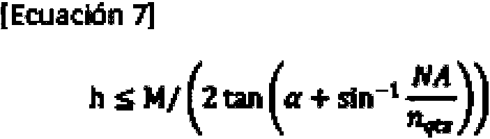
En la [Ecuación 7], "M" representa un diámetro del núcleo de una parte del extremo proximal (cuerpo principal de la fibra óptica) de la parte de convergencia del rayo láser, "NA" representa una apertura numérica del cuerpo principal de la fibra óptica, y "nqtz" representa un índice de refracción del núcleo de la fibra óptica.In [Equation 7], "M" represents a core diameter of a proximal end part (optical fiber main body) of the laser beam converging part, "NA" represents a numerical aperture of the main body of the laser beam. optical fiber, and "nqtz" represents a refractive index of the optical fiber core.
Cuando la altura "h" no satisface la [Ecuación 7], el rayo láser de pulso converge dentro de la fibra óptica 11 y existe el riesgo de destruir la fibra óptica 11. Por ejemplo, cuando el diámetro del núcleo M de la fibra óptica que se va a utilizar es de 400 μm, a es de 30°, la apertura numérica NA es de 0,22 y el índice de refracción nqtz del núcleo es de 1,437, el límite superior de la altura "h" es de 0,3 mm o menos, preferiblemente de 0,28 mm o menos, y con particular preferencia de 0,25 mm o menos.When the height "h" does not satisfy [Equation 7], the pulse laser beam converges inside the optical fiber 11 and there is a risk of destroying the optical fiber 11. For example, when the core diameter M of the optical fiber to be used is 400 μm, a is 30°, the numerical aperture NA is 0.22, and the refractive index nqtz of the core is 1.437, the upper limit of the height "h" is 0, 3 mm or less, preferably 0.28 mm or less, and particularly preferably 0.25 mm or less.
Por el contrario, cuando la altura "h" es demasiado pequeña, el rayo láser de pulso no puede enfocarse lo suficiente para obtener una gran onda de choque. Un límite inferior de la altura "h" es diferente dependiendo de la condición de la fibra óptica, pero generalmente es de 0,01 mm o más, preferiblemente de 0,05 mm o más, y con particular preferencia de 0,15 mm o más.On the contrary, when the height "h" is too small, the pulsed laser beam cannot be focused enough to obtain a large shock wave. A lower limit of the height "h" is different depending on the condition of the optical fiber, but it is generally 0.01 mm or more, preferably 0.05 mm or more, and particularly preferably 0.15 mm or more. further.
Volviendo a la Figura 1, en el dispositivo generador de ondas de choque 10 según la presente invención, la fibra óptica 11 tiene el extremo distal (parte final en el lado de emisión del rayo láser de pulso) dispuesto en el lado trasero (lado derecho en la Figura 1) del punto focal F de la superficie cóncava 21 en la parte reflectante 12. Se prefiere particularmente que el extremo distal esté dispuesto de manera que la distancia Lx entre el extremo distal de la parte de convergencia del rayo láser 17 y el punto focal F satisfagan las siguientes [Ecuación 1] y [Ecuación 2]:Returning to Fig. 1, in the shock wave generating device 10 according to the present invention, the optical fiber 11 has the distal end (end part on the emitting side of the pulsed laser beam) arranged on the rear side (right side). in Figure 1) of the focal point F of the concave surface 21 on the reflective part 12. It is particularly preferred that the distal end is arranged so that the distance Lx between the distal end of the converging part of the laser beam 17 and the focal point F satisfy the following [Equation 1] and [Equation 2]:

siempre que, en la [Ecuación 2], "a" represente un ángulo formado por el trapezoide isósceles expresado por la sección transversal en una dirección axial de la parte de convergencia del rayo láser, "nqtz" represente un índice de refracción del núcleo de la fibra óptica, "nliq" represente un índice de refracción del líquido, "NA" represente una apertura numérica de la fibra óptica, "M" represente un diámetro de núcleo en la parte del extremo proximal de la parte de convergencia del rayo láser y "h" represente una altura del cono truncado de la parte de convergencia del rayo láser.provided that, in [Equation 2], "a" represents an angle formed by the isosceles trapezoid expressed by the cross section in an axial direction of the converging part of the laser beam, "nqtz" represents a refractive index of the nucleus of the optical fiber, "nliq" represents a refractive index of the liquid, "NA" represents a numerical aperture of the optical fiber, "M" represents a core diameter at the proximal end portion of the convergence portion of the laser beam, and "h" represents a height of the frustum of the converging part of the laser beam.
Aquí, la Condición (I) en la "Ecuación 2" es una condición en la que todo el rayo láser de pulso es reflejado totalmente por los lados (superficie inclinada) 17b de la parte de convergencia del rayo láser 17.Here, Condition (I) in "Equation 2" is a condition in which the entire pulse laser beam is fully reflected by the sides (inclined surface) 17b of the laser beam converging part 17.
Específicamente, como se ilustra en la Figura 3(a), un rayo láser de pulso L1 que se desplaza dentro de la fibra óptica 11 que tiene la apertura numérica NA con un ángulo crítico 01, y que ingresa a los lados 17b de la parte de convergencia del rayo láser 17 en un ángulo de incidencia 0min (0.5rc-(0.5a+01)) se refleja totalmente. Esta condición se expresa de la siguiente manera: Specifically, as illustrated in Figure 3(a), a pulsed laser beam L1 traveling inside the optical fiber 11 having the numerical aperture NA with critical angle 01, and entering the sides 17b of the part of convergence of the laser beam 17 at an angle of incidence 0min (0.5rc-(0.5a+01)) is totally reflected. This condition is expressed as follows:

, lo que resulta en que:, which results in:

Además, la siguiente [Ecuación 10] expresa un valor teórico de una distancia "d" (d1 en la Figura 3 (a)) entre un punto de enfoque obtenido cuando, bajo la condición, el rayo láser de pulso L1' totalmente reflejado se irradia desde el extremo distal de la parte de convergencia del rayo láser 17, y el láser de pulso irradiado L1" se enfoca frente a la parte de convergencia del rayo láser 17 y el extremo distal de la parte de convergencia del rayo láser 17.In addition, the following [Equation 10] expresses a theoretical value of a distance "d" (d1 in Figure 3(a)) between a focus point obtained when, under the condition, the fully reflected pulse laser beam L1' is radiates from the distal end of the laser beam convergence portion 17, and the irradiated pulse laser L1" is focused in front of the laser beam convergence portion 17 and the distal end of the laser beam convergence portion 17.

Bajo la Condición (I), todo el rayo láser de pulso se refleja totalmente dentro de la parte de convergencia del rayo láser 17 y, por lo tanto, la pérdida de energía es la más pequeña en comparación con las Condiciones (II) y (III). Under Condition (I), the entire pulsed laser beam is totally reflected within the convergence part of the laser beam 17 and therefore the energy loss is the smallest compared to Conditions (II) and ( III).
La Condición (II) en la "Ecuación 2" es una condición en la que una parte del rayo láser de pulso se refleja totalmente por los lados (superficie inclinada) 17b de la parte de convergencia del rayo láser 17, y la otra parte del mismo se transmite.Condition (II) in "Equation 2" is a condition in which a part of the pulsed laser beam is fully reflected by the sides (inclined surface) 17b of the laser beam converging part 17, and the other part of the itself is transmitted.
Específicamente, como se ilustra en la Figura 3(a), se transmite un rayo láser de pulso L1 que se desplaza dentro de la fibra óptica 11 que tiene la apertura numérica NA con un ángulo crítico 01, y que ingresa a los lados 17b de la parte de convergencia del rayo láser 17 en un ángulo de incidencia 0min (0.5rc-(0.5a+01)). Esta condición se expresa de la siguiente manera:Specifically, as illustrated in Figure 3(a), a pulsed laser beam L1 is transmitted traveling inside the optical fiber 11 having the numerical aperture NA with critical angle 01, and entering the sides 17b of the convergence part of the laser beam 17 at an angle of incidence 0min (0.5rc-(0.5a+01)). This condition is expressed as follows:

, lo que resulta en que:, which results in:

Además, como se ilustra en la Figura 3(b), un rayo láser de pulso L2 (ángulo de incidencia 0par) que se desplaza por el interior de la fibra óptica 11 en paralelo al eje de la misma se refleja totalmente. Esta condición se expresa de la siguiente manera: Furthermore, as illustrated in Fig. 3(b), a pulsed laser beam L2 (incidence angle 0 par) traveling inside the optical fiber 11 parallel to the axis thereof is fully reflected. This condition is expressed as follows:

En otras palabras, el rayo láser de pulso que ingresa a los lados 17b de la parte de convergencia del rayo láser 17 en un ángulo de incidencia que es mayor que un ángulo 0m¡n (0.5rc-(0.5a+9i)) y es menor que un ángulo 0par (0.5rc-0.5a) se transmite a través de los lados 17b de la parte de convergencia del rayo láser 17, y el rayo láser de pulso que ingresa a los lados 17b en un ángulo de incidencia que es el ángulo 9par (0.5rc-0.5a) o más es reflejado totalmente por los lados 17b de la parte de convergencia del rayo láser 17.In other words, the pulsed laser beam entering the sides 17b of the converging part of the laser beam 17 at an angle of incidence that is greater than an angle 0min(0.5rc-(0.5a+9i)) and is less than an angle 0par (0.5rc-0.5a) is transmitted through the sides 17b of the converging part of the laser beam 17, and the pulse laser beam entering the sides 17b at an angle of incidence that is the angle 9even (0.5rc-0.5a) or more is fully reflected by the sides 17b of the converging part of the laser beam 17.
Además, la siguiente [Ecuación 14] expresa un valor teórico de una distancia "d" (d2 en la Figura 3(b)) entre un punto de enfoque obtenido cuando, bajo la condición, la parte totalmente reflejada del rayo láser de pulso L2' se irradia desde el extremo distal de la parte de convergencia del rayo láser 17, y el rayo láser de pulso irradiado L2" se enfoca frente a la parte de convergencia del rayo láser 17 y el extremo distal de la parte de convergencia del rayo láser 17.In addition, the following [Equation 14] expresses a theoretical value of a distance "d" (d2 in Figure 3(b)) between a focus point obtained when, under the condition, the fully reflected part of the pulse laser beam L2 ' is irradiated from the distal end of the laser beam converging part 17, and the irradiated pulse laser beam L2" is focused in front of the laser beam converging part 17 and the distal end of the laser beam converging part 17.

Se ha confirmado experimentalmente que, bajo la Condición (II), a medida que aumenta el ángulo de conicidad a de la parte de convergencia del rayo láser 17, la reflexión total del rayo láser de pulso en los lados 17b de la parte de convergencia del rayo láser 17 se reduce abruptamente, y el efecto del rayo láser de pulso transmitido a través de la parte de convergencia del rayo láser 17 se vuelve más significativo. Por lo tanto, en la Condición (II), se prefiere que el ángulo de conicidad a de la parte de convergencia del rayo láser 17 sea de 50° o menos, preferiblemente de 45° o menos, y con particular preferencia de 40° o menos.It has been confirmed experimentally that, under Condition (II), as the taper angle a of the converging part of the laser beam 17 increases, the total reflection of the pulsed laser beam at the sides 17b of the converging part of the laser beam 17 is abruptly reduced, and the effect of the pulsed laser beam transmitted through the converging part of the laser beam 17 becomes more significant. Therefore, in Condition (II), it is preferred that the taper angle a of the converging part of the laser beam 17 is 50° or less, preferably 45° or less, and particularly preferably 40° or less. less.
De las relaciones antes mencionadas, se considera que, cuando la distancia Lx entre la parte de convergencia del rayo láser 17 y el punto focal F coincide con el valor teórico "d" en las Condiciones (I) y (II) de la "Ecuación 2", es decir, cuando la relación: Lx=d está establecida, la onda de choque reflejada por la superficie cóncava 21 puede converger a un punto fuera de la parte reflectante 12, y puede maximizarse una sobrepresión máxima Pmax de la onda de choque. Sin embargo, cabe señalar que en un dispositivo generador de ondas de choque 10, debido a los efectos tales como el tipo de rayo láser de pulso que se utilizará, las características del cuerpo de sellado 23 y una absorbancia del líquido 24, la sobrepresión máxima Pmax no se maximiza necesariamente cuando la relación: Lx=d está establecida. Además, en la Condición (II) de la "Ecuación 2", también están los efectos de la parte del rayo láser de pulso transmitido a través de la parte de convergencia del rayo láser 17. Por lo tanto, se prefiere que la posición del extremo distal de la parte de convergencia del rayo láser 17 se ajuste adecuadamente alrededor de la posición en la que Lx=d. Los inventores de la presente invención han confirmado experimentalmente que, en la Condición (I), en un rango en el que la distancia Lx es mayor que 0 veces el valor teórico "d", es preferiblemente 0,4 veces el valor teórico "d" o más, y es más preferiblemente 0,5 veces el valor teórico "d" o más, y la distancia Lx es 1,5 veces el valor teórico "d" o menos, preferiblemente 1,4 veces el valor teórico "d" o menos, y más preferiblemente 1,2 veces el valor teórico "d" o menos, se obtiene el valor máximo de la sobrepresión máxima Pmax. Los inventores de la presente invención también han confirmado experimentalmente que, en la Condición (II), en un rango en el que la distancia Lx es mayor que 0 veces el valor teórico "d", es preferiblemente 0,4 veces el valor teórico "d" o más, y es más preferiblemente 0,5 veces el valor teórico "d" o más, y la distancia Lx es 1,5 veces el valor teórico "d" o menos, preferiblemente 1,3 veces el valor teórico "d" o menos, y más preferiblemente 1,2 veces el valor teórico "d" o menos, se obtiene el valor máximo de la sobrepresión máxima Pmax.From the aforementioned relationships, it is considered that, when the distance Lx between the convergence part of the laser beam 17 and the focal point F coincides with the theoretical value "d" in Conditions (I) and (II) of "Equation 2", that is, when the relationship: Lx=d is established, the shock wave reflected by the concave surface 21 can converge to a point outside the reflecting part 12, and a maximum overpressure Pmax of the shock wave can be maximized. . However, it should be noted that in a shock wave generating device 10, due to effects such as the type of pulsed laser beam to be used, the characteristics of the sealing body 23 and an absorbance of the liquid 24, the maximum overpressure Pmax is not necessarily maximized when the relationship: Lx=d is established. In addition, in Condition (II) of "Equation 2", there are also the effects of the part of the pulsed laser beam transmitted through the converging part of the laser beam 17. Therefore, it is preferred that the position of the distal end of the laser beam converging portion 17 fits properly around the position where Lx=d. The inventors of the present invention have experimentally confirmed that, in Condition (I), in a range in which the distance Lx is greater than 0 times the theoretical value "d", it is preferably 0.4 times the theoretical value "d " or more, and is more preferably 0.5 times the theoretical value "d" or more, and the distance Lx is 1.5 times the theoretical value "d" or less, preferably 1.4 times the theoretical value "d" or less, and more preferably 1.2 times the theoretical value "d" or less, the maximum value of the maximum overpressure Pmax is obtained. The inventors of the present invention have also experimentally confirmed that, in Condition (II), in a range in which the distance Lx is greater than 0 times the theoretical value "d", it is preferably 0.4 times the theoretical value " d" or more, and is more preferably 0.5 times the theoretical value "d" or more, and the distance Lx is 1.5 times the theoretical value "d" or less, preferably 1.3 times the theoretical value "d" " or less, and more preferably 1.2 times the theoretical value "d" or less, the maximum value of the maximum overpressure Pmax is obtained.
Las Condiciones (I) y (II) en la "Ecuación 2" son condiciones en las que se enfoca el rayo láser de pulso reflejado totalmente en la parte de convergencia del rayo láser 17. Mientras tanto, los inventores de la presente invención han confirmado experimentalmente que el rayo láser de pulso transmitido a través de la parte de convergencia del rayo láser 17 también se enfoca frente a la parte de convergencia del rayo láser 17. Por lo tanto, el extremo distal puede disponerse de manera que la distancia Lx entre el extremo distal de la parte de convergencia del rayo láser 17 y el punto focal F satisfaga las siguientes [Ecuación 3] y [Ecuación 4]: Conditions (I) and (II) in "Equation 2" are conditions in which the fully reflected pulse laser beam is focused on the converging part of the laser beam 17. Meanwhile, the inventors of the present invention have confirmed experimentally that the pulsed laser beam transmitted through the converging part of the laser beam 17 is also focused in front of the converging part of the laser beam 17. Therefore, the distal end can be arranged so that the distance Lx between the distal end of the converging part of the laser beam 17 and the focal point F satisfy the following [Equation 3] and [Equation 4]:

siempre que, en la [Ecuación 4], "a" represente un ángulo formado por el trapezoide isósceles expresado por la sección transversal en una dirección axial de la parte de convergencia del rayo láser, "nqtz" represente un índice de refracción del núcleo de la fibra óptica, "nliq" represente un índice de refracción del líquido, "NA" represente una apertura numérica de la fibra óptica, "M" represente un diámetro de núcleo en una parte del extremo proximal de la parte de convergencia del rayo láser y "h" represente una altura del cono truncado de la parte de convergencia del rayo láser.provided that, in [Equation 4], "a" represents an angle formed by the isosceles trapezoid expressed by the cross section in an axial direction of the converging part of the laser beam, "nqtz" represents a refractive index of the nucleus of the optical fiber, "nliq" represents a refractive index of the liquid, "NA" represents a numerical aperture of the optical fiber, "M" represents a core diameter at a proximal end part of the converging part of the laser beam, and "h" represents a height of the frustum of the converging part of the laser beam.
La Condición (III) en la "Ecuación 4" es una condición en la que sustancialmente todo el rayo láser de pulso se transmite a través de los lados 17b de la parte 17 de convergencia del rayo láser.Condition (III) in "Equation 4" is a condition in which substantially all of the pulsed laser beam is transmitted through the sides 17b of the laser beam converging part 17.
Específicamente, como se ilustra en la Figura 3(c), se transmite el rayo láser de pulso L2 (ángulo de incidencia 0par) que se desplaza por el interior de la fibra óptica 11 en paralelo al eje de la misma. Esta condición se expresa de la siguiente manera:Specifically, as illustrated in Figure 3(c), the pulsed laser beam L2 (incidence angle 0 par) is transmitted and travels inside the optical fiber 11 parallel to the axis thereof. This condition is expressed as follows:

Además, como se ilustra en la Figura 3(d), un rayo láser de pulso L3 que se desplaza dentro de la fibra óptica 11 que tiene la apertura numérica NA con un ángulo crítico 01, y que ingresa a los lados 17b de la parte de convergencia del rayo láser 17 en un ángulo de incidencia 0max (0.5rc-(0.5a-01)) se refleja totalmente. Esta condición se expresa de la siguiente manera.Furthermore, as illustrated in Figure 3(d), a pulse laser beam L3 traveling inside the optical fiber 11 having numerical aperture NA with critical angle 01, and entering the sides 17b of the part of convergence of the laser beam 17 at an angle of incidence 0max (0.5rc-(0.5a-01)) is totally reflected. This condition is expressed as follows.

Es decir, solo el rayo láser de pulso que ingresa a los lados 17b de la parte de convergencia del rayo láser 17 en un ángulo de incidencia de un ángulo 0max (0.5rc-(0.5a-01)) es reflejado totalmente por los lados 17b de la parte de convergencia del rayo láser 17, y se transmiten otros rayos.That is, only the pulse laser beam entering the sides 17b of the convergence part of the laser beam 17 at an angle of incidence of an angle 0max (0.5rc-(0.5a-01)) is totally reflected by the sides. 17b of the converging part of the laser beam 17, and other beams are transmitted.
Además, la siguiente [Ecuación 15] expresa un valor teórico de una distancia "d" (d3 en la Figura 3(c)) entre un punto de enfoque obtenido cuando, bajo la condición, el rayo láser de pulso L2''' transmitido a través de los lados 17b de la parte de convergencia del rayo láser 17 se enfoca, y el extremo distal de la parte de convergencia del rayo láser 17. In addition, the following [Equation 15] expresses a theoretical value of a distance "d" (d3 in Figure 3(c)) between a focus point obtained when, under the condition, the transmitted pulse laser beam L2''' through the sides 17b of the converging part of the laser beam 17 is focused, and the distal end of the converging part of the laser beam 17.

También bajo la Condición (III) de la "Ecuación 4", se considera que, cuando la distancia Lx entre la parte 17 de convergencia del rayo láser y el punto focal F coincide con el valor teórico "d", es decir, cuando la relación: Lx=d está establecida, la onda de choque reflejada por la superficie cóncava 21 puede converger a un punto fuera de la parte reflectante 12, y puede maximizarse la sobrepresión máxima Pmax de la onda de choque. Sin embargo, cabe señalar que, también en este caso, en un dispositivo generador de ondas de choque 10, debido a los efectos tales como el tipo de rayo láser de pulso que se utilizará, las características del cuerpo de sellado 23 y la absorbancia del líquido 24, la sobrepresión máxima Pmax no se maximiza necesariamente cuando la relación: Lx=d está establecida. Además, en la Condición (III) de la "Ecuación 4", también están los efectos del rayo láser de pulso particular reflejado totalmente por la parte de convergencia del rayo láser 17. Por lo tanto, se prefiere que la posición del extremo distal de la parte de convergencia del rayo láser 17 se ajuste adecuadamente alrededor de la posición en la que Lx=d. Los inventores de la presente invención han confirmado experimentalmente que, en el caso de la Condición (III), en un rango en el que la distancia Lx es mayor que 0 como el valor teórico "d", es preferiblemente 0,5 veces el valor teórico "d" o más, y es más preferiblemente 0,7 veces el valor teórico "d" o más, y la distancia Lx es 2,4 veces el valor teórico "d" o menos, preferiblemente 1,75 veces el valor teórico "d" o menos, y más preferiblemente 1,6 veces el valor teórico "d" o menos, se obtiene el valor máximo de la sobrepresión máxima Pmax. Also under Condition (III) of "Equation 4", it is considered that when the distance Lx between the convergence part 17 of the laser beam and the focal point F coincides with the theoretical value "d", that is, when the relation: Lx=d is established, the shock wave reflected by the concave surface 21 can converge to a point outside the reflective part 12, and the maximum overpressure Pmax of the shock wave can be maximized. However, it should be noted that, also in this case, in a shock wave generating device 10, due to effects such as the type of pulsed laser beam to be used, the characteristics of the sealing body 23 and the absorbance of the liquid 24, the maximum overpressure Pmax is not necessarily maximized when the relationship: Lx=d is established. In addition, in Condition (III) of "Equation 4", there are also the effects of the particular pulsed laser beam totally reflected by the converging part of the laser beam 17. Therefore, it is preferred that the position of the distal end of the converging part of the laser beam 17 fits properly around the position where Lx=d. The inventors of the present invention have experimentally confirmed that, in the case of Condition (III), in a range in which the distance Lx is greater than 0 as the theoretical value "d", it is preferably 0.5 times the value theoretical value "d" or more, and is more preferably 0.7 times the theoretical value "d" or more, and the distance Lx is 2.4 times the theoretical value "d" or less, preferably 1.75 times the theoretical value "d" or less, and more preferably 1.6 times the theoretical value "d" or less, the maximum value of the maximum overpressure Pmax is obtained.
Como se ha descrito anteriormente, el dispositivo generador de ondas de choque 10 según la presente invención está configurado para irradiar el líquido con el rayo láser de pulso a través de la fibra óptica de manera que un punto central C de la onda de choque generada en el líquido coincida con el punto focal F de la superficie cóncava 21, o se ubique muy cerca del punto focal F de la superficie cóncava 21. Por lo tanto, la onda de choque reflejada por la superficie cóncava 21 puede converger eficazmente en un punto fuera de la parte reflectante 12, y la sobrepresión máxima Pmax de la onda de choque puede aumentar drásticamente.As described above, the shock wave generating device 10 according to the present invention is configured to irradiate the liquid with the pulsed laser beam through the optical fiber so that a central point C of the shock wave generated in the liquid coincides with the focal point F of the concave surface 21, or is located very close to the focal point F of the concave surface 21. Therefore, the shock wave reflected by the concave surface 21 can effectively converge on a point outside of the reflective part 12, and the maximum overpressure Pmax of the shock wave can increase dramatically.
A continuación, se describe la parte reflectante 12. La parte reflectante 12 tiene un aspecto cilíndrico e incluye el reflector 20, el cuerpo de sellado 23 y el líquido 24. El reflector 20 tiene la superficie cóncava 21 formada en el lado frontal. La parte de abertura de la superficie cóncava 21 está sellada por el cuerpo de sellado 23 con el líquido 24 cargado. Además, el reflector 20 tiene el orificio pasante 22 formado coaxialmente con un eje central del reflector 20 desde el lado trasero hacia la superficie cóncava 21. De esta manera, la parte reflectante 12 tiene una estructura simple y se puede reducir su tamaño y, por lo tanto, se puede unir fácilmente al extremo distal del catéter 14.Next, the reflective part 12 will be described. The reflective part 12 has a cylindrical appearance and includes the reflector 20, the sealing body 23 and the liquid 24. The reflector 20 has the concave surface 21 formed on the front side. The opening portion of the concave surface 21 is sealed by the sealing body 23 with the charged liquid 24. In addition, the reflector 20 has the through hole 22 formed coaxially with a central axis of the reflector 20 from the rear side toward the concave surface 21. In this way, the reflective part 12 has a simple structure and its size can be reduced, and thus Therefore, it can be easily attached to the distal end of the catheter 14.
La superficie cóncava 21 tiene una forma de superficie de revolución cortada obtenida al cortar una superficie de revolución con un plano perpendicular al eje de rotación o un plano que tiene un ángulo de inclinación, por ejemplo, de manera que un lado de dirección de propagación (lado frontal) de la onda de choque se abra. La superficie cóncava 21 es preferiblemente una superficie de revolución cortada obtenida al cortar la superficie de revolución con el plano perpendicular al eje de rotación. El eje de rotación de la superficie cóncava 21 es coaxial con el orificio pasante 22.The concave surface 21 has a cut surface of revolution shape obtained by cutting a surface of revolution with a plane perpendicular to the axis of rotation or a plane having an angle of inclination, for example, such that a propagation direction side ( front side) of the shock wave to open. The concave surface 21 is preferably a cut surface of revolution obtained by cutting the surface of revolution with the plane perpendicular to the axis of rotation. The axis of rotation of the concave surface 21 is coaxial with the through hole 22.
Como superficie de revolución, se ejemplifica una forma elipsoidal que satisface la [Ecuación 5] en la que un eje principal es el eje de rotación.As the surface of revolution, an ellipsoidal shape satisfying [Equation 5] in which a principal axis is the axis of rotation is exemplified.

Cuando la superficie cóncava 21 tiene una forma esferoidal cortada, el extremo distal de la parte de convergencia del rayo láser 17 de la fibra óptica 11 se dispone, en las coordenadas de la [Ecuación 5], en la siguiente posición:When the concave surface 21 has a cut spheroidal shape, the distal end of the converging part of the laser beam 17 of the optical fiber 11 is arranged, in the coordinates of [Equation 5], in the following position:

La forma elipsoidal expresada por la [Ecuación 5] tiene un diámetro menor "b" con un límite superior de 50 mm o menos, 10 mm o menos, preferiblemente 5 mm o menos, 3 mm o menos, y con particular preferencia 2,8 mm o menos. Se prefiere que el diámetro menor sea más pequeño porque el dispositivo generador de ondas de choque puede reducirse de tamaño. Sin embargo, cuando un punto convergente fuera de la parte reflectante 12 está demasiado cerca de la parte reflectante 12, un efecto del tratamiento se vuelve más pequeño y, por lo tanto, un límite inferior del diámetro menor "b" es de 1,0 mm o más, preferiblemente de 1,5 mm o más y con particular preferencia de 2,0 mm o más.The ellipsoidal shape expressed by [Equation 5] has a minor diameter "b" with an upper limit of 50mm or less, 10mm or less, preferably 5mm or less, 3mm or less, and particularly preferably 2.8 mm or less. It is preferred that the minor diameter is smaller because the shock wave generating device can be reduced in size. However, when a convergent point outside the reflective part 12 is too close to the reflective part 12, a treatment effect becomes smaller, and therefore a lower limit of the minor diameter "b" is 1.0 mm or more, preferably 1.5 mm or more, and particularly preferably 2.0 mm or more.
Una relación de los diámetros mayor y menor (a/b) de la forma elipsoidal expresada por la [Ecuación 5] es mayor que 1,2 y menor que 2,0, preferiblemente mayor que 1,3 y menor que 1,6, y con particular preferencia mayor que 1,4 y menor que 1,6. Cuando a/b es 2,0 o más, el ángulo de convergencia de la onda de choque se vuelve más superficial y una región de generación de alta presión tiene una forma que se alarga en la dirección axial. Por el contrario, cuando a/b es 1,2 o menos, la onda de choque presenta una fuerte convergencia, pero la longitud focal se vuelve desfavorablemente más corta.A ratio of the major and minor diameters (a/b) of the ellipsoidal shape expressed by [Equation 5] is greater than 1.2 and less than 2.0, preferably greater than 1.3 and less than 1.6, and with particular preference greater than 1.4 and less than 1.6. When a/b is 2.0 or more, the angle of convergence of the shock wave becomes shallower, and a high-pressure generating region has a shape elongating in the axial direction. On the contrary, when a/b is 1.2 or less, the shock wave exhibits strong convergence, but the focal length becomes unfavorably shorter.
Un límite superior de un diámetro externo del reflector 20 es de 75 mm o menos, preferiblemente de 10 mm o menos, 5 mm o menos, con particular preferencia de 3,5 mm o menos y 3 mm o menos. Por el contrario, un límite inferior del diámetro externo del reflector 20 es de 1,5 mm o más, preferiblemente de 2,5 mm o más y con particular preferencia de 2,5 mm o más. Cuando el diámetro externo del reflector 20 es superior a 75 mm, es difícil pasar el reflector 20 a través del catéter. Por el contrario, cuando el diámetro externo del reflector 20 es inferior a 1,5 mm, resulta difícil generar una superficie cóncava que sea suficiente para reflejar y converger la onda de choque.An upper limit of an external diameter of the reflector 20 is 75 mm or less, preferably 10 mm or less, 5 mm or less, particularly preferably 3.5 mm or less, and 3 mm or less. On the contrary, a lower limit of the external diameter of the reflector 20 is 1.5 mm or more, preferably 2.5 mm or more, and particularly preferably 2.5 mm or more. When the outer diameter of the reflector 20 is greater than 75mm, it is difficult to pass the reflector 20 through the catheter. On the contrary, when the external diameter of the reflector 20 is less than 1.5 mm, it becomes difficult to generate a concave surface that is sufficient to reflect and converge the shock wave.
El material del reflector 20 no está particularmente limitado, y los ejemplos del mismo incluyen resinas acrílicas y otras resinas sintéticas, y latón, acero inoxidable y otros metales. Cuando se utiliza un metal, la superficie cóncava 21 del reflector 20 puede tener un acabado de espejo para aumentar la reflectancia de la onda de choque. Además, el metal y el líquido tienen una gran diferencia en la impedancia acústica y, por lo tanto, también pueden aumentar la reflectancia de la onda de choque. Mientras tanto, cuando se utiliza una resina sintética, se obtienen ventajas, por ejemplo, una excelente trabajabilidad. Mediante la formación de una película metálica en la superficie cóncava 21 del reflector 20 por la formación de revestimientos metálicos, por ejemplo, se puede aumentar la reflectancia de la onda de choque.The material of the reflector 20 is not particularly limited, and examples thereof include acrylic resins and other synthetic resins, and brass, stainless steel and other metals. When a metal is used, the concave surface 21 of the reflector 20 may have a mirror finish to increase the reflectance of the shock wave. Also, metal and liquid have a large difference in acoustic impedance and therefore can also increase the reflectance of the shock wave. Meanwhile, when a synthetic resin is used, advantages are obtained, for example, excellent workability. By the formation of a metallic film on the concave surface 21 of the reflector 20 by the formation of metallic coatings, for example, the reflectance of the shock wave can be increased.
Se requiere que el orificio pasante 22 se ajuste en tamaño (diámetro interno) según corresponda dependiendo del diámetro externo de la fibra óptica 11 que se va a utilizar.The through hole 22 is required to be adjusted in size (internal diameter) accordingly depending on the external diameter of the optical fiber 11 to be used.
Para el cuerpo de sellado 23, se puede utilizar una película delgada conocida hecha de una resina sintética que tenga elasticidad. Por ejemplo, se puede utilizar una película delgada hecha de polietileno, polipropileno, tereftalato de polietileno u otra resina, o vinilmetilsilicona, metilsilicona, fenilmetilsilicona u otro caucho de silicona. El grosor de la película delgada se selecciona según corresponda dependiendo de su material y, en general, es preferiblemente de 0,05 mm a 0,20 mm, y más preferiblemente de 0,10 mm a 0,17 mm.For the sealing body 23, a known thin film made of a synthetic resin having elasticity can be used. For example, a thin film made of polyethylene, polypropylene, polyethylene terephthalate or other resin, or vinylmethylsilicone, methylsilicone, phenylmethylsilicone or other silicone rubber can be used. The thickness of the thin film is selected as appropriate depending on its material, and is generally preferably 0.05 mm to 0.20 mm, and more preferably 0.10 mm to 0.17 mm.
Además, el líquido 24 es un líquido conocido. Ejemplos de los mismos incluyen agua y solución salina, y el líquido 24 es preferiblemente agua pura, y con particular preferencia agua ultrapura desgasificada al vacío. El índice de refracción del líquido 24 es inferior al del núcleo de la fibra óptica, y es concretamente de 1,0 a 1,5, y preferiblemente de 1,3 a 1,4.Furthermore, the liquid 24 is a known liquid. Examples thereof include water and saline, and liquid 24 is preferably pure water, and particularly preferably vacuum degassed ultrapure water. The refractive index of the liquid 24 is less than that of the optical fiber core, and is specifically 1.0 to 1.5, and preferably 1.3 to 1.4.
Para perfundir un espacio formado entre la superficie cóncava 21 y el cuerpo de sellado 23 con el líquido 24, se puede proporcionar una estructura de tuberías configurada para comunicarse entre el suministro de agua y las tuberías de descarga de agua (no mostradas) y el espacio. Como estructura de tuberías, aunque sin limitación particular, se puede utilizar una estructura de tuberías que incluye, según se ilustra en la Figura 4(a) a la Figura 4(g), una parte de conexión de tubería de suministro de agua 31 conectada a la tubería de suministro de agua y una parte de conexión de tubería de descarga de agua 32 conectada a la tubería de descarga de agua. En la Figura 4(a) y en la Figura 4(b), el diámetro de la parte frontal 22a del orificio pasante 22 es mayor que el diámetro de la fibra óptica 11 (entre 2 y 3 veces el diámetro de la fibra óptica 11) en el lado de la superficie cóncava 21, y la parte de conexión de la tubería de suministro de agua 31 y la parte de conexión de la tubería de descarga de agua 32 están formadas de manera que se ramifican a partir del orificio pasante 22. Además, en la Figura 4(c) a la Figura 4(e), el diámetro del orificio pasante 22 es similarmente mayor que el diámetro de la fibra óptica 11 en el lado de la superficie cóncava 21, y la parte de conexión de la tubería de suministro de agua 31 y la parte de conexión de la tubería de descarga de agua 32 están formadas de manera que se ramifican a partir del orificio pasante 22. Además, se proporciona un elemento de fijación 33 configurado para fijar la fibra óptica 11. Además, el orificio pasante 22 está separado de la parte de conexión de la tubería de suministro de agua 31 y la parte de conexión de la tubería de descarga de agua 32 por el elemento de fijación 33. Incluso, en la Figura 4(f) y la Figura 4(g), la parte de conexión de la tubería de suministro de agua 31 y la parte de conexión de la tubería de descarga de agua 32 se forman por separado del orificio pasante 22.In order to perfuse a space formed between the concave surface 21 and the sealing body 23 with the liquid 24, a piping structure configured to communicate between the water supply and discharge water pipes (not shown) and the space may be provided. . As the piping structure, but without particular limitation, a piping structure can be used including, as illustrated in Fig. 4(a) to Fig. 4(g), a water supply pipe connection part 31 connected to the water supply pipe and a water discharge pipe connecting part 32 connected to the water discharge pipe. In Figure 4(a) and Figure 4(b), the diameter of the front part 22a of the through hole 22 is greater than the diameter of the optical fiber 11 (between 2 and 3 times the diameter of the optical fiber 11 ) on the concave surface 21 side, and the water supply pipe connection part 31 and the water discharge pipe connection part 32 are formed so as to branch out from the through hole 22. In addition, in Figure 4(c) to Figure 4(e), the diameter of the through hole 22 is similarly larger than the diameter of the optical fiber 11 on the side of the concave surface 21, and the connecting part of the water supply pipe 31 and the water discharge pipe connection part 32 are formed to branch from the through hole 22. In addition, a fixing member 33 configured to fix the optical fiber 11 is provided. In addition, the through hole 22 is separated from the water supply pipe connection part 31 and the water discharge pipe connection part 32 by the fixing member 33. Even in Fig. 4(f) and Fig. 4(g), the water supply pipe connection part 31 and the water discharge pipe connection part 32 are formed separately from the through hole 22.
Como se describió anteriormente, en el dispositivo generador de ondas de choque 10, el extremo distal de la parte de convergencia del rayo láser 17 de la fibra óptica 11 se fija en la posición a la distancia Lx en el lado trasero del punto focal F dentro de la superficie cóncava 21. Por lo tanto, cuando el rayo láser de pulso se irradia desde el extremo distal de la parte de convergencia del rayo láser 17 para generar la onda de choque en el líquido 24 dentro de la superficie cóncava 21, el punto central C de la onda de choque y el punto focal F pueden hacerse coincidir sustancialmente entre sí, y la onda de choque reflejada por la superficie cóncava 21 puede converger eficazmente en un punto fuera de la parte reflectante 12. As described above, in the shock wave generating device 10, the distal end of the laser beam converging part 17 of the optical fiber 11 is fixed at the position at the distance Lx on the rear side of the focal point F within of the concave surface 21. Therefore, when the pulsed laser beam is irradiated from the distal end of the converging part of the laser beam 17 to generate the shock wave in the liquid 24 inside the concave surface 21, the point The shock wave center C and the focal point F can be substantially coincident with each other, and the shock wave reflected by the concave surface 21 can effectively converge to a point outside the reflecting part 12.
2. Segunda realización2. Second realization
A continuación, se describe un dispositivo generador de ondas de choque 10 según una segunda realización de la presente invención. En esta realización, la superficie cóncava 21 tiene una forma de superficie de revolución cortada obtenida al cortar una superficie curvada obtenida modificando el esferoide descrito anteriormente. Los demás componentes son los mismos que los de la primera realización.Next, a shock wave generating device 10 according to a second embodiment of the present invention will be described. In this embodiment, the concave surface 21 has a cut revolution surface shape obtained by cutting a curved surface obtained by modifying the spheroid described above. The other components are the same as those of the first embodiment.
Como se describió anteriormente, un frente de onda de la onda de choque generada por el dispositivo generador de ondas de choque 10 se distorsiona, por ejemplo, se hincha desde una dirección de emisión de láser hacia atrás, para ser asférica. Por lo tanto, cuando la superficie cóncava 21 tiene una forma de superficie de revolución cortada obtenida al cortar el esferoide como en la primera realización, se producen diferencias en la distancia de propagación en la que la onda de choque reflejada en diferentes partes de la superficie cóncava 21 converge en un punto fuera de la parte reflectante 12, y se hace difícil reflejar y converger eficazmente la onda de choque. En tal caso, para igualar las distancias de propagación de la onda de choque, se prefiere utilizar, para la superficie cóncava 21, una forma de superficie de revolución cortada obtenida al cortar la superficie curvada obtenida modificando el esferoide.As described above, a wavefront of the shock wave generated by the shock wave generating device 10 is distorted, for example, swelled from a laser emission direction backwards, to be aspherical. Therefore, when the concave surface 21 has a cut revolution surface shape obtained by cutting the spheroid as in the first embodiment, there are differences in the propagation distance in which the shock wave reflected from different parts of the surface concave 21 converges to a point outside the reflecting part 12, and it becomes difficult to effectively reflect and converge the shock wave. In such a case, in order to equalize the propagation distances of the shock wave, it is preferred to use, for the concave surface 21, a cut revolution surface shape obtained by cutting the curved surface obtained by modifying the spheroid.
La modificación del esferoide no está particularmente limitada siempre que la onda de choque generada pueda reflejarse de eficazmente y converger en un punto fuera de la parte reflectante 12. Por ejemplo, el dispositivo generador de ondas de choque se puede producir realmente, y el esferoide se puede modificar en base a los datos experimentales obtenidos del mismo, o se puede modificar en base a los resultados de la simulación mediante un ordenador. Sin embargo, cabe señalar que cuando se considera fabricar industrialmente el dispositivo generador de ondas de choque, se desea que el esferoide se modifique en base a las siguientes [Ecuación 5] y [Ecuación 6]. The modification of the spheroid is not particularly limited as long as the generated shock wave can be effectively reflected and converged to a point outside the reflecting part 12. For example, the shock wave generating device can be actually produced, and the spheroid can be it can be modified based on the experimental data obtained therefrom, or it can be modified based on the results of simulation by a computer. However, it should be noted that when considering manufacturing the shock wave generating device industrially, it is desired that the spheroid be modified based on the following [Equation 5] and [Equation 6].
Es decir, se prefiere utilizar, como superficie cóncava 21, una superficie de revolución cortada obtenida al cortar la superficie curva obtenida al girar una forma (x1, y1) determinada por la [Ecuación 5] y [Ecuación 6] con el eje principal de la elipse expresada por la [Ecuación 5] siendo el eje de rotación,That is, it is preferred to use, as the concave surface 21, a cut surface of revolution obtained by cutting the curved surface obtained by rotating a shape (x 1 , y 1 ) determined by [Equation 5] and [Equation 6] with the axis principal of the ellipse expressed by [Equation 5] being the axis of rotation,

siempre que, en la [Ecuación 6], "9" represente, cuando un frente de onda de la onda de choque en un momento determinado esté representado por S, un frente de onda de la onda de choque ideal suponiendo que la onda de choque que es completamente esférica esté representada por I, un punto central de la onda de choque ideal esté representado por C, y un punto en el frente de onda S y el frente de onda I que está situado en una prolongación de un eje central de la fibra óptica esté representado por Sf, un ángulo alrededor del punto central C con respecto a una línea que conecta el punto central C y el punto Sf, y "AD" represente, cuando los puntos de intersección de una línea recta en dirección radial de la onda de choque ideal que pasa por el punto central C y tiene un ángulo central de 0, y el frente de onda S y el frente de onda I estén representados por S0 e I0, respectivamente, una distancia entre el punto de intersección S0 y el punto de intersección I0.provided that, in [Equation 6], "9" represents, when a wavefront of the shock wave at a given time is represented by S, a wavefront of the ideal shock wave assuming that the shock wave that is completely spherical is represented by I, a central point of the ideal shock wave is represented by C, and a point on the S wave front and the I wave front that lies in a prolongation of a central axis of the optical fiber is represented by Sf, an angle around the center point C with respect to a line connecting the center point C and the point Sf, and "AD" represents, when the points of intersection of a straight line in the radial direction of the ideal shock wave that passes through the central point C and has a central angle of 0, and the wavefront S and the wavefront I are represented by S0 and I0, respectively, a distance between the intersection point S0 and the intersection point I0.
Mediante la modificación del esferoide como se ha descrito anteriormente, se pueden igualar las distancias de propagación a lo largo de las cuales la onda de choque generada en el punto focal F del esferoide o cerca de él antes de la modificación se refleja en diferentes partes de la superficie cóncava 21 y converge en un punto fuera de la parte reflectante 12. Como resultado, incluso cuando la onda de choque generada en el extremo distal de la fibra óptica 11 es asférica, la onda de choque puede converger eficazmente.By modifying the spheroid as described above, one can equalize the propagation distances over which the shock wave generated at or near the focal point F of the spheroid prior to modification is reflected from different parts of the spheroid. the concave surface 21 and converges to a point outside the reflective part 12. As a result, even when the shock wave generated at the distal end of the optical fiber 11 is aspherical, the shock wave can effectively converge.
A continuación, se describe un método de cálculo de una forma de la superficie cóncava 21 del dispositivo generador de ondas de choque según la segunda realización con referencia a la Figura 5 y Figura 6. El método de cálculo incluye:Next, a calculation method of a shape of the concave surface 21 of the shock wave generating device according to the second embodiment is described with reference to Figure 5 and Figure 6. The calculation method includes:
(1) un paso (Paso 1) para determinar un frente de onda S de la onda de choque generada al irradiar el líquido 24 con el rayo láser de pulso a través de la fibra óptica 11;(1) a step (Step 1) to determine an S-wavefront of the shock wave generated by irradiating the liquid 24 with the pulsed laser beam through the optical fiber 11;
(2) un paso (Paso 2) para determinar un punto de intersección Sf en el que el frente de onda S de la onda de choque y una línea extendida del eje central de la fibra óptica 11 se cruzan entre sí en un lado abierto (lado frontal) de la superficie cóncava 21;(2) a step (Step 2) to determine an intersection point Sf at which the S wavefront of the shock wave and an extended line of the central axis of the optical fiber 11 intersect each other on an open side (front side) of the concave surface 21;
(3) un paso (Paso 3) para identificar el punto central C de la onda de choque ideal;(3) a step (Step 3) to identify the center point C of the ideal shock wave;
(4) un paso (Paso 4) para determinar un frente de onda I de la onda de choque ideal que tiene el punto central C como su centro y que pasa por el punto de intersección Sf;(4) a step (Step 4) to determine a wavefront I of the ideal shock wave having the central point C as its center and passing through the intersection point Sf;
(5) un paso (Paso 5) para determinar una relación entre un ángulo central 0 con respecto a una línea que conecta el punto central C de la onda de choque ideal y el punto de intersección Sf, y una distancia AD entre un punto S0 en el frente de onda S de la onda de choque y un punto I0 en el frente de onda de la onda de choque ideal;(5) a step (Step 5) to determine a relationship between a central angle 0 with respect to a line connecting the central point C of the ideal shock wave and the intersection point Sf, and a distance AD between a point S0 on the S wavefront of the shock wave and a point I0 on the wavefront of the ideal shock wave;
(6) un paso (Paso 6) para modificar, después de hacer coincidir el punto focal F de la forma elipsoidal y el punto central C entre sí, la forma elipsoidal (x, y) expresada por la expresión de [Expresión 5] a la forma (x1, y1) que satisface la expresión de [Expresión 6] basada en la relación mencionada anteriormente; y (7) un paso (Paso 7) para cortar la superficie curva obtenida girando la forma modificada con el eje principal de la elipse expresado por la expresión de [Expresión 5] estando el eje de rotación para obtener una superficie de revolución cortada.(6) a step (Step 6) to modify, after matching the focal point F of the ellipsoidal shape and the center point C with each other, the ellipsoidal shape (x, y) expressed by the expression of [Expression 5] to the form (x 1 , y 1 ) that satisfies the expression of [Expression 6] based on the relationship mentioned above; and (7) a step (Step 7) for cutting the curved surface obtained by rotating the modified shape with the principal axis of the ellipse expressed by the expression of [Expression 5] with the axis of rotation being to obtain a surface of revolution cut.

El paso 1 es un paso para determinar el frente de onda S de la onda de choque generada al irradiar el líquido 24 con el rayo láser de pulso a través de la fibra óptica 11. Un método para determinar el frente de onda S no está particularmente limitado, y el frente de onda S se puede determinar adquiriendo, con el uso de una cámara de alta velocidad, por ejemplo, una imagen de alta velocidad de la onda de choque generada en el líquido al irradiar el rayo láser de pulso desde la fibra óptica 11. La imagen de alta velocidad puede ser una imagen estereoscópica o una imagen plana representada en una sección transversal tomada a lo largo del eje de rotación.Step 1 is a step for determining the S-wavefront of the shock wave generated by irradiating the liquid 24 with the pulsed laser beam through the optical fiber 11. A method for determining the S-wavefront is not particularly limited, and the S-wavefront can be determined by acquiring, with the use of a high-speed camera, for example, a high-speed image of the shock wave generated in the liquid by irradiating the pulsed laser beam from the fiber optics 11. The high-speed image can be a stereoscopic image or a planar image represented in a cross section taken along the axis of rotation.
(2) Paso 2(2) Step 2
El paso 2 es un paso para determinar el punto de intersección Sf en el lado de apertura (lado frontal) de la superficie cóncava 21 en el que el frente de onda S de la onda de choque y la línea extendida del eje central de la fibra óptica 11 se cruzan entre sí. Como se ilustra en la Figura 5, un punto en el lado frontal (lado inferior en la Figura 5) en el que el frente de onda S y el eje central de la fibra óptica (parte de convergencia del rayo láser 17) se cruzan entre sí es el punto de intersección Sf.Step 2 is a step for determining the intersection point Sf on the opening side (front side) of the concave surface 21 in which the wavefront S of the shock wave and the extended line of the central axis of the fiber optics 11 intersect each other. As illustrated in Figure 5, a point on the front side (lower side in Figure 5) at which the S-wavefront and the central axis of the optical fiber (converging part of the laser beam 17) intersect each other. yes is the point of intersection Sf.
(3) Paso 3(3) Step 3
El paso 3 es un paso para identificar el punto central C de la onda de choque (en lo sucesivo denominada "onda de choque ideal") que se supone que es completamente esférica.Step 3 is a step to identify the center point C of the shock wave (hereinafter called "ideal shock wave") which is assumed to be completely spherical.
En este paso, se prepara un esferoide cortado como la superficie cóncava 21, y después de ajustar el eje central de la fibra óptica 11 para que sea coaxial con el eje de rotación del esferoide cortado, el extremo distal de la fibra óptica 11 (parte de convergencia del rayo láser 17) se fija en una posición adecuada en el lado trasero del punto focal F de la superficie cóncava 21 (punto focal situado dentro de la parte reflectante 12 de puntos focales del esferoide cortado). En este momento, se prefiere disponer el extremo distal de la parte de convergencia del rayo láser 17 de manera que el punto central C de la onda de choque que puede determinarse teóricamente en función de la forma de la parte de convergencia del rayo láser 17, por ejemplo, coincida con el punto focal F de la superficie cóncava 21, es decir, de manera que la relación: Lx=d se cumpla. La onda de choque se genera en este estado, y la sobrepresión máxima Pmax de la onda de choque reflejada y convergida en un punto fuera de la parte reflectante 12 (punto focal ubicado fuera de la parte reflectante 12 de los puntos focales del esferoide cortado) se mide por un sensor de presión, por ejemplo. Luego, la parte de convergencia del rayo láser 17 se mueve en la dirección de un eje de rotación y se determina una posición en la que se maximiza la sobrepresión máxima Pmax de la onda de choque. Luego, se supone que la posición en la que se maximiza la sobrepresión máxima Pmax de la onda de choque es una posición en la que el punto central C de la onda de choque y el punto focal F de la superficie cóncava 21 coinciden entre sí, y la posición se identifica como el punto central C de la onda de choque ideal. In this step, a cut spheroid is prepared as the concave surface 21, and after adjusting the central axis of the optical fiber 11 to be coaxial with the rotation axis of the cut spheroid, the distal end of the optical fiber 11 (part convergence point 17) is fixed at a suitable position on the rear side of the focal point F of the concave surface 21 (focal point located within the focal point reflective part 12 of the cut spheroid). At this time, it is preferred to arrange the distal end of the converging part of the laser beam 17 so that the center point C of the shock wave which can be theoretically determined based on the shape of the converging part of the laser beam 17, for example, it coincides with the focal point F of the concave surface 21, that is to say, in such a way that the relationship: Lx=d is fulfilled. The shock wave is generated in this state, and the maximum overpressure Pmax of the shock wave reflected and converged at a point outside the reflective part 12 (focal point located outside the reflective part 12 of the focal points of the cut spheroid) it is measured by a pressure sensor, for example. Then, the converging part of the laser beam 17 is moved in the direction of an axis of rotation, and a position is determined at which the maximum overpressure Pmax of the shock wave is maximized. Then, it is assumed that the position in which the maximum overpressure Pmax of the shock wave is maximized is a position in which the center point C of the shock wave and the focal point F of the concave surface 21 coincide with each other, and the position is identified as the center point C of the ideal shock wave.
Cuando el punto central C de la onda de choque ideal se determina de esta manera, el Paso 3 es independiente del Paso 1 y el Paso 2 y, por lo tanto, puede realizarse antes, después o simultáneamente con el Paso 1 y el Paso 2.When the ideal shock wave center point C is determined in this way, Step 3 is independent of Step 1 and Step 2 and can therefore be performed before, after, or simultaneously with Step 1 and Step 2. .
El punto central C de la onda de choque ideal se puede determinar geométricamente en función de la imagen de alta velocidad adquirida en el Paso 1.The ideal shock wave center point C can be determined geometrically based on the high velocity image acquired in Step 1.
Concretamente, como se muestra en la Figura 7, después de determinar una tangente en un punto adecuado del frente de onda S de la onda de choque, se determina el punto de intersección de una línea que pasa por el punto y es perpendicular a una dirección tangencial y la línea extendida del eje central de la fibra óptica 11, y el punto de intersección se identifica como el punto central C del frente de onda I de la onda de choque ideal. En este método, se prefiere realizar una operación similar en una pluralidad de puntos adecuados en el frente de onda S de la onda de choque para identificar los puntos centrales C. En este caso, se prefiere que los puntos de intersección sean idénticos, pero cuando los puntos de intersección indican un determinado rango, un punto que está en la extensión del eje de la fibra óptica y está más cerca de un centro de los puntos se identifica como el punto central C de la onda de choque ideal.Specifically, as shown in Figure 7, after determining a tangent at a suitable point on the S wave front of the shock wave, the point of intersection of a line passing through the point and perpendicular to a direction is determined. tangential and the extended line of the central axis of the optical fiber 11, and the point of intersection is identified as the central point C of the wavefront I of the ideal shock wave. In this method, it is preferred to perform a similar operation on a plurality of suitable points on the wavefront S of the shock wave to identify the center points C. In this case, it is preferred that the points of intersection are identical, but when the points of intersection indicate a certain range, a point that is in the extension of the axis of the optical fiber and is closer to a center of the points is identified as the center point C of the ideal shock wave.
Además, un centro de gravedad de una forma definida por el frente de onda S de la onda de choque se puede determinar en función de la imagen de alta velocidad adquirida en el Paso 1, y el centro de gravedad se puede identificar como el punto central C. En este caso también, cuando el centro de gravedad se desvía de la línea extendida del eje central de la fibra óptica 11, un punto más cercano a la línea extendida se identifica como el punto central C de la onda de choque ideal.In addition, a center of gravity of a shape defined by the S wavefront of the shock wave can be determined based on the high-speed image acquired in Step 1, and the center of gravity can be identified as the center point. C. In this case also, when the center of gravity deviates from the extended line of the center axis of the optical fiber 11, a point closer to the extended line is identified as the ideal shock wave center point C.
(4) Paso 4(4) Step 4
Volviendo a la Figura 5, el Paso 4 es un paso para determinar, después de determinar el punto central C de la onda de choque ideal y el punto de intersección Sf, el frente de onda I de la onda de choque ideal que pasa por el punto de intersección Sf. Concretamente, el frente de onda I de la onda de choque ideal se puede determinar dibujando un círculo que tenga un radio de una distancia desde el punto central C hasta el punto de intersección Sf, estando el punto central C el centro.Returning to Figure 5, Step 4 is a step to determine, after determining the center point C of the ideal shock wave and the intersection point Sf, the wavefront I of the ideal shock wave passing through the intersection point Sf. Specifically, the wavefront I of the ideal shock wave can be determined by drawing a circle having a radius of one distance from the center point C to the intersection point Sf, the center point C being the center.
(5) Paso 5(5) Step 5
El paso 5 es un paso para determinar la relación entre el ángulo central 0 con respecto a una línea recta que conecta el punto central C de la onda de choque ideal y el punto de intersección Sf, y la distancia AD entre el punto S0 del frente de onda S de la onda de choque y el punto I0 del frente de onda I de la onda de choque ideal. Aquí, el punto de intersección S0 y un punto de intersección I0 indican puntos de intersección entre una línea recta en una dirección radial de la onda de choque ideal que pasa por el punto central C y tiene el ángulo central de 0, y el frente de onda S y el frente de onda I, respectivamente. Se prefiere que esas relaciones se determinen generando una tabla de referencia o un gráfico de referencia. Se prefiere que el ángulo 0 sea de 0° a 180°.Step 5 is a step to determine the relationship between the central angle 0 with respect to a straight line connecting the central point C of the ideal shock wave and the intersection point Sf, and the distance AD between the point S0 of the front wave front S of the shock wave and the point I0 of the wave front I of the ideal shock wave. Here, the intersection point S0 and an intersection point I0 indicate points of intersection between a straight line in a radial direction of the ideal shock wave passing through the central point C and having the central angle of 0, and the front of S wave and I wave front, respectively. It is preferred that those relationships be determined by generating a reference table or a reference graph. It is preferred that the angle 0 be from 0° to 180°.
(6) Paso 6(6) Step 6
El paso 6 es un paso de modificación, después de que el punto focal F de la forma elipsoidal (punto focal correspondiente al punto focal ubicado dentro de la parte reflectante 12 de los puntos focales del esferoide cortado descrito anteriormente) se superpone al punto central C de la onda de choque ideal, la forma elipsoidal (x, y) expresada por la expresión de la [Ecuación 5] a la forma (x1, y1) que satisface la expresión de la [Ecuación 6] según la relación determinada en el Paso 5. Mediante la formación de la superficie cóncava 21 después de modificar la forma elipsoidal (x, y) expresada por la expresión de la [Ecuación 5] como se describe anteriormente, se pueden igualar las distancias de propagación sobre las que la onda de choque asférica generada se refleja en diferentes partes de la superficie cóncava 21 y se convierte en un punto fuera de la parte reflectante 12 como se ilustra en la Figura 6.Step 6 is a modification step, after the focal point F of the ellipsoidal shape (focal point corresponding to the focal point located within the reflective part 12 of the cut spheroid focal points described above) is superimposed on the center point C from the ideal shock wave, the ellipsoidal shape (x, y) expressed by the expression in [Equation 5] to the shape (x1, y1) that satisfies the expression in [Equation 6] according to the relationship determined in Step 5. By forming the concave surface 21 after modifying the ellipsoidal shape (x, y) expressed by the expression of [Equation 5] as described above, the propagation distances over which the shock wave can be equalized The generated aspherical surface is reflected in different parts of the concave surface 21 and becomes a point outside the reflective part 12 as illustrated in Figure 6.


Aquí, cuando el centro de la elipse expresado por la expresión de la [Ecuación 5] se define como el origen (0, 0), el punto focal F de la elipse se expresa de la siguiente manera:Here, when the center of the ellipse expressed by the expression of [Equation 5] is defined as the origin (0, 0), the focal point F of the ellipse is expressed as follows:

Como resultado, se pueden derivar las siguientes expresiones de la [Ecuación 18] y [Ecuación 19].As a result, the following expressions can be derived from [Equation 18] and [Equation 19].

La forma elipsoidal de la [Ecuación 5] debe modificarse con el uso de sin0 y cos0 mencionados anteriormente.The ellipsoidal shape of [Equation 5] must be modified with the use of sin0 and cos0 mentioned above.
(7) Paso 7(7) Step 7
El paso 7 es un paso de cortar la superficie curva obtenida al girar la forma obtenida a través de la modificación descrita anteriormente con el eje principal de la elipse expresado por la expresión de la [Ecuación 5] estando el eje de rotación para obtener una superficie de revolución cortada.Step 7 is a step of cutting the curved surface obtained by rotating the shape obtained through the modification described above with the principal axis of the ellipse expressed by the expression of [Equation 5] with the axis of rotation being to obtain a surface of cut revolution.
Mediante la formación de la superficie cóncava 21 que sigue los pasos descritos anteriormente, se pueden igualar las distancias de propagación sobre las que la onda de choque generada en o cerca del punto focal F del esferoide antes de la modificación se refleja en diferentes partes de la superficie cóncava 21 y se convierte en un punto fuera de la parte reflectante 12. Como resultado, incluso cuando la onda de choque generada en el extremo distal de la fibra óptica 11 es asférica, la onda de choque puede converger eficazmente, y la sobrepresión máxima Pmax de la onda de choque puede aumentar drásticamente.By forming the concave surface 21 following the steps described above, one can equalize the propagation distances over which the shock wave generated at or near the focal point F of the spheroid before modification is reflected from different parts of the concave surface 21 and becomes a point outside the reflective part 12. As a result, even when the shock wave generated at the distal end of the optical fiber 11 is aspherical, the shock wave can effectively converge, and the maximum overpressure Pmax of the shock wave can increase dramatically.
EJEMPL0SEXAMPLES
Ahora, la presente invención se describe con mayor detalle por medio de ejemplos.Now, the present invention is described in more detail by way of examples.
[Ejemplos 1-1 a 1-10 y Ejemplos comparativos 1-1 a 1-4][Examples 1-1 to 1-10 and Comparative Examples 1-1 to 1-4]
En primer lugar, se preparó el dispositivo generador de ondas de choque 10 con la configuración descrita anteriormente y se confirmó la posición óptima del extremo distal de la fibra óptica 11 (parte de convergencia del rayo láser 17).First, the shock wave generating device 10 was prepared with the configuration described above, and the optimum position of the distal end of the optical fiber 11 (laser beam convergence portion 17) was confirmed.
La parte reflectante 12 en el dispositivo generador de ondas de choque 10 incluía: el reflector 20 que tenía la superficie cóncava 21, que se proporcionó en un lado extremo, y tenía la forma de superficie de revolución cortada obtenida al cortar la forma esferoidal en la que el eje principal era el eje de rotación, y el orificio pasante 22, que se formó coaxialmente con el eje de rotación, y en el que se iba a insertar la fibra óptica 11 desde el otro lado extremo; el cuerpo de sellado 23 configurado para sellar la parte de abertura de la superficie cóncava 21; y el líquido 24 cargado entre la superficie cóncava 21 y el cuerpo de sellado 23. La forma de la elipse que sirvió como base de la superficie cóncava 21 y las dimensiones, materiales y similares de los elementos respectivos se proporcionan a continuación. (Forma de la elipse que sirvió como base de la superficie cóncava 21)The reflective part 12 in the shock wave generating device 10 included: the reflector 20 having the concave surface 21, which was provided on one end side, and having the cut revolution surface shape obtained by cutting the spheroidal shape on the that the main axis was the axis of rotation, and the through hole 22, which was formed coaxially with the axis of rotation, and into which the optical fiber 11 was to be inserted from the other extreme side; the sealing body 23 configured to seal the opening portion of the concave surface 21; and the liquid 24 charged between the concave surface 21 and the sealing body 23. The shape of the ellipse that served as the base of the concave surface 21 and the dimensions, materials and the like of the respective elements are given below. (Shape of the ellipse that served as the base of the concave surface 21)
Forma de la elipse ellipse shape
Diámetro menor (b): 3,50 mmMinor diameter (b): 3.50 mm
Diámetro mayor (a): 5,25 mmMajor diameter (a): 5.25 mm
Elipticidad (a/b): 1,50Ellipticity (a/b): 1.50
Longitud focal: 5,70 mmFocal Length: 5.70mm
Distancia desde la parte de apertura hasta el primer punto focal: 2,12Distance from the aperture part to the first focal point: 2.12
mmmm
(Dimensiones y materiales de los elementos respectivos de la parte reflectante(Dimensions and materials of the respective elements of the reflective part
12)12)
Reflector 20reflector 20
Diámetro de apertura: 6,58Opening diameter: 6.58
mmmm
Material: latónMaterial: brass
Cuerpo de sellado 23Seal body 23
Material: goma de siliconaMaterial: silicone rubber
Grosor: 0,15 mmThickness: 0.15mm
Líquido 24liquid 24
Agua ultrapura (desgasificada alUltrapure water (degassed at
vacío)empty)
Índice de refracción (nliq): 1,301Refractive Index (nliq): 1,301
Además, a continuación se proporciona la configuración de la fibra óptica 11 utilizada. A partir de esas configuraciones y la [Ecuación 2], se calcula que el valor teórico "d" de la distancia entre el extremo distal de la parte de convergencia del rayo láser 17 y el punto central C de la onda de choque es de 0,38 mm. Se formó una superficie central de la parte de convergencia del rayo láser 17 puliendo con el uso de abrasivos que tenían un tamaño de partícula promedio de 6 μm o menos (paquete de película de pulido de fibra desnuda 5555.5 fabricado por ULTRA TEC) en orden de tamaño de partícula promedio decreciente.In addition, the configuration of the optical fiber 11 used is given below. From those configurations and [Equation 2], it is calculated that the theoretical value "d" of the distance between the distal end of the converging part of the laser beam 17 and the central point C of the shock wave is 0 .38mm. A central surface of the converging part of the laser beam 17 was formed by polishing with the use of abrasives having an average particle size of 6 µm or less (5555.5 bare fiber polishing film pack manufactured by ULTRA TEC) in order of decreasing average particle size.
(Fibra óptica)(Optical fiber)
NúcleoCore
Material: cuarzo (deshidroxilado)Material: quartz (dehydroxylated)
Diámetro del núcleo (M): 0,40 mmCore diameter (M): 0.40mm
Índice de refracción (nqtz): 1,437Refractive Index (nqtz): 1.437
RevestimientoCoating
Material: cuarzoMaterial: quartz
Apertura numérica (NA): 0,22Numerical aperture (NA): 0.22
(Parte de convergencia del rayo láser)(Convergence part of laser beam)
Ángulo (a): 18,6°Angle (a): 18.6°
Altura (h): 0,21 mmHeight (h): 0.21mm
El dispositivo generador de ondas de choque 10 satisface, como se muestra en la siguiente [Ecuación 20], la Condición (I) suponiendo que todo el rayo láser de pulso se refleja totalmente en la parte de convergencia del rayo láser 17.The shock wave generating device 10 satisfies, as shown in the following [Equation 20], Condition (I) assuming that the entire pulsed laser beam is fully reflected at the converging part of the laser beam 17.

El dispositivo generador de ondas de choque 10 se utilizó para medir la sobrepresión máxima Pmax de la onda de choque generada cuando una posición del extremo distal (distancia: W desde la parte de apertura de la superficie cóncava 21 hasta el extremo distal de la parte de convergencia del rayo láser 17) de la fibra óptica 11 se cambió con el uso de un sensor de presión (Sonda de aguja Muller-Platte fabricada por Dr. Muller Instruments). Además, como rayo láser de pulso, se utilizó láser Ho:YAG. Los resultados de la medición se muestran en la Tabla 1 y la Figura 8. En esos Ejemplos y Ejemplos comparativos, se calcularon cantidades crecientes en posiciones respectivas con la sobrepresión máxima Pmax en un estado en el que la posición del extremo distal de la fibra óptica 11 coincidía con el punto focal (W=2,12) que era un valor de referencia.The shock wave generating device 10 was used to measure the maximum overpressure Pmax of the shock wave generated when a position of the distal end (distance: W from the opening part of the surface concave 21 to the distal end of the laser beam converging portion 17) of the optical fiber 11 was changed with the use of a pressure sensor (Muller-Platte Needle Probe manufactured by Dr. Muller Instruments). Furthermore, as the pulsed laser beam, Ho:YAG laser was used. The measurement results are shown in Table 1 and Figure 8. In those Examples and Comparative Examples, increasing amounts were calculated at respective positions with the maximum overpressure Pmax in a state in which the position of the distal end of the optical fiber 11 coincided with the focal point (W=2.12) which was a reference value.
Tabla 1]Table 1]

A partir de los resultados mencionados anteriormente, se confirmó que, cuando el extremo distal de la fibra óptica 11 (parte de convergencia del rayo láser 17) está en el lado trasero del punto focal F de la superficie cóncava 21, se incrementó la sobrepresión máxima Pmax de la onda de choque reflejada por la superficie cóncava 21. También se confirmó que, cuando Lx/d era 1,71, la tasa creciente se convertía en 1 o menos. Es decir, se confirmó que, cuando 0<Lx/d<1,5, el rayo láser de pulso estaba enfocado.From the above-mentioned results, it was confirmed that when the distal end of the optical fiber 11 (converging part of the laser beam 17) is on the rear side of the focal point F of the concave surface 21, the maximum overpressure was increased. Pmax of the shock wave reflected by the concave surface 21. It was also confirmed that when Lx/d was 1.71, the increasing rate became 1 or less. That is, it was confirmed that when 0<Lx/d<1.5, the pulsed laser beam was focused.
[Ejemplos 2-1 a 2-6][Examples 2-1 to 2-6]
Luego, se examinó la relación entre la distancia Lx y la sobrepresión máxima Pmax cuando se cambió la forma del extremo distal (parte de convergencia del rayo láser 17) de la fibra óptica 11.Then, the relationship between the distance Lx and the maximum overpressure Pmax when the shape of the distal end (converging part of the laser beam 17) of the optical fiber 11 was changed.
Como la fibra óptica 11, se utilizó una fibra óptica que estaba hecha de cuarzo deshidroxilado y tenía un diámetro de núcleo de la parte del cuerpo principal de 400 μm, el índice de refracción nqtz de 1,437, el ángulo a de la parte de convergencia del rayo láser 17 de 0° a 60° y la altura "h" del cono truncado de 0,164 mm a 0,284 mm (fibra óptica distinta a la que tiene el ángulo a de 0°).As the optical fiber 11, an optical fiber was used which was made of dehydroxylated quartz and had a core diameter of the main body part of 400 µm, the refractive index nqtz of 1.437, the angle a of the convergence part of the laser beam 17 from 0° to 60° and the height "h" of the truncated cone from 0.164 mm to 0.284 mm (optical fiber other than the one with angle a of 0°).
Mientras tanto, como parte reflectante 12, se utilizó una parte reflectante similar a la utilizada en los Ejemplos 1-1 a 1-10. En el dispositivo generador de ondas de choque 10 según esos Ejemplos, como líquido se utilizó agua ultrapura desgasificada al vacío (índice de refracción nliq: 1,301).Meanwhile, as the reflective part 12, a reflective part similar to that used in Examples 1-1 to 1-10 was used. In the shock wave generating device 10 according to those Examples, ultrapure water degassed under vacuum (refractive index nliq: 1.301) was used as the liquid.
Mediante la inserción de cada fibra óptica 11 en el orificio pasante 22 del reflector 20, se formó el dispositivo generador de ondas de choque 10. Como en los Ejemplos 1-1 a 1-10, la sobrepresión máxima Pmax de la onda de choque generada al cambiar la posición del extremo distal de la fibra óptica 11 se midió con el uso de un sensor de presión, y se examinó la distancia Lx a la que se maximizaba la sobrepresión máxima Pmax de la onda de choque. Además, los estados de reflexión del rayo láser de pulso en la parte de convergencia del rayo láser 17 de los dispositivos generadores de ondas de choque 10 se clasificaron en "I" cuando se cumple la Condición (I) mencionada anteriormente, "II" cuando se cumple la Condición mencionada anteriormente (II), y "III" cuando se cumple la Condición (III) mencionada anteriormente. Los resultados de la medición se muestran en la Tabla 2 y la Figura 9(a) y la Figura 9(b).By inserting each optical fiber 11 into the through hole 22 of the reflector 20, the shock wave generating device 10 was formed. As in Examples 1-1 to 1-10, the maximum overpressure Pmax of the shock wave generated when changing the position of the distal end of the optical fiber 11 was measured with the use of a pressure sensor, and the distance Lx at which the maximum overpressure Pmax of the shock wave was maximized was examined. In addition, the reflection states of the pulsed laser beam at the convergence part of the laser beam 17 of the shock wave generating devices 10 were classified as "I" when the above-mentioned Condition (I) is met, "II" when the Condition mentioned above (II) is met, and "III" when the Condition (III) mentioned above is met. The measurement results are shown in Table 2 and Figure 9(a) and Figure 9(b).
[Tabla 2][Table 2]
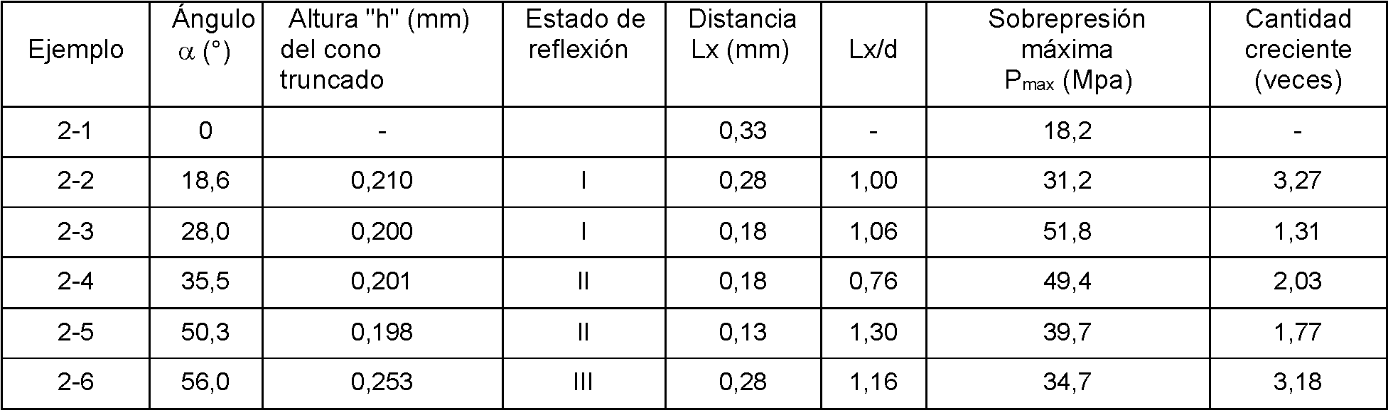
A partir de los resultados antes mencionados, en la Condición (I), cuando Lx/d era 1,00 y 1,06, se presentó la sobrepresión máxima Pmax. Además, cuando 0<Lx/d<1,5, las cantidades crecientes excedieron 1. En particular, cuando 0,5<Lx/d<1,2, la sobrepresión máxima se volvió superior a la sobrepresión del valor de referencia en 10 MPa o más.From the aforementioned results, in Condition (I), when Lx/d was 1.00 and 1.06, the maximum overpressure Pmax occurred. In addition, when 0<Lx/d<1.5, the increasing amounts exceeded 1. In particular, when 0.5<Lx/d<1.2, the maximum overpressure became higher than the reference value overpressure by 10 MPa or more.
En la Condición (II), cuando Lx/d era 0,76 y 1,30, se presentó la sobrepresión máxima Pmax. Además, cuando 0<Lx/d<1,35, las cantidades crecientes excedieron 1. En particular, cuando 0,5<Lx/d<1,25, la sobrepresión máxima se volvió superior a la sobrepresión del valor de referencia en 10 MPa o más. En el ejemplo 2-5 (a=50,3°), incluso cuando Lx/d excedió 2, la cantidad creciente excedió 1. Se considera que esto se debe a que, en el Ejemplo 2-5 (a=50,3°) en comparación con el Ejemplo 2-4 (a=35,5°), la reflexión interna (reflexión total) del rayo láser de pulso en la parte de convergencia del rayo láser 17 se redujo abruptamente, y el efecto del rayo láser de impulsos transmitido a través de la parte de convergencia del rayo láser 17 se hizo más grande.In Condition (II), when Lx/d was 0.76 and 1.30, the maximum overpressure Pmax occurred. In addition, when 0<Lx/d<1.35, the increasing amounts exceeded 1. In particular, when 0.5<Lx/d<1.25, the maximum overpressure became higher than the reference value overpressure by 10 MPa or more. In Example 2-5 (a=50.3°), even when Lx/d exceeded 2, the increasing quantity exceeded 1. This is considered to be because, in Example 2-5 (a=50.3 °) Compared with Example 2-4 (a=35.5°), the internal reflection (total reflection) of the pulsed laser beam at the converging part of the laser beam 17 was abruptly reduced, and the effect of the laser beam of pulses transmitted through the converging part of the laser beam 17 became larger.
En la Condición (III), cuando Lx/d era 1,16, se presentó la sobrepresión máxima Pmax. Además, cuando 0<Lx/d (rango máximo de medición: 2,41), la cantidad creciente excedió 1. En particular, cuando 0,5<Lx/d<1,75, la sobrepresión máxima se volvió superior a la sobrepresión del valor de referencia en 10 MPa o más.In Condition (III), when Lx/d was 1.16, the maximum overpressure Pmax occurred. In addition, when 0<Lx/d (maximum measurement range: 2.41), the increasing quantity exceeded 1. In particular, when 0.5<Lx/d<1.75, the maximum overpressure became higher than the overpressure from the reference value by 10 MPa or more.
En el Ejemplo 2-3 (a=28°) y el Ejemplo 2-4 (a=35,5°), los valores máximos de sobrepresión máxima fueron 51,8 MPa y 49,4 MPa, respectivamente, y se pudo aumentar a alrededor de 50 MPa. Mientras tanto, en el Ejemplo 2-2, incluso con la Condición (I), el valor máximo de la sobrepresión máxima se hizo más pequeño que en el Ejemplo 2-4 con la Condición (II). Se considera que esto se debe a que, en el Ejemplo 2-1, una distancia de propagación en el líquido a una posición enfocada del rayo láser de pulso es larga, y el rayo láser de pulso es absorbido en el líquido antes de alcanzar la posición enfocada.In Example 2-3 (a=28°) and Example 2-4 (a=35.5°), the maximum values of maximum overpressure were 51.8 MPa and 49.4 MPa, respectively, and could be increased at about 50 MPa. Meanwhile, in Example 2-2, even with Condition (I), the maximum value of the maximum overpressure became smaller than in Example 2-4 with Condition (II). This is considered to be because, in Example 2-1, a propagation distance in the liquid to a focused position of the pulsed laser beam is long, and the pulsed laser beam is absorbed in the liquid before reaching the focused position.
[Ejemplos 3-1 a 3-3][Examples 3-1 to 3-3]
Como fibra óptica 11, se prepararon fibras ópticas con un diámetro de núcleo de la parte del cuerpo principal 16 de 300 |jm, 400 |jm y 600 jim, respectivamente, el ángulo a formado por ambos lados del trapezoide isósceles expresado por la sección transversal en el eje la dirección de la parte de convergencia del rayo láser 17 de 26,4° a 29,0° y la altura del cono truncado de la parte de convergencia del rayo láser 17 de 0,17 mm a 0,44 mm.As the optical fiber 11, optical fibers with a core diameter of the main body part 16 of 300 |jm, 400 |jm and 600 jm, respectively, were prepared, the angle a formed by both sides of the isosceles trapezoid expressed by the cross section in the axis the direction of the convergence part of the laser beam 17 from 26.4° to 29.0° and the height of the truncated cone of the convergence part of the laser beam 17 from 0.17 mm to 0.44 mm.
Esa fibra óptica 11 se fijó al reflector que tiene la superficie cóncava que tiene una elipticidad de 1,5, que se obtiene al cortar por un plano perpendicular al eje principal, para formar el dispositivo generador de ondas de choque 10. That optical fiber 11 was attached to the reflector having the concave surface having an ellipticity of 1.5, which is obtained by cutting through a plane perpendicular to the main axis, to form the shock wave generating device 10.
Esos dispositivos generadores de ondas de choque 10 también satisfacen la Condición (I) en la que la parte de convergencia del rayo láser 17 refleja totalmente todo el rayo láser de pulso. Como en los Ejemplos 1-1 a 1-10, la sobrepresión máxima Pmax de la onda de choque generada al cambiar la posición del extremo distal de la fibra óptica 11 se midió con el uso de un sensor de presión, y se examinó la distancia Lx a la que se maximizaba la sobrepresión máxima Pmax de la onda de choque. Los resultados de la medición se muestran en la Tabla 3 y la Figura 10 y la Figura 11 (a) a la Figura 11 (c).Those shock wave generating devices 10 also satisfy Condition (I) in which the converging part of the laser beam 17 fully reflects the entire pulse laser beam. As in Examples 1-1 to 1-10, the maximum overpressure Pmax of the shock wave generated by changing the position of the distal end of the optical fiber 11 was measured with the use of a pressure sensor, and the distance was examined. Lx at which the maximum overpressure Pmax of the shock wave was maximized. The measurement results are shown in Table 3 and Figure 10 and Figure 11(a) to Figure 11(c).
A partir de esos resultados, se descubrió que, cuando el ángulo a estaba cercano a los 30°, se establecía una relación de la [Ecuación 1] y [Ecuación 2] entre una distancia X desde el extremo distal de la fibra óptica hasta el centro de la onda de choque, y el diámetro del núcleo M.From these results, it was found that, when the angle a was close to 30°, a relationship of [Equation 1] and [Equation 2] was established between a distance X from the distal end of the optical fiber to the center of the shock wave, and the core diameter M.
Tabla 3]Table 3]

[Ejemplo 4-1, Ejemplo 4-2 y Ejemplo comparativo 4-1].[Example 4-1, Example 4-2 and Comparative Example 4-1].
Finalmente, mediante el Ejemplo 4-1, el Ejemplo 4-2 y el Ejemplo comparativo 4-1, se examinó la relación entre la forma de la superficie cóncava 21 y la sobrepresión máxima Pmax.Finally, by means of Example 4-1, Example 4-2 and Comparative Example 4-1, the relationship between the shape of the concave surface 21 and the maximum overpressure Pmax was examined.
1. Diseño del reflector1. Reflector design
Como fibra óptica 11, se preparó una fibra óptica hecha de cuarzo deshidroxilado, que tiene el diámetro del núcleo de la parte del cuerpo principal de 400 μm, el índice de refracción nqtz de 1,437, el ángulo a de la parte de convergencia del rayo láser 17 de 30° y la una altura "h" del cono truncado de 0,23 mm. Esta fibra óptica 11 se inserta en un reflector 20 que es similar a la de los Ejemplos 1-1 a 1-10, y se ajusta para que la distancia Lx sea de 0,23 mm para formar el dispositivo generador de ondas de choque 10. Este dispositivo generador de ondas de choque 10 también satisface la Condición (I) en la que la parte de convergencia del rayo láser 17 refleja totalmente todo el rayo láser de pulso.As the optical fiber 11, an optical fiber made of dehydroxylated quartz was prepared, having the core diameter of the main body part of 400 µm, the refractive index nqtz of 1.437, the angle a of the convergence part of the laser beam 17 of 30° and a height "h" of the truncated cone of 0.23 mm. This optical fiber 11 is inserted into a reflector 20 that is similar to that of Examples 1-1 to 1-10, and is adjusted so that the distance Lx is 0.23 mm to form the shock wave generating device 10. This shock wave generating device 10 also satisfies Condition (I) in which the converging part of the laser beam 17 fully reflects the entire pulse laser beam.
(1) Paso 1(1) Step 1
El dispositivo generador de ondas de choque 10 se utilizó para irradiar el líquido 24 con el rayo láser de pulso (longitud de onda: 2,1 μm, ancho de pulso: 100 nseg, 43 mJ/pulso a 48 mJ/pulso, período de oscilación: 1 Hz) para generar la onda de choque y fotografiar el frente de onda S con una cámara de alta velocidad (velocidad de fotografía: 10 Mfps, tiempo de exposición: 50 nseg).The shock wave generating device 10 was used to irradiate the liquid 24 with the pulsed laser beam (wavelength: 2.1 µm, pulse width: 100 nsec, 43 mJ/pulse to 48 mJ/pulse, period of oscillation: 1 Hz) to generate the shock wave and photograph the S-wavefront with a high-speed camera (photography speed: 10 Mfps, exposure time: 50 nsec).
(2) Pasos 2 a 4(2) Steps 2 to 4
A partir de la imagen de alta velocidad obtenida de este modo, se identificó el punto de intersección Sf del frente de onda S de la onda de choque y la línea extendida del eje central de la fibra óptica 11. A partir de los resultados de la Tabla 2, se supuso que la posición a 230 μm frente al extremo distal de la parte de convergencia del rayo láser 17 era el punto central C de la onda de choque, y un círculo (círculo completo) que tenía el punto central C como el centro y pasó por el punto de intersección Sf se definió como el frente de onda I de la onda de choque ideal.From the high-speed image thus obtained, the intersection point Sf of the wavefront S of the shock wave and the extended line of the central axis of the optical fiber 11 was identified. From the results of the Table 2, the position at 230 µm in front of the distal end of the convergence part of the laser beam 17 was assumed to be the center point C of the shock wave, and a circle (full circle) having the center point C as the center and passed through the point of intersection Sf was defined as the wavefront I of the ideal shock wave.
(3) Paso 5(3) Step 5
Se determinaron el ángulo (ángulo central) 0 alrededor del punto central C con respecto a la línea recta que conecta el punto de intersección Sf y el punto central C y la distancia AD entre el punto S0 en el frente de onda S de la onda de choque y el punto I0 en el frente de onda I de la onda de choque ideal. Los resultados de la determinación se muestran en la Figura 12.The angle (central angle) 0 around the central point C with respect to the straight line connecting the intersection point Sf and the central point C and the distance AD between the point S0 on the S wave front of the wave shock and the point I0 on the wavefront I of the ideal shock wave. The results of the determination are shown in Figure 12.
(4) Paso 6(4) Step 6
La forma elipsoidal (x, y) expresada por la expresión de la [Ecuación 21] (caso en que a/b=1,5 y b=1,8 en la expresión de la [Ecuación 5]) se modificó, después de superponer entre sí el punto focal F (de los puntos focales del esferoide cortado descritos anteriormente, el punto focal correspondiente al punto focal situado en el interior de la parte reflectante 12) de la forma elipsoidal y el punto central C de la onda de choque ideal, a la forma (x1, y1) que satisface la expresión de la [Ecuación 6] basándose en la relación de la Figura 12 determinada en el Paso 5.The ellipsoidal shape (x, y) expressed by the expression of [Equation 21] (case in which a/b=1.5 and b=1.8 in the expression of [Equation 5]) was modified, after superimposing the focal point F (of the focal points of the cut spheroid described above, the focal point corresponding to the focal point located inside the reflecting part 12) of the ellipsoidal shape and the center point C of the ideal shock wave, with each other, to the form (x 1 , y 1 ) that satisfies the expression in [Equation 6] based on the relationship in Figure 12 determined in Step 5.

(5) Paso 7(5) Step 7
La forma así modificada se hizo girar con un eje principal de una elipse expresada por la expresión de la [Ecuación 21] siendo un eje de rotación para determinar la forma de la superficie cóncava 21 del reflector 20. El reflector 20 fue diseñado en base a la forma de la superficie cóncava 21.The thus modified shape was rotated with a principal axis of an ellipse expressed by the expression of [Equation 21] being an axis of rotation to determine the shape of the concave surface 21 of the reflector 20. The reflector 20 was designed based on the shape of the concave surface 21.
2. Medida de sobrepresión máxima Pmax de onda de choque2. Measurement of maximum overpressure Pmax of shock wave
Como fibra óptica 11, se preparó una fibra óptica hecha de cuarzo deshidroxilado, que tenía el diámetro del núcleo de la parte del cuerpo principal de 400 μm, el índice de refracción nqtz de 1,437, el ángulo a de la parte de convergencia del rayo láser 17 de 30° y la una altura "h" del cono truncado de 0,23 mm. La fibra óptica 11 se unió al reflector 20 en cada uno de los Ejemplos 4-1 y 4-2 y el Ejemplo comparativo 4-1 para formar el dispositivo generador de ondas de choque 10. Luego, se generó realmente la onda de choque, y se midió la sobrepresión máxima Pmax de la onda de choque reflejada y convergida en un punto fuera de la parte reflectante 12 para examinar la relación entre la forma de la superficie cóncava 21 y la sobrepresión máxima Pmax de la onda de choque.As the optical fiber 11, an optical fiber made of dehydroxylated quartz was prepared, having the core diameter of the main body part of 400 µm, the refractive index nqtz of 1.437, the angle a of the convergence part of the laser beam 17 of 30° and a height "h" of the truncated cone of 0.23 mm. The optical fiber 11 was attached to the reflector 20 in each of Examples 4-1 and 4-2 and Comparative Example 4-1 to form the shock wave generating device 10. Then, the shock wave was actually generated, and the maximum overpressure Pmax of the reflected and converged shock wave at a point outside the reflective part 12 was measured to examine the relationship between the shape of the concave surface 21 and the maximum overpressure Pmax of the shock wave.
(Ejemplo 4-1)(Example 4-1)
Al reflector 20 diseñado como se describe anteriormente, se unió la fibra óptica 11 de manera que la distancia Lx se ajustó a 0,23 mm para formar el dispositivo generador de ondas de choque 10.To the reflector 20 designed as described above, the optical fiber 11 was attached so that the distance Lx was set to 0.23 mm to form the shock wave generating device 10.
El dispositivo generador de ondas de choque 10 se utilizó para generar la onda de choque y medir la sobrepresión máxima Pmax de la onda de choque reflejada y convergida en un punto fuera de la parte reflectante 12 con el uso de un sensor de presión. En ese momento, el rayo láser de pulso irradiado para generar la onda de choque tenía una longitud de onda de 2,1 μm, un ancho de pulso de 100 nseg, 43 mJ/pulso a 48 mJ/pulso y un período de oscilación de 1 Hz.The shock wave generating device 10 was used to generate the shock wave and measure the maximum overpressure Pmax of the reflected and converged shock wave at a point outside the reflecting part 12 with the use of a pressure sensor. At that time, the pulsed laser beam irradiated to generate the shock wave had a wavelength of 2.1 μm, a pulse width of 100 nsec, 43 mJ/pulse to 48 mJ/pulse, and an oscillation period of 1hz.
(Ejemplo 4-2)(Example 4-2)
De manera similar al Ejemplo 4-1, salvo que se utilizó como reflector 20 un reflector que tenía la superficie cóncava 21 obtenida cortando la forma esferoidal que tenía la elipticidad a/b de 1,5 por un plano perpendicular al eje principal, se midió la sobrepresión máxima Pmax de la onda de choque.In a similar manner to Example 4-1, except that a reflector having the concave surface 21 obtained by cutting the spheroidal shape having the ellipticity a/b of 1.5 was used as the reflector 20 by a plane perpendicular to the principal axis, it was measured the maximum overpressure Pmax of the shock wave.
(Ejemplo comparativo 4-1)(Comparative Example 4-1)
De manera similar al Ejemplo 4-1, salvo que se utilizó como reflector 20 un reflector que tenía la superficie cóncava 21 obtenida cortando la forma esferoidal que tenía la elipticidad a/b de 1,5 por un plano perpendicular al eje principal, y que la distancia Lx se ajustó para que fuera de 0 mm (el extremo distal de la fibra óptica 11 se ajustó para que coincidiera con el punto focal F de la superficie cóncava 21), se midió la sobrepresión máxima Pmax de la onda de choque. Los resultados de las mediciones se muestran en la Tabla 4 y la Figura 13.In a similar manner to Example 4-1, except that a reflector having the concave surface 21 obtained by cutting the spheroidal shape having the ellipticity a/b of 1.5 was used as the reflector 20 by a plane perpendicular to the principal axis, and having the distance Lx was set to be 0 mm (the distal end of the optical fiber 11 was set to coincide with the focal point F of the concave surface 21), the maximum overpressure Pmax of the shock wave was measured. The results of the measurements are shown in Table 4 and Figure 13.
[Tabla 4][Table 4]

Ejemplo 4-1 y el Ejemplo 4-2, en comparación con el dispositivo generador de ondas de choque según el Ejemplo comparativo 4-1, la sobrepresión máxima Pmax de la onda de choque reflejada y convergente era alta. También se confirmó que, con el dispositivo generador de ondas de choque según el Ejemplo 4-1, la sobrepresión máxima Pmax de la onda de choque se incrementó hasta aproximadamente 1,35 veces la sobrepresión máxima Pmax obtenida con el dispositivo generador de ondas de choque según el Ejemplo 4-2.Example 4-1 and Example 4-2, in comparison with the shock wave generating device according to Comparative Example 4-1, the maximum overpressure Pmax of the reflected and converging shock wave was high. It was also confirmed that, with the shock wave generating device according to Example 4-1, the maximum overpressure Pmax of the shock wave was increased to about 1.35 times of the maximum overpressure Pmax obtained with the shock wave generating device. according to Example 4-2.
Explicación de los números de referenciaExplanation of reference numbers
10: dispositivo generador de ondas de choque, 11: fibra óptica, 12: parte reflectante, 14: catéter, 16: parte del cuerpo principal, 16a: núcleo, 16b: revestimiento, 17: parte de convergencia del rayo láser, 17a: superficie del extremo distal, 17b: ambos lados, 20: reflector, 21: superficie cóncava, 22: orificio pasante, 22a: parte frontal del orificio pasante, 23: cuerpo de sellado, 24: líquido, 31: parte de conexión de la tubería de suministro de agua, 32: parte de conexión de la tubería de descarga de agua, 33: elemento de fijación 10: shock wave generating device, 11: optical fiber, 12: reflective part, 14: catheter, 16: main body part, 16a: core, 16b: cladding, 17: laser beam convergence part, 17a: surface of the distal end, 17b: both sides, 20: reflector, 21: concave surface, 22: through hole, 22a: front part of the through hole, 23: sealing body, 24: liquid, 31: connection part of the tube of water supply, 32: connection part of water discharge pipe, 33: fixing element
Claims (6)


Applications Claiming Priority (2)
| Application Number | Priority Date | Filing Date | Title |
|---|---|---|---|
| JP2018066022 | 2018-03-29 | ||
| PCT/JP2019/013827 WO2019189672A1 (en) | 2018-03-29 | 2019-03-28 | Shock wave generating device, and shock wave ablation system |
Publications (1)
| Publication Number | Publication Date |
|---|---|
| ES2945219T3 true ES2945219T3 (en) | 2023-06-29 |
Family
ID=68059091
Family Applications (1)
| Application Number | Title | Priority Date | Filing Date |
|---|---|---|---|
| ES19776260T Active ES2945219T3 (en) | 2018-03-29 | 2019-03-28 | Shock wave generating device and shock wave ablation system |
Country Status (6)
| Country | Link |
|---|---|
| US (1) | US11364079B2 (en) |
| EP (1) | EP3777747B1 (en) |
| JP (1) | JP7269662B2 (en) |
| CN (1) | CN112153947B (en) |
| ES (1) | ES2945219T3 (en) |
| WO (1) | WO2019189672A1 (en) |
Families Citing this family (3)
| Publication number | Priority date | Publication date | Assignee | Title |
|---|---|---|---|---|
| WO2023285994A1 (en) * | 2021-07-16 | 2023-01-19 | Arthrex, Inc. | Surgical electrode assembly with focal point projection |
| CN114323392B (en) * | 2022-03-11 | 2022-05-13 | 中国工程物理研究院流体物理研究所 | Probe, probe assembly, measuring device and measuring method for detonation testing |
| CN120814900B (en) * | 2025-09-16 | 2025-12-02 | 湖南省华芯医疗器械有限公司 | Operation early warning method and device based on image recognition and endoscope |
Family Cites Families (8)
| Publication number | Priority date | Publication date | Assignee | Title |
|---|---|---|---|---|
| JPS5435739B2 (en) | 1974-02-28 | 1979-11-05 | ||
| DE3506249A1 (en) * | 1985-02-22 | 1986-08-28 | Messerschmitt-Bölkow-Blohm GmbH, 8012 Ottobrunn | METHOD AND DEVICE FOR SMASHING A SOLID BODY |
| DE4440783C2 (en) * | 1993-11-15 | 2000-06-29 | Storz Endoskop Gmbh Schaffhaus | Device for cutting tissue |
| JP2004215862A (en) * | 2003-01-15 | 2004-08-05 | Tohoku Techno Arch Co Ltd | Shock wave generator |
| ES2366103T3 (en) * | 2005-05-12 | 2011-10-17 | Koninklijke Philips Electronics N.V. | DEVICE FOR THE CONTROL OF HAIR GROWTH. |
| JP4635233B2 (en) * | 2007-09-06 | 2011-02-23 | 株式会社ハイレックスコーポレーション | Shock wave ablation system |
| JP5435739B2 (en) * | 2010-10-19 | 2014-03-05 | 国立大学法人東北大学 | Optical fiber and underwater shock wave generator using the same |
| EP2939630B1 (en) * | 2012-12-26 | 2018-02-14 | Tohoku University | Shock wave focusing device, shock wave generation apparatus, and shock wave ablation system |
-
2019
- 2019-03-28 ES ES19776260T patent/ES2945219T3/en active Active
- 2019-03-28 CN CN201980033726.6A patent/CN112153947B/en active Active
- 2019-03-28 WO PCT/JP2019/013827 patent/WO2019189672A1/en not_active Ceased
- 2019-03-28 US US17/043,040 patent/US11364079B2/en active Active
- 2019-03-28 EP EP19776260.2A patent/EP3777747B1/en active Active
- 2019-03-28 JP JP2020511041A patent/JP7269662B2/en active Active
Also Published As
| Publication number | Publication date |
|---|---|
| US11364079B2 (en) | 2022-06-21 |
| WO2019189672A1 (en) | 2019-10-03 |
| JPWO2019189672A1 (en) | 2021-04-01 |
| EP3777747A4 (en) | 2022-01-05 |
| CN112153947A (en) | 2020-12-29 |
| JP7269662B2 (en) | 2023-05-09 |
| CN112153947B (en) | 2024-08-20 |
| US20210100615A1 (en) | 2021-04-08 |
| EP3777747B1 (en) | 2023-03-15 |
| EP3777747A1 (en) | 2021-02-17 |
Similar Documents
| Publication | Publication Date | Title |
|---|---|---|
| US9433466B2 (en) | Optical fiber and an underwater shockwave generating device employing the same | |
| US20190000549A1 (en) | Radial Emissions from Optical Fibers | |
| ES2387697T3 (en) | Thermally robust lighting probe | |
| EP3597133B1 (en) | Side-fire laser fiber having a molded reflective surface | |
| ES2391579T3 (en) | Fiber optic connector | |
| JP2019164331A5 (en) | ||
| WO2009001266A2 (en) | Acoustic offset for transducer | |
| US11998269B2 (en) | Forming radial emissions from optical fibers | |
| ES2885175T3 (en) | Light diffusion devices for use in photoimmunotherapy | |
| CN106058619A (en) | Laser light irradiation apparatus and laser peening treatment method | |
| CN112153947B (en) | Shock wave generating device and shock wave ablation system | |
| KR101985091B1 (en) | Laser processing device | |
| JP2022503332A (en) | Body tissue treatment device and method for manufacturing the device | |
| JPWO2019189672A5 (en) | ||
| KR101144720B1 (en) | Optical Fiber with Reflective Grooves | |
| US7780655B2 (en) | Medical or cosmetic hand-held laser device | |
| HK40039288A (en) | Shock wave generating device, and shock wave ablation system | |
| ES2891304T3 (en) | Intraocular lens with a single-lens telescope integrated into the optics | |
| CN118453108A (en) | Laser therapeutic head and laser therapeutic apparatus | |
| WO2024062902A1 (en) | Light radiating fiber probe | |
| JP7773481B2 (en) | Light irradiation medical device | |
| RU2528655C1 (en) | Fibre-optic tool with curved distal working part | |
| CN113455995A (en) | Varifocal three-dimensional scanning endoscopic probe | |
| EP3648696A1 (en) | Optical fibers and associated systems | |
| HK40039288B (en) | Shock wave generating device, and shock wave ablation system |