ES2950908T3 - Actively damped centerless grinding process - Google Patents
Actively damped centerless grinding process Download PDFInfo
- Publication number
- ES2950908T3 ES2950908T3 ES18382825T ES18382825T ES2950908T3 ES 2950908 T3 ES2950908 T3 ES 2950908T3 ES 18382825 T ES18382825 T ES 18382825T ES 18382825 T ES18382825 T ES 18382825T ES 2950908 T3 ES2950908 T3 ES 2950908T3
- Authority
- ES
- Spain
- Prior art keywords
- grinding
- vibrations
- machine
- grinding process
- damping force
- Prior art date
- Legal status (The legal status is an assumption and is not a legal conclusion. Google has not performed a legal analysis and makes no representation as to the accuracy of the status listed.)
- Active
Links
Classifications
-
- B—PERFORMING OPERATIONS; TRANSPORTING
- B24—GRINDING; POLISHING
- B24B—MACHINES, DEVICES, OR PROCESSES FOR GRINDING OR POLISHING; DRESSING OR CONDITIONING OF ABRADING SURFACES; FEEDING OF GRINDING, POLISHING, OR LAPPING AGENTS
- B24B5/00—Machines or devices designed for grinding surfaces of revolution on work, including those which also grind adjacent plane surfaces; Accessories therefor
- B24B5/18—Machines or devices designed for grinding surfaces of revolution on work, including those which also grind adjacent plane surfaces; Accessories therefor involving centreless means for supporting, guiding, floating or rotating work
-
- B—PERFORMING OPERATIONS; TRANSPORTING
- B24—GRINDING; POLISHING
- B24B—MACHINES, DEVICES, OR PROCESSES FOR GRINDING OR POLISHING; DRESSING OR CONDITIONING OF ABRADING SURFACES; FEEDING OF GRINDING, POLISHING, OR LAPPING AGENTS
- B24B41/00—Component parts such as frames, beds, carriages, headstocks
- B24B41/007—Weight compensation; Temperature compensation; Vibration damping
-
- B—PERFORMING OPERATIONS; TRANSPORTING
- B23—MACHINE TOOLS; METAL-WORKING NOT OTHERWISE PROVIDED FOR
- B23Q—DETAILS, COMPONENTS, OR ACCESSORIES FOR MACHINE TOOLS, e.g. ARRANGEMENTS FOR COPYING OR CONTROLLING; MACHINE TOOLS IN GENERAL CHARACTERISED BY THE CONSTRUCTION OF PARTICULAR DETAILS OR COMPONENTS; COMBINATIONS OR ASSOCIATIONS OF METAL-WORKING MACHINES, NOT DIRECTED TO A PARTICULAR RESULT
- B23Q1/00—Members which are comprised in the general build-up of a form of machine, particularly relatively large fixed members
- B23Q1/25—Movable or adjustable work or tool supports
- B23Q1/44—Movable or adjustable work or tool supports using particular mechanisms
- B23Q1/56—Movable or adjustable work or tool supports using particular mechanisms with sliding pairs only, the sliding pairs being the first two elements of the mechanism
- B23Q1/60—Movable or adjustable work or tool supports using particular mechanisms with sliding pairs only, the sliding pairs being the first two elements of the mechanism two sliding pairs only, the sliding pairs being the first two elements of the mechanism
-
- B—PERFORMING OPERATIONS; TRANSPORTING
- B23—MACHINE TOOLS; METAL-WORKING NOT OTHERWISE PROVIDED FOR
- B23Q—DETAILS, COMPONENTS, OR ACCESSORIES FOR MACHINE TOOLS, e.g. ARRANGEMENTS FOR COPYING OR CONTROLLING; MACHINE TOOLS IN GENERAL CHARACTERISED BY THE CONSTRUCTION OF PARTICULAR DETAILS OR COMPONENTS; COMBINATIONS OR ASSOCIATIONS OF METAL-WORKING MACHINES, NOT DIRECTED TO A PARTICULAR RESULT
- B23Q11/00—Accessories fitted to machine tools for keeping tools or parts of the machine in good working condition or for cooling work; Safety devices specially combined with or arranged in, or specially adapted for use in connection with, machine tools
- B23Q11/0032—Arrangements for preventing or isolating vibrations in parts of the machine
-
- B—PERFORMING OPERATIONS; TRANSPORTING
- B24—GRINDING; POLISHING
- B24B—MACHINES, DEVICES, OR PROCESSES FOR GRINDING OR POLISHING; DRESSING OR CONDITIONING OF ABRADING SURFACES; FEEDING OF GRINDING, POLISHING, OR LAPPING AGENTS
- B24B41/00—Component parts such as frames, beds, carriages, headstocks
- B24B41/02—Frames; Beds; Carriages
-
- B—PERFORMING OPERATIONS; TRANSPORTING
- B24—GRINDING; POLISHING
- B24B—MACHINES, DEVICES, OR PROCESSES FOR GRINDING OR POLISHING; DRESSING OR CONDITIONING OF ABRADING SURFACES; FEEDING OF GRINDING, POLISHING, OR LAPPING AGENTS
- B24B49/00—Measuring or gauging equipment for controlling the feed movement of the grinding tool or work; Arrangements of indicating or measuring equipment, e.g. for indicating the start of the grinding operation
-
- B—PERFORMING OPERATIONS; TRANSPORTING
- B24—GRINDING; POLISHING
- B24B—MACHINES, DEVICES, OR PROCESSES FOR GRINDING OR POLISHING; DRESSING OR CONDITIONING OF ABRADING SURFACES; FEEDING OF GRINDING, POLISHING, OR LAPPING AGENTS
- B24B5/00—Machines or devices designed for grinding surfaces of revolution on work, including those which also grind adjacent plane surfaces; Accessories therefor
- B24B5/18—Machines or devices designed for grinding surfaces of revolution on work, including those which also grind adjacent plane surfaces; Accessories therefor involving centreless means for supporting, guiding, floating or rotating work
- B24B5/22—Machines or devices designed for grinding surfaces of revolution on work, including those which also grind adjacent plane surfaces; Accessories therefor involving centreless means for supporting, guiding, floating or rotating work for grinding cylindrical surfaces, e.g. on bolts
-
- G—PHYSICS
- G05—CONTROLLING; REGULATING
- G05B—CONTROL OR REGULATING SYSTEMS IN GENERAL; FUNCTIONAL ELEMENTS OF SUCH SYSTEMS; MONITORING OR TESTING ARRANGEMENTS FOR SUCH SYSTEMS OR ELEMENTS
- G05B19/00—Program-control systems
- G05B19/02—Program-control systems electric
- G05B19/18—Numerical control [NC], i.e. automatically operating machines, in particular machine tools, e.g. in a manufacturing environment, so as to execute positioning, movement or co-ordinated operations by means of program data in numerical form
- G05B19/404—Numerical control [NC], i.e. automatically operating machines, in particular machine tools, e.g. in a manufacturing environment, so as to execute positioning, movement or co-ordinated operations by means of program data in numerical form characterised by control arrangements for compensation, e.g. for backlash, overshoot, tool offset, tool wear, temperature, machine construction errors, load, inertia
-
- B—PERFORMING OPERATIONS; TRANSPORTING
- B23—MACHINE TOOLS; METAL-WORKING NOT OTHERWISE PROVIDED FOR
- B23Q—DETAILS, COMPONENTS, OR ACCESSORIES FOR MACHINE TOOLS, e.g. ARRANGEMENTS FOR COPYING OR CONTROLLING; MACHINE TOOLS IN GENERAL CHARACTERISED BY THE CONSTRUCTION OF PARTICULAR DETAILS OR COMPONENTS; COMBINATIONS OR ASSOCIATIONS OF METAL-WORKING MACHINES, NOT DIRECTED TO A PARTICULAR RESULT
- B23Q15/00—Automatic control or regulation of feed movement, cutting velocity or position of tool or work
- B23Q15/007—Automatic control or regulation of feed movement, cutting velocity or position of tool or work while the tool acts upon the workpiece
- B23Q15/12—Adaptive control, i.e. adjusting itself to have a performance which is optimum according to a preassigned criterion
-
- G—PHYSICS
- G05—CONTROLLING; REGULATING
- G05B—CONTROL OR REGULATING SYSTEMS IN GENERAL; FUNCTIONAL ELEMENTS OF SUCH SYSTEMS; MONITORING OR TESTING ARRANGEMENTS FOR SUCH SYSTEMS OR ELEMENTS
- G05B2219/00—Program-control systems
- G05B2219/30—Nc systems
- G05B2219/37—Measurements
- G05B2219/37434—Measuring vibration of machine or workpiece or tool
-
- G—PHYSICS
- G05—CONTROLLING; REGULATING
- G05B—CONTROL OR REGULATING SYSTEMS IN GENERAL; FUNCTIONAL ELEMENTS OF SUCH SYSTEMS; MONITORING OR TESTING ARRANGEMENTS FOR SUCH SYSTEMS OR ELEMENTS
- G05B2219/00—Program-control systems
- G05B2219/30—Nc systems
- G05B2219/41—Servomotor, servo controller till figures
- G05B2219/41256—Chattering control
-
- G—PHYSICS
- G05—CONTROLLING; REGULATING
- G05B—CONTROL OR REGULATING SYSTEMS IN GENERAL; FUNCTIONAL ELEMENTS OF SUCH SYSTEMS; MONITORING OR TESTING ARRANGEMENTS FOR SUCH SYSTEMS OR ELEMENTS
- G05B2219/00—Program-control systems
- G05B2219/30—Nc systems
- G05B2219/45—Nc applications
- G05B2219/45145—Milling
Landscapes
- Engineering & Computer Science (AREA)
- Mechanical Engineering (AREA)
- Automation & Control Theory (AREA)
- Manufacturing & Machinery (AREA)
- Physics & Mathematics (AREA)
- General Physics & Mathematics (AREA)
- Human Computer Interaction (AREA)
- Constituent Portions Of Griding Lathes, Driving, Sensing And Control (AREA)
- Grinding Of Cylindrical And Plane Surfaces (AREA)
- Vibration Prevention Devices (AREA)
- Crushing And Grinding (AREA)
- Transition And Organic Metals Composition Catalysts For Addition Polymerization (AREA)
- Polishing Bodies And Polishing Tools (AREA)
Abstract
La presente invención se refiere a un proceso de rectificado sin centros con amortiguación activa para una máquina rectificadora sin centros que tiene ruedas (1, 2), entre las cuales está dispuesta una pieza (3) a rectificar, y cabezales (5, 6) que transportan las ruedas (1). , 2), proceso que comprende acercar las muelas (1, 2) entre sí aplicando presión sobre la pieza (3) para su rectificado, de manera que se generan vibraciones en la rectificadora debido al rectificado, midiendo las vibraciones debidas al rectificado. al rectificado, e introduciendo, en función de dicha medida, una fuerza amortiguadora activa (Fact) paralela al flujo de fuerzas de la rectificadora y mediante el uso de un actuador inercial (10) que actúa directamente sobre uno de los cabezales (5, 6) , de manera que se atenúen las vibraciones debidas al rectificado. (Traducción automática con Google Translate, sin valor legal)The present invention relates to a centerless grinding process with active damping for a centerless grinding machine having wheels (1, 2), between which a part (3) to be ground is arranged, and heads (5, 6). carried by the wheels (1). , 2), a process that includes bringing the wheels (1, 2) closer to each other by applying pressure on the piece (3) for grinding, so that vibrations are generated in the grinding machine due to grinding, measuring the vibrations due to grinding. to the grinding, and introducing, based on said measurement, an active damping force (Fact) parallel to the flow of forces of the grinding machine and through the use of an inertial actuator (10) that acts directly on one of the heads (5, 6 ), so that vibrations due to grinding are attenuated. (Automatic translation with Google Translate, without legal value)
Description
DESCRIPCIÓNDESCRIPTION
Proceso de rectificado sin centros activamente amortiguadoActively damped centerless grinding process
Sector de la técnicaTechnical sector
La presente invención se refiere a un proceso para llevar a cabo el rectificado de una pieza en una máquina rectificadora sin centro. El proceso propuesto emplea una estrategia de control que, mediante un actuador inercial, permite introducir una fuerza de amortiguamiento activo que atenúa las vibraciones que se producen debido al propio proceso de rectificado, mejorando así la precisión de la máquina rectificadora sin centro.The present invention relates to a process for grinding a part on a centerless grinding machine. The proposed process uses a control strategy that, through an inertial actuator, allows the introduction of an active damping force that attenuates the vibrations that occur due to the grinding process itself, thus improving the precision of the centerless grinding machine.
Estado de la técnicaState of the art
El rectificado es un proceso muy empleado para realizar mecanizados por abrasión, con mayor precisión dimensional y menores rugosidades que el mecanizado por arranque de viruta. Es por ello que, principalmente, el rectificado es tratado como un proceso de acabado, en donde las fuerzas del proceso de rectificado no son muy grandes.Grinding is a process widely used to perform abrasion machining, with greater dimensional precision and lower roughness than chip removal machining. This is why grinding is mainly treated as a finishing process, where the forces of the grinding process are not very great.
Así, el rectificado general se centra esencialmente en mejorar la precisión y, por ello, las técnicas empleadas actualmente se centran en eliminar vibraciones de tipo constante de la máquina. Por ejemplo, con el objetivo de mejorar la precisión de la máquina rectificadora existen los documentos JP2005199410A, o JP2002254303A, los cuales proponen técnicas de cancelación de las vibraciones debidas al desequilibrio de la rueda.Thus, general grinding essentially focuses on improving precision and, therefore, the techniques currently used focus on eliminating constant machine vibrations. For example, with the aim of improving the precision of the grinding machine, there are documents JP2005199410A, or JP2002254303A, which propose techniques to cancel vibrations due to wheel imbalance.
Sin embargo, en el rectificado sin centro, que es una variante del rectificado general, estas vibraciones de tipo constante de la máquina quedan en un segundo plano de importancia, ya que el rectificado sin centro se emplea para operaciones de desbaste, y no solo operaciones de acabado. Por ello, en el rectificado sin centro, las vibraciones generadas debido al propio proceso de rectificado, como es el caso de las vibraciones autoexcitadas (retemblado o "chatte?'), son especialmente relevantes.However, in centerless grinding, which is a variant of general grinding, these constant vibrations of the machine take a backseat of importance, since centerless grinding is used for roughing operations, and not only grinding operations. Finishing. Therefore, in centerless grinding, the vibrations generated due to the grinding process itself, such as self-excited vibrations (rattling or 'chatte?'), are especially relevant.
En el rectificado sin centro, la pieza queda colocada en la máquina, sin que haya nada que la sujete mientras es procesada. Este proceso es ampliamente empleado para producir piezas cilindricas de precisión con altos ratios de productividad. Esto se consigue principalmente por eliminar las operaciones de centrado y amarre de la pieza a rectificar, lo cual conlleva una reducción considerable de los tiempos de operación y la posibilidad de automatizar el proceso de rectificado. El hecho de la no necesidad de amarre hace que el rectificado sin centro sea un proceso muy interesante también para mecanizar piezas cilindricas de pequeñas dimensiones comenzando por sus operaciones de desbaste.In centerless grinding, the part is placed in the machine, with nothing to hold it while it is processed. This process is widely used to produce precision cylindrical parts with high productivity ratios. This is achieved mainly by eliminating the centering and clamping operations of the piece to be ground, which leads to a considerable reduction in operating times and the possibility of automating the grinding process. The fact that there is no need for clamping makes centerless grinding a very interesting process also for machining small cylindrical parts starting with their roughing operations.
Además, en el rectificado sin centro, el ancho de rueda empleado suele ser considerablemente mayor en comparación a los procesos de rectificado general, lo que hace que las fuerzas del proceso de rectificado aumenten en consideración. Todo ello hace que, como se ha indicado anteriormente, la precisión en las rectificadoras sin centro dependa principalmente de las vibraciones generadas debido al propio proceso de rectificado, especialmente el "chatte?', quedando en un segundo plano las vibraciones propias de la máquina, como es el caso de la vibración debida al desequilibrio de rueda. Estas vibraciones de proceso dependen principalmente de la rigidez dinámica de la máquina y de las condiciones de rectificado.Furthermore, in centerless grinding, the wheel width used is usually considerably larger compared to general grinding processes, which causes the forces of the grinding process to increase considerably. All this means that, as indicated above, the precision in centerless grinding machines depends mainly on the vibrations generated due to the grinding process itself, especially the "chatte?", leaving the machine's own vibrations in the background, as is the case of vibration due to wheel imbalance.These process vibrations depend mainly on the dynamic rigidity of the machine and the grinding conditions.
Una de las soluciones más efectivas para eliminar las vibraciones ocurridas debido al proceso es la de incrementar el amortiguamiento actuando directamente en el comportamiento dinámico de la máquina rectificadora sin la necesidad de conocer los datos específicos de las condiciones del proceso. Una forma de introducir amortiguamiento, es de manera pasiva, empleando un actuador pasivo que tiene una masa suspendida que puede oscilar libremente según la vibración de la máquina. En el caso de que la resonancia de la masa suspendida coincida con la resonancia de la máquina, esta puede atenuar la vibración. La desventaja de ello es que la masa suspendida debe de tener un valor cuantificable respecto a la masa modal de la vibración y por tanto se requiere un actuador voluminoso que ocuparía gran espacio en máquina. Además, el actuador pasivo solo valdría para un modo de vibración concreto y no se podría adaptar a otros diferentes modos de vibración que pudieran aparecer, lo cual hace que no sea una solución adecuada para amortiguar vibraciones de proceso en una máquina rectificadora sin centro, ya que en este tipo de máquinas las frecuencias de vibración pueden variar según las condiciones de corte.One of the most effective solutions to eliminate the vibrations that occur due to the process is to increase the damping by acting directly on the dynamic behavior of the grinding machine without the need to know the specific data of the process conditions. One way to introduce damping is passively, using a passive actuator that has a suspended mass that can oscillate freely depending on the vibration of the machine. If the resonance of the suspended mass coincides with the resonance of the machine, it can attenuate the vibration. The disadvantage of this is that the suspended mass must have a quantifiable value with respect to the modal mass of the vibration and therefore a bulky actuator is required that would take up a lot of machine space. Furthermore, the passive actuator would only be valid for a specific vibration mode and could not be adapted to other different vibration modes that could appear, which makes it not a suitable solution to dampen process vibrations in a centerless grinding machine, since That in this type of machines the vibration frequencies can vary depending on the cutting conditions.
Los sistemas de amortiguamiento activo pueden suponer una solución para adaptarse a diferentes modos de vibración y atenuar las vibraciones provenientes del proceso de rectificado sin la necesidad de un espacio muy grande para disponerlos. Estos sistemas suelen estar habitualmente compuestos por un medio de detección de la vibración, un controlador que calcula la fuerza a realizar y un actuador responsable de introducir la fuerza de amortiguación requerida para atenuar las vibraciones.Active damping systems can be a solution to adapt to different vibration modes and attenuate the vibrations coming from the grinding process without the need for a very large space to arrange them. These systems are usually composed of a vibration detection means, a controller that calculates the force to be applied and an actuator responsible for introducing the damping force required to attenuate the vibrations.
Véase por ejemplo el documento ES2278496A1, el cual muestra un sistema de control activo de vibraciones autoexcitadas en una maquina rectificadora sin centro. Este sistema emplea un actuador piezoeléctrico que actúa directamente sobre los medios de traslación (conjunto tuerca-husillo) del cabezal de la rueda reguladora de la máquina rectificadora, mientras que las vibraciones son detectadas por unos sensores de tensión mecánica dispuestos igualmente en los medios de traslación.See for example document ES2278496A1, which shows an active control system for self-excited vibrations in a centerless grinding machine. This system uses a piezoelectric actuator that acts directly on the translation means (nut-spindle assembly) of the head of the regulating wheel of the grinding machine, while the vibrations are detected by mechanical tension sensors arranged also in the means of transportation.
En este documento, el actuador piezoeléctrico está dispuesto en serie con el flujo de fuerza de la máquina rectificadora, es decir, el actuador está dispuesto en los medios de traslación del cabezal de la rueda reguladora que es la encargada de presionar la pieza contra las muelas. Introducir la fuerza de amortiguamiento en serie con el flujo de fuerza de la máquina significa que el actuador se centra en modificar la propia rigidez de la máquina y para ello el punto de colocación óptimo es el punto donde mayor es la energía de deformación producida por la vibración. Sin embargo, con esta disposición, el actuador debe aportar en todo momento una rigidez, por lo que en el caso de que el actuador falle, la máquina no podría continuar trabajando de manera adecuada.In this document, the piezoelectric actuator is arranged in series with the force flow of the grinding machine, that is, the actuator is arranged in the translation means of the head of the regulating wheel that is responsible for pressing the piece against the grinding wheels. . Introducing the damping force in series with the force flow of the machine means that the actuator focuses on modifying the machine's own rigidity and for this the optimal placement point is the point where the deformation energy produced by the vibration. However, with this arrangement, the actuator must provide rigidity at all times, so in the event that the actuator fails, the machine would not be able to continue working properly.
Por otro lado, la estrategia de control más empleada frente a las vibraciones constantes de la máquina, como es el desequilibrio de la rueda, es la cancelación, tal y como se muestra en los dos documentos JP2005199410A y JP2002254303A anteriormente indicados.On the other hand, the most used control strategy against constant machine vibrations, such as wheel imbalance, is cancellation, as shown in the two documents JP2005199410A and JP2002254303A previously indicated.
Esta estrategia se basa en introducir una fuerza que genera una vibración con la misma amplitud, frecuencia y fase opuesta a la vibración propia de la máquina. De este modo, se busca la cancelación total de la vibración, pero esto exige un actuador con una alta capacidad de fuerza y un conocimiento preciso de la vibración que se quiere eliminar. Para ello, se requiere un modelo detallado tanto de la dinámica de la máquina, como del proceso a amortiguar. Si se observa la cancelación en una ecuación simple de segundo grado (Eq.1), la fuerza realizada por el actuador (Fact) tendría que ser exactamente la contraria a la fuerza (F) que se pretende cancelar, demostrando así que la capacidad de fuerza del actuador debería ser muy alta.This strategy is based on introducing a force that generates a vibration with the same amplitude, frequency and opposite phase to the machine's own vibration. In this way, total vibration cancellation is sought, but this requires an actuator with a high force capacity and precise knowledge of the vibration that is to be eliminated. To do this, a detailed model of both the dynamics of the machine and the process to be damped is required. If the cancellation is observed in a simple equation of the second degree (Eq.1), the force exerted by the actuator ( Fact) would have to be exactly the opposite of the force (F) that is intended to be canceled, thus demonstrating that the capacity of Actuator force should be very high.
mx cx kx = F Fact [Ecuación 1] mx cx kx = F Fact [Equation 1]
Sin embargo, el conocimiento exacto de la vibración es imposible cuando las vibraciones provienen del proceso de rectificado y por tanto la cancelación no puede ser empleada para atenuar este tipo de vibraciones. Es más, incluso el uso de esta estrategia de control para eliminar las vibraciones constantes en máquina, como el desequilibrio de la rueda, podría llevar al caso donde las vibraciones debidas al proceso de corte se vieran amplificadas, ya que la cancelación puede excitar estos otros modos de vibración (ver JP2002254303A).However, exact knowledge of the vibration is impossible when the vibrations come from the grinding process and therefore cancellation cannot be used to attenuate this type of vibrations. Furthermore, even the use of this control strategy to eliminate constant machine vibrations, such as wheel imbalance, could lead to the case where the vibrations due to the cutting process are amplified, since the cancellation can excite these other vibration modes (see JP2002254303A).
De acuerdo con todo ello, se hace necesario un proceso o método para máquinas rectificadoras sin centro que, empleando sistemas de amortiguamiento activo, mejore la atenuación de las vibraciones debidas al propio proceso de rectificado.According to all this, a process or method is necessary for centerless grinding machines that, using active damping systems, improves the attenuation of vibrations due to the grinding process itself.
Objeto de la invenciónObject of the invention
La presente invención tiene por objeto un proceso de rectificado sin centro en el que se miden las vibraciones generadas durante el rectificado y mediante un actuador inercial se introduce una fuerza de amortiguamiento activo para atenuar las vibraciones durante el proceso.The object of the present invention is a centerless grinding process in which the vibrations generated during grinding are measured and an active damping force is introduced by means of an inertial actuator to attenuate the vibrations during the process.
El proceso es aplicado en una máquina rectificadora sin centro que tiene unas ruedas entre las que es disponible una pieza a rectificar y unos cabezales que portan las ruedas.The process is applied in a centerless grinding machine that has wheels between which a piece to be ground is available and heads that carry the wheels.
El proceso de rectificado comprende:The grinding process includes:
• aproximar las ruedas entre sí aplicando presión en la pieza para su rectificado, de forma que se generen unas vibraciones en la máquina rectificadora debido al rectificado,• bring the wheels closer to each other, applying pressure to the piece for grinding, so that vibrations are generated in the grinding machine due to grinding,
• medir las vibraciones debidas al rectificado e• measure vibrations due to grinding and
• introducir, en función de dicha medición, una fuerza de amortiguamiento activo en paralelo al flujo de fuerza de la máquina rectificadora y mediante el empleo de un actuador inercial que actúa directamente en uno de los cabezales, de forma que se atenúen las vibraciones debidas al rectificado.• introduce, based on said measurement, an active damping force in parallel to the force flow of the grinding machine and through the use of an inertial actuator that acts directly on one of the heads, so that the vibrations due to the rectified.
A diferencia de los documentos ES2278496A1 o JP2005199410A, en donde el actuador se dispone en serie al flujo de fuerza de la máquina rectificadora, la invención propone introducir la fuerza de amortiguamiento en paralelo al flujo de fuerza de la máquina rectificadora. Así, cuando la fuerza de amortiguamiento es introducida en paralelo, las propiedades originales de la máquina no son modificadas y la fuerza de amortiguamiento es introducida como una fuerza externa. De este modo, se asegura el funcionamiento normal de la máquina incluso cuando el actuador no está en funcionamiento. A la hora de introducir la fuerza de amortiguamiento en paralelo, el punto óptimo de colocación es el de mayor desplazamiento de vibración.Unlike documents ES2278496A1 or JP2005199410A, where the actuator is arranged in series with the force flow of the grinding machine, the invention proposes to introduce the damping force in parallel to the force flow of the grinding machine. Thus, when the damping force is introduced in parallel, the original properties of the machine are not modified and the damping force is introduced as an external force. In this way, normal operation of the machine is ensured even when the actuator is not in operation. When introducing the damping force in parallel, the optimal placement point is the one with the greatest vibration displacement.
De esta manera, se detectan durante el rectificado la aparición de vibraciones, y mediante el actuador inercial, se puede acelerar la masa móvil del actuador que se dispone en el cabezal de manera que se introduce la fuerza requerida para amortiguar las vibraciones. De esta forma, se consiguen atenuar, o eliminar, en tiempo real y de forma eficiente, las vibraciones que se producen en la máquina rectificadora durante el rectificado de la pieza.In this way, the appearance of vibrations is detected during grinding, and by means of the inertial actuator, the moving mass of the actuator that is arranged in the head can be accelerated so that the force required to dampen the vibrations is introduced. In this way, the vibrations that occur in the grinding machine during grinding of the part are managed to attenuate, or eliminate, in real time and efficiently.
Cuando se realizan operaciones de desbaste con altas fuerzas de rectificado, como es el caso de las máquinas rectificadoras sin centro, principalmente aparecen dos modos críticos de vibración que se corresponden con los modos de apertura de los cabezales, es decir, se produce un movimiento relativo de acercamiento/alejamiento entre los cabezales que portan las ruedas y la pieza, en la dirección donde las ruedas aplican presión a la pieza. Por ello, preferentemente, la fuerza de amortiguamiento activo es introducida en una parte superior de al menos uno de los cabezales, ya que experimentalmente se ha comprobado que es el punto de mayor desplazamiento debido a la vibración.When roughing operations are carried out with high grinding forces, as is the case with machines Centerless grinding machines, mainly two critical modes of vibration appear that correspond to the opening modes of the heads, that is, a relative movement of approach/distance is produced between the heads that carry the wheels and the piece, in the direction where The wheels apply pressure to the piece. Therefore, preferably, the active damping force is introduced in an upper part of at least one of the heads, since it has been experimentally proven that it is the point of greatest displacement due to vibration.
Preferentemente, las vibraciones se miden en los dos cabezales, introduciéndose una fuerza de amortiguamiento activo en cada cabezal mediante un respectivo actuador inercial, de forma que se atenúan las vibraciones debidas al rectificado en los dos cabezales.Preferably, the vibrations are measured in the two heads, an active damping force being introduced in each head by means of a respective inertial actuator, so that the vibrations due to grinding in the two heads are attenuated.
Preferentemente, la fuerza de amortiguamiento activo es introducida en el mismo punto de la máquina en donde se miden las vibraciones.Preferably, the active damping force is introduced at the same point on the machine where the vibrations are measured.
Aún más preferentemente, las vibraciones se miden en la parte superior del cabezal y la fuerza de amortiguamiento activo se aplica en esa parte superior del cabezal.Even more preferably, the vibrations are measured at the top of the head and the active damping force is applied at that top of the head.
De esta manera, se emplean unos medios de detección y un actuador inercial colocalizados, resultando así más efectiva la atenuación de las vibraciones ocurridas en máquina. Es recomendable realizar esta distribución colocalizada en donde los medios de detección y los actuadores inerciales están localizados en un mismo punto, ya que, de esta manera, teóricamente se podrían atenuar todos los modos de vibración existentes en el ancho de banda del actuador inercial. En el caso de que se realice una distribución no colocalizada, como es el caso del documento JP2005199410A, el control de las vibraciones puede verse complicado cuando hay modos de vibración con distinta fase entre el punto de medición y el punto de actuación dentro del ancho de banda del actuador.In this way, co-located detection means and an inertial actuator are used, thus making the attenuation of vibrations that occur in the machine more effective. It is advisable to carry out this colocalized distribution where the detection means and the inertial actuators are located at the same point, since, in this way, theoretically all the vibration modes existing in the bandwidth of the inertial actuator could be attenuated. In the case that a non-colocalized distribution is carried out, as is the case of document JP2005199410A, the control of vibrations can be complicated when there are vibration modes with different phases between the measurement point and the actuation point within the width of actuator band.
El actuador inercial está configurado para generar un movimiento de su masa móvil en función de la medición de la vibración realizada por los medios de detección. Preferentemente el actuador inercial empleado es un actuador hidráulico, un actuador electromagnético o un motor lineal encargado de acelerar la masa móvil, los cuales permiten la introducción de una fuerza controlada.The inertial actuator is configured to generate a movement of its moving mass based on the vibration measurement carried out by the detection means. Preferably, the inertial actuator used is a hydraulic actuator, an electromagnetic actuator or a linear motor responsible for accelerating the moving mass, which allow the introduction of a controlled force.
La elección del actuador depende de la fuerza y el ancho de banda frecuencial requerido al actuador. En las operaciones de rectificado sin centro, principalmente críticos son los modos estructurales de baja frecuencia inferiores a 300 Hz, concretamente entre 10-300 Hz, que exigen cierto desplazamiento de la masa del actuador inercial. En los documentos ES2278496A1 y JP2005199410A se emplean actuadores piezoeléctricos dispuestos en serie con el flujo de fuerza de la máquina rectificadora. Los actuadores piezoeléctricos son los más empleados para ir dispuestos en serie con el flujo de fuerza de la máquina, donde deben de tener una energía de deformación alta. Sin embargo, se ha observado que, debido a su gran fragilidad, los actuadores piezoeléctricos no son adecuados para hacer actuadores inerciales de bajas frecuencias donde se les exige un desplazamiento considerable, como es el caso del rectificado sin centro.The choice of actuator depends on the force and frequency bandwidth required of the actuator. In centerless grinding operations, mainly critical are the low-frequency structural modes below 300 Hz, specifically between 10-300 Hz, which require some displacement of the mass of the inertial actuator. In documents ES2278496A1 and JP2005199410A, piezoelectric actuators are used arranged in series with the force flow of the grinding machine. Piezoelectric actuators are the most used to be arranged in series with the force flow of the machine, where they must have a high deformation energy. However, it has been observed that, due to their great fragility, piezoelectric actuators are not suitable for making low frequency inertial actuators where a considerable displacement is required, as is the case of centerless grinding.
La inercia del movimiento de la masa del actuador inercial es la que introduce la fuerza de amortiguamiento activo en la máquina, siendo la amplitud, frecuencia y fase de dicha fuerza dependiente de la estrategia de control empleada. The inertia of the mass movement of the inertial actuator is what introduces the active damping force into the machine, the amplitude, frequency and phase of said force being dependent on the control strategy used.
Preferentemente, la estrategia de control empleada por la invención se basa en medir la velocidad de las vibraciones debidas al rectificado, preferentemente medidas en el cabezal, y aplicar mediante el actuador inercial una fuerza proporcional a la amplitud de esa velocidad, con la misma frecuencia, pero con la fase opuesta. Al introducir la fuerza de amortiguamiento esta manera, se introduce un amortiguamiento proporcional a la amplitud de la fuerza introducida que permite aumentar la rigidez dinámica de la máquina.Preferably, the control strategy used by the invention is based on measuring the speed of the vibrations due to grinding, preferably measured in the head, and applying through the inertial actuator a force proportional to the amplitude of that speed, with the same frequency, but with the opposite phase. By introducing the damping force in this way, a damping proportional to the amplitude of the force introduced is introduced, which allows the dynamic rigidity of the machine to be increased.
La estrategia de control puede ser explicada matemáticamente de manera sencilla sobre la ecuación simple de movimiento (Ecuaciones 1-3), donde x es el desplazamiento de vibración de la máquina y m, c y k son la masa, el amortiguamiento y la rigidez modal de la máquina respectivamente. F se refiere a la fuerza sufrida por la máquina durante el rectificado que se pretende atenuar, o eliminar, mientras que Fact es la fuerza realizada por actuador inercial.The control strategy can be explained mathematically in a simple way using the simple equation of motion (Equations 1-3), where x is the vibration displacement of the machine and m, c and k are the mass, damping and modal stiffness. of the machine respectively. F refers to the force suffered by the machine during grinding that is intended to be attenuated, or eliminated, while Fact is the force exerted by the inertial actuator.

Se trata de una estrategia de realimentación, por lo que no requiere del conocimiento de los parámetros dinámicos de la máquina ni las condiciones de corte empleadas. Además, al contrario que lo que ocurre con las estrategias de cancelación, como las descritas en los documentos JP2005199410A y JP2002254303A, la capacidad de fuerza requerida al actuador inercial no es tan grande, ya que no se le exige realizar una fuerza igual a la fuerza de vibración que se quiere atenuar. It is a feedback strategy, so it does not require knowledge of the dynamic parameters of the machine or the cutting conditions used. Furthermore, unlike what happens with cancellation strategies, such as those described in documents JP2005199410A and JP2002254303A, the force capacity required from the inertial actuator is not so great, since it is not required to exert a force equal to the force of vibration that you want to attenuate.
Como alternativa, se puede desarrollar un modelo simple de la dinámica de la máquina para que la estrategia de control se base en hacer al actuador inercial comportarse como un amortiguador pasivo ('tuned mass dampe?'). Las principales desventajas de los amortiguadores pasivos son que están limitados a reducir una única frecuencia de vibración y que la masa requerida es muy alta. Sin embargo, mediante la estrategia de control activo que simula este comportamiento, se pueden atenuar diferentes frecuencias y puede ser diseñada para simular diferentes magnitudes de masa. De esta manera, al igual que la anterior estrategia propuesta, no se requiere del conocimiento alguno de las condiciones de corte ni de la vibración a ocurrir.Alternatively, a simple model of the machine dynamics can be developed so that the control strategy is based on making the inertial actuator behave as a passive damper ( 'tuned mass dampe?'). The main disadvantages of passive dampers are that they are limited to reducing a single vibration frequency and that the mass required is very high. However, through the active control strategy that simulates this behavior, different frequencies can be attenuated and can be designed to simulate different magnitudes of mass. In this way, like the previous proposed strategy, no knowledge of the cutting conditions or the vibration to occur is required.
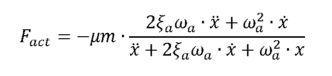
Matemáticamente, esta estrategia propone introducir una fuerza de amortiguamiento activo (Fact) que es función de la frecuencia (Wa ) y del amortiguamiento relativo (£a ) deseado en la masa pasiva virtual, en donde p es la relación entre la masa pasiva virtual y la masa de la máquina (p=ma/m). De acuerdo con ello, con esta estrategia de control alternativa se introduce una fuerza de amortiguamiento activo (Fact) en función de la siguiente ecuación:Mathematically, this strategy proposes to introduce an active damping force ( Fact) that is a function of the frequency (W a ) and the relative damping (£ a ) desired in the virtual passive mass, where p is the ratio between the virtual passive mass and the mass of the machine (p=m a /m). Accordingly, with this alternative control strategy, an active damping force ( Fact) is introduced based on the following equation:

en donde:where:
m es la masa de la máquina rectificadora m is the mass of the grinding machine
p es la relación entre la masa pasiva virtual del actuador y la masa de la máquina (p=ms/m): p is the ratio between the virtual passive mass of the actuator and the mass of the machine ( p=ms/m):
x es el desplazamiento medido debido a las vibracionesx is the measured displacement due to vibrations
Wa es la frecuencia de oscilación deseada en la masa pasiva virtual Wa is the desired oscillation frequency in the virtual passive mass
& es el amortiguamiento relativo deseado en la masa pasiva virtual & is the desired relative damping in the virtual passive mass
De acuerdo con todo ello, se obtiene un proceso para el rectificado de piezas en una máquina rectificadora sin centro que permite mejorar la precisión del rectificado atenuando las vibraciones que se originan en la máquina debido al propio proceso de rectificado.According to all this, a process is obtained for grinding parts in a centerless grinding machine that allows improving the precision of grinding by attenuating the vibrations that originate in the machine due to the grinding process itself.
Descripción de las figurasDescription of the figures
La figura 1 muestra un ejemplo de una máquina rectificadora sin centro en la que es aplicable el proceso de rectificado de la invención.Figure 1 shows an example of a centerless grinding machine in which the grinding process of the invention is applicable.
La figura 2 muestra una vista esquemática de los dos principales modos de vibración de la máquina de la figura 1. La figura 3 muestra una vista esquemática de un actuador dispuesto en serie con el flujo de fuerza de una maquina rectificadora.Figure 2 shows a schematic view of the two main vibration modes of the machine of Figure 1. Figure 3 shows a schematic view of an actuator arranged in series with the force flow of a grinding machine.
La figura 4 muestra una vista como la de la figura anterior, pero con el actuador inercial dispuesto en paralelo al flujo de fuerza de la maquina rectificadora como propone la invención.Figure 4 shows a view like that of the previous figure, but with the inertial actuator arranged in parallel to the force flow of the grinding machine as proposed by the invention.
La figura 5 muestra una comparativa de la fuerza de amortiguamiento empleada en una estrategia de control de cancelación según el estado de la técnica.Figure 5 shows a comparison of the damping force used in a cancellation control strategy according to the state of the art.
La figura 6 muestra una comparativa de la fuerza de amortiguamiento empleada en una estrategia de control de amortiguamiento activo como la propuesta por la invención.Figure 6 shows a comparison of the damping force used in an active damping control strategy such as that proposed by the invention.
Descripción detallada de la invenciónDetailed description of the invention
En la figura 1 se muestra un ejemplo de una máquina rectificadora sin centro en la que es aplicable el proceso de rectificado de la invención. La máquina rectificadora comprende dos ruedas (1, 2), una muela (1) y una rueda reguladora (2), entre las que hay dispuesta una pieza (3) a rectificar apoyada sobre un medio de soporte (4). Cada rueda (1, 2) está dispuesta en un cabezal (5, 6) y cada cabezal (5, 6) está dispuesto en un medio de traslación (8, 9). Figure 1 shows an example of a centerless grinding machine in which the grinding process of the invention is applicable. The grinding machine comprises two wheels (1, 2), a grinding wheel (1) and a regulating wheel (2), between which there is a piece (3) to be grinded supported on a support means (4). Each wheel (1, 2) is arranged in a head (5, 6) and each head (5, 6) is arranged in a translation means (8, 9).
La configuración de máquina representada en la figura 1 no es limitativa para la invención, resultando evidente para un experto en la materia que el proceso de rectificado pudiera aplicarse en máquinas rectificadoras sin centro con una configuración de máquina diferente.The machine configuration represented in Figure 1 is not limiting for the invention, it being evident to a person skilled in the art that the grinding process could be applied in centerless grinding machines with a different machine configuration.
Mediante el desplazamiento de los cabezales (5, 6) se produce un movimiento de separación y aproximación entre las ruedas (1, 2), produciéndose dicho movimiento en una dirección perpendicular a la pieza (3). Así, en funcionamiento, las ruedas (1, 2) aplican presión en la pieza (3) en la dirección del movimiento de aproximación entre ellas (1, 2), de manera que la pieza (3) queda retenida entre las ruedas (1, 2) apoyando en giro libre sobre el medio de soporte (4), con lo que mediante el giro de las ruedas (1, 2) se rectifica la pieza (3).By moving the heads (5, 6), a separation and approximation movement is produced between the wheels (1, 2), said movement occurring in a direction perpendicular to the piece (3). Thus, in operation, the wheels (1, 2) apply pressure on the piece (3) in the direction of the approach movement between them (1, 2), so that the piece (3) is retained between the wheels (1 , 2) supporting in free rotation on the support means (4), thereby grinding the piece (3) by turning the wheels (1, 2).
El propio proceso de rectificado crea fuerzas que excitan los modos de vibración de los diferentes componentes de la máquina, como son los cabezales (5, 6), lo cual genera unas vibraciones que son transmitidas al punto de mecanizado situado en la zona de contacto entre la pieza (3) y las ruedas (1, 2). Esto provoca, entre otros factores, defectos geométricos o desgastes excesivos de herramienta de mecanizado, o un mal acabado superficial de la pieza (3). Como se observa en la figura 2, la máquina rectificadora sin centro tiene dos modos principales de vibración, los cuales provocan una flexión de los cabezales (5, 6) que tiende a su alejamiento o acercamiento. The grinding process itself creates forces that excite the vibration modes of the different components of the machine, such as the heads (5, 6), which generates vibrations that are transmitted to the machining point located in the contact area between the piece (3) and the wheels (1, 2). This causes, among other factors, geometric defects or excessive wear of the machining tool, or a poor surface finish of the part (3). As seen in Figure 2, the centerless grinding machine has two main modes of vibration, which cause a bending of the heads (5, 6) that tends to move them away or towards each other.
La invención propone un proceso de rectificado para máquinas rectificadoras sin centro con el que se pueden atenuar, o incluso eliminar, esas vibraciones debidas al propio proceso de rectificado.The invention proposes a grinding process for centerless grinding machines with which these vibrations due to the grinding process itself can be attenuated, or even eliminated.
Así, el proceso de rectificado propuesto por la invención comprende aproximar las ruedas (1, 2) entre sí aplicando presión en la pieza (3) para su rectificado, medir las vibraciones generadas debidas al rectificado, e introducir, en función de dicha medición, una fuerza de amortiguamiento activo (Fact), que es introducida en paralelo al flujo de fuerza de la máquina rectificadora, y mediante el empleo de un actuador inercial (10) que actúa sobre uno de los cabezales (5, 6), de forma que se atenúan las vibraciones debidas al rectificado.Thus, the grinding process proposed by the invention comprises bringing the wheels (1, 2) closer to each other by applying pressure to the piece (3) for grinding, measuring the vibrations generated due to grinding, and introducing, based on said measurement, an active damping force ( Fact), which is introduced in parallel to the force flow of the grinding machine, and through the use of an inertial actuator (10) that acts on one of the heads (5, 6), so that Vibrations due to grinding are attenuated.
La medición de las vibraciones debidas al rectificado se realiza empleando unos medios de detección (9), tal como, por ejemplo, acelerómetros. Los medios de detección (9) están especialmente configurados para medir bajas frecuencias inferiores a 300 Hz y, preferentemente, un rango de frecuencias entre 10-300 Hz. Para ello, se ha previsto emplear filtros que discriminen el ruido debido a frecuencias fuera del rango preferente anteriormente indicado. The measurement of vibrations due to grinding is carried out using detection means (9), such as, for example, accelerometers. The detection means (9) are specially configured to measure low frequencies below 300 Hz and, preferably, a frequency range between 10-300 Hz. For this, it has been planned to use filters that discriminate noise due to frequencies outside the range. preferred previously indicated.
Como se muestra en el ejemplo de la figura 1, se ha previsto disponer el actuador inercial en la parte superior del cabezal (5, 6), que es la parte de la máquina en donde se produce el mayor desplazamiento debido a las vibraciones del proceso de rectificado.As shown in the example in Figure 1, it has been planned to place the inertial actuator in the upper part of the head (5, 6), which is the part of the machine where the greatest displacement occurs due to the vibrations of the process. of grinding.
Para mejorar la precisión de la máquina, se dispone un actuador inercial (10) en cada cabezal, de manera que se introduce una fuerza de amortiguamiento activo (Fact) en cada cabezal (5, 6).To improve the precision of the machine, an inertial actuator (10) is arranged in each head, so that an active damping force ( Fact) is introduced in each head (5, 6).
Los medios de detección (9) se disponen en el cabezal (5, 6), de manera que los medios de detección (9) y el actuador inercial (10) que introduce la fuerza están colocalizados en el mismo punto.The detection means (9) are arranged in the head (5, 6), so that the detection means (9) and the inertial actuator (10) that introduces the force are located at the same point.
En el ejemplo de la figura 1, las vibraciones se miden en los dos cabezales (5, 6), introduciéndose una fuerza de amortiguamiento activo (Fact) en cada cabezal (5, 6) mediante un respectivo actuador inercial (10), de forma que se atenúan las vibraciones debidas al rectificado en los dos cabezales (5, 6).In the example of Figure 1, the vibrations are measured in the two heads (5, 6), introducing an active damping force ( Fact) in each head (5, 6) by means of a respective inertial actuator (10), so that the vibrations due to grinding in the two heads (5, 6) are attenuated.
En la figura 3 se muestra una vista esquemática de un actuador (9) dispuesto en serie con el flujo de fuerza de la maquina rectificadora, tal y como proponen los documentos del estado de la técnica ES2278496A1, o, JP2005199410A, mientras que en la figura 4 se muestra otra vista esquemática de un actuador inercial (9) dispuesto en paralelo al flujo de fuerza de la maquina rectificadora, tal y como propone la invención.Figure 3 shows a schematic view of an actuator (9) arranged in series with the force flow of the grinding machine, as proposed in the state-of-the-art documents ES2278496A1, or JP2005199410A, while in the figure 4 shows another schematic view of an inertial actuator (9) arranged in parallel to the force flow of the grinding machine, as proposed by the invention.
El flujo de fuerza de la maquina rectificadora, también denominado "path force", está representado en las figuras por una línea con flechas. Este flujo se refiere al camino que seguiría la transmisión de la fuerza necesaria para el rectificado de las piezas dentro de la máquina.The force flow of the grinding machine, also called "path force", is represented in the figures by a line with arrows. This flow refers to the path that the transmission of the force necessary for grinding the parts within the machine would follow.
Cuando el actuador se dispone en serie, tal y como proponen los documentos ES2278496A1 o JP2005199410A, al pasar el flujo de fuerza por el actuador, el actuador puede modificar las propiedades dinámicas originales de la máquina y así amortiguar las vibraciones creadas, al mismo tiempo que tiene que soportar las fuerzas de rectificado. Por ello, la rigidez que deben aportar los actuadores dispuestos en serie es muy grande y en el caso de que el actuador falle, la máquina no rectificaría apropiadamente.When the actuator is arranged in series, as proposed in documents ES2278496A1 or JP2005199410A, when the force flow passes through the actuator, the actuator can modify the original dynamic properties of the machine and thus dampen the vibrations created, at the same time has to withstand the grinding forces. Therefore, the rigidity that the actuators arranged in series must provide is very great and in the event that the actuator fails, the machine would not rectify properly.
En cambio, si el actuador inercial se dispone en paralelo, como propone la invención, la fuerza de amortiguamiento es introducida como si fuera una fuerza externa y no tiene ningún efecto sobre la rigidez original de la máquina. Por ello, aunque el actuador falle, la máquina continuaría teniendo su rigidez original y rectificando de manera correcta. On the other hand, if the inertial actuator is arranged in parallel, as proposed by the invention, the damping force is introduced as if it were an external force and has no effect on the original rigidity of the machine. Therefore, even if the actuator fails, the machine would continue to have its original rigidity and grind correctly.
Según una realización de la invención, para realizar el amortiguamiento activo se emplea una estrategia de control que se basa en medir la velocidad de la vibración del cabezal (5, 6) y aplicar mediante el actuador inercial (10) una fuerza proporcional a la amplitud de esa velocidad.According to one embodiment of the invention, to carry out the active damping, a control strategy is used that is based on measuring the speed of the vibration of the head (5, 6) and applying, by means of the inertial actuator (10), a force proportional to the amplitude. of that speed.
Así, la fuerza requerida por el actuador no sería tan grande como en el caso de la cancelación y no necesitaría del conocimiento de la dinámica de la máquina o del proceso a amortiguar.Thus, the force required by the actuator would not be as great as in the case of cancellation and would not require knowledge of the dynamics of the machine or the process to be damped.
Para eliminar las vibraciones de proceso es muy efectivo el empleo de amortiguamiento activo mediante realimentación tal y como propone la invención, cuyo objetivo es dotar a la máquina de una rigidez dinámica más alta en función de la vibración medida. Esta estrategia de realimentación no es válida para vibraciones forzadas constantes, como es el caso de la vibración debida al desequilibrio de rueda, pero sí que es muy efectiva frente a las vibraciones de proceso, ya que el aumentar la rigidez dinámica de la máquina hace que estas vibraciones puedan ser totalmente atenuadas empleando una fuerza menor a la fuerza de vibración.To eliminate process vibrations, the use of active damping through feedback, as proposed by the invention, is very effective, the objective of which is to provide the machine with a higher dynamic rigidity depending on the measured vibration. This feedback strategy is not valid for constant forced vibrations, such as vibration due to wheel imbalance, but it is very effective against process vibrations, since increasing the dynamic rigidity of the machine makes it These vibrations can be completely attenuated by using a force less than the vibration force.
Según otra realización de la invención, para realizar el amortiguamiento activo se emplea una estrategia de control que se basa en un modelo dinámico de la máquina para hacer al actuador inercial comportarse como un amortiguador pasivo (tuned mass damper). Este amortiguador pasivo virtual podría atenuar diferentes frecuencias y puede ser diseñado para simular diferentes magnitudes de masa, eliminando así las desventajas de los amortiguadores pasivos. Además, la fuerza requerida al actuador también sería bastante menor que la exigida en la cancelación, ya que también se basa en una realimentación de los parámetros de vibración. Aunque la necesidad del modelo dinámico lo hace menos atractiva frente a la simple realimentación, el hecho de que el comportamiento dinámico no varíe según la posición de sus componentes hace que no sea necesario ajustar el modelo en cada proceso, ya que la estrategia de control no requiere del conocimiento de las condiciones del proceso de rectificado.According to another embodiment of the invention, to carry out active damping, a control strategy is used that is based on a dynamic model of the machine to make the inertial actuator behave as a passive damper ( tuned mass damper). This virtual passive damper could attenuate different frequencies and can be designed to simulate different magnitudes of mass, thus eliminating the disadvantages of passive dampers. Furthermore, the force required from the actuator would also be considerably less than that required in the cancellation, since it would also It is based on a feedback of the vibration parameters. Although the need for the dynamic model makes it less attractive compared to simple feedback, the fact that the dynamic behavior does not vary according to the position of its components means that it is not necessary to adjust the model in each process, since the control strategy does not requires knowledge of the conditions of the grinding process.
A continuación, se muestra una tabla comparativa entre una estrategia de control basada en la cancelación, como es el caso de los documentos JP2005199410A o JP2002254303A, y una estrategia de control basada en amortiguamiento activo, como es el caso de las dos estrategias propuestas por la presente invención.Below is a comparative table between a control strategy based on cancellation, as is the case of documents JP2005199410A or JP2002254303A, and a control strategy based on active damping, as is the case of the two strategies proposed by the present invention.
Como se puede observar, entre otros aspectos ventajosos, en el caso del amortiguamiento activo la fuerza requerida por el actuador inercial es bastante menor que la exigida en la cancelación y, además, la cancelación es una estrategia pre-control en donde se requiere un conocimiento preciso de la vibración a cancelar, mientras que el amortiguamiento activo es una estrategia de realimentación en donde no es necesario tener un conocimiento preciso de la vibración para poder atenuarla.As can be seen, among other advantageous aspects, in the case of active damping the force required by the inertial actuator is much lower than that required in cancellation and, in addition, cancellation is a pre-control strategy where knowledge is required. precise vibration to be cancelled, while active damping is a feedback strategy where it is not necessary to have precise knowledge of the vibration to be able to attenuate it.

En la figura 5 se muestra una gráfica comparativa de una estrategia de control de cancelación según el estado de la técnica anterior, en donde la fuerza de amortiguamiento (Fací), representada a trazos, tiene la misma amplitud y fase opuesta a la fuerza (F) que se quiere cancelar, mientras que en la figura 6 se muestra una gráfica comparativa de una estrategia de control amortiguamiento activo, en donde se observa claramente que la fuerza de amortiguamiento (Fací) requerida es menor que la fuerza de amortiguamiento (Fací) empleada para la cancelación. Figure 5 shows a comparative graph of a cancellation control strategy according to the state of the prior art, where the damping force (Fací), represented in dashes, has the same amplitude and opposite phase to the force (F ) that you want to cancel, while Figure 6 shows a comparative graph of an active damping control strategy, where it is clearly observed that the damping force ( Fací) required is less than the damping force ( Fací) used for cancellation.
Claims (12)
Applications Claiming Priority (1)
| Application Number | Priority Date | Filing Date | Title |
|---|---|---|---|
| EP18382825.0A EP3653336B1 (en) | 2018-11-19 | 2018-11-19 | Actively dampened centerless grinding process |
Publications (1)
| Publication Number | Publication Date |
|---|---|
| ES2950908T3 true ES2950908T3 (en) | 2023-10-16 |
Family
ID=64899227
Family Applications (1)
| Application Number | Title | Priority Date | Filing Date |
|---|---|---|---|
| ES18382825T Active ES2950908T3 (en) | 2018-11-19 | 2018-11-19 | Actively damped centerless grinding process |
Country Status (4)
| Country | Link |
|---|---|
| US (1) | US20200156207A1 (en) |
| EP (1) | EP3653336B1 (en) |
| CN (1) | CN111203801B (en) |
| ES (1) | ES2950908T3 (en) |
Families Citing this family (6)
| Publication number | Priority date | Publication date | Assignee | Title |
|---|---|---|---|---|
| CN112059752B (en) * | 2020-09-09 | 2021-11-30 | 马鞍山中金超硬材料科技发展有限公司 | Centerless grinding taper workpiece tool clamp and clamping process thereof |
| KR20230076178A (en) * | 2021-11-24 | 2023-05-31 | 주식회사 디엔솔루션즈 | Active vibration reduction device of machine tool and method thereof |
| CN114871871B (en) * | 2022-04-25 | 2023-07-14 | 深圳大华轴承有限公司 | Centerless grinding machine for precision bearing machining |
| CN117340704A (en) * | 2022-06-28 | 2024-01-05 | 宝山钢铁股份有限公司 | On-line grinding device and grinding method for avoiding vibration marks applied to metallurgical rolls |
| CN115256048B (en) * | 2022-08-10 | 2024-10-01 | 九江金铖科技有限公司 | High-safety mechanical vibration measuring device with multi-position detection function |
| KR102774250B1 (en) * | 2022-11-04 | 2025-02-27 | 한국해양과학기술원 | High precision cnc machining center for model ship manufacturing using active vibration control technology |
Family Cites Families (19)
| Publication number | Priority date | Publication date | Assignee | Title |
|---|---|---|---|---|
| US4663892A (en) * | 1982-11-30 | 1987-05-12 | Energy Adaptive Grinding, Inc. | Force-controlled steadyrest system |
| US5643051A (en) * | 1995-06-16 | 1997-07-01 | The University Of Connecticut | Centerless grinding process and apparatus therefor |
| US6729938B2 (en) * | 2000-05-29 | 2004-05-04 | Koyo Machine Industries Co., Ltd. | Centerless grinding machine |
| GB0024933D0 (en) * | 2000-10-11 | 2000-11-29 | Douglas Curtis Ltd | Improvements in cylindrical grinding |
| JP2002254303A (en) | 2001-02-23 | 2002-09-10 | Toyoda Mach Works Ltd | Finishing device |
| JP2005199410A (en) | 2004-01-19 | 2005-07-28 | Japan Science & Technology Agency | Vibration control method and vibration control device for grinding machine with grinding wheel and machine tool with rotary blade |
| EP1722922B1 (en) * | 2004-02-19 | 2007-08-15 | Salvatore Vaccaro | Centerless grinder |
| ES2278496B1 (en) | 2005-05-09 | 2008-06-16 | Estarta Rectificadora, S.Coop | System for active control of auto excited vibrations in machine-tool, comprises spindle nut, which is arranged between nuts of displacement assembly, active actuator elements and sensors of mechanical tension |
| AT502377B1 (en) * | 2005-09-26 | 2007-03-15 | Asen Norbert Ing | BASE BODY FOR A ROTATING GRINDING OR FIG. CUTTING TOOL, AND GRINDING MACHINE MANUFACTURED THEREFROM. CUTTING TOOL |
| US7677954B2 (en) * | 2007-05-21 | 2010-03-16 | Hall David R | O.D. centerless grinding machine |
| JP2013230544A (en) * | 2012-04-05 | 2013-11-14 | Hitachi Ltd | Machining method of machine tool, machine tool, and mobile dynamic vibration absorber |
| ES2520466T3 (en) * | 2012-09-13 | 2014-11-11 | Ideko, S. Coop | Inertial shock absorber for vibration suppression in machine tools |
| ES2425994B1 (en) * | 2013-06-03 | 2014-06-20 | Soraluce, S. Coop. | Dynamically stable milling machine tool head |
| DE102014106926A1 (en) * | 2014-05-16 | 2015-11-19 | Schaudt Mikrosa Gmbh | Damping device for a spindle of a grinding machine and grinding machine with a damping device |
| DE102014115149B3 (en) * | 2014-10-17 | 2016-01-21 | Schaudt Mikrosa Gmbh | Grinding machine, in particular compact designed centerless grinder |
| EP3078452A1 (en) * | 2015-04-09 | 2016-10-12 | Ideko, S. Coop | System for suppressing chatter in a machine tool |
| CN106392753B (en) * | 2016-05-11 | 2018-06-26 | 西安交通大学 | A kind of intelligence milling electro spindle active cutting-vibration suppression system and method online |
| JP6408512B2 (en) * | 2016-05-27 | 2018-10-17 | ミクロン精密株式会社 | Centerless grinding machine and control method thereof |
| EP3412407B1 (en) * | 2017-06-05 | 2020-01-01 | Ideko, S. Coop | Dynamically dampened centerless grinding machine tool and grinding method |
-
2018
- 2018-11-19 EP EP18382825.0A patent/EP3653336B1/en active Active
- 2018-11-19 ES ES18382825T patent/ES2950908T3/en active Active
-
2019
- 2019-11-04 US US16/672,902 patent/US20200156207A1/en not_active Abandoned
- 2019-11-15 CN CN201911118010.4A patent/CN111203801B/en not_active Expired - Fee Related
Also Published As
| Publication number | Publication date |
|---|---|
| CN111203801A (en) | 2020-05-29 |
| US20200156207A1 (en) | 2020-05-21 |
| CN111203801B (en) | 2023-10-03 |
| EP3653336A1 (en) | 2020-05-20 |
| EP3653336B1 (en) | 2023-05-03 |
Similar Documents
| Publication | Publication Date | Title |
|---|---|---|
| ES2950908T3 (en) | Actively damped centerless grinding process | |
| ES2630952T3 (en) | Dynamically stable machine tool | |
| ES2719927B2 (en) | TOOL MACHINE WITH ACTIVE AMORTIGUATION | |
| RU2618794C1 (en) | Vibration damper for high loads | |
| CN109311134B (en) | Machining device and method with vibration damping device | |
| KR20200052325A (en) | Tower vibration damper | |
| JPH05222863A (en) | Vibration control device for structures | |
| ES2724403T3 (en) | Machine tool with active damping system | |
| Shin et al. | Active vibration control of clamped beams using positive position feedback controllers with moment pair | |
| ES2425994B1 (en) | Dynamically stable milling machine tool head | |
| CN113829116B (en) | Vibration reduction systems and machine tools | |
| Albizuri et al. | An active system of reduction of vibrations in a centerless grinding machine using piezoelectric actuators | |
| ES2783825T3 (en) | Dynamically Damped Centerless Grinding Machine Tool and Grinding Method | |
| EP2500231A1 (en) | Rail vehicle unit with a rolling support | |
| JP2023514669A (en) | Tunable clamping device to reduce vibration of clamped workpieces | |
| KR20120069195A (en) | Apparatus for damping vibration of tool carriage in lathe | |
| JP2020011372A (en) | Machine tool vibration control device | |
| ES2894144T3 (en) | Machine tool with optimized orientation of vibration dampers | |
| Rusli et al. | Dynamic vibration absorber for squeal noise suppression in simple model structures | |
| PT862700E (en) | MAGNETIC SUPPORT | |
| ES2724799B2 (en) | VERTICAL LATHE WITH DAMPER VIBRATION ABSORBER | |
| ES2200918T3 (en) | SUSPENSION FOR A MOTOR UNIT. | |
| WO2019202542A1 (en) | Engine vibration absorber | |
| KIM et al. | Analysis of the Reduction of the Dynamic Response for the CNC 5 Axles Machining Center | |
| JP2011106590A (en) | Parallel plate spring type dynamic vibration absorber |