JP2000250102A5 - - Google Patents
Download PDFInfo
- Publication number
- JP2000250102A5 JP2000250102A5 JP1999050704A JP5070499A JP2000250102A5 JP 2000250102 A5 JP2000250102 A5 JP 2000250102A5 JP 1999050704 A JP1999050704 A JP 1999050704A JP 5070499 A JP5070499 A JP 5070499A JP 2000250102 A5 JP2000250102 A5 JP 2000250102A5
- Authority
- JP
- Japan
- Prior art keywords
- incident surface
- incident
- light
- shape
- axis
- Prior art date
- Legal status (The legal status is an assumption and is not a legal conclusion. Google has not performed a legal analysis and makes no representation as to the accuracy of the status listed.)
- Granted
Links
- 230000003287 optical effect Effects 0.000 description 5
- 238000002347 injection Methods 0.000 description 1
- 239000007924 injection Substances 0.000 description 1
Images
Description
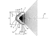
光学プリズム11の被写体側の前面には、左右方向(X方向)の配光特性を制御するプリズム面11dが形成されている。また、上下方向(Y方向)の配光特性の制御は、主に照射光軸前方に射出された光束を入射させ屈折によって所望の配光特性に変換させる正面入射面11aと、主に照射光軸に対して上下方向に射出された成分を入射させる上方入射面11b、上方入射面11bから入射した光束を全反射させる全反射面11cによって行われている。形状に関しては後で詳しく説明する。 A prism surface 11d for controlling the light distribution characteristics in the left-right direction (X direction) is formed on the front surface of the optical prism 11 on the subject side. Further, the control of the light distribution characteristics in the vertical direction (Y direction) is mainly performed by the front incident surface 11a, which incidents a light beam emitted in front of the irradiation light axis and converts it into a desired light distribution characteristic by refraction, and mainly the irradiation light. is performed by the total reflection surface 11c for totally reflecting upper incident surface 11b for entering the injected components in the vertical direction, the light beam incident from the upper side incident surface 11b with respect to the axis. The shape will be described in detail later.
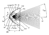
次に、光学プリズム1の全反射面1cに入射光を導く第2の入射面1bの形状を決定する。この第2の入射面1bの形状として、光学プリズムの形状を最小にするためには、光軸1Zと平行な平面であることが望ましい。 Next, to determine the shape of the second incident surface 1b for guiding incident light to the total reflection surface 1 c of the optical prism 1. The shape of the second incident surface 1b is preferably a plane parallel to the optical axis 1Z in order to minimize the shape of the optical prism.
また、入射面8b,8b′の角度φ、各入射面で制御後のそれぞれ射出最大角度の関係、さらに、入射面の境界線と光源中心とを結んだ線分と射出光軸となす角度θbdrとすると、本実施形態はそれぞれ以下の値をとった時の状態を示したものである。
φ=0°|β max /α max |=1.0 θ bdr =38.6°
Further, the angle φ of the incident surfaces 8b and 8b' , the relationship between the maximum injection angles after control at each incident surface, and the angle θ formed by the line segment connecting the boundary line of the incident surface and the center of the light source and the emission optical axis. Assuming bdr , this embodiment shows the state when the following values are taken.
φ = 0 ° | β max / α max | = 1.0 θ bdr = 38.6 °
Priority Applications (1)
| Application Number | Priority Date | Filing Date | Title |
|---|---|---|---|
| JP05070499A JP4208325B2 (en) | 1999-02-26 | 1999-02-26 | Illumination device and photographing device using the same |
Applications Claiming Priority (1)
| Application Number | Priority Date | Filing Date | Title |
|---|---|---|---|
| JP05070499A JP4208325B2 (en) | 1999-02-26 | 1999-02-26 | Illumination device and photographing device using the same |
Publications (3)
| Publication Number | Publication Date |
|---|---|
| JP2000250102A JP2000250102A (en) | 2000-09-14 |
| JP2000250102A5 true JP2000250102A5 (en) | 2005-10-20 |
| JP4208325B2 JP4208325B2 (en) | 2009-01-14 |
Family
ID=12866301
Family Applications (1)
| Application Number | Title | Priority Date | Filing Date |
|---|---|---|---|
| JP05070499A Expired - Fee Related JP4208325B2 (en) | 1999-02-26 | 1999-02-26 | Illumination device and photographing device using the same |
Country Status (1)
| Country | Link |
|---|---|
| JP (1) | JP4208325B2 (en) |
Families Citing this family (9)
| Publication number | Priority date | Publication date | Assignee | Title |
|---|---|---|---|---|
| JP4587429B2 (en) * | 2001-07-06 | 2010-11-24 | キヤノン株式会社 | Illumination device and photographing device |
| TW525034B (en) * | 2001-05-10 | 2003-03-21 | Canon Kk | Lighting apparatus and image pickup apparatus |
| JP4035502B2 (en) | 2003-11-28 | 2008-01-23 | キヤノン株式会社 | Illumination optical system and photographing apparatus |
| JP4185856B2 (en) * | 2003-12-12 | 2008-11-26 | キヤノン株式会社 | Illumination device and imaging device |
| JP4366198B2 (en) | 2004-01-23 | 2009-11-18 | キヤノン株式会社 | Illumination optics |
| JP2005284206A (en) * | 2004-03-31 | 2005-10-13 | Canon Inc | Illumination device and photographing device |
| JP4612850B2 (en) | 2005-03-10 | 2011-01-12 | キヤノン株式会社 | Illumination device and photographing device |
| CN103163572A (en) * | 2011-12-08 | 2013-06-19 | 欧司朗股份有限公司 | Lens, light emitting device and scanner |
| CN103775967B (en) * | 2012-10-23 | 2018-05-11 | 欧司朗股份有限公司 | Lens and LED modification lamps |
-
1999
- 1999-02-26 JP JP05070499A patent/JP4208325B2/en not_active Expired - Fee Related
Similar Documents
| Publication | Publication Date | Title |
|---|---|---|
| JPH1056233A5 (en) | ||
| US20130100679A1 (en) | Side illumination lens for led | |
| JP2000250102A5 (en) | ||
| JP2001215448A5 (en) | ||
| JP2004191989A5 (en) | ||
| KR20200036528A (en) | Filtering panel and solar cell module having thereof | |
| JPH01108511A (en) | Coupling optical system between semiconductor laser and optical waveguide | |
| JP2000314831A5 (en) | ||
| JPH1082932A5 (en) | ||
| JP2000294022A5 (en) | ||
| JP2003529788A5 (en) | ||
| JPH11326765A5 (en) | ||
| JPH0536773B2 (en) | ||
| WO2025139003A1 (en) | Vehicle lamp optical element, vehicle lamp module and vehicle | |
| JP2001174740A5 (en) | ||
| JP2005195844A5 (en) | ||
| JP2003207662A5 (en) | ||
| EP1008453A3 (en) | Optical printer head | |
| CN100426091C (en) | Backlight module and light conducting plate | |
| WO2021003770A1 (en) | Combination lens consisting of lens and reflector, and vehicle lamp module comprising same | |
| JP2006251397A5 (en) | ||
| JP2007505336A (en) | Light guide system having a plate-like triangular guide member | |
| JP2000292719A5 (en) | ||
| CN219000554U (en) | Adjustable continuous energy output light guide arm | |
| CN201434256Y (en) | Uniform light generating structure |