JP2000296177A5 - - Google Patents
Download PDFInfo
- Publication number
- JP2000296177A5 JP2000296177A5 JP1999142182A JP14218299A JP2000296177A5 JP 2000296177 A5 JP2000296177 A5 JP 2000296177A5 JP 1999142182 A JP1999142182 A JP 1999142182A JP 14218299 A JP14218299 A JP 14218299A JP 2000296177 A5 JP2000296177 A5 JP 2000296177A5
- Authority
- JP
- Japan
- Prior art keywords
- bell
- chamber
- region
- pressurized air
- conduit
- Prior art date
- Legal status (The legal status is an assumption and is not a legal conclusion. Google has not performed a legal analysis and makes no representation as to the accuracy of the status listed.)
- Granted
Links
- 238000004140 cleaning Methods 0.000 claims description 6
- 238000000889 atomisation Methods 0.000 claims description 4
- 238000007599 discharging Methods 0.000 claims description 3
- 239000012530 fluid Substances 0.000 claims description 3
- 210000003928 nasal cavity Anatomy 0.000 claims 1
- 239000007788 liquid Substances 0.000 description 5
- 239000000693 micelle Substances 0.000 description 3
- 238000007789 sealing Methods 0.000 description 3
- 230000008878 coupling Effects 0.000 description 1
- 238000010168 coupling process Methods 0.000 description 1
- 238000005859 coupling reaction Methods 0.000 description 1
- 230000000994 depressogenic effect Effects 0.000 description 1
- 230000000694 effects Effects 0.000 description 1
- 230000000977 initiatory effect Effects 0.000 description 1
- 230000037431 insertion Effects 0.000 description 1
- 238000003780 insertion Methods 0.000 description 1
- 125000006850 spacer group Chemical group 0.000 description 1
Images
Description
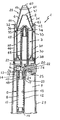
図面について説明する。一般に、この発明の器具は参照番号(1)によって指示され、霧化室(2)、インジェクター(3)、洗浄液を放出する放出手段(4)および圧調節手段(5)よりなる本体を構成する。 The drawings will be described. Generally, the instrument of the present invention is indicated by a reference number (1) and constitutes a main body consisting of an atomizing chamber (2), an injector (3), a discharging means (4) for discharging a cleaning liquid, and a pressure adjusting means (5). ..
本体の内側にある室(6)は、出入口(7)から加圧空気を受け入れる。該室(6)は、加圧空気を放出して圧を調節し、霧化作用の開始を調節するために、第一の導管(8)および第二の導管(9)と共にインジェクター(3)に接続している。 The chamber (6) inside the main body receives pressurized air from the doorway (7). The chamber (6) , together with a first conduit (8) and a second conduit (9), is an injector (3) to release pressurized air to regulate pressure and regulate the initiation of atomization action. Is connected to.
圧調節手段(5)は、シール手段(11)を有し導管(8)の内側を移動するのに適したカーソル(10)を含む。カーソル(10)は、第一の伸縮性の手段、すなわち螺旋形スプリング(12)によって一方に片寄らされる。導管(8)は、シールを確保するためにカーソル(10)と係合し得る領域(13)と、加圧空気を放出するために適切に可変性の直径を有しカーソル(10)の直径よりも大きい導管直径を有する領域(15)に接続する領域(14)とを有する。カーソル(10)の末端は、第1のシール手段すなわちO‐リング(11)のためのシートで中断される4個の隆起部分(18)を有する円筒形をなしている。スプリング(12)の第一の末端は、隆起部分(18)に具備された4個の歯状物(19)に係合するが、スプリング(12)の第二の末端は、カバー(16)と接触している。霧化発生手段は、室(6)、すなわち、第二の伸縮性の手段いい換えれば螺旋形スプリング(24)によって一方に片寄らされる押しボタン(20)によって構成される調節部材の内部に配置され、第二のシール手段は、押しボタン(20)の本体に形成された適当なシート(22)内に配置されるシールまたはガスケット(21)によって構成される。押しボタン(20)は、押しボタンを案内し、器具の本体に当接することによって押しボタンを適所に保つためのスリット(25)と対になった隆起指状部材(26)も有している。The pressure adjusting means (5) includes a cursor (10) having a sealing means (11) and suitable for moving inside the conduit (8). The cursor (10) is offset to one side by the first stretchable means, the spiral spring (12). The conduit (8) has a region (13) that can engage the cursor (10) to ensure a seal and a diameter that is appropriately variable to release pressurized air and is the diameter of the cursor (10). It has a region (14) connecting to a region (15) having a larger conduit diameter. The end of the cursor (10) is cylindrical with four raised portions (18) interrupted by a sheet for the first sealing means, the O-ring (11). The first end of the spring (12) engages the four dentate (19) provided in the raised portion (18), while the second end of the spring (12) is the cover (16). Is in contact with. The atomization generating means is arranged inside a chamber (6), that is, an adjusting member composed of a second elastic means, in other words, a push button (20) offset to one side by a spiral spring (24). The second sealing means is configured by a seal or gasket (21) disposed within a suitable sheet (22) formed in the body of the pushbutton (20). The pushbutton (20) also has a raised finger-like member (26) paired with a slit (25) for guiding the pushbutton and abutting the body of the instrument to hold the pushbutton in place. ..
室(6)は、押しボタン(20)のシート、スリット(25)および導管(9)を経て、室(6)を外部と連通させる開口部(23)によって構成される放出バルブ手段を有する。押しボタン(20)は開口部(23)の内側に伸張し、残りの位置にある部分に部分的に噛み合う。器具(1)の本体は手の握り(27)として働き、実質的に円筒形の形状をした第一の部分を含み、その内部に押しボタンが配置される。この本体は、2個の同軸のベル部材(28)によって構成される第二の部分を含み、ベル部材の一つは鼻孔に挿入するのに適している。この器具の円筒形の手の握り(27)は、2個の密閉するように結合した半分の部材(29および30)によって構成される。押しボタン(20)および圧調節手段(5)は、第一の半分の部材(29)内に配置されるが、インジェクター(3)は、第二の半分の部材(30)内に配置され、ベル部材(28)を結合させるのに適した表面を形成している。穴または空所(4)は、ベル部材(31および32)の間に具備され、その大きさは、広いまたは狭い穴を得るためにベル部材を変えることによって異なる、またはベル部材壁が接触している場合には全く穴がない。第二の半分の部材(30)は、ベル(31)の接続領域での環境に従って配置されたスペーサー部材(33)を有する。 Chamber (6), the sheet of the push button (20), through the slit (25) and conduit (9), having a discharge valve means constituted by the chamber opening through which the (6) externally and communicating (23). The pushbutton (20) extends inward of the opening (23) and partially meshes with the rest of the position. The body of the instrument (1) acts as a hand grip (27) and includes a first portion having a substantially cylindrical shape, within which a push button is arranged. The body includes a second portion composed of two coaxial bell members (28), one of which is suitable for insertion into the nostrils. The cylindrical hand grip (27) of this instrument is composed of two hermetically coupled half members (29 and 30). The push button (20) and the pressure adjusting means (5) are arranged in the first half member (29), while the injector (3) is arranged in the second half member (30). It forms a surface suitable for joining the bell member (28). Holes or voids (4) are provided between the bell members (31 and 32), the size of which varies by changing the bell member to obtain wide or narrow holes, or the bell member walls come into contact. If so, there are no holes. The second half member (30) has a spacer member (33) arranged according to the environment in the connecting region of the bell (31).
第一のベル部材(31)は、一端(35)が半分の部材(30)に結合し、他端(36)は、半分の部材(30)に接触するベース(34)を有する実質的に円錐台の形態をなしている。反対の末端は液体ミセルの噴出のための出口(37)を有している。この発明の別の観点により、このような出口(37)はまた、ベル部材(31)の横の表面に、例えば縦の隙間の形で伸張する。 The first bell member (31) has one end (35) is bonded to the half of the member (30), the other end (36) substantially having a base (34) in contact with half of the member (30) It is in the form of a truncated cone. The opposite end has an outlet (37) for the ejection of liquid micelles. From another aspect of the invention, such an outlet (37) also extends to the lateral surface of the bell member (31) , for example in the form of a vertical gap.
第二のベル部材(32)は第一の円筒形領域(44)を有し、その一端は半分の部材(30)に結合するのに適し、放出される洗浄液収集室(39)を形成する。該収集室(39)のシールは、半分の部材(30)に形成されたシートに配置されたシールまたはガスケット(38)によって提供される。ベル部材(32)の第二の領域は、一端が明確に減少した径を有する先細の領域(41)、次いでミセル噴出出口(40)を具備した一端を有する円錐台の形態(45)をなしている。ベル部材(32)の部品(44および45)の結合領域は、円錐台(45)の壁および円筒形領域(44)から伸張した端(42)によって形成されるチャンネル(46)を有する。円筒形領域(44)のいくらかの可能な振動も突起物(33)によって妨げられる。部材(32)の外壁(45)に恐らく存在する洗浄液を収集するために、チャンネル(46)は収集室(39)を外側と接続する隙間(43)を有する。同じ理由で、ベル(45)は該隙間(43)に向って傾斜したその表面(図面に説明していない)に平面の領域を有しており、汚れた液体の放出を促進する。 The second bell member (32) has a first cylindrical region (44), one end of which is suitable for binding to the half member (30) and forms a discharged cleaning fluid collection chamber (39). .. The seal of the collection chamber (39) is provided by a seal or gasket (38) placed on a sheet formed on the half member (30). The second region of the bell member (32) has the form of a truncated cone (45) with one end having a tapered region (41) with a clearly reduced diameter at one end and then a micelle outlet (40). ing. The coupling region of the parts (44 and 45) of the bell member (32) has a channel (46) formed by the wall of the truncated cone (45) and the end (42) extending from the cylindrical region (44). Some possible vibration of the cylindrical region (44) is also hindered by the protrusions (33). The channel (46) has a gap (43) connecting the collection chamber (39) to the outside in order to collect the cleaning liquid which is probably present on the outer wall (45) of the member (32). For the same reason, the bell (45) has a flat area on its surface (not described in the drawings) that slopes towards the gap (43), facilitating the release of dirty liquids.
押しボタン(20)が押し下げられている状態を考慮する:空気は出入口(7)を経て室(6)に入り、それから開口部(23)を経由する通路は押しボタン(20)によって遮断されるのでインジェクターに進む。この場合、インジェクターノズルを出る空気は、ベンチュリ効果を表すことが可能で、それ故に洗浄液ミセルの噴出物が器具を出る。 Consider the state in which the push button (20) is depressed: air enters the chamber (6) via the inlet (7) and then the passage through the opening (23) is blocked by the push button (20). So proceed to the injector. In this case, the air exiting the injector nozzle can exhibit the Venturi effect, and therefore the ejecta of the cleaning liquid micelles exit the instrument.
Claims (1)
Priority Applications (5)
| Application Number | Priority Date | Filing Date | Title |
|---|---|---|---|
| IT97MI002348A IT1295352B1 (en) | 1997-10-17 | 1997-10-17 | MICRONIZED NASAL SHOWER APPARATUS |
| US09/174,567 US6135358A (en) | 1997-10-17 | 1998-10-16 | Apparatus for washing the nasal cavities |
| EP99106783A EP1044699A1 (en) | 1997-10-17 | 1999-04-06 | Apparatus for washing the nasal cavities |
| CA002267997A CA2267997C (en) | 1997-10-17 | 1999-04-07 | Apparatus for washing the nasal cavities |
| JP14218299A JP4301635B2 (en) | 1997-10-17 | 1999-04-14 | Nasal irrigator |
Applications Claiming Priority (4)
| Application Number | Priority Date | Filing Date | Title |
|---|---|---|---|
| IT97MI002348A IT1295352B1 (en) | 1997-10-17 | 1997-10-17 | MICRONIZED NASAL SHOWER APPARATUS |
| EP99106783A EP1044699A1 (en) | 1997-10-17 | 1999-04-06 | Apparatus for washing the nasal cavities |
| CA002267997A CA2267997C (en) | 1997-10-17 | 1999-04-07 | Apparatus for washing the nasal cavities |
| JP14218299A JP4301635B2 (en) | 1997-10-17 | 1999-04-14 | Nasal irrigator |
Publications (3)
| Publication Number | Publication Date |
|---|---|
| JP2000296177A JP2000296177A (en) | 2000-10-24 |
| JP2000296177A5 true JP2000296177A5 (en) | 2005-09-15 |
| JP4301635B2 JP4301635B2 (en) | 2009-07-22 |
Family
ID=32096923
Family Applications (1)
| Application Number | Title | Priority Date | Filing Date |
|---|---|---|---|
| JP14218299A Expired - Fee Related JP4301635B2 (en) | 1997-10-17 | 1999-04-14 | Nasal irrigator |
Country Status (5)
| Country | Link |
|---|---|
| US (1) | US6135358A (en) |
| EP (1) | EP1044699A1 (en) |
| JP (1) | JP4301635B2 (en) |
| CA (1) | CA2267997C (en) |
| IT (1) | IT1295352B1 (en) |
Families Citing this family (45)
| Publication number | Priority date | Publication date | Assignee | Title |
|---|---|---|---|---|
| ITBS20010091U1 (en) | 2001-11-12 | 2003-05-12 | Flaem Nuova Spa | DEVICE FOR THE WASHING OF NASAL CAVITIES AND THE COLLECTION OF RETURN LIQUIDS AND CATARRAL MATERIAL. |
| KR100426520B1 (en) * | 2002-02-01 | 2004-04-17 | 주식회사 에스텍 | Nasal cleaner |
| US6907879B2 (en) | 2002-02-04 | 2005-06-21 | Ndt | Agent delivery and aspiration device |
| US20040073178A1 (en) * | 2002-05-16 | 2004-04-15 | Anderson Craig W. | Nasal irrigation fitting |
| US20080220107A1 (en) * | 2002-09-03 | 2008-09-11 | Pharmacure Health Care Ab | Nasal spray apparatus |
| US20060024185A1 (en) * | 2002-09-03 | 2006-02-02 | Aakerman Aake | Nasal sprays |
| US20060034939A1 (en) * | 2002-12-09 | 2006-02-16 | The Mollennium Laboratories | Body cavity washer, device for washing body cavity and method of washing body cavity |
| KR100586411B1 (en) | 2004-02-24 | 2006-06-08 | 성신공업 주식회사 | Dog Washing Machine |
| ITBS20050089A1 (en) * | 2005-07-21 | 2007-01-22 | Markos Mefar S P A | DEVICE FOR THE ADMINISTRATION OF LIQUIDS IN NEBULIZED FORM |
| WO2007077548A1 (en) * | 2006-01-03 | 2007-07-12 | Ema Innovation Llc | Computer display viewing support |
| ITBS20080081A1 (en) * | 2008-04-15 | 2009-10-16 | Flaem Nuova Spa | DEVICE FOR WASHING NASAL CAVITIES WITH BUILT-IN PUMP |
| US9440020B2 (en) | 2009-12-08 | 2016-09-13 | Medinvent, Llc | Nasal irrigator |
| US20120000460A1 (en) * | 2010-07-01 | 2012-01-05 | Flickinger William J | Method and Device for Nasal Drug Delivery and Nasal Irrigation |
| WO2011075604A1 (en) * | 2009-12-16 | 2011-06-23 | Water Pik, Inc. | Bottle for sinus cavity rinse |
| US9061096B2 (en) | 2009-12-16 | 2015-06-23 | Water Pik, Inc. | Powered irrigator for sinus cavity rinse |
| USD653953S1 (en) | 2009-12-16 | 2012-02-14 | Water Pik, Inc. | Squeeze bottle |
| US8486029B2 (en) * | 2009-12-16 | 2013-07-16 | Water Pik, Inc. | Pot for sinus cavity rinse |
| USD676126S1 (en) | 2010-06-25 | 2013-02-12 | Water Pik, Inc. | Faceted nasal seal |
| US8888752B2 (en) | 2009-12-16 | 2014-11-18 | Water Pik, Inc. | Bottle for sinus cavity rinse |
| US8991660B2 (en) * | 2009-12-16 | 2015-03-31 | Water Pik, Inc. | Squeeze bottle for sinus cavity rinse |
| USD676125S1 (en) | 2010-06-25 | 2013-02-12 | Water Pik, Inc. | Faceted nasal seal with bottom rim |
| CA2779692A1 (en) * | 2010-02-26 | 2011-09-01 | Byung Eun Yoo | Portable enema device |
| US8409152B2 (en) | 2010-06-25 | 2013-04-02 | Water Pik, Inc. | Faceted nasal seal |
| US9402947B2 (en) | 2010-07-01 | 2016-08-02 | Medinvent, Llc | Portable fluid delivery system for the nasal and paranasal sinus cavities |
| US20160339188A1 (en) * | 2010-07-01 | 2016-11-24 | Medinvent, Llc | Portable Fluid Delivery System for the Nasal and Paranasal Sinus Cavities |
| CH703974A1 (en) | 2010-10-15 | 2012-04-30 | Medmix Systems Ag | Medical spray head with pressure gas support. |
| USD670373S1 (en) | 2010-12-16 | 2012-11-06 | Water Pik, Inc. | Powered irrigator for sinus cavity rinse |
| US10682331B2 (en) | 2012-02-24 | 2020-06-16 | Nasoneb, Inc. | Nasal drug delivery and method of making same |
| US10478547B2 (en) * | 2012-10-30 | 2019-11-19 | Preva, Llc. | Irrigation assembly |
| US11980352B2 (en) | 2012-10-30 | 2024-05-14 | Preva, Llc | Nasal irrigation diagnostic assembly |
| US9433724B2 (en) * | 2012-10-30 | 2016-09-06 | Preva, Llc. | Irrigation assembly |
| US11179513B2 (en) * | 2012-10-30 | 2021-11-23 | Preva, Llc | Irrigation assembly |
| EP2732881B1 (en) | 2012-11-14 | 2015-05-06 | Air Liquide Medical Systems S.p.A. | Micro nebulizer for nasal cleaning or treatment |
| CN102973405B (en) * | 2012-11-30 | 2014-10-15 | 东莞英华融泰医疗科技有限公司 | Nasal irrigation device provided with opening/closing nozzle |
| US10493226B2 (en) | 2013-03-15 | 2019-12-03 | Seedlings Life Science Ventures, Llc | System and assembly for inflating and monitoring pressure within a retaining cuff |
| US11311706B2 (en) | 2014-02-13 | 2022-04-26 | Preva, Llc | Nasal irrigation assembly and system |
| US10265462B2 (en) | 2014-02-13 | 2019-04-23 | Preva, Llc. | Nasal irrigation assembly and system |
| US9289547B2 (en) | 2014-02-13 | 2016-03-22 | Preva, Llc | Nasal irrigation assembly and system |
| USD763434S1 (en) | 2014-12-22 | 2016-08-09 | Medinvent, Llc | Intranasal therapy delivery system |
| CN104784034B (en) * | 2015-03-20 | 2017-01-11 | 马美英 | Nasal cavity postoperative care instrument |
| US9961940B2 (en) * | 2016-01-22 | 2018-05-08 | Funai Electric Co., Ltd. | Vaporizing assembly and vapor generating device |
| CN108010014B (en) * | 2017-11-06 | 2018-10-09 | 蒙城县众扶医联医疗器械有限公司 | A kind of nasal cavity dirt real-time detection method |
| CN111760162B (en) * | 2020-06-18 | 2021-05-07 | 中国人民解放军总医院 | A renal drainage tube device |
| US20240156442A1 (en) * | 2021-03-26 | 2024-05-16 | Board Of Regents Of The University Of Nebraska | Nasal specimen collection system |
| EP4144392A1 (en) | 2021-09-06 | 2023-03-08 | Air Liquide Medical Systems S.R.L. | Aerosoltherapy device comprising a housing made of biopolymeric material |
Family Cites Families (11)
| Publication number | Priority date | Publication date | Assignee | Title |
|---|---|---|---|---|
| US1822743A (en) * | 1927-08-06 | 1931-09-08 | Frederick G Mitchell | Atomizer or sprayer |
| US2546214A (en) * | 1947-03-17 | 1951-03-27 | Harold E Curry | Applicator |
| US2744663A (en) * | 1950-11-01 | 1956-05-08 | Hagan Corp | Burette assembly |
| US3647143A (en) * | 1970-04-06 | 1972-03-07 | Champion Spark Plug Co | Atomizer |
| DE3022913A1 (en) * | 1980-06-19 | 1981-12-24 | Alfred Dipl.-Volksw. 8135 Söcking Becker | Atomiser unit with pressure vessel - has pluggable compressed air charger and atomising head with nozzle and non-return valve |
| FR2539395A1 (en) * | 1983-01-13 | 1984-07-20 | Oreal | CONTAINER FOR DRIPPING A DOSE OF FLUID SUBSTANCE |
| US4940185A (en) * | 1988-12-09 | 1990-07-10 | Fu Hsueh Chin | Safety exhaust valve equipped spray gun |
| US5328061A (en) * | 1992-11-18 | 1994-07-12 | Jeffrey M. Libit | Sliding dispensing cap and dispensing stopper |
| IT1266794B1 (en) * | 1993-11-09 | 1997-01-21 | Faustino Ballini | MICRONIZED SHOWER DEVICE FOR WASHING THE NASAL AND NEIGHBORING CAVITIES |
| IT1275907B1 (en) * | 1995-03-14 | 1997-10-24 | Mefar Srl | MICRONIZED SHOWER DEVICE FOR WASHING THE NASAL AND NEIGHBORING CAVITIES |
| US5655686A (en) * | 1995-05-30 | 1997-08-12 | Jermyn; Arthur Charles | Device for unidirectionally dispensing a hygienic cleaning liquid |
-
1997
- 1997-10-17 IT IT97MI002348A patent/IT1295352B1/en active IP Right Grant
-
1998
- 1998-10-16 US US09/174,567 patent/US6135358A/en not_active Expired - Lifetime
-
1999
- 1999-04-06 EP EP99106783A patent/EP1044699A1/en not_active Withdrawn
- 1999-04-07 CA CA002267997A patent/CA2267997C/en not_active Expired - Fee Related
- 1999-04-14 JP JP14218299A patent/JP4301635B2/en not_active Expired - Fee Related
Similar Documents
| Publication | Publication Date | Title |
|---|---|---|
| JP2000296177A5 (en) | ||
| JP4301635B2 (en) | Nasal irrigator | |
| JP4327794B2 (en) | Atomizer nozzle | |
| JPH06285168A (en) | Liquid atomizer | |
| EP1325782A3 (en) | Improved flat fan spray nozzle | |
| JP2008132495A (en) | Liquid droplet spray device | |
| US7967224B2 (en) | Spray head for atomizing a medium | |
| CA2046339A1 (en) | Liquid jet blower | |
| EP1484115A3 (en) | High frequency ultrasonic nebuliser for hot liquids | |
| EP0896949A4 (en) | AIR / OZONE MIXER AND OZONE MELTER PRODUCER | |
| CA2368082A1 (en) | Liquid mist fire extinguisher | |
| CA2238301A1 (en) | Smoke generating apparatus | |
| JP2011212665A (en) | Two-fluid nozzle and atomizing device provided with two-fluid nozzle | |
| RU97117774A (en) | MULTI-NOZZLE LIQUID-GAS INJECTOR UNIT (OPTIONS) | |
| DE60121505D1 (en) | Charging valve for gas | |
| DE59207691D1 (en) | Discharge nozzle for media | |
| US2396204A (en) | Nebulizer | |
| EP0845300A3 (en) | Liquid atomizing nozzle | |
| KR100610420B1 (en) | Nasal Wash Device | |
| US970576A (en) | Atomizer. | |
| CN113613794A (en) | Atomization device | |
| SU820891A1 (en) | Acoustic nozzle | |
| TW200637657A (en) | Liquid atomizer | |
| TWI755584B (en) | Atomizing device | |
| EP0689878A1 (en) | Dispensing apparatus |