JP2004011004A - Hydrogen storage alloy powder, method for producing the same, and nickel-metal hydride storage battery using the same - Google Patents
Hydrogen storage alloy powder, method for producing the same, and nickel-metal hydride storage battery using the same Download PDFInfo
- Publication number
- JP2004011004A JP2004011004A JP2002169043A JP2002169043A JP2004011004A JP 2004011004 A JP2004011004 A JP 2004011004A JP 2002169043 A JP2002169043 A JP 2002169043A JP 2002169043 A JP2002169043 A JP 2002169043A JP 2004011004 A JP2004011004 A JP 2004011004A
- Authority
- JP
- Japan
- Prior art keywords
- hydrogen storage
- storage alloy
- alloy powder
- nickel
- hydrogen
- Prior art date
- Legal status (The legal status is an assumption and is not a legal conclusion. Google has not performed a legal analysis and makes no representation as to the accuracy of the status listed.)
- Pending
Links
Images
Classifications
-
- Y—GENERAL TAGGING OF NEW TECHNOLOGICAL DEVELOPMENTS; GENERAL TAGGING OF CROSS-SECTIONAL TECHNOLOGIES SPANNING OVER SEVERAL SECTIONS OF THE IPC; TECHNICAL SUBJECTS COVERED BY FORMER USPC CROSS-REFERENCE ART COLLECTIONS [XRACs] AND DIGESTS
- Y02—TECHNOLOGIES OR APPLICATIONS FOR MITIGATION OR ADAPTATION AGAINST CLIMATE CHANGE
- Y02E—REDUCTION OF GREENHOUSE GAS [GHG] EMISSIONS, RELATED TO ENERGY GENERATION, TRANSMISSION OR DISTRIBUTION
- Y02E60/00—Enabling technologies; Technologies with a potential or indirect contribution to GHG emissions mitigation
- Y02E60/10—Energy storage using batteries
Landscapes
- Battery Electrode And Active Subsutance (AREA)
- Powder Metallurgy (AREA)
- Secondary Cells (AREA)
Abstract
【課題】高出力で長寿命のニッケル・水素蓄電池を構成できる水素吸蔵合金粉末およびその製造方法、ならびにそれを用いたニッケル・水素蓄電池を提供する。
【解決手段】ミッシュメタルとニッケルとを含む水素吸蔵合金粉末であって、メジアン径が15μm〜25μmの範囲内であり、ニッケル磁性体の含有率をx(質量%)とし、BET法で測定した比表面積をy(m2/g)としたときに、2≦x≦14且つ0.06x−0.114≦y≦0.06x+0.536を満たす水素吸蔵合金粉末を用いる。
【選択図】 図1The present invention provides a hydrogen storage alloy powder capable of forming a nickel-hydrogen storage battery with high output and long life, a method for producing the same, and a nickel-hydrogen storage battery using the same.
Kind Code: A1 Abstract: A hydrogen storage alloy powder containing misch metal and nickel, having a median diameter in a range of 15 μm to 25 μm and a nickel magnetic substance content of x (% by mass), and measured by a BET method. When the specific surface area is y (m 2 / g), a hydrogen storage alloy powder that satisfies 2 ≦ x ≦ 14 and 0.06x−0.114 ≦ y ≦ 0.06x + 0.536 is used.
[Selection diagram] Fig. 1
Description
【0001】
【発明の属する技術分野】
本発明は、ニッケル・水素蓄電池用の水素吸蔵合金粉末およびその製造方法、ならびにそれを用いたニッケル・水素蓄電池に関する。
【0002】
【従来の技術】
水酸化ニッケルを含む正極と水素吸蔵合金を含む負極とを用いたニッケル・水素蓄電池は、携帯電話やパーソナルコンピュータなどの電源として用いられている。さらに近年では、電気自動車やハイブリッド車の電源として実用化が進められている。
【0003】
ニッケル・水素蓄電池に用いられる水素吸蔵合金について、特性を向上させるための試みが従来からなされている。たとえば、比重1.10以上、温度45℃〜100℃のアルカリ水溶液中に水素吸蔵合金を浸漬する方法が開示されている(特開昭63−146353号公報参照)。この方法によれば、寿命が長い電池が得られることが報告されている。また、特開平11−131160号公報では、磁化、BET比表面積、酸素濃度および粒度分布を限定した水素吸蔵合金粉末を用いた電極が報告されている。また、特開2001−135311号公報では、AB5型の水素吸蔵合金であって、それに含まれるニッケル磁性体量が1.5〜5質量%で且つ比表面積が0.2〜5m2/gの水素吸蔵合金を用いたアルカリ蓄電池が開示されている。このアルカリ蓄電池は、使用開始時の高率放電特性が高いことが報告されている。
【0004】
【発明が解決しようとする課題】
しかしながら、現在、ニッケル・水素蓄電池のさらなる特性向上が求められている。このような状況に鑑み、本発明は、従来のニッケル・水素蓄電池よりもさらに高出力で長寿命のニッケル・水素蓄電池を構成できる水素吸蔵合金粉末およびその製造方法、ならびにそれを用いたニッケル・水素蓄電池を提供することを目的とする。
【0005】
【課題を解決するための手段】
上記目的を達成するために、本発明の水素吸蔵合金粉末は、ミッシュメタルとニッケルとを含む水素吸蔵合金粉末であって、前記水素吸蔵合金粉末のメジアン径が15μm〜25μmの範囲内であり、前記水素吸蔵合金粉末中のニッケル磁性体の含有率をx(質量%)とし、BET法で測定した前記水素吸蔵合金粉末の比表面積をy(m2/g)としたときに、2≦x≦14且つ0.06x−0.114≦y≦0.06x+0.536を満たす。この水素吸蔵合金粉末では、5≦x≦7を満たすことが好ましい。
【0006】
また、水素吸蔵合金粉末の製造するための本発明の方法は、ミッシュメタルとニッケルとを含みメジアン径が15μm〜25μmの範囲内である水素吸蔵合金の粉末を、温度が95℃以上で濃度が40質量%以上の水酸化ナトリウム水溶液に浸漬する浸漬工程を含む。
【0007】
また、本発明のニッケル・水素蓄電池は、水素吸蔵合金粉末を含む負極を備え、前記水素吸蔵合金粉末が上記本発明の水素吸蔵合金粉末である。
【0008】
【発明の実施の形態】
以下、本発明の実施の形態について説明する。
【0009】
(実施形態1)
実施形態1では、本発明の水素吸蔵合金粉末について説明する。実施形態1の水素吸蔵合金粉末は、MmNi5(Mm:ミッシュメタル)を原型とし、Niの一部を他の元素で置換した合金からなる。この合金は、Mmと他の元素とを約1:5の原子比で含む。ミッシュメタルは、LaおよびCeなどの希土類元素の合金である。Niを置換する元素としては、たとえば、Co、Mn、Al、Fe、CuおよびCrから選ばれる少なくとも1つの元素を用いることができる。たとえば、水素吸蔵合金として、Mm、Ni、CoおよびAlを含む合金や、Mm、Ni、Co、AlおよびMnを含む合金や、Mm、Ni、Co、Al、MnおよびFeを含む合金を用いることができる。
【0010】
実施形態1の水素吸蔵合金粉末は、そのメジアン径が15μm〜25μmの範囲内である。メジアン径は、乾式粉砕または湿式粉砕において、粉砕時間や分粒の際に用いるフィルタの目の粗さによって変化させることができる。
【0011】
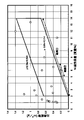
実施形態1の水素吸蔵合金粉末は、その中のニッケル磁性体の含有率をx(質量%)とし、BET法で測定した粉末の比表面積をy(m2/g)としたときに、2≦x≦14且つ0.06x−0.114≦y≦0.06x+0.536を満たす。この領域を、図1の範囲▲1▼に示す。範囲▲1▼を満たすことによって、高出力の水素吸蔵合金電極が得られる。範囲▲1▼の中でも、5≦x≦7を満たす範囲▲2▼は特に好ましい。範囲▲2▼を満たすことによって、出力を向上させ、且つ電池の寿命を向上させることが可能となる。さらに、範囲▲2▼の中でも0.7≦yを満たすことが好ましい。これによって、特に寿命が長い電池を構成できる水素吸蔵合金電極が得られる。
【0012】
また、水素吸蔵合金粉末中のNi含有率は、45質量%〜60質量%の範囲内であることが好ましい。この範囲外であると、ニッケル磁性体による触媒効果が十分に機能しない。Ni含有率が45質量%未満であると、ニッケル磁性体の含有率xを大きくした場合にニッケル以外の元素が酸化される度合いが大きくなり、出力が低下する。また、Ni含有率が60質量%よりも大きいと、出力は良好となるものの水素吸蔵圧が高くなるために内圧特性が悪化し、電池の寿命は短くなる。
【0013】
本明細書のニッケル磁性体の含有率x(質量%)は、特許第2553616号公報に記載された方法で測定した値である。具体的には、試料に磁場を印加して試料の飽和磁化強度を測定することによって測定した値である。試料中のニッケル磁性体(金属状態のニッケル)の量は、飽和磁化強度に比例するため、試料の飽和磁化強度を測定することによって、試料中のニッケル磁性体の含有率を測定できる。
【0014】
通常の水素吸蔵合金は非常に弱い磁性体であるが、これをアルカリ水溶液で処理すると、合金の主成分であるNiや微量成分であるCoなどの一部が、強磁性を有する金属状態に変化する。したがって、アルカリ水溶液で処理した水素吸蔵合金の飽和磁化強度を測定すると、金属状態のNiに基づく磁化強度と、他の強磁性体の磁化強度との合計の値を測定することになる。この明細書では、計測された飽和磁化強度が、金属状態のNiによる飽和磁化強度に等しいと近似している。
【0015】
ニッケル・水素蓄電池の水素吸蔵合金では、充電時に水素を吸蔵し放電時に水素を放出する反応が生じる。このとき、水素吸蔵合金の表面にNi磁性体が存在すると、上記反応が促進される。一方、水素吸蔵合金の表面に存在するNi磁性体の量が多すぎると、高率放電特性が低下する場合もある。したがって、高出力の電池を得るためには、水素吸蔵合金表面のNi磁性体量を適当な範囲に制御する必要がある。実施形態1の水素吸蔵合金粉末は、メジアン径、ニッケル磁性体の含有率、および比表面積を上述した範囲内にすることによって、高出力で長寿命のニッケル・水素蓄電池を構成することが可能である。
【0016】
(実施形態2)
実施形態2では、ニッケル・水素蓄電池用の水素吸蔵合金を製造するための本発明の方法について説明する。実施形態2の方法によれば、実施形態1で説明した水素吸蔵合金を製造できる。
【0017】
以下、実施形態2の製造方法について説明する。まず、製造する水素吸蔵合金の組成比となるように、ミッシュメタルおよびニッケルを含む金属を溶解して合金化し、水素吸蔵合金を得る。その後、この合金を乾式法または湿式法で所定時間粉砕し、得られた合金粉末を所定の粗さのふるいを用いて分級することによって、メジアン径が15μm〜25μmの範囲内である合金粉末を得る。
【0018】
次に、この粉末を、温度が95℃以上で濃度が40質量%以上の水酸化ナトリウム水溶液に浸漬して攪拌する(浸漬工程)。水酸化ナトリウム溶液の温度は、95℃以上で沸点以下である。また、水酸化ナトリウム溶液の濃度は、40質量%以上で溶解度以下である。浸漬時間は、1時間〜3時間程度である。
【0019】
その後、この合金粉末を純水などで洗浄し、乾燥することによってニッケル・水素蓄電池に好適な水素吸蔵合金粉末が得られる。上述した範囲内で処理を行うことによって、実施形態1で説明した水素吸蔵合金を得ることが可能である。
【0020】
なお、上記の浸漬工程では合金粉末に水素が吸蔵され、この水素がのちの乾燥工程で酸素と反応して発熱するため、安全性および生産性が低下する場合がある。したがって、実施形態2の製造方法は、浸漬工程ののちであって乾燥の前に、水素吸蔵合金粉末に吸蔵された水素を、酸化剤を用いて除去(脱水素)する工程(脱水素工程)をさらに含むことが好ましい。具体的には、浸漬工程を経た水素吸蔵合金粉末を過マンガン酸カリウム、二酸化マンガン、硝酸、塩素、過酸化水素または酸素といった酸化剤で処理することによって合金粉末に吸蔵された水素を除去する。たとえば、水素吸蔵合金粉末を過酸化水素水に浸漬すればよい。合金粉末を過酸化水素水に浸漬する場合、合金表面から希土類の水酸化物が脱落する場合があるが、過酸化水素水に少量のアルカリ水溶液を添加することによって、水中に脱落した希土類を合金表面に析出させることができる。
【0021】
また、浸漬工程を経た合金粉末を純水中に浸漬して酸素でバブリングすることによって脱水素工程を行ってもよい。たとえば、浸漬工程を経た合金粉末を上澄み液が中性になるまで水洗する。その後、純水1kgに対して水素吸蔵合金粉末100gの割合で合金粉末を純水中に浸漬し、0.1m3/分の割合で酸素バブリングしながら30分間撹拌処理を行う。このようにして、合金粉末の脱水素を行うことができる。このような脱水素工程を行うことによって、安全に生産性よく実施形態2の製造方法を実施できる。
【0022】
(実施形態3)
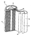
実施形態3では、本発明のニッケル・水素蓄電池について説明する。実施形態3のニッケル・水素蓄電池20について、一部分解斜視図を図2に示す。なお、図2では、円筒形の電池について図示しているが、本発明の電池はこれに限定されず、角形の電池や、電槽に収納された複数の単電池を備える電池であってもよい。
【0023】
図2のニッケル・水素蓄電池20は、ケース21、正極22、負極23、セパレータ24、電解液(図示せず)および封口板25を備える。正極22、負極23およびセパレータ24はコイル状に捲回されて極板群を構成している。極板群および電解液は、封口板25で封口されたケース21内に封入されている。
【0024】
負極23を除く部分は、特に限定がなく、一般的なニッケル・水素蓄電池に使用される部材を用いることができる。たとえば、正極22には、水酸化ニッケルを主な構成材料とする正極を用いることができる。セパレータには、親水化処理を施したポリオレフィン製の不織布を用いることができる。電解液には、水酸化カリウムを主な溶質とする比重が1.3程度のアルカリ水溶液を用いることができる。
【0025】
負極23には、導電性の支持体とその支持体に支持された水素吸蔵合金とを含む負極を用いる。水素吸蔵合金には、実施形態1で説明した水素吸蔵合金を用いる。導電性の支持体には、たとえば、表面をニッケルメッキしたパンチングメタルを用いることができる。負極23は、水素吸蔵合金(および必要に応じて結着剤)を含むペーストを支持体に塗布したのち、乾燥、圧延および切断することによって作製できる。
【0026】
実施形態3のニッケル・水素蓄電池は、実施形態1で説明した水素吸蔵合金を用いているため、高出力で長寿命である。
【0027】
【実施例】
以下、実施例を用いて本発明をさらに詳細に説明する。この実施例では、さまざまな条件で処理した水素吸蔵合金粉末を用いてニッケル・水素蓄電池を作製し、その特性を評価した。
【0028】
水素吸蔵合金粉末は以下の方法で作製した。まず、Ce45質量%、La30質量%、Nd5質量%、および他の希土類元素20質量%が合金化されたミッシュメタルを用意した。そして、このミッシュメタルと、Ni、Co、MnおよびAlとを、MmNi3.5Co0.7Mn0.4Al0.3(Ni含有率:49質量%)の組成になるように配合してアーク溶解炉に入れ、減圧したのち溶解させた。さらに、アルゴンガス雰囲気中において1050℃で8時間熱処理を行い、冷却して水素吸蔵合金を得た。この合金をボールミルで粉砕し、粉砕時間を変化させることによって、メジアン径が異なる合金粉末を作製した。なお、粉末のメジアン径は、レーザを用いた粒度分布測定装置SALD−2000A(島津製作所製)を用いて測定した粉末の粒度分布を用いて決定した。
【0029】
次に、この合金粉末を、溶質、濃度および温度が異なるアルカリ水溶液に2時間浸漬して攪拌した。その後、水洗および乾燥した。このようにして得られた合金粉末について、ニッケル磁性体量と比表面積とを測定した。ここで、ニッケル磁性体量は、振動試料型磁力計VSM−5(東英工業製)を用いて試料中の飽和磁化を測定し、試料中の磁性体が全てニッケルであると仮定して計算した(1emu/g→0.18384質量%)。また、比表面積は、TriStar3000(島津製作所製)を用いてBET8点法で測定した。
【0030】
次に、上記水素吸蔵合金の粉末に、濃度が5質量%のポリビニルアルコール水溶液を加えて混練しペーストを作製した。そして、このペーストをパンチングメタルに塗布し、乾燥、圧延および切断することによって負極を作製した。正極は、発泡ニッケルに、水酸化ニッケルを主成分とする活物質ペーストを充填し、乾燥、圧延および切断することによって作製した。これらの正極および負極を用い、公称容量が5Ahの円筒形ニッケル・水素蓄電池を作製した。このようにして作製したニッケル・水素蓄電池について、直流に対する内部抵抗(DC−IR)と充放電サイクル試験における電池寿命(サイクル寿命)とを測定した。内部抵抗が低いことは、電池の出力が高いことを意味する。各サンプルについて、水素吸蔵合金の処理条件と、内部抵抗およびサイクル寿命の結果とを表1に示す。また、各サンプルのニッケル磁性体量と比表面積とを示すポイントを図1に記載する。
【0031】
【表1】
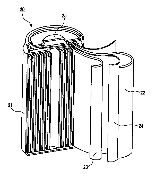
表1から明らかなように、サンプルL〜Pでは、メジアン径が15μm〜25μmの範囲内の水素吸蔵合金を濃度が40質量%以上で温度が95℃以上の水酸化ナトリウム水溶液に浸漬することによって、図1の範囲▲1▼に含まれる水素吸蔵合金が得られた。また、この水素吸蔵合金を用いた電池は、内部抵抗が低くサイクル寿命が長かった。
【0033】
以上、本発明の実施の形態について例を挙げて説明したが、本発明は、上記実施の形態に限定されず本発明の技術的思想に基づき他の実施形態に適用することができる。
【0034】
【発明の効果】
以上のように、本発明の水素吸蔵合金およびその製造方法によれば、高出力で長寿命のニッケル・水素蓄電池を構成できる水素吸蔵合金が得られる。したがって、この水素吸蔵合金を用いた本発明のニッケル・水素蓄電池は、高出力で長寿命である。
【図面の簡単な説明】
【図1】本発明の水素吸蔵合金および実施例の水素吸蔵合金についてNi磁性体量と比表面積との関係を示す図である。
【図2】本発明のニッケル・水素蓄電池の一例を示す一部分解斜視図である。
【符号の説明】
20 ニッケル・水素蓄電池
21 ケース
22 正極
23 負極
24 セパレータ
25 封口板[0001]
TECHNICAL FIELD OF THE INVENTION
The present invention relates to a hydrogen storage alloy powder for a nickel-hydrogen storage battery, a method for producing the same, and a nickel-hydrogen storage battery using the same.
[0002]
[Prior art]
A nickel-metal hydride storage battery using a positive electrode containing nickel hydroxide and a negative electrode containing a hydrogen storage alloy is used as a power source for mobile phones, personal computers, and the like. Furthermore, in recent years, practical use has been promoted as a power source for electric vehicles and hybrid vehicles.
[0003]
Attempts have been made to improve the characteristics of hydrogen storage alloys used in nickel-metal hydride storage batteries. For example, a method of immersing a hydrogen storage alloy in an alkaline aqueous solution having a specific gravity of 1.10 or more and a temperature of 45 ° C. to 100 ° C. has been disclosed (see JP-A-63-146353). According to this method, it is reported that a battery having a long life can be obtained. Japanese Patent Application Laid-Open No. 11-131160 reports an electrode using a hydrogen storage alloy powder having limited magnetization, BET specific surface area, oxygen concentration and particle size distribution. Further, JP-A-2001-135311, JP-A AB 5 type hydrogen storage alloy, and a specific surface area of 0.2~5m 2 / g nickel magnetic weight is 1.5 to 5 wt% it contains An alkaline storage battery using the hydrogen storage alloy of the above is disclosed. It has been reported that this alkaline storage battery has high high-rate discharge characteristics at the start of use.
[0004]
[Problems to be solved by the invention]
However, at present, further improvement of the characteristics of the nickel-metal hydride storage battery is required. In view of such circumstances, the present invention provides a hydrogen storage alloy powder capable of forming a nickel-hydrogen storage battery having a higher output and a longer life than conventional nickel-hydrogen storage batteries, a method for producing the same, and nickel-hydrogen using the same. It is intended to provide a storage battery.
[0005]
[Means for Solving the Problems]
In order to achieve the above object, the hydrogen storage alloy powder of the present invention is a hydrogen storage alloy powder containing misch metal and nickel, and the median diameter of the hydrogen storage alloy powder is in a range of 15 μm to 25 μm, When the content of the nickel magnetic material in the hydrogen storage alloy powder is x (mass%) and the specific surface area of the hydrogen storage alloy powder measured by the BET method is y (m 2 / g), 2 ≦ x Satisfies ≦ 14 and 0.06x−0.114 ≦ y ≦ 0.06x + 0.536. This hydrogen storage alloy powder preferably satisfies 5 ≦ x ≦ 7.
[0006]
Further, the method of the present invention for producing a hydrogen storage alloy powder comprises the steps of: preparing a powder of a hydrogen storage alloy containing misch metal and nickel and having a median diameter in the range of 15 μm to 25 μm at a temperature of 95 ° C. or more and a concentration of 95 ° C. An immersion step of immersing in a 40% by mass or more aqueous sodium hydroxide solution is included.
[0007]
Further, a nickel-hydrogen storage battery of the present invention includes a negative electrode containing a hydrogen storage alloy powder, wherein the hydrogen storage alloy powder is the above-mentioned hydrogen storage alloy powder of the present invention.
[0008]
BEST MODE FOR CARRYING OUT THE INVENTION
Hereinafter, embodiments of the present invention will be described.
[0009]
(Embodiment 1)
Embodiment 1 describes a hydrogen storage alloy powder of the present invention. The hydrogen storage alloy powder according to the first embodiment is made of an alloy in which MmNi 5 (Mm: misch metal) is used as a prototype and Ni is partially substituted with another element. This alloy contains Mm and other elements in an atomic ratio of about 1: 5. Misch metal is an alloy of rare earth elements such as La and Ce. As the element that replaces Ni, for example, at least one element selected from Co, Mn, Al, Fe, Cu, and Cr can be used. For example, as a hydrogen storage alloy, an alloy containing Mm, Ni, Co, Al and Mn, an alloy containing Mm, Ni, Co, Al, Mn and Fe is used. Can be.
[0010]
The hydrogen storage alloy powder of the first embodiment has a median diameter in a range of 15 μm to 25 μm. The median diameter can be changed in dry pulverization or wet pulverization depending on the pulverization time and the roughness of a filter used for sizing.
[0011]
In the hydrogen storage alloy powder of Embodiment 1, when the content of the nickel magnetic material therein is x (mass%) and the specific surface area of the powder measured by the BET method is y (m 2 / g), 2 It satisfies ≦ x ≦ 14 and 0.06x−0.114 ≦ y ≦ 0.06x + 0.536. This area is shown in a range (1) in FIG. By satisfying the range (1), a high-power hydrogen storage alloy electrode can be obtained. Of the range (1), the range (2) satisfying 5 ≦ x ≦ 7 is particularly preferable. By satisfying the range (2), the output can be improved and the life of the battery can be improved. Further, it is preferable that 0.7 ≦ y is satisfied in the range (2). Thereby, a hydrogen storage alloy electrode that can constitute a battery having a particularly long life is obtained.
[0012]
The Ni content in the hydrogen storage alloy powder is preferably in the range of 45% by mass to 60% by mass. If it is outside this range, the catalytic effect of the nickel magnetic material does not function sufficiently. If the Ni content is less than 45% by mass, the degree of oxidation of elements other than nickel increases when the content x of the nickel magnetic material is increased, and the output decreases. On the other hand, if the Ni content is more than 60% by mass, the output becomes good, but the hydrogen storage pressure becomes high, so that the internal pressure characteristics deteriorate and the life of the battery is shortened.
[0013]
The content x (% by mass) of the nickel magnetic substance in the present specification is a value measured by the method described in Japanese Patent No. 25553616. Specifically, it is a value measured by applying a magnetic field to the sample and measuring the saturation magnetization intensity of the sample. Since the amount of the nickel magnetic material (nickel in a metallic state) in the sample is proportional to the saturation magnetization intensity, the content of the nickel magnetic material in the sample can be measured by measuring the saturation magnetization intensity of the sample.
[0014]
Normal hydrogen storage alloys are very weak magnetic materials, but when treated with an alkaline aqueous solution, some of the alloy's main component, Ni and trace components, such as Co, change to a ferromagnetic metal state. I do. Therefore, when the saturation magnetization intensity of the hydrogen storage alloy treated with the alkaline aqueous solution is measured, the total value of the magnetization intensity based on the metallic Ni and the magnetization intensity of the other ferromagnetic material is measured. In this specification, it is approximated that the measured saturation magnetization intensity is equal to the saturation magnetization intensity due to metallic Ni.
[0015]
In a hydrogen storage alloy of a nickel-metal hydride storage battery, a reaction occurs in which hydrogen is stored during charging and released during discharging. At this time, if a Ni magnetic substance exists on the surface of the hydrogen storage alloy, the above reaction is promoted. On the other hand, if the amount of the Ni magnetic material existing on the surface of the hydrogen storage alloy is too large, the high-rate discharge characteristics may be reduced. Therefore, in order to obtain a high-output battery, it is necessary to control the amount of Ni magnetic material on the surface of the hydrogen storage alloy within an appropriate range. By setting the median diameter, the content of the nickel magnetic material, and the specific surface area of the hydrogen storage alloy powder of the first embodiment within the above ranges, it is possible to configure a nickel-hydrogen storage battery with high output and long life. is there.
[0016]
(Embodiment 2)
Embodiment 2 describes a method of the present invention for manufacturing a hydrogen storage alloy for a nickel-metal hydride storage battery. According to the method of the second embodiment, the hydrogen storage alloy described in the first embodiment can be manufactured.
[0017]
Hereinafter, the manufacturing method of the second embodiment will be described. First, a metal containing a misch metal and nickel is melted and alloyed so that the composition ratio of the hydrogen storage alloy to be manufactured is obtained, to obtain a hydrogen storage alloy. Thereafter, the alloy is pulverized for a predetermined time by a dry method or a wet method, and the obtained alloy powder is classified using a sieve having a predetermined roughness, whereby an alloy powder having a median diameter in a range of 15 μm to 25 μm is obtained. obtain.
[0018]
Next, this powder is immersed in an aqueous solution of sodium hydroxide having a temperature of 95 ° C. or higher and a concentration of 40% by mass or higher and stirred (immersion step). The temperature of the sodium hydroxide solution is above 95 ° C. and below the boiling point. Further, the concentration of the sodium hydroxide solution is not less than 40% by mass and not more than the solubility. The immersion time is about 1 hour to 3 hours.
[0019]
Thereafter, the alloy powder is washed with pure water or the like and dried to obtain a hydrogen storage alloy powder suitable for a nickel-metal hydride storage battery. By performing the treatment within the above-described range, the hydrogen storage alloy described in the first embodiment can be obtained.
[0020]
In the above immersion step, hydrogen is occluded in the alloy powder, and the hydrogen reacts with oxygen in the subsequent drying step to generate heat, so that safety and productivity may be reduced. Therefore, in the manufacturing method of Embodiment 2, the step of removing (dehydrogenating) the hydrogen occluded in the hydrogen storage alloy powder using an oxidizing agent after the immersion step and before drying (dehydrogenation step) It is preferable to further include Specifically, the hydrogen occluded in the alloy powder is removed by treating the hydrogen-absorbed alloy powder that has passed through the immersion step with an oxidizing agent such as potassium permanganate, manganese dioxide, nitric acid, chlorine, hydrogen peroxide, or oxygen. For example, the hydrogen storage alloy powder may be immersed in a hydrogen peroxide solution. When the alloy powder is immersed in aqueous hydrogen peroxide, rare earth hydroxides may fall off from the surface of the alloy.However, by adding a small amount of aqueous alkali solution to the aqueous hydrogen peroxide, the rare earths dropped into the water can be alloyed. It can be deposited on the surface.
[0021]
Alternatively, the dehydrogenation step may be performed by immersing the alloy powder having undergone the immersion step in pure water and bubbling with oxygen. For example, the alloy powder that has undergone the immersion step is washed with water until the supernatant becomes neutral. Thereafter, the alloy powder is immersed in pure water at a rate of 100 g of hydrogen storage alloy powder per 1 kg of pure water, and a stirring treatment is performed for 30 minutes while bubbling oxygen at a rate of 0.1 m 3 / min. Thus, dehydrogenation of the alloy powder can be performed. By performing such a dehydrogenation step, the production method of Embodiment 2 can be safely and efficiently performed.
[0022]
(Embodiment 3)
Embodiment 3 describes a nickel-metal hydride storage battery of the present invention. FIG. 2 is a partially exploded perspective view of the nickel-metal
[0023]
The nickel-metal
[0024]
The portion other than the
[0025]
As the
[0026]
The nickel-metal hydride storage battery of the third embodiment uses the hydrogen storage alloy described in the first embodiment, and therefore has a high output and a long life.
[0027]
【Example】
Hereinafter, the present invention will be described in more detail with reference to Examples. In this example, nickel-hydrogen storage batteries were manufactured using hydrogen storage alloy powders treated under various conditions, and their characteristics were evaluated.
[0028]
The hydrogen storage alloy powder was produced by the following method. First, a misch metal prepared by alloying 45 mass% of Ce, 30 mass% of La, 5 mass% of Nd, and 20 mass% of another rare earth element was prepared. Then, this misch metal and Ni, Co, Mn and Al are blended so as to have a composition of MmNi 3.5 Co 0.7 Mn 0.4 Al 0.3 (Ni content: 49% by mass). Then, it was placed in an arc melting furnace, melted after decompression. Further, heat treatment was performed at 1050 ° C. for 8 hours in an argon gas atmosphere, and the mixture was cooled to obtain a hydrogen storage alloy. This alloy was pulverized with a ball mill and the pulverization time was varied to produce alloy powders having different median diameters. The median diameter of the powder was determined using the particle size distribution of the powder measured using a particle size distribution analyzer SALD-2000A (manufactured by Shimadzu Corporation) using a laser.
[0029]
Next, this alloy powder was immersed in an aqueous alkaline solution having a different solute, concentration and temperature for 2 hours and stirred. Then, it was washed with water and dried. With respect to the alloy powder thus obtained, the amount of the nickel magnetic substance and the specific surface area were measured. Here, the amount of nickel magnetic material was calculated by measuring the saturation magnetization in the sample using a vibrating sample magnetometer VSM-5 (manufactured by Toei Kogyo), and assuming that the magnetic material in the sample was all nickel. (1 emu / g → 0.18384 mass%). The specific surface area was measured by a TriStar 3000 (manufactured by Shimadzu Corporation) by the BET 8-point method.
[0030]
Next, an aqueous solution of polyvinyl alcohol having a concentration of 5% by mass was added to the hydrogen storage alloy powder and kneaded to prepare a paste. Then, the paste was applied to a punching metal, dried, rolled, and cut to produce a negative electrode. The positive electrode was manufactured by filling foamed nickel with an active material paste containing nickel hydroxide as a main component, drying, rolling, and cutting. Using these positive and negative electrodes, a cylindrical nickel-metal hydride storage battery having a nominal capacity of 5 Ah was produced. With respect to the nickel-hydrogen storage battery thus manufactured, the internal resistance to direct current (DC-IR) and the battery life (cycle life) in a charge / discharge cycle test were measured. Low internal resistance means that the output of the battery is high. Table 1 shows the processing conditions of the hydrogen storage alloy, the results of the internal resistance and the cycle life of each sample. FIG. 1 shows points indicating the amount of the nickel magnetic substance and the specific surface area of each sample.
[0031]
[Table 1]
As is clear from Table 1, in samples LP, the hydrogen storage alloy having a median diameter in the range of 15 μm to 25 μm is immersed in a sodium hydroxide aqueous solution having a concentration of 40% by mass or more and a temperature of 95 ° C. or more. Thus, a hydrogen storage alloy included in the range (1) of FIG. 1 was obtained. Also, the battery using this hydrogen storage alloy had a low internal resistance and a long cycle life.
[0033]
As described above, the embodiments of the present invention have been described by way of examples. However, the present invention is not limited to the above embodiments, and can be applied to other embodiments based on the technical idea of the present invention.
[0034]
【The invention's effect】
As described above, according to the hydrogen storage alloy and the method for producing the same of the present invention, a hydrogen storage alloy capable of forming a nickel-hydrogen storage battery with high output and long life can be obtained. Therefore, the nickel-hydrogen storage battery of the present invention using this hydrogen storage alloy has a high output and a long life.
[Brief description of the drawings]
FIG. 1 is a view showing the relationship between the amount of Ni magnetic material and the specific surface area of the hydrogen storage alloy of the present invention and the hydrogen storage alloy of the example.
FIG. 2 is a partially exploded perspective view showing an example of the nickel-metal hydride storage battery of the present invention.
[Explanation of symbols]
Claims (6)
前記水素吸蔵合金粉末のメジアン径が15μm〜25μmの範囲内であり、
前記水素吸蔵合金粉末中のニッケル磁性体の含有率をx(質量%)とし、BET法で測定した前記水素吸蔵合金粉末の比表面積をy(m2/g)としたときに、2≦x≦14且つ0.06x−0.114≦y≦0.06x+0.536を満たす水素吸蔵合金粉末。Hydrogen storage alloy powder containing misch metal and nickel,
The median diameter of the hydrogen storage alloy powder is in the range of 15 μm to 25 μm,
When the content of the nickel magnetic material in the hydrogen storage alloy powder is x (mass%) and the specific surface area of the hydrogen storage alloy powder measured by the BET method is y (m 2 / g), 2 ≦ x A hydrogen storage alloy powder satisfying ≦ 14 and 0.06x−0.114 ≦ y ≦ 0.06x + 0.536.
前記水素吸蔵合金粉末が請求項1ないし3のいずれかに記載の水素吸蔵合金粉末であるニッケル・水素蓄電池。A nickel-metal hydride storage battery including a negative electrode including a hydrogen storage alloy powder,
A nickel-metal hydride storage battery, wherein the hydrogen storage alloy powder is the hydrogen storage alloy powder according to any one of claims 1 to 3.
Priority Applications (1)
| Application Number | Priority Date | Filing Date | Title |
|---|---|---|---|
| JP2002169043A JP2004011004A (en) | 2002-06-10 | 2002-06-10 | Hydrogen storage alloy powder, method for producing the same, and nickel-metal hydride storage battery using the same |
Applications Claiming Priority (1)
| Application Number | Priority Date | Filing Date | Title |
|---|---|---|---|
| JP2002169043A JP2004011004A (en) | 2002-06-10 | 2002-06-10 | Hydrogen storage alloy powder, method for producing the same, and nickel-metal hydride storage battery using the same |
Publications (1)
| Publication Number | Publication Date |
|---|---|
| JP2004011004A true JP2004011004A (en) | 2004-01-15 |
Family
ID=30435789
Family Applications (1)
| Application Number | Title | Priority Date | Filing Date |
|---|---|---|---|
| JP2002169043A Pending JP2004011004A (en) | 2002-06-10 | 2002-06-10 | Hydrogen storage alloy powder, method for producing the same, and nickel-metal hydride storage battery using the same |
Country Status (1)
| Country | Link |
|---|---|
| JP (1) | JP2004011004A (en) |
Cited By (2)
| Publication number | Priority date | Publication date | Assignee | Title |
|---|---|---|---|---|
| JP2007115672A (en) * | 2005-09-26 | 2007-05-10 | Matsushita Electric Ind Co Ltd | Electrode alloy powder and method for producing the same |
| JP2010182687A (en) * | 2005-09-26 | 2010-08-19 | Panasonic Corp | Alloy powder for electrode and its manufacturing method |
-
2002
- 2002-06-10 JP JP2002169043A patent/JP2004011004A/en active Pending
Cited By (2)
| Publication number | Priority date | Publication date | Assignee | Title |
|---|---|---|---|---|
| JP2007115672A (en) * | 2005-09-26 | 2007-05-10 | Matsushita Electric Ind Co Ltd | Electrode alloy powder and method for producing the same |
| JP2010182687A (en) * | 2005-09-26 | 2010-08-19 | Panasonic Corp | Alloy powder for electrode and its manufacturing method |
Similar Documents
| Publication | Publication Date | Title |
|---|---|---|
| JP3214341B2 (en) | Manufacturing method of hydrogen storage alloy for batteries | |
| JP2000357508A (en) | Hydrogen storage alloy electrode and method for producing the same | |
| JP2982805B1 (en) | Hydrogen storage alloy for battery, method for producing the same, and alkaline storage battery using the same | |
| JP4815738B2 (en) | Method for producing hydrogen storage alloy powder | |
| JP5388397B2 (en) | Method for improving the properties of alloy powders for NiMH batteries | |
| JPH03152868A (en) | Treatment of hydrogen storage alloy for alkaline second battery | |
| JP4743997B2 (en) | Hydrogen storage alloy electrode | |
| EP1111700B1 (en) | Alkaline storage battery | |
| JP2004011004A (en) | Hydrogen storage alloy powder, method for producing the same, and nickel-metal hydride storage battery using the same | |
| JP3279994B2 (en) | Hydrogen storage alloy powder and negative electrode for alkaline storage battery | |
| JPH06223827A (en) | Manufacture of hydrogen storage alloy powder for battery | |
| JP3387314B2 (en) | Manufacturing method of hydrogen storage alloy electrode | |
| JP3547920B2 (en) | Method for producing hydrogen storage alloy electrode | |
| JP2645889B2 (en) | Method for producing hydrogen storage alloy electrode for alkaline storage battery | |
| KR100405016B1 (en) | Hydrogen Absorbing Alloy Electrode and Method of Producing the Same | |
| JP3825582B2 (en) | Hydrogen storage alloy for alkaline storage battery and method for manufacturing the same, hydrogen storage alloy electrode for alkaline storage battery and method for manufacturing the same | |
| JPH10172550A (en) | Alkaline battery with nickel positive electrode and method of activating the same | |
| JPH1197002A (en) | Hydrogen storage alloy electrode for alkaline storage battery | |
| JPH07153460A (en) | Manufacture of metal hydride electrode | |
| JP2001266860A (en) | Nickel hydrogen storage battery | |
| JP3317099B2 (en) | Hydrogen storage alloy powder for alkaline storage battery, method for producing the same, and method for producing hydrogen storage electrode | |
| JPH11204104A (en) | Nickel-hydrogen secondary battery and method for producing hydrogen storage alloy thereof | |
| JPH04319258A (en) | Hydrogen storage alloy electrode | |
| JP2001006666A (en) | Hydrogen storage alloy for alkaline storage battery and manufacture of such alloy | |
| JP2679441B2 (en) | Nickel-metal hydride battery |
Legal Events
| Date | Code | Title | Description |
|---|---|---|---|
| A621 | Written request for application examination |
Free format text: JAPANESE INTERMEDIATE CODE: A621 Effective date: 20050606 |
|
| A977 | Report on retrieval |
Free format text: JAPANESE INTERMEDIATE CODE: A971007 Effective date: 20061019 |
|
| A131 | Notification of reasons for refusal |
Free format text: JAPANESE INTERMEDIATE CODE: A131 Effective date: 20061130 |
|
| A521 | Request for written amendment filed |
Free format text: JAPANESE INTERMEDIATE CODE: A523 Effective date: 20070123 |
|
| A02 | Decision of refusal |
Free format text: JAPANESE INTERMEDIATE CODE: A02 Effective date: 20070306 |