JP2004014308A - Electronic apparatus - Google Patents
Electronic apparatus Download PDFInfo
- Publication number
- JP2004014308A JP2004014308A JP2002166428A JP2002166428A JP2004014308A JP 2004014308 A JP2004014308 A JP 2004014308A JP 2002166428 A JP2002166428 A JP 2002166428A JP 2002166428 A JP2002166428 A JP 2002166428A JP 2004014308 A JP2004014308 A JP 2004014308A
- Authority
- JP
- Japan
- Prior art keywords
- battery
- lock member
- lock
- electronic device
- housing
- Prior art date
- Legal status (The legal status is an assumption and is not a legal conclusion. Google has not performed a legal analysis and makes no representation as to the accuracy of the status listed.)
- Granted
Links
- 238000003780 insertion Methods 0.000 claims abstract description 20
- 230000037431 insertion Effects 0.000 claims abstract description 20
- 210000000078 claw Anatomy 0.000 claims description 39
- 238000009434 installation Methods 0.000 abstract 3
- 125000002066 L-histidyl group Chemical group [H]N1C([H])=NC(C([H])([H])[C@](C(=O)[*])([H])N([H])[H])=C1[H] 0.000 description 9
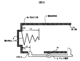
- 230000000694 effects Effects 0.000 description 3
- 230000006835 compression Effects 0.000 description 2
- 238000007906 compression Methods 0.000 description 2
- 230000009191 jumping Effects 0.000 description 2
- 239000000463 material Substances 0.000 description 2
- 230000002093 peripheral effect Effects 0.000 description 2
- 229930182556 Polyacetal Natural products 0.000 description 1
- 238000013480 data collection Methods 0.000 description 1
- 230000005611 electricity Effects 0.000 description 1
- 238000001125 extrusion Methods 0.000 description 1
- 239000004973 liquid crystal related substance Substances 0.000 description 1
- 239000002184 metal Substances 0.000 description 1
- 229920006324 polyoxymethylene Polymers 0.000 description 1
- 239000011347 resin Substances 0.000 description 1
- 229920005989 resin Polymers 0.000 description 1
- 229910001220 stainless steel Inorganic materials 0.000 description 1
Images



Classifications
-
- Y—GENERAL TAGGING OF NEW TECHNOLOGICAL DEVELOPMENTS; GENERAL TAGGING OF CROSS-SECTIONAL TECHNOLOGIES SPANNING OVER SEVERAL SECTIONS OF THE IPC; TECHNICAL SUBJECTS COVERED BY FORMER USPC CROSS-REFERENCE ART COLLECTIONS [XRACs] AND DIGESTS
- Y02—TECHNOLOGIES OR APPLICATIONS FOR MITIGATION OR ADAPTATION AGAINST CLIMATE CHANGE
- Y02E—REDUCTION OF GREENHOUSE GAS [GHG] EMISSIONS, RELATED TO ENERGY GENERATION, TRANSMISSION OR DISTRIBUTION
- Y02E60/00—Enabling technologies; Technologies with a potential or indirect contribution to GHG emissions mitigation
- Y02E60/10—Energy storage using batteries
Landscapes
- Battery Mounting, Suspending (AREA)
Abstract
Description
【0001】
【発明の属する技術分野】
本発明は電子機器に関し、特に駆動用電池を収納する電池収納部を有する電子機器に関するものである。
【0002】
【従来の技術】
従来、この種の電子機器において、電池収納部に挿入されて装着された電池の抜けを防止するために、曲がるように弾性変形可能なロック部材を電池に係合させて電池を保持するようにした構造が特開平10−241648号などにより知られている。その構造は図7及び図8に示すようになっており、電子機器の例えば電池パックとして構成された電池2を収納する電池収納部11に上記のロック部材10が設けられる。ロック部材10は、ロック爪10aを形成した先端部が電池収納部11の電池取り出し方向(図中で右方向)側の端部の開口部11aに臨むように配置され、後端部が電池収納部11の壁に固定される。
【0003】
操作者が電池2を電池収納部11に装着するときには、図8のようにロック爪10aを電池収納部11の開口部11aから退かせるようにロック部材10を指で弾性変形させて、電池2を電池収納部11に挿入し、電池2の給電端子2a,2bが電子機器側の電源端子1a,1bに接続される装着位置まで押し込む。そして、ロック部材10から指を離すことにより、ロック部材10が弾性で元の形状に復帰し、図7のようにロック部材10のロック爪10aが電池2の後端部2eに係合して、電池2が装着位置に保持される。
【0004】
また、電池2を取り出すときには、図7の状態から、ロック爪10aを退かせるようにロック部材10を弾性変形させる。これにより、ロック部材10と電池2の係合が外れ、電池2の保持が解除され、電池収納部11の奥に設けられた電池押出しバネ4の押圧力により、図8のように電池2が電池収納部11の開口部から少し押出される。後は、電池2の後端部2eを指で摘んで電池2を取り出せばよい。
【0005】
【発明が解決しようとする課題】
しかし上記のような従来の構造では以下のような問題があった。
【0006】
1)操作者が電池2を取り出す際に、ロック部材10を退かせるように弾性変形させた後、電池2が電池収納部11から完全に取り出される前にロック部材10から指を離してしまうと、ロック部材10が弾性で元の形状に復帰しようとして、図8に示すように、ロック爪10aが電池2の側面に当接し、ロック部材10の弾性力で圧接する。これにより、両者の接触部Aに摩擦抵抗が生じ、電池2を取り出し方向に移動させにくくなり、操作性が悪い。
【0007】
2)電池2を挿入して装着する際も、ロック部材10を退かせるように弾性変形させた後、電池2を挿入して電池2が装着位置まで挿入される前にロック部材10から指を離してしまうと、同様にロック爪10aが電池2の側面に弾性力で圧接し、電池2を挿入方向に移動させにくくなり、操作性が悪い。
【0008】
3)上記のように操作者が電池2の取り出し又は挿入の途中でロック部材10から指を離さないようにするために、ロック部材10の変形ストロークを大きくすると、電池収納部11の周辺寸法が大きくなり、電子機器の小型化に障害となる。
【0009】
そこで本発明の課題は、この種の電池収納部を有する電子機器において、簡単、安価、しかも小型化が図れる構造で、電池を電池収納部へ挿入して装着する際と取り出す際の操作性を向上することができる構造を提供することにある。
【0010】
【課題を解決するための手段】
上記の課題を解決するため、本発明によれば、
電池で駆動される電子機器において、
前記電池を収納する電池収納部であって、一端側に前記電池の外部からの挿入と外部への取り出しを行うための開口部が形成された電池収納部と、
該電池収納部内の所定の装着位置まで挿入された電池の後端部に係合して電池を装着位置に保持するロック部材であって、前記係合を解除する方向に弾性変形可能なロック部材を有し、
該ロック部材は、一端に前記電池の後端部に係合するロック爪、他端に前記電池の前端部の側面に接触する凸部、中間に回動支点部が形成され、該回動支点部を回動中心として、前記係合を解除する方向に対応する回動方向とその逆の回動方向に回動可能に設けられており、
前記電池収納部に対する電池の装着位置への挿入及び取り出し時に、電池が電池収納部内で装着位置に近い所定位置から装着位置までの領域にある間は、電池の先端部側面が前記ロック部材の凸部に接触することにより、ロック部材が前記係合を可能とする回動位置で前記係合を解除する方向に対応する回動方向に回動できないように拘束され、それにより電池が装着位置まで挿入されたときにロック部材のロック爪が電池の後端部に係合し得るようにした構成を採用した。
【0011】
【発明の実施の形態】
以下、図を参照して本発明の実施の形態を説明する。
【0012】
[第1の実施形態]
本発明の第1の実施形態による電子機器の電池収納部における電池の保持構造を図1〜図5により説明する。
【0013】
まず図1は、本実施形態による電子機器の手前側の部分の外観を概略的に示している。この電子機器1は、上面に液晶表示器12及びキーボード13などが設けられ、内部に不図示の回路基板や印字装置などが設けられており、例えば主に屋外でのデータ収受作業の支援端末としての使用に好適なものである。
【0014】
この電子機器1の手前側には、後述する電池2(図2〜図5参照)を挿入して装着する電池収納部6が設けられており、その一端側で、ここでは電子機器の手前側の右側面には、電池2を外部から挿入するためと外部へ取り出すための開口部6aが形成されている。電池収納部6とその開口部6aの位置はこれに限らないことは勿論である。
【0015】
次に、図2〜図5は、電池収納部6周辺の構造と、電池の挿入、装着及び取り出し動作を説明する断面図である。まず、図2及び図3により構造を説明する。
【0016】
図2において、電池2は、ここでは一例として複数の電池をパックした電池パックとして構成されたものとする。勿論、通常の1つの電池でもよい。電池2の外形形状は、電池収納部6に対する挿入と取り出しに適するように、図2中で左右方向の電池挿入、取り出し方向を長手方向とする真っ直ぐな形状が好ましく、ここでは挿入、取り出し方向を長手方向とする直方体形状としている。電池2の長手方向の一方の端部には、電子機器1に駆動電源を供給するための給電端子2a,2bが設けられており、電池2は、この給電端子2a,2b側の端部2cを先端部(電池挿入方向側の端部)として、先端部2c側から電池収納部6に挿入して装着される。
【0017】
また、電池収納部6の電池挿入方向の奥に形成された壁において、後述する電池押出しバネ4を設けた中央部を除く部分は、挿入した電池2を突き当てて装着位置に位置決めするための突き当て部6bとなっている。この突き当て部6bに電子機器1の本体側の電源端子1a,1bが立設されており、電池2を電池収納部6に挿入し突き当て部6bに突き当てて装着位置に位置決めした際に、電池2の給電端子2a,2bが電源端子1a,1bと接続されて導通するようになっている。
【0018】
一方、電池収納部6の電池挿入、取り出し方向に沿った片方の壁6cの外側近傍には、装着位置まで挿入された電池2に係合して電池2を保持するロック部材3が設けられている。ロック部材3は、曲がるように弾性変形可能なものとして、例えば樹脂材料であればポリアセタールを用いた射出成形部品などとして形成される。
【0019】
また、ロック部材3は、細長い形状に形成されており、長手方向の中間には、回動支点部としてのヒンジ部3a、一方の端部には、後述のように電池2の後端部2eに係合するロック爪3b及び操作者が指をかけてロック部材3を操作するための操作部3d、他方の端部には、後述のように電池2の先端部2cの側面2dに接触する凸部3cが形成されている。ロック爪3bと凸部3cは、ロック部材3の長手方向に沿った片側で前記長手方向に直交する方向に突出している。凸部3cの先端部は半球ないし半円柱形状に形成されており、電池2の先端部2cの側面2dに接触したときの両者間の摩擦抵抗が小さくなるようになっている。操作部3dはロック部材3の長手方向に少しだけ突出している。
【0020】
また、ロック部材3は、電池収納部6の壁6cの外側近傍に設けられたヒンジピン5に対してヒンジ部3aに形成された孔を挿し込ませることにより電子機器に組み付けられ、ヒンジピン5を回動中心、すなわちヒンジ部3aを回動中心として、図2中で時計回り方向と反時計回り方向に回動可能となっている。また、ロック部材3のロック爪3bが電池収納部6の開口部6aに臨み、凸部3cが電池収納部6の壁6cにおいて電池挿入方向の奥寄りに形成された窓6dに臨むように配置されている。そして、ロック部材3の回動により、ロック爪3bと凸部3cが電池収納部6側に向かう方向とその逆方向に、互いに逆方向に変位するようになっている。
【0021】
一方、電池収納部6の挿入方向の奥の壁の中央部には、挿入された電池2を挿入方向と逆の取り出し方向に押圧する弾性部材としての電池押出しバネ4が設けられている。ここでは、電池押出しバネ4は、バネ用ステンレス鋼線等の金属線材料からなる円錐コイルバネとする。電池押出しバネ4は、電池収納部6に挿入される電池2に押圧されて圧縮され、復元(伸長)しようとする弾性力(以下、復元力という)で電池2を取り出し方向に押圧する。
【0022】
この電池押出しバネ4に関して、図3に示すように、電池収納部6に電池2が挿入されておらず、電池押出しバネ4が圧縮されていないフリーな状態で突き当て部6bから電池取り出し方向へ突出する長さ(以下、自由長という)をL1とする。また、突き当て部6bからロック部材3の凸部3cの先端部の位置までの距離をL2とする。本実施形態では、この自由長L1と距離L2との関係が
L1>L2
となるように構成する。すなわち、電池押出しバネ4の圧縮されていない状態での先端の位置がロック部材3の凸部3cの先端部の位置より開口部6a側にあるようにする。なお、距離L2は可能な限り小さく設定し、
L1−L2
の寸法が大きくなるように設計すると電池2の着脱時の操作性が向上することがわかっている。
【0023】
次に、電池の装着及び取り出し動作を図2〜図5により説明する。まず装着動作を説明する。
【0024】
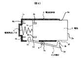
図3に示す電池収納部6に電池2が挿入されていない状態では、ロック部材3は電池収納部6の壁6cに当たらない範囲で回動可能なフリーの状態にある。この状態から操作者が電池2を電池収納部6に挿入して装着するときには、まずロック部材3の操作部3dを指で摘んで、図4に示すようにロック部材3を時計回り方向に回動させてロック爪3bを開口部6aから退かせ、電池2を電池収納部6に対し図中で左方向に挿入する。そして、電池2を突き当て部6bから前述した電池押出しバネ4の自由長L1の距離の位置まで挿入すると、図4に示すように、電池2の先端部2cが電池押出しバネ4に接触する。この時点以後、操作者は、電池押出しバネ4の弾性力に抗して、電池押出しバネ4を圧縮させながら更に電池2を突き当て部6bに向かって挿入する。
【0025】
そして、電池2を突き当て部6bから前述した距離L2の位置より少しだけ手前の所定位置まで挿入すると、電池2の先端部2cがロック部材3の凸部3cに当接し、さらに突き当て部6bから距離L2の位置を経て、それより突き当て部6bに近い位置まで挿入すると、先端部2cが凸部3cを押しのけるようにしてロック部材3を反時計回り方向に回動するように押圧する。
【0026】
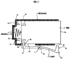
ここで操作者がロック部材3の操作部3dから指を離さずに操作部3dを保持していれば、図5に示すように、ロック部材3のヒンジ部3aよりロック爪3b側の部分を撓ませるようにして、ヒンジ部3aより凸部3c側の部分が反時計回り方向に回動し、凸部3cが電池2の先端部2cの側面2dに接触する。接触部を符号Bで示してある。なお、電池2の先端部2cが突き当て部6bから距離L2の位置に達したときに凸部3cが側面2dに接触し始める。この接触により、ロック部材3は図示した回動位置で時計回り方向に回動できないように拘束される。なお、このときのロック部材3の回動位置は、後述のように電池2が装着位置まで挿入されたときにロック爪3bが電池2の後端部2eに係合するのを可能とする回動位置である。これ以後は、電池2は先端部2cの側面2dが凸部3cに摺動して挿入される。
【0027】
なお、図5は、上記のように操作者が指を操作部3dから離さず図示の位置に保持している場合を示しており、この場合、ロック部材3のロック爪3bが電池2の後端部(取り出し方向側の端部)2eの側面2fから離れている。電池2の挿入開始から図5に示す位置への挿入までの間に操作者が指を操作部3dから離していれば、図5の時点でロック部材3のヒンジ部3aよりロック爪3b側の部分もロック爪3bが電池2の後端部2eの側面2fに接触するまで反時計方向に回動され、その後撓ませられる。
【0028】
さらに、電池2の先端部2cが電池収納部6の突き当て部6bに突き当たって位置決めされる装着位置まで挿入された後、操作者がロック部材3の操作部3dから指を離せば、撓んでいたロック部材3のヒンジ部3aよりロック爪3b側の部分が元の形状に復帰し、ロック爪3bが開口部6aに向かう方向に変位し、図2に示すように電池2の後端部2eの角部に係合し、電池2が装着位置に保持される。
【0029】
なお、これ以前に操作者が指を操作部3dから離していた場合は、電池2が装着位置まで挿入されたときに、それまで電池2の後端部2eの側面2fに接触していたロック爪3bが側面2fを乗り越えて開口部6aに向かう方向に変位し、図2のように、電池2の後端部2eの角部に係合し、電池2を装着位置に保持する。
【0030】
図2に示す電池2の装着位置への保持状態では、ロック部材3の凸部3cが電池2の先端部2cの側面2dに接触していることにより、ロック部材3が図示の回動位置から時計回り方向、すなわち電池2の後端部2eに対するロック爪3bの係合を解除する方向に対応する回動方向に回動できないように拘束されている。従って、操作者がロック部材3を指で撓ませてロック爪3bの係合を解除しない限り、ロック爪3bの係合は解除されず、電池2は電池収納部6内の装着位置に保持される。
【0031】
なお、この装着、保持状態において、電池2の給電端子2a,2bが電源端子1a,1bに接触して導通しており、電子機器への給電がなされることは勿論である。また、この装着、保持状態において、電池2に対するロック部材3のロック爪3bの係合による拘束力は、圧縮された電池押出しバネ4の復元力よりも大きいので、電池2が電池収納部6から離脱することが無く保持され、電子機器1への給電が維持、確保されることも勿論である。
【0032】
次に、電池2の取り出し動作を説明する。図2のように、電池2が電池収納部6内の装着位置に保持された状態から電池2を取り出す際には、操作者は先ずロック部材3の操作部3dに指を掛けて、図5に示すようにロック爪3b側が時計回り方向に撓むようにロック部材3を弾性変形させる。これにより電池2の後端部2eに対するロック爪3bの係合が解除され、電池2は圧縮されていた電池押出しバネ4の復元力の押圧により、電池取り出し方向で図中の右方向に移動する。電池2が取り出し方向に移動するに伴い、給電端子2a,2bと電源端子1a,1bの接触が解除され、電子機器1への駆動電源の供給が切断される。
【0033】
このとき、電池2の先端部2cが突き当て部6bの位置から距離L2の位置に達するまでは、ロック爪3b側が時計回り方向に撓むように弾性変形させられたロック部材3の凸部3cが電池2の先端部2cの側面2dに対してロック部材3の弾性力により圧接しており、両者の接触部Bにおいて電池2の取り出し方向に対して摩擦抵抗が働くが、この摩擦抵抗より電池押出しバネ4の復元力が大きくなるように設計されていることにより、電池2は摩擦抵抗に抗して取り出し方向に押し出されることとなる。
【0034】
ここで、電池押出しバネ4を円錐コイルバネとしている理由は、円錐コイルバネの荷重特性が圧縮量に対する復元力を非線形に設定することが可能だからである。本実施形態では、これを利用して、電池押出しバネ4の復元力、すなわち電池を押出す押出し力として、電池2の先端部2cが電池収納部6の突き当て部6bから距離L2の位置までの領域に位置する間は極めて強い押出し力が発揮され、距離L2の位置を越えて自由長L1の位置に至るまでの領域に位置する間は比較的低い押出し力が発揮されるように設計するものとする。
【0035】
こうすることにより、電池押出しバネ4の押出し力によって、電池2を上記の接触部Bの摩擦抵抗に抗して突き当て部6bから距離L2の位置よりも開口部6a側の位置で、図4に示すようにロック部材3の凸部3cと電池2の先端部2cの側面2dとの接触が解除された位置まで押出すことができる。
【0036】
但し通常の圧縮コイルバネを使用しても、同様にその押出し力によって電池2を上記接触が解除された位置まで押出すようにすることが実現できる。その際には、上記接触部Bでの摩擦抵抗を小さくするために、ロック部材3においてヒンジ部3aより凸部3c側の部分の変形に対する弾性力をロック爪3b側の部分の弾性力よりも小さくすれば良い。具体的には、ヒンジ部3aより凸部3c側の部分の腕の肉厚を薄くする、あるいは腕幅を狭くしたりすれば良い。
【0037】
さて、上記のように電池押出しバネ4の押出し力によって、図4に示すように、ロック部材3の凸部3cと電池2の先端部2cの側面2dとの接触が解除された位置まで電池2が押出されると、前記接触の解除により、ロック部材3は時計周り方向への回動が可能となる。このため、これまでロック爪3b側の部分が時計回り方向に撓ませられていたロック部材3は凸部3c側の部分が時計回り方向に回動して全体として元の形状に復帰する。したがって、この時点で操作者がロック部材3の操作部3dから指を離しても、ロック爪3b側の部分が弾性力で反時計方向に回動して電池2の後端部2eの側面2fに接触することはない。このため、電池2の取り出し方向に対する摩擦抵抗は発生せず、電池2をスムーズに電池収納部6から取り出すことが可能である。
【0038】
以上のような本実施形態によれば、電池2を電池収納部6に挿入して装着するときは、電池をその先端部2cがロック部材3の凸部3cに接触する位置(図4と図5の間で突き当て部6bに近い奥の位置)に挿入するまでは、操作者がロック部材3の操作部3dから指を離したとしても、凸部3cないしロック爪3bが電池2に接触することはなく、それによる摩擦抵抗は生じない。摩擦抵抗が生じるのは、上記の接触する位置以後で挿入ストロークの最後の短い一部分だけである。
【0039】
また、電池2を取り出すときは、電池2の先端部2cの側面2dとロック部材3の凸部3cが接触している間は、その接触による摩擦抵抗があるが、その摩擦抵抗に抗して電池押出しバネ4の押出し力で電池2が前記接触が解除された位置まで押し出される。そして、その後は、操作者がロック部材3の操作部3dから指を離したとしても、凸部3cないしロック爪3bが電池2に接触することはなく、それによる摩擦抵抗は生じない。
【0040】
したがって、本実施形態によれば、電池を挿入して装着する動作と取り出し動作をスムーズに行なうことができ、それぞれの動作における操作性が先述した従来例より格段に良くなる。また、先述した従来例のように、操作者が電池の取り出し又は挿入の途中でロック部材から指を離さないようにするために、ロック部材の変形ストロークを大きくするようなことが不要であり、電池収納部6の周辺寸法を小さくでき、電子機器の小型化を図れる。さらに、本実施形態の構造では、従来例に比べて部品点数が増えず、簡単で安価に実施することができる。
【0041】
[第2の実施形態]
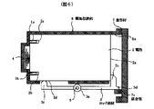
次に、本発明の第2の実施形態を図6により説明する。図6は、第2の実施形態における電子機器の電池収納部周辺の構造を示す断面図である。
【0042】
図6に示す本実施形態の構造では、上述した第1の実施形態と共通の電池収納部6周辺の構造に加えて、電池収納部6の開口部6aを開閉する蓋部材7が設けられている。蓋部材7は、不図示のヒンジにより電子機器の本体に対して開口部6aを開閉するように回動可能に取り付けられており、不図示のロック機構により、開口部6aを閉じた状態でロックできるようになっている。ロック機構は回転式ロック機構やスライド式ロック機構とする。
【0043】
蓋部材7の内側面には、ロック部材3の操作部3dと係合する係合部7aが設けられている。そして図示のように、電池収納部6内の装着位置に挿入された電池2の後端部2eにロック部材3のロック爪3bが係合して電池2が保持された状態であって、蓋部材7が閉じた状態で、係合部7aがロック部材3の操作部3dに係合することにより、ロック部材3のヒンジ部3aよりロック爪3b側の部分が図中で時計周り方向へ弾性変形し得ないように拘束する。すなわち、電池2の後端部2eに対するロック爪3bの係合を解除する方向へ弾性変形し得ないように拘束する。
【0044】
従って、この閉状態で蓋部材7を上記ロック機構によりロックしておけば、電子機器1が落下による衝撃等の外部からの衝撃を受けた際に、その衝撃で電池2の後端部2eに対するロック爪3bの係合が解除されてしまうことはなく、電池2が電池収納部6から飛び出してしまうことを確実に防止することができる。
【0045】
【発明の効果】
以上の説明から明らかなように、本発明によれば、駆動用電池を収納する電池収納部を有する電子機器において、電池収納部内の装着位置まで挿入された電池の後端部に係合して電池を装着位置に保持するロック部材に関わる構造を工夫することにより、従来に比べて部品点数が増えず、簡単で安価、しかも小型化が図れる構造で、電池を電池収納部へ挿入して装着する際と取り出す際の操作性を向上することができるという優れた効果が得られる。
【0046】
また、上記ロック部材に関連して、電池収納部の開口部を開閉する蓋部材の構造を工夫することにより、外部からの衝撃で電池が電池収納部から飛び出してしまうことを確実に防止することができ、電子機器の信頼性を向上できるという優れた効果が得られる。
【図面の簡単な説明】
【図1】本発明の第1の実施形態における電子機器の電池収納部を設けた手前側部分の外観を概略的に示す斜視図である。
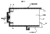
【図2】同電子機器の電池収納部に電池が装着された状態を示す電池収納部周辺の断面図である。
【図3】同電子機器の電池収納部に設けられた電池押出しバネの自由長とロック部材の凸部の位置との関係を示す電池収納部周辺の断面図である。
【図4】同電子機器の電池収納部に対する電池の挿入途中ないし取り出し途中で電池先端部の側面にロック部材の凸部が接触していない状態を示す電池収納部周辺の断面図である。
【図5】同電子機器の電池収納部に対する電池の挿入途中ないし取り出し途中で電池先端部の側面にロック部材の凸部が接触している状態を示す電池収納部周辺の断面図である。
【図6】本発明の第2の実施形態における電子機器の電池収納部周辺の構造を示す断面図である。
【図7】従来の電子機器の電池収納部に電池が装着された状態を示す電池収納部周辺の断面図である。
【図8】従来の電子機器の電池収納部に対する電池の挿入途中ないし取り出し途中でロック部材のロック爪が電池の後端部側面に接触している状態を示す電池収納部周辺の断面図である。
【符号の説明】
1 電子機器
2 電池
3 ロック部材
3a ヒンジ部
3b ロック爪
3c 凸部
3d 操作部
4 電池押出しバネ
5 ヒンジピン
6 電池収納部
7 蓋部材[0001]
TECHNICAL FIELD OF THE INVENTION
The present invention relates to an electronic device, and more particularly to an electronic device having a battery storage unit that stores a driving battery.
[0002]
[Prior art]
Conventionally, in this type of electronic device, in order to prevent a battery inserted and mounted in a battery housing from being pulled out, a lock member that is elastically deformable so as to bend is engaged with the battery to hold the battery. Such a structure is known from JP-A-10-241648 and the like. The structure is as shown in FIG. 7 and FIG. 8, and the
[0003]
When the operator mounts the
[0004]
When the
[0005]
[Problems to be solved by the invention]
However, the conventional structure as described above has the following problems.
[0006]
1) When the operator removes the
[0007]
2) Even when the
[0008]
3) As described above, when the deformation stroke of the
[0009]
Therefore, an object of the present invention is to provide an electronic device having a battery housing of this type with a structure that is simple, inexpensive, and can be miniaturized. It is to provide a structure that can be improved.
[0010]
[Means for Solving the Problems]
To solve the above problems, according to the present invention,
In electronic devices driven by batteries,
A battery housing section for housing the battery, the battery housing section having an opening formed on one end side for insertion and removal of the battery from the outside,
A lock member that engages with a rear end of the battery inserted to a predetermined mounting position in the battery housing and holds the battery in the mounting position, the lock member being elastically deformable in a direction in which the engagement is released. Has,
The lock member has a lock claw at one end engaging a rear end of the battery, a protrusion at the other end contacting a side surface of a front end of the battery, and a rotation fulcrum in the middle. With the part as a center of rotation, the unit is provided so as to be rotatable in a rotation direction corresponding to the direction in which the engagement is released and a rotation direction opposite thereto,
When the battery is inserted into and removed from the mounting position of the battery with respect to the battery storage portion, while the battery is in a region from a predetermined position close to the mounting position to the mounting position in the battery storage portion, the side surface of the tip portion of the battery has a convex portion of the lock member. By contacting the locking portion, the lock member is restrained from rotating in the rotation direction corresponding to the direction in which the lock is released in the rotation position allowing the engagement, whereby the battery is moved to the mounting position. A configuration is adopted in which the lock claw of the lock member can engage with the rear end of the battery when inserted.
[0011]
BEST MODE FOR CARRYING OUT THE INVENTION
Hereinafter, embodiments of the present invention will be described with reference to the drawings.
[0012]
[First Embodiment]
A structure for holding a battery in a battery storage section of an electronic device according to a first embodiment of the present invention will be described with reference to FIGS.
[0013]
First, FIG. 1 schematically illustrates an appearance of a front portion of the electronic device according to the present embodiment. The
[0014]
A battery housing 6 into which a battery 2 (see FIGS. 2 to 5) to be described later is inserted and mounted is provided on the front side of the
[0015]
Next, FIGS. 2 to 5 are cross-sectional views illustrating the structure around the battery housing portion 6 and the operations of inserting, mounting, and removing the battery. First, the structure will be described with reference to FIGS.
[0016]
In FIG. 2, it is assumed that the
[0017]
In the wall formed at the back of the battery storage section 6 in the battery insertion direction, a portion other than a central portion provided with a battery push-out
[0018]
On the other hand, a
[0019]
The
[0020]
The
[0021]
On the other hand, a battery push-out
[0022]
As shown in FIG. 3, the battery push-out
It is configured so that That is, the position of the leading end of the
L1-L2
It has been found that operability at the time of attaching and detaching the
[0023]
Next, mounting and removing operations of the battery will be described with reference to FIGS. First, the mounting operation will be described.
[0024]
When the
[0025]
When the
[0026]
Here, if the operator holds the
[0027]
FIG. 5 shows a case where the operator holds the finger at the illustrated position without releasing the finger from the
[0028]
Further, after the
[0029]
If the operator has separated his / her finger from the
[0030]
In the state where the
[0031]
In this mounting and holding state, the
[0032]
Next, the removal operation of the
[0033]
At this time, until the
[0034]
Here, the reason that the battery push-out
[0035]
By doing so, the
[0036]
However, even if a normal compression coil spring is used, it is possible to similarly push the
[0037]
By the pushing force of the
[0038]
According to the above-described embodiment, when the
[0039]
When the
[0040]
Therefore, according to the present embodiment, the operation of inserting and mounting the battery and the operation of taking out the battery can be performed smoothly, and the operability in each operation is much better than the above-described conventional example. Further, as in the above-described conventional example, it is unnecessary to increase the deformation stroke of the lock member so that the operator does not release his / her finger from the lock member during removal or insertion of the battery. The peripheral dimensions of the battery housing 6 can be reduced, and the size of the electronic device can be reduced. Further, in the structure of the present embodiment, the number of components is not increased as compared with the conventional example, and the structure can be implemented simply and inexpensively.
[0041]
[Second embodiment]
Next, a second embodiment of the present invention will be described with reference to FIG. FIG. 6 is a cross-sectional view illustrating a structure around a battery storage unit of an electronic device according to the second embodiment.
[0042]
In the structure of the present embodiment shown in FIG. 6, a lid member 7 for opening and closing the
[0043]
An engagement portion 7a that engages with the
[0044]
Therefore, if the lid member 7 is locked by the lock mechanism in the closed state, when the
[0045]
【The invention's effect】
As is apparent from the above description, according to the present invention, in an electronic device having a battery storage portion for storing a driving battery, the electronic device is engaged with a rear end portion of the battery inserted to a mounting position in the battery storage portion. By devising the structure related to the lock member that holds the battery in the mounting position, the number of parts does not increase compared to the conventional, the structure is simple, inexpensive, and it can be downsized, and the battery is inserted into the battery storage and mounted An excellent effect is obtained that the operability when performing and taking out can be improved.
[0046]
In addition, in connection with the lock member, by devising the structure of the lid member that opens and closes the opening of the battery housing, it is possible to reliably prevent the battery from jumping out of the battery housing due to an external impact. And an excellent effect of improving the reliability of the electronic device can be obtained.
[Brief description of the drawings]
FIG. 1 is a perspective view schematically showing an appearance of a front side portion provided with a battery housing portion of an electronic device according to a first embodiment of the present invention.
FIG. 2 is a cross-sectional view of the vicinity of the battery storage unit showing a state where a battery is mounted in the battery storage unit of the electronic device.
FIG. 3 is a cross-sectional view of the periphery of the battery housing showing a relationship between a free length of a battery push spring provided in the battery housing of the electronic device and a position of a convex portion of a lock member.
FIG. 4 is a cross-sectional view of the vicinity of the battery housing showing a state in which the protrusion of the lock member does not contact the side surface of the battery tip during the insertion or removal of the battery into or from the battery housing of the electronic device.
FIG. 5 is a cross-sectional view of the vicinity of the battery housing showing a state in which the protrusion of the lock member is in contact with the side surface of the battery tip during the insertion or removal of the battery into or from the battery housing of the electronic device.
FIG. 6 is a cross-sectional view illustrating a structure around a battery housing portion of an electronic device according to a second embodiment of the present invention.
FIG. 7 is a cross-sectional view of the periphery of a battery storage unit showing a state where a battery is mounted in the battery storage unit of a conventional electronic device.
FIG. 8 is a cross-sectional view of the periphery of the battery housing showing a state in which a lock claw of a lock member is in contact with a side surface of a rear end of the battery during insertion or removal of the battery into or from the battery housing of a conventional electronic device. .
[Explanation of symbols]
DESCRIPTION OF
Claims (3)
前記電池を収納する電池収納部であって、一端側に前記電池の外部からの挿入と外部への取り出しを行うための開口部が形成された電池収納部と、
該電池収納部内の所定の装着位置まで挿入された電池の後端部に係合して電池を装着位置に保持するロック部材であって、前記係合を解除する方向に弾性変形可能なロック部材を有し、
該ロック部材は、一端に前記電池の後端部に係合するロック爪、他端に前記電池の前端部の側面に接触する凸部、中間に回動支点部が形成され、該回動支点部を回動中心として、前記係合を解除する方向に対応する回動方向とその逆の回動方向に回動可能に設けられており、
前記電池収納部に対する電池の装着位置への挿入及び取り出し時に、電池が電池収納部内で装着位置に近い所定位置から装着位置までの領域にある間は、電池の先端部側面が前記ロック部材の凸部に接触することにより、ロック部材が前記係合を可能とする回動位置で前記係合を解除する方向に対応する回動方向に回動できないように拘束され、それにより電池が装着位置まで挿入されたときにロック部材のロック爪が電池の後端部に係合し得るようにしたことを特徴とする電子機器。In electronic devices driven by batteries,
A battery housing section for housing the battery, the battery housing section having an opening formed on one end side for insertion and removal of the battery from the outside,
A lock member that engages with a rear end of the battery inserted to a predetermined mounting position in the battery housing and holds the battery in the mounting position, the lock member being elastically deformable in a direction in which the engagement is released. Has,
The lock member has a lock claw at one end engaging a rear end of the battery, a protrusion at the other end contacting a side surface of a front end of the battery, and a rotation fulcrum in the middle. With the part as a center of rotation, the unit is provided so as to be rotatable in a rotation direction corresponding to the direction in which the engagement is released and a rotation direction opposite thereto,
When the battery is inserted into and removed from the mounting position of the battery with respect to the battery storage portion, while the battery is in a region from a predetermined position close to the mounting position to the mounting position in the battery storage portion, the side surface of the tip portion of the battery has a convex portion of the lock member. By contacting the locking portion, the lock member is restrained from rotating in the rotation direction corresponding to the direction in which the lock is released in the rotation position allowing the engagement, whereby the battery is moved to the mounting position. An electronic device wherein a lock claw of a lock member can be engaged with a rear end of a battery when inserted.
Priority Applications (1)
| Application Number | Priority Date | Filing Date | Title |
|---|---|---|---|
| JP2002166428A JP4005418B2 (en) | 2002-06-07 | 2002-06-07 | Electronics |
Applications Claiming Priority (1)
| Application Number | Priority Date | Filing Date | Title |
|---|---|---|---|
| JP2002166428A JP4005418B2 (en) | 2002-06-07 | 2002-06-07 | Electronics |
Publications (2)
| Publication Number | Publication Date |
|---|---|
| JP2004014308A true JP2004014308A (en) | 2004-01-15 |
| JP4005418B2 JP4005418B2 (en) | 2007-11-07 |
Family
ID=30433974
Family Applications (1)
| Application Number | Title | Priority Date | Filing Date |
|---|---|---|---|
| JP2002166428A Expired - Fee Related JP4005418B2 (en) | 2002-06-07 | 2002-06-07 | Electronics |
Country Status (1)
| Country | Link |
|---|---|
| JP (1) | JP4005418B2 (en) |
Cited By (4)
| Publication number | Priority date | Publication date | Assignee | Title |
|---|---|---|---|---|
| JP2005285713A (en) * | 2004-03-31 | 2005-10-13 | Sharp Corp | Battery attachment / detachment device |
| CN106910862A (en) * | 2017-02-28 | 2017-06-30 | 长沙安靠电源有限公司 | Plug-in type battery connecting apparatus |
| CN111765107A (en) * | 2020-06-24 | 2020-10-13 | 河南驼人贝斯特医疗器械有限公司 | A new type of air supply device |
| WO2021258816A1 (en) * | 2020-06-24 | 2021-12-30 | 河南驼人贝斯特医疗器械有限公司 | Protective suit having air supply device |
Families Citing this family (1)
| Publication number | Priority date | Publication date | Assignee | Title |
|---|---|---|---|---|
| CN113036289B (en) * | 2021-03-04 | 2022-06-28 | 广东力王新能源股份有限公司 | Direct-insertion type Bluetooth battery convenient to replace |
-
2002
- 2002-06-07 JP JP2002166428A patent/JP4005418B2/en not_active Expired - Fee Related
Cited By (6)
| Publication number | Priority date | Publication date | Assignee | Title |
|---|---|---|---|---|
| JP2005285713A (en) * | 2004-03-31 | 2005-10-13 | Sharp Corp | Battery attachment / detachment device |
| CN106910862A (en) * | 2017-02-28 | 2017-06-30 | 长沙安靠电源有限公司 | Plug-in type battery connecting apparatus |
| CN111765107A (en) * | 2020-06-24 | 2020-10-13 | 河南驼人贝斯特医疗器械有限公司 | A new type of air supply device |
| WO2021258816A1 (en) * | 2020-06-24 | 2021-12-30 | 河南驼人贝斯特医疗器械有限公司 | Protective suit having air supply device |
| KR20230016693A (en) * | 2020-06-24 | 2023-02-02 | 허난 투오런 베스트 메디컬 디바이스 컴퍼니 리미티드 | hazmat suit with some kind of ventilation device |
| KR102817996B1 (en) * | 2020-06-24 | 2025-06-05 | 허난 투오런 베스트 메디컬 디바이스 컴퍼니 리미티드 | A protective suit with some sort of ventilation device |
Also Published As
| Publication number | Publication date |
|---|---|
| JP4005418B2 (en) | 2007-11-07 |
Similar Documents
| Publication | Publication Date | Title |
|---|---|---|
| CN100479253C (en) | Battery pack | |
| JP3729696B2 (en) | IC card connector | |
| US8622646B2 (en) | Electronic device with slot cover ejection mechanism | |
| US8437814B2 (en) | Slide opening/closing device, method of restricting sliding movement of slide member, electronic apparatus, and mobile terminal device | |
| US7804683B2 (en) | Electronic device component eject mechanism | |
| JP2003217738A (en) | Card connector | |
| US7430115B2 (en) | Apparatus for mounting removably a disk drive in an electronic device | |
| US6796816B2 (en) | Card connector having strengthened ejection mechanism | |
| TWI536684B (en) | Card connector | |
| US8264845B2 (en) | Electronic device with cover ejection mechanism | |
| JP2004014308A (en) | Electronic apparatus | |
| CN101472411A (en) | Cover-turning type electronic device casing | |
| EP1691430A2 (en) | Electronic instrument | |
| JP2001097422A (en) | Lid opening and closing device | |
| TWI290783B (en) | Connector which can be reduced in size | |
| JP3662861B2 (en) | Mobile terminal device with memory card | |
| JP2009070608A (en) | Electronic equipment | |
| JPH07105325A (en) | Card-type storage medium connector | |
| JP3560785B2 (en) | Battery storage device | |
| JP2004014456A (en) | Connector device for cards | |
| JP5782475B2 (en) | Device container | |
| JP4190350B2 (en) | Mounting mechanism, electronic equipment, external device | |
| JP2000268792A (en) | Battery device housing structure for electronic equipment | |
| JP2791854B2 (en) | Card connector with eject mechanism | |
| JP2003142205A (en) | Card connector |
Legal Events
| Date | Code | Title | Description |
|---|---|---|---|
| A621 | Written request for application examination |
Free format text: JAPANESE INTERMEDIATE CODE: A621 Effective date: 20050526 |
|
| RD03 | Notification of appointment of power of attorney |
Free format text: JAPANESE INTERMEDIATE CODE: A7423 Effective date: 20070221 |
|
| A977 | Report on retrieval |
Free format text: JAPANESE INTERMEDIATE CODE: A971007 Effective date: 20070226 |
|
| RD04 | Notification of resignation of power of attorney |
Free format text: JAPANESE INTERMEDIATE CODE: A7424 Effective date: 20070309 |
|
| A131 | Notification of reasons for refusal |
Free format text: JAPANESE INTERMEDIATE CODE: A131 Effective date: 20070413 |
|
| A521 | Request for written amendment filed |
Free format text: JAPANESE INTERMEDIATE CODE: A523 Effective date: 20070607 |
|
| TRDD | Decision of grant or rejection written | ||
| A01 | Written decision to grant a patent or to grant a registration (utility model) |
Free format text: JAPANESE INTERMEDIATE CODE: A01 Effective date: 20070727 |
|
| A61 | First payment of annual fees (during grant procedure) |
Free format text: JAPANESE INTERMEDIATE CODE: A61 Effective date: 20070823 |
|
| R150 | Certificate of patent or registration of utility model |
Free format text: JAPANESE INTERMEDIATE CODE: R150 |
|
| FPAY | Renewal fee payment (event date is renewal date of database) |
Free format text: PAYMENT UNTIL: 20100831 Year of fee payment: 3 |
|
| FPAY | Renewal fee payment (event date is renewal date of database) |
Free format text: PAYMENT UNTIL: 20110831 Year of fee payment: 4 |
|
| FPAY | Renewal fee payment (event date is renewal date of database) |
Free format text: PAYMENT UNTIL: 20110831 Year of fee payment: 4 |
|
| FPAY | Renewal fee payment (event date is renewal date of database) |
Free format text: PAYMENT UNTIL: 20120831 Year of fee payment: 5 |
|
| FPAY | Renewal fee payment (event date is renewal date of database) |
Free format text: PAYMENT UNTIL: 20120831 Year of fee payment: 5 |
|
| FPAY | Renewal fee payment (event date is renewal date of database) |
Free format text: PAYMENT UNTIL: 20130831 Year of fee payment: 6 |
|
| R250 | Receipt of annual fees |
Free format text: JAPANESE INTERMEDIATE CODE: R250 |
|
| R250 | Receipt of annual fees |
Free format text: JAPANESE INTERMEDIATE CODE: R250 |
|
| LAPS | Cancellation because of no payment of annual fees |