JP2004018024A - Built-in stopper with tamper-evident opening blade - Google Patents
Built-in stopper with tamper-evident opening blade Download PDFInfo
- Publication number
- JP2004018024A JP2004018024A JP2002175370A JP2002175370A JP2004018024A JP 2004018024 A JP2004018024 A JP 2004018024A JP 2002175370 A JP2002175370 A JP 2002175370A JP 2002175370 A JP2002175370 A JP 2002175370A JP 2004018024 A JP2004018024 A JP 2004018024A
- Authority
- JP
- Japan
- Prior art keywords
- cap
- spout
- occlusal
- ring
- tamper
- Prior art date
- Legal status (The legal status is an assumption and is not a legal conclusion. Google has not performed a legal analysis and makes no representation as to the accuracy of the status listed.)
- Pending
Links
Images

Landscapes
- Cartons (AREA)
- Closures For Containers (AREA)
Abstract
【課題】キャップを螺脱するときに、周壁と不正開封防止環を接続する薄肉脆弱ブリッジが確実に切断されやすく、キャップから分離した不正開封防止環が浮いたまま残ることがない不正開封防止付開封刃内蔵口栓を提供する。
【解決手段】開封用筒体300 を内蔵するスパウト100 と不正開封防止環230 が周壁下端に薄肉脆弱ブリッジ222 で接続するキャップ200 からなり、キャップの螺脱時に、薄肉脆弱ブリッジが破断されて不正開封防止環がキャップから分離し、スパウトに内蔵する下端に開封刃をもつ開封用筒体が降下して、封止フィルムを破断して容器を開封し、キャップの不正開封防止環の下端部内周面に等間隔で周方向へ複数個の咬合突部231 を設け、スパウトの注出筒の下方に設ける咬合リング112 下に、不正開封防止環の咬合突部間よりも幅狭の係止突部113 を咬合突部間に挿入可能に周方向へ複数個設ける。
【選択図】図1A thin fragile bridge connecting a peripheral wall and a tamper-evident ring is easily cut off when the cap is unscrewed, and the tamper-proof ring separated from the cap does not remain floating. Provide a plug with a built-in opening blade.
A spout with a built-in opening cylinder and a tamper-evident ring are formed of a cap connected to a lower end of a peripheral wall with a thin brittle bridge. The opening prevention ring separates from the cap, the opening cylinder having an opening blade at the lower end built into the spout descends, breaks the sealing film and opens the container, and the inner circumference of the lower end of the cap unauthorized opening prevention ring. A plurality of occlusal protruding portions 231 are provided at equal intervals in the circumferential direction on the surface, and a locking protruding portion narrower than the occlusal protruding portion of the tamper-evident ring is provided below the occlusal ring 112 provided below the spout discharge tube. A plurality of portions 113 are provided in the circumferential direction so as to be inserted between the occlusal projections.
[Selection diagram] Fig. 1
Description
【0001】
【発明の属する技術分野】
本発明は、清酒、果汁飲料、調味料、柔軟剤や液体洗剤などに使用される液体用紙容器の頂部に突設される不正開封防止付開封刃内蔵口栓に関するものである。
【0002】
【従来の技術】
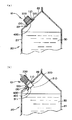
従来、液体用紙容器(20)には、例えば図4(a)に示すように、四角柱状の胴部(21)をもち、その切妻屋根形の頂部傾斜板(22)には、注出のし易さから開封刃内蔵口栓(10)が突設されたものが広い商品分野において使用されてきた。この開封刃内蔵口栓(10)には、図4(b)に示すように、下端に複数の三角状の開封刃(310)を欠刃部(311)を設けて並設した開封用筒体(300)をスパウト(100)(注出口具)の注出筒(110)内側に下降可能に内蔵し、スパウトに螺着したキャップ(200)を螺脱方向へ回転させたときに、キャップの天板の中央位置に垂設されたガイド用内筒の外周面に設けられた螺旋状の摺接案内傾斜面と、開封用筒体の内周面に設けられた螺旋状の摺接案内傾斜面との摺接によって、開封用筒体(300)を降下させ、この開封用筒体の下端に設けられた開封刃(310)で液体用紙容器を封止する封止フィルム(400)を破断して開口するものが知られていた。また、図3に示すように、上述のキャップ(200)の周壁(220)の下端に薄肉脆弱ブリッジ(222)を介して下端部内周面に複数個の咬合突部(231)を周方向に設けた不正開封防止環(230)を接続し、スパウト(100)の注出筒(110)の下方にキャップの咬合突部(231)と咬合する咬合リング(112)を設けて、不正に容器を開封しようとしてキャップを螺脱方向へ回転すると、薄肉脆弱ブリッジが切断されて不正開封防止環がキャップから分離し、不正に開封されたことが判明する不正開封防止付開封刃内蔵口栓(10)が知られていた。なお、図4(b)に示す開封用筒体(300)の下端に欠刃部(311)を設けて開封刃(310)を並設するのは、封止フィルムの破断片(401)が内容物(30)中に落下しないようにするためである。そして、この開封刃内蔵口栓には、スパウトの下面に封止フィルムを熱融着して注出筒の下部開口部を封止した口栓を、液体用紙容器の口栓取付孔に注出筒を突出させて、フランジの上面を容器の内面に熱融着して取り付ける内付けのものと、図6(a)に示すように、液体用紙容器(20)の封止フィルム(400)で封止した注出孔(23)の外周縁部上面に、スパウト(100)のフランジ(120)の下面を熱融着して取り付ける外付けのものとがある。
【0003】
【発明が解決しようとする課題】
ところで、上述の従来の不正開封防止付開封刃内蔵口栓においては、キャップを螺脱方向へ回転して、キャップを上昇させたときに、キャップの不正開封防止環の咬合突部の上面がスパウトの咬合リングの下面に当接して、キャップの上昇力によってキャップの周壁と不正開封防止環を接続する薄肉脆弱ブリッジが切断されるものであるが、キャップをスパウトに螺着しやすくするために、キャップの不正開封防止環の咬合突部とスパウトの咬合リングとの嵌合代を小さくすると、不正開封防止環の咬合突部がスパウトの咬合リング上に乗り上げて、薄肉脆弱ブリッジが切断されても切断後に不正開封防止環が浮いたまま残ったり、また、薄肉脆弱ブリッジが切断されにくいことなどがあった。
【0004】
本発明は、上述の従来の不正開封防止付開封刃内蔵口栓の問題を解決したものであり、キャップを螺脱方向へ回転したときに、周壁と不正開封防止環を接続する薄肉脆弱ブリッジが確実に切断されやすく、また、キャップと分離した不正開封防止環が浮いたまま残ることがない不正開封防止付開封刃内蔵口栓を提供するものである。
【0005】
【課題を解決するための手段】
すなわち、本発明の第1の発明は、液体用紙容器の注出位置に突設され、開封用筒体を内蔵するスパウトと、不正開封防止環が周壁の下端に薄肉脆弱ブリッジを介して接続し前記スパウトに螺着するキャップとからなり、前記キャップを螺脱方向へ回転させたときに、前記薄肉脆弱ブリッジが破断されて前記不正開封防止環が前記キャップから分離し、前記スパウトの注出筒内側に内蔵され下端に開封刃をもつ開封用筒体が、前記キャップの螺脱方向への回転にともなって降下して、下方に設けられている封止フィルムを破断して容器を開封する口栓において、前記キャップの不正開封防止環の下端部内周面に等間隔で周方向へ複数個の咬合突部を設け、前記スパウトの注出筒の下方に設ける咬合リング下に、前記キャップの不正開封防止環の咬合突部間よりも幅狭の係止突部を前記咬合突部間に挿入可能に等間隔で周方向へ複数個設けたことを特徴とする不正開封防止付開封刃内蔵口栓である。
【0006】
次に、本発明の第2の発明は、前記キャップの咬合突部と前記スパウトの咬合リングとの嵌合代を、径寸法で0.6〜1.4mmにしたことを特徴とする第1の発明に記載の不正開封防止付開封刃内蔵口栓である。
【0007】
次に、本発明の第3の発明は、前記キャップの咬合突部の両端を水平断面が直線状の垂直面に形成し、前記スパウトの係止突部の前記キャップの螺着時に前記キャップの咬合突部と当接する側を水平断面が円弧状の垂直面に形成し、前記キャップの螺脱時に前記キャップの咬合突部と当接する側を水平断面が直線状の垂直面に形成したことを特徴とする第1又は第2の発明に記載の不正開封防止付開封刃内蔵口栓である。
【0008】
そして、本発明の第4の発明は、前記スパウトの係止突部の垂直方向の長さを、前記キャップの咬合突部の上面と前記スパウトの咬合リングの下面との隙間の±0.3mmにしたことを特徴とする第1乃至第3の発明に記載の不正開封防止付開封刃内蔵口栓である。
【0009】
【発明の実施の形態】
次に、本発明の不正開封防止付開封刃内蔵口栓の実施の形態について、図を用いて詳細に説明する。
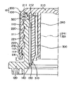
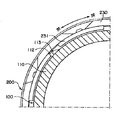
図1は、本発明の一実施形態の不正開封防止付開封刃内蔵口栓の断面図であり、図2は、キャップの不正防止環に設ける咬合突部及びスパウトの注出筒の咬合リング下に設ける係止突部の形状を示すA−A’断面図である。
【0010】
本発明の一実施形態の不正開封防止付開封刃内蔵口栓(10)は、図1に示すように、下端に開封刃(310)をもつ開封用筒体(300)を移動可能に内蔵するスパウト(100)とこのスパウトに螺着するキャップ(200)とからなり、キャップは、周壁(220)下端に複数の薄肉脆弱ブリッジ(223)を介して下端内周面に咬合突部(231)をもつ不正開封防止環(230)を接続し、天板(210)下面中央部に開封用筒体を下降させる相対向する通常2個の摺接案内傾斜面(241)を周方向へ等間隔で外周面に設けたガイド用内筒(240)を垂設し、また、天板(210)下面には必要に応じた、例えばコンタクト封止リング(211)やインナー封止リング(212)などの封止リングを設け、周壁(220)の内周面には、螺合部(221)を形成するものである。そして、開封用筒体(300)は、キャップの摺接案内傾斜面(241)に対応させて2個の摺接案内傾斜面(301)を周方向へ等間隔で内周面に設け、外周面上端部に通常4個の摺動突起(320)を周方向へ等間隔に設け、スパウト(100)は、注出筒(110)の内周面に、開封用筒体の摺動突起に対応させた通常8個の摺接縦リブ(130)を周方向へ等間隔に設け、外周面の螺合部(111)の下方に、キャップの不正開封防止環の咬合突部(231)が咬合する咬合リング(112)を設けるものである。そして、図1及び図2に示すように、キャップ(200)の不正開封防止環(230)の下端部内周面に等間隔で周方向へ通常8個の咬合突部(231)を設け、スパウト(100)の注出筒(110)の下方に設ける咬合リング(112)下に、キャップの不正開封防止環の咬合突部間よりも幅狭の係止突部(113)を、咬合突部間に挿入可能に等間隔で周方向へ通常2個又は4個設けるものである。
【0011】
上述のキャップの咬合突部とスパウトの咬合リングとの嵌合代は、径寸法で0.6〜1.4mmにするものである。0.6mmより小さい場合には、薄肉脆弱ブリッジが破断されずにキャップの咬合突部がスパウトの咬合リングを乗り越えてしまいことがあり、1.4mmより大きい場合には、キャップをスパウトに螺着するきに、キャップの咬合突部がスパウトの咬合リングを乗り越えることができないことがある。
【0012】
また、図2に示すように、キャップ(200)の不正開封防止環(230)の下端部内周面に設ける咬合突部(231)の形状は、両端を水平断面が直線状の垂直面に形成するものである。また、スパウト(100)の注出筒(110)の外周面の咬合リング(112)下に設ける係止突部(113)の形状は、キャップの螺着時(矢印左側)にキャップの咬合突部と当接する側を水平断面が円弧状の垂直面に形成し、キャップの螺脱時(矢印右側)にキャップの咬合突部と当接する側を水平断面が直線状の垂直面に形成するものである。
【0013】
また、図1に示すように、スパウト(100)の係止突部(113)の垂直方向の長さは、キャップ(200)の咬合突部(231)の上面とスパウトの咬合リング(112)の下面との隙間の±0.3mmにするものである。0.3mm以上大きくした場合には、キャップをスパウトに螺着するときの抵抗が大きくなり、0.3mm以上小さい場合には、キャップをスパウトから螺脱するときに、係止突部の不正開封防止環に対する係止効果が小さくなり、薄肉脆弱ブリッジの確実な破断がしにくくなる。
【0014】
液体用紙容器の頂部に取り付けられた未開封の本実施形態の不正開封防止付開封刃内蔵口栓は、キャップを螺脱方向へ回転させると、キャップが上昇しながら、キャップの不正開封防止環の下端内周面に設けられている咬合突部の片側面が容器に固着するスパウトの咬合リング下に設けられている係止突部の片側面に当接し、不正開封防止環が係止状態になる。このため、さらにキャップを螺脱方向へ回転させると、キャップの周壁と不正開封防止環とを接続している薄肉脆弱ブリッジが、キャップの回転力と上昇力とにより切断される。このとき、キャップの不正開封防止環の咬合突部のスパウトの係止突部と当接する面は、水平断面が直線状の垂直面であり、また、スパウトの係止突部のキャップの不正開封防止環の咬合突部と当接する面は、水平断面が直線状の垂直面でるため、不正開封防止環の係止が確実に行われ、従って、キャップの薄肉脆弱ブリッジの切断も確実に行われる。また、不正開封防止環の咬合突部がスパウトの咬合リング上に乗り上げて浮いた状態になることがない。
【0015】
なお、スパウトの注出筒にキャップを螺着方向へ回転させて装着するときは、キャップの不正開封防止環の下端内周面に設けられている咬合突部の片側面が スパウトの咬合リング下に設けられている係止突部に当接しても、スパウトの係止突部のキャップの咬合突部と当接する面が、水平断面が円弧状の垂直面であるため、キャップの咬合突部のスパウトの係止突部と当接する面が水平断面が直線状の垂直面であっても、キャップの咬合突部がスパウトの係止突部を容易に乗り越えることができる。
【0016】
【発明の効果】
本発明の不正開封防止付開封刃内蔵口栓は、スパウトの注出筒の下方に設ける咬合リング下に、キャップの不正開封防止環の咬合突部間よりも幅狭の係止突部をスパウトの咬合突部間に挿入可能に複数個設てあり、キャップを螺脱方向へ回転したときに、周壁と不正開封防止環を接続する薄肉脆弱ブリッジが確実に切断されやすく、また、キャップと分離した不正開封防止環が浮いたまま残ることがない。
【図面の簡単な説明】
【図1】本発明の一実施形態の不正開封防止付開封刃内蔵口栓の断面図である。
【図2】本発明の一実施形態の不正開封防止付開封刃内蔵口栓のキャップの不正防止環に設ける咬合突部及びスパウトの注出筒の咬合リング下に設ける係止突部の形状を示すA−A’断面図である。
【図3】従来の一例の不正開封防止付開封刃内蔵口栓の断面図である。
【図4】(a)は、一例の開封刃内蔵口栓を取り付けた液体用紙容器の開封前の状態を示す説明図であり、(b)は、開封したときの状態を示すを示すA−A’断面図である。
【符号の説明】
10……開封刃内蔵口栓
20……液体用紙容器
21……胴部
22……頂部傾斜板
23……注出孔
30……内容物
100……スパウト
110……注出筒
111,221……螺合部
112……咬合リング
113……係止突部
120……フランジ
130……摺接縦リブ
140……摺接溝
200……キャップ
210……天板
211……コンタクト封止リング
212……インナー封止リング
220……周壁
222……薄肉脆弱ブリッジ
230……不正開封防止環
231……咬合突部
240……ガイド用内筒
241,301……摺接案内傾斜面
300……開封用筒体
310……開封刃
311……欠刃部
320……摺動突起
400……封止フィルム
401……破断片[0001]
TECHNICAL FIELD OF THE INVENTION
The present invention relates to a stopper with a built-in anti-tampering opening blade protruding from the top of a liquid paper container used for sake, fruit drinks, seasonings, softeners, liquid detergents and the like.
[0002]
[Prior art]
Conventionally, a liquid paper container (20) has, for example, as shown in FIG. 4 (a), a quadrangular prism-shaped body (21), and a gable roof-shaped top inclined plate (22) has a spout. For ease of operation, the one provided with the opening plug (10) with a built-in opening blade has been used in a wide range of commercial fields. As shown in FIG. 4B, the opening plug with built-in opening blade (10) is provided with a plurality of triangular opening blades (310) at the lower end thereof and an opening tube provided with a cut-off portion (311). The body (300) is built inside the spout cylinder (110) of the spout (100) (spout device) so as to be able to descend, and when the cap (200) screwed to the spout is rotated in the unscrewing direction, the cap Spiral sliding guide inclined surface provided on the outer peripheral surface of the guide inner cylinder vertically suspended at the center position of the top plate, and spiral sliding contact guide provided on the inner peripheral surface of the opening tubular body The opening cylinder (300) is lowered by sliding contact with the inclined surface, and the sealing film (400) for sealing the liquid paper container with the opening blade (310) provided at the lower end of the opening cylinder. It has been known that it breaks and opens. As shown in FIG. 3, a plurality of occlusal projections (231) are circumferentially formed on the inner peripheral surface of the lower end via a thin brittle bridge (222) at the lower end of the peripheral wall (220) of the cap (200). The tamper-evident ring (230) provided is connected, and an occlusal ring (112) is provided below the spout (110) of the spout (100) to engage with the occlusal projection (231) of the cap. When the cap is rotated in the unscrewing direction to open the cap, the thin fragile bridge is cut off, the tamper-evident ring is separated from the cap, and it is found that the tamper-evident opening has been completed. ) Was known. The reason why the opening blade (310) is provided in parallel with the opening blade (310) provided at the lower end of the opening cylinder (300) shown in FIG. This is so as not to fall into the contents (30). Then, into the opening blade built-in plug, a sealing film is heat-sealed on the lower surface of the spout to seal the lower opening of the dispensing cylinder, and the stopper is poured into the stopper mounting hole of the liquid paper container. 6A, the cylinder is projected and the upper surface of the flange is heat-sealed to the inner surface of the container, and the sealing film (400) of the liquid paper container (20) as shown in FIG. On the upper surface of the outer periphery of the sealed pouring hole (23), there is an external one which is attached by heat-sealing the lower surface of the flange (120) of the spout (100).
[0003]
[Problems to be solved by the invention]
By the way, in the above-mentioned conventional plug with a built-in opening blade with tamper-proof, when the cap is rotated in the unscrewing direction and the cap is raised, the upper surface of the occlusal projection of the tamper-proof ring of the cap is spouted. Abutting against the lower surface of the occlusal ring, the thin fragile bridge that connects the peripheral wall of the cap and the tamper-evident ring is cut off by the lifting force of the cap, but in order to easily screw the cap onto the spout, If the margin of engagement between the occlusal projection of the cap tamper-evident ring and the occlusal ring of the spout is reduced, even if the occlusal projection of the tamper-evident ring rides on the occlusal ring of the spout, the thin brittle bridge is cut After cutting, the tamper-evident ring was left floating, and the thin-walled fragile bridge was difficult to cut.
[0004]
The present invention solves the above-mentioned problem of the conventional tamper-evident opening cap with built-in opening blade.When the cap is rotated in the unscrewing direction, a thin fragile bridge connecting the peripheral wall and the tamper-evident ring is provided. An object of the present invention is to provide a plug with a built-in tamper-proof opening blade that is easy to be surely cut and does not leave a tamper-evident ring separated from a cap floating.
[0005]
[Means for Solving the Problems]
That is, the first invention of the present invention is characterized in that the spout protrudingly provided at the discharge position of the liquid paper container and having a built-in opening cylinder is connected to the lower end of the peripheral wall through a thin brittle bridge at the lower end of the peripheral wall. The cap is screwed onto the spout, and when the cap is rotated in the unscrewing direction, the thin-walled fragile bridge is broken and the tamper-evident ring is separated from the cap, and the spout ejection tube An opening tube that is built in and has an opening blade at the lower end, which lowers with the rotation of the cap in the unscrew direction, breaks the sealing film provided below, and opens the container. In the stopper, a plurality of occlusal projections are provided in the circumferential direction at equal intervals on the inner peripheral surface of the lower end portion of the tamper-evident prevention ring of the cap, and under the occlusal ring provided below the spout discharge cylinder, the cap is tampered with. Opening prevention ring A tamper evident with open blades built spout that is characterized by providing a plurality in insertably equidistant narrow of the locking projection between the occlusal projection in the circumferential direction than the inter-occlusal projection.
[0006]
Next, a second invention of the present invention is characterized in that the fitting margin between the occlusal projection of the cap and the occlusal ring of the spout is set to a diameter of 0.6 to 1.4 mm. The invention is a plug with a built-in unsealing blade with tamper-proofing.
[0007]
Next, the third invention of the present invention is characterized in that both ends of the occlusal projection of the cap are formed in a vertical surface having a horizontal cross section in a straight line, and the cap of the cap is screwed into the locking projection of the spout when the cap is screwed. The side in contact with the occlusal projection has a horizontal section formed in a vertical arc-shaped surface, and the side in contact with the occlusal projection of the cap when the cap is unscrewed has a horizontal section formed in a linear vertical plane. A plug with a built-in unsealing blade according to the first or second aspect of the invention.
[0008]
The fourth invention of the present invention is characterized in that the vertical length of the locking projection of the spout is set to ± 0.3 mm of the gap between the upper surface of the occlusal projection of the cap and the lower surface of the occlusal ring of the spout. The opening plug with a built-in unsealing blade according to any one of the first to third inventions, wherein
[0009]
BEST MODE FOR CARRYING OUT THE INVENTION
Next, an embodiment of a plug with a built-in unsealing blade according to the present invention will be described in detail with reference to the drawings.
FIG. 1 is a cross-sectional view of a plug with a built-in unsealing blade with tamper-proof according to one embodiment of the present invention. FIG. FIG. 4 is a cross-sectional view taken along the line AA ′ showing the shape of a locking projection provided in FIG.
[0010]
As shown in FIG. 1, the tamper-resistant opening plug with built-in opening blade (10) of the embodiment of the present invention movably incorporates an opening cylinder (300) having an opening blade (310) at the lower end. It comprises a spout (100) and a cap (200) screwed to the spout, and the cap is provided on a lower end inner peripheral surface through a plurality of thin brittle bridges (223) at the lower end of the peripheral wall (220). A tamper-evident ring (230) having a slash is connected, and two opposing sliding contact guide inclined surfaces (241) for lowering the opening cylinder at the center of the lower surface of the top plate (210) are equally spaced in the circumferential direction. A guide inner cylinder (240) provided on the outer peripheral surface is vertically provided, and a contact sealing ring (211), an inner sealing ring (212), and the like are provided on the lower surface of the top plate (210) as necessary. Of the peripheral wall (220) is provided. On the surface, it is to form threaded portion (221). The opening cylindrical body (300) is provided with two sliding guide inclined surfaces (301) on the inner peripheral surface at equal intervals in the circumferential direction so as to correspond to the sliding contact inclined surfaces (241) of the cap. Usually, four sliding protrusions (320) are provided at the upper end of the surface at equal intervals in the circumferential direction, and the spout (100) is provided on the inner circumferential surface of the pouring tube (110) on the sliding protrusion of the opening cylinder. Corresponding normal eight sliding vertical ribs (130) are provided at equal intervals in the circumferential direction, and below the screwing portion (111) on the outer peripheral surface, an occlusal protruding portion (231) of a tamper-proof ring of the cap is provided. An occlusal ring (112) for occlusal is provided. Then, as shown in FIGS. 1 and 2, usually eight occlusal projections (231) are provided in the circumferential direction at equal intervals on the inner peripheral surface of the lower end of the tamper-evident ring (230) of the cap (200). A locking projection (113), which is narrower than between the occlusal projections of the tamper-evident ring of the cap, is provided below the occlusal ring (112) provided below the discharge tube (110) of the (100). Usually, two or four are provided at equal intervals in the circumferential direction so that they can be inserted therebetween.
[0011]
The fitting margin between the above-described occlusal projection of the cap and the occlusal ring of the spout has a diameter of 0.6 to 1.4 mm. If it is smaller than 0.6 mm, the thin fragile bridge is not broken, and the occlusal projection of the cap may get over the occlusal ring of the spout. If it is larger than 1.4 mm, the cap is screwed onto the spout. In some cases, the biting projection of the cap may not be able to get over the biting ring of the spout.
[0012]
As shown in FIG. 2, the shape of the occlusal projection (231) provided on the inner peripheral surface of the lower end of the tamper-evident ring (230) of the cap (200) is such that both ends are formed in a vertical plane with a horizontal cross section being straight. Is what you do. Also, the shape of the locking projection (113) provided below the engagement ring (112) on the outer peripheral surface of the spout cylinder (110) of the spout (100) is such that when the cap is screwed (left side of the arrow), the engagement of the cap The side that contacts the part is formed with a vertical section whose horizontal cross section is an arc, and the side that contacts the occlusal projection of the cap is formed as a vertical plane with a horizontal section when the cap is unscrewed (right side of the arrow). It is.
[0013]
Also, as shown in FIG. 1, the vertical length of the locking projection (113) of the spout (100) is equal to the upper surface of the occlusal projection (231) of the cap (200) and the occlusal ring (112) of the spout. Is set to ± 0.3 mm of the gap with the lower surface. If the cap is increased by 0.3 mm or more, the resistance when screwing the cap onto the spout increases, and if the cap is smaller than 0.3 mm, the capping protrusion is illegally opened when the cap is unscrewed from the spout. The locking effect on the prevention ring is reduced, and it is difficult to reliably break the thin brittle bridge.
[0014]
When the cap is rotated in the unscrewing direction, the cap rises while the cap is unsealed, and the cap is raised. One side of the occlusal projection provided on the inner peripheral surface at the lower end abuts against one side of the locking boss provided under the occlusal ring of the spout that is fixed to the container, and the tamper-evident ring is locked. Become. Therefore, when the cap is further rotated in the unscrewing direction, the thin brittle bridge connecting the peripheral wall of the cap and the tamper-evident ring is cut off by the turning force and the rising force of the cap. At this time, the surface of the occlusal projection of the tamper-evident ring of the cap that comes into contact with the spout locking projection is a vertical surface with a straight horizontal cross section, and the cap of the spout locking projection is tamper-evident. The surface of the prevention ring that comes into contact with the occlusal projection is a vertical surface with a straight horizontal section, so that the tamper-evident prevention ring is securely locked, and therefore, the thin brittle bridge of the cap is also reliably cut. . In addition, the occlusal projection of the tamper-evident ring does not ride on the occlusal ring of the spout and does not float.
[0015]
When the cap is attached to the spout spout cylinder by rotating it in the screwing direction, one side of the occlusal projection provided on the inner peripheral surface at the lower end of the tamper-evident prevention ring of the cap is positioned below the spout occlusal ring. Even if it comes into contact with the locking projection provided on the cap, the surface of the spout locking projection that comes into contact with the occlusal projection of the cap is a vertical surface with an arc-shaped horizontal cross section. Even if the surface in contact with the locking projection of the spout is a vertical surface with a horizontal cross section being straight, the occlusal projection of the cap can easily get over the locking projection of the spout.
[0016]
【The invention's effect】
The plug with a built-in tamper-evident opening blade according to the present invention includes a spout with a locking projection that is narrower than the occlusal projection of the tamper-evident ring of the cap under the occlusal ring provided below the spout pouring cylinder. The fragile bridge that connects the peripheral wall and the tamper-evident ring is easily cut off when the cap is rotated in the unscrewed direction. The tamper-evident ring does not remain floating.
[Brief description of the drawings]
FIG. 1 is a cross-sectional view of a plug with a built-in unsealing blade with tamper-proofing according to an embodiment of the present invention.
FIG. 2 shows the shape of an occlusal projection provided on a tamper-evident ring of a cap of a cap with a built-in unsealing blade with tamper-proofing and an engaging projection provided under an occlusal ring of a spout discharge cylinder according to one embodiment of the present invention. It is AA 'sectional drawing shown.
FIG. 3 is a cross-sectional view of a conventional example of a plug with a built-in unsealing blade with tamper-proofing.
FIG. 4A is an explanatory view showing a state before opening a liquid paper container to which an example of a plug with a built-in opening blade is attached, and FIG. 4B is a view showing a state when opened. It is A 'sectional drawing.
[Explanation of symbols]
10 Opening blade built-in
Claims (4)
Priority Applications (1)
| Application Number | Priority Date | Filing Date | Title |
|---|---|---|---|
| JP2002175370A JP2004018024A (en) | 2002-06-17 | 2002-06-17 | Built-in stopper with tamper-evident opening blade |
Applications Claiming Priority (1)
| Application Number | Priority Date | Filing Date | Title |
|---|---|---|---|
| JP2002175370A JP2004018024A (en) | 2002-06-17 | 2002-06-17 | Built-in stopper with tamper-evident opening blade |
Publications (1)
| Publication Number | Publication Date |
|---|---|
| JP2004018024A true JP2004018024A (en) | 2004-01-22 |
Family
ID=31174044
Family Applications (1)
| Application Number | Title | Priority Date | Filing Date |
|---|---|---|---|
| JP2002175370A Pending JP2004018024A (en) | 2002-06-17 | 2002-06-17 | Built-in stopper with tamper-evident opening blade |
Country Status (1)
| Country | Link |
|---|---|
| JP (1) | JP2004018024A (en) |
Cited By (3)
| Publication number | Priority date | Publication date | Assignee | Title |
|---|---|---|---|---|
| US7934637B2 (en) * | 2003-01-24 | 2011-05-03 | Tetra Laval Holdings & Finance S.A. | Packaging container, and pouring plug fitted thereto |
| JP2015163525A (en) * | 2014-02-28 | 2015-09-10 | 株式会社吉野工業所 | Bottle opener cap |
| US10582787B2 (en) | 2012-08-22 | 2020-03-10 | Ptm Packaging Tools Machinery Pte. Ltd. | Paper-based container lids and methods for making the same |
-
2002
- 2002-06-17 JP JP2002175370A patent/JP2004018024A/en active Pending
Cited By (5)
| Publication number | Priority date | Publication date | Assignee | Title |
|---|---|---|---|---|
| US7934637B2 (en) * | 2003-01-24 | 2011-05-03 | Tetra Laval Holdings & Finance S.A. | Packaging container, and pouring plug fitted thereto |
| US8528807B2 (en) | 2003-01-24 | 2013-09-10 | Tetra Laval Holdings & Finance S.A. | Packaging container, and pouring plug fitted thereto |
| US10582787B2 (en) | 2012-08-22 | 2020-03-10 | Ptm Packaging Tools Machinery Pte. Ltd. | Paper-based container lids and methods for making the same |
| US11497330B2 (en) | 2012-08-22 | 2022-11-15 | Ptm Packaging Tools Machinery Pte. Ltd. | Paper-based container lids and methods for making the same |
| JP2015163525A (en) * | 2014-02-28 | 2015-09-10 | 株式会社吉野工業所 | Bottle opener cap |
Similar Documents
| Publication | Publication Date | Title |
|---|---|---|
| CN100564236C (en) | Twist-off cap with inclined frangible membrane | |
| CN101195427B (en) | Spout unit and bag using the same | |
| JP5485917B2 (en) | Cap device for plugging a container neck | |
| US20020066713A1 (en) | Tamper evidencing closure | |
| WO2003004369A1 (en) | Tamper evidencing closure | |
| EP0108085A1 (en) | Closures for containers | |
| US4527706A (en) | Tamper indicating package | |
| JP3948163B2 (en) | Tamper-proof mouthpiece with tamper-evident prevention | |
| JP4492768B2 (en) | Tamper-evidence container | |
| JP2004018024A (en) | Built-in stopper with tamper-evident opening blade | |
| WO1999028205A1 (en) | Tamper-evident container closure | |
| CN100584707C (en) | Child-safe tamper-indicating packaging | |
| JP5104114B2 (en) | Mouth plug with tamper evident function | |
| JP4940515B2 (en) | Tamper-proof mouthpiece with tamper-evident prevention | |
| JP2005350113A (en) | Tamper-proof mouth cap with sealing ring | |
| JP4802418B2 (en) | Tamper-proof mouthpiece with tamper-evident prevention | |
| JP4366927B2 (en) | Tamper-proof mouth cap | |
| JP7505181B2 (en) | Cap Construction | |
| JP2003341704A (en) | Plug with built-in opening blade | |
| JP4608939B2 (en) | Tamper-proof mouth cap with sealing ring | |
| JP4779306B2 (en) | Tamper-proof mouth cap with sealing ring | |
| JP4479367B2 (en) | Dispenser with anti-tampering function | |
| JP2000344235A (en) | Built-in stopper with tamper-evident opening blade | |
| WO2002053472A1 (en) | Tamper evident push-pull closure | |
| EP1445207B1 (en) | Screw cap with safety ring of improved reliability |
Legal Events
| Date | Code | Title | Description |
|---|---|---|---|
| A621 | Written request for application examination |
Free format text: JAPANESE INTERMEDIATE CODE: A621 Effective date: 20050324 |
|
| A977 | Report on retrieval |
Free format text: JAPANESE INTERMEDIATE CODE: A971007 Effective date: 20070803 |
|
| A131 | Notification of reasons for refusal |
Free format text: JAPANESE INTERMEDIATE CODE: A131 Effective date: 20070814 |
|
| A521 | Written amendment |
Free format text: JAPANESE INTERMEDIATE CODE: A523 Effective date: 20071015 |
|
| A02 | Decision of refusal |
Free format text: JAPANESE INTERMEDIATE CODE: A02 Effective date: 20071127 |