【0001】
【発明の属する技術分野】
この発明は、一つの昇降路を上下方向に分けて形成された複数の運行区間のそれぞれにかごを配置し、これら複数のかごをそれぞれ運行するエレベーター装置に関する。
【0002】
【従来の技術】
図8は、従来のエレベーター装置を概念的に示す立面図である。図において、1〜3はそれぞれ互いに並列に配置された昇降路で、1は第一昇降路、2は第二昇降路、3は第三昇降路である。4は第一昇降路1、第二昇降路2、第三昇降路3の上下方向の中間に設けられた乗り継ぎ階、5は第一昇降路1の乗り継ぎ階4から上方、すなわち建物の上層階に運行される第一かご、6は第二昇降路2の乗り継ぎ階4から下方、すなわち建物の下層階に運行される第二かご、7は第三昇降路3の上端と下端の間に運行される第三かごである。
【0003】
従来のエレベーター装置は上記のように構成され、第一昇降路1、第二昇降路2、第三昇降路3が設けられて、第一かご5が乗り継ぎ階4から下方に運行され、第二かご6が乗り継ぎ階4から下方に運行され、第三かご3が昇降路の全区間を運行される。これによって、第一かご5、第二かご6及び第三かご7の三台による輸送効率の向上が図られている。
【0004】
また図9は、他の従来のエレベーター装置を概念的に示す立面図である。図において、8〜10はそれぞれ昇降路で、8は第一昇降路、9は第一昇降路8の上方に直列に配置された第二昇降路、10は第三昇降路であり、第一昇降路8及び第二昇降路9と並列に配置されて第一昇降路8の最上階と第二昇降路9の最下階の間に設けられている。11は第一昇降路8を運行される第一かご、12は第二昇降路9を運行される第二かご、13は第三昇降路10を運行される第三かごである。
【0005】
他の従来のエレベーター装置は上記のように構成され、第一昇降路8、第二昇降路9、第三昇降路10が設けられて、建物(図示しない)の下層階は第一かご11が運行され、上層階は第二かご12が運行され、また第三かご13が下層階上端と上層階下端の間に運行される。このような構成によって、第一かご11、第二かご12及び第三かご13の三台による輸送効率の向上が図られている。
【0006】
【発明が解決しようとする課題】
上記のような図8又は図9による従来のエレベーター装置では、互いに並列に配置された複数の昇降路を設けるために、建物の水平投影面における所要スペースが増し建設費が嵩むという問題点があった。また、建物の上層階と下層階の間を乗客が移動する場合に、乗り継ぎ階において並列に配置された他の昇降路のかごに乗り継ぐことになる。
【0007】
この発明は、かかる問題点を解消するためになされたものであり、一つの昇降路に建物の上層階用と下層階用のかごを配置した構成であって、上層階、下層階間の共用乗場にかごが着床するときに制御不良に伴う障害が生じないエレベーター装置を得ることを目的とする。
【0008】
【課題を解決するための手段】
この発明に係るエレベーター装置においては、一つの昇降路を上下方向に分けて形成された上運行区間及び下運行区間と、昇降路に設けられて上運行区間の最下乗場であり、かつ下運行区間の最上乗場である共用乗場と、この共用乗場から上運行区間を昇降する上かご及び共用乗場から下運行区間を昇降する下かごと、上かごの下降方向端部及び下かごの上昇方向端部に設けられて作動方向が上下方向に配置された可変位緩衝器と、昇降路に設けられて共用乗場の上方隣接位置及び共用乗場の下方隣接位置にそれぞれ配置されて可変位緩衝器に対向する位置に固定された衝突受け体と、可変位緩衝器に係合されて可変位緩衝器を移動し衝突受け体に対する対向位置及び非対向位置のいずれかに配置する移動機構と、この移動機構を介して常時は可変位緩衝器を衝突受け体に対して非対向位置に配置し、上かご及び下かごの両者の一方が共用乗場に滞留している場合に、上記両者の他方が所定位置を超えて共用乗場に接近するときに、上記両者の他方の可変位緩衝器を衝突受け体に対して対向位置に変位させる指令を移動機構に発する制御装置とが設けられる。
【0009】
【発明の実施の形態】
実施の形態1.
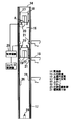
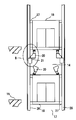
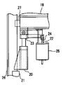
図1〜図7は、この発明の実施の形態の一例を示す図で、図1はエレベーター装置を概念的に示す立面図、図2は図1のA部拡大図、図3は図2の衝突受け体を拡大して示す側面図、図4は図3の平面図、図5は図1のエレベーター装置において下かごに上かごが異常接近した状態を示す図であり図1の要部拡大図に相当する図、図6は図5のB部拡大図、図7は図1のエレベーター装置の制御系の動作を説明するフローチャートである。
【0010】
図において、14は昇降路、15は昇降路14の昇降行程の中間に設けられた共用乗場、16は昇降路14を上下方向に分けて共用乗場15を含めて昇降路14の上方に形成された上運行区間、17は昇降路14を上下方向に分けて共用乗場15を含めて昇降路14の下方に形成された下運行区間、18は共用乗場15から上運行区間16を昇降する上かごである。
【0011】
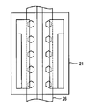
19は共用乗場15から下運行区間17を昇降する下かごである。なお、上かご18と下かご19はそれぞれに対応して設けられた駆動機(図示しない)によって、それぞれの運行区間を昇降運転される。20は上かご18の下降方向端部及び下かご19の上昇方向端部に設けられて作動方向が上下方向に配置された可変位緩衝器、21は昇降路に設けられて共用乗場15の上方隣接位置及び共用乗場15の下方隣接位置にそれぞれ配置されて可変位緩衝器20に対向して固定された衝突受け体である。
【0012】
22は電磁機構からなる移動機構で、L字状をなしL字の屈折部が上かご18又は下かご19に枢着され、L字の一端に可変位緩衝器20が装着された作動片23と、上かご18又は下かご19に取付けられて作動部24が作動片23のL字の他端に枢着された電磁アクチュエータ25とによって構成されている。そして、移動機構22の消勢時に可変位緩衝器20が衝突受け体21に対向する位置に保持され、また移動機構22の作動によって可変位緩衝器20が衝突受け体21に対して非対向位置に移動する。
【0013】
26は昇降路14に立設されて上かご18及び下かご19の両側に配置された案内レール、27は上かご18及び下かご19のそれぞれに設けられて案内レール26に移動可能に係合した案内具、28は昇降路14の底面に立設されて下かご19に対向して配置された昇降路用緩衝器、29は上かご18及び下かご19の移動機構20に接続された制御装置、30は制御装置29に接続されたエレベーター制御盤である。
【0014】
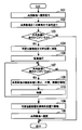
上記のように構成されたエレベーター装置において、上かご18及び下かご19の両者は可変位緩衝器20が衝突受け体21に対して非対向位置に保持された状態で、それぞれの上運行区間16又は下運行区間17を昇降運転される。そして、上記両者の一方が共用乗場15へ着床する場合の制御装置29、エレベーター制御盤30による制御を図7に示すフローチャートによって説明する。
【0015】
すなわち、ステップ101において上記両者の一方に共用乗場15への着床指令が発せられると、ステップ102へ進んで上記両者の一方が共用乗場15近くの乗場まで通常進行する。次いで、ステップ103に進んで周知のかご在否検出手段(図示しない)の出力の有無により共用乗場15に上記両者の他方がいればステップ104へ進み、上記両者の他方がいなければステップ105へ進む。
【0016】
そして、ステップ104において移動機構20の動作によって可変位緩衝器20が衝突受け体21に対して対向位置に移動する。次いで、ステップ106へ進み上記両者の一方は共用乗場15に向かって低速で進行する。そして、ステップ107へ進んで周知のかご在否検出手段(図示しない)の出力の有無により共用乗場15に上記両者の他方がいればステップ108へ進み、上記両者の他方がいなければステップ109へ進む。
【0017】
そして、ステップ108において上記両者の一方は共用乗場15の隣接乗場に停止して、戸開すると共にかご内の乗客に待機する旨を視覚的表示手段、聴覚的表示手段によって報知する。次いで、ステップ110へ進んで上記両者の一方は共用乗場15の隣接乗場において待機する。そして、制御ステップはステップ107へ戻り共用乗場15に上記両者の他方がいればステップ108、ステップ110へ戻り、また上記両者の他方がいなければステップ109へ進む。
【0018】
そして、ステップ109において移動機構20の動作によって可変位緩衝器20が衝突受け体21に対して非対向位置に移動してステップ105へ進む。そして、ステップ105において共用乗場15に上記両者の一方が着床する。
以上説明したように制御装置29等の制御による上記両者の昇降運転において、上記両者の一方が共用乗場15に着床する場合に上記両者の他方が共用乗場15にいるときに、上記両者の一方は共用乗場15の隣接乗場に待機する。
【0019】
しかし、エレベーター制御盤30等の制御系の故障によって上記両者の一方が共用乗場15の隣接乗場に待機せず共用乗場15に進行する場合に、可変位緩衝器20が衝突受け体21に対して対向位置に配置されている。このため、上記両者の一方の共用乗場15への進行動作が可変位緩衝器20の機能によって緩衝されて上記両者の一方が停止する。
【0020】
これによって、共用乗場15に滞留している上記両者の他方と上記両者の一方との衝突を未然に防ぐことができる。したがって、制御系の故障による二次的事故の発生を防止することができる。また、制御系の故障によって共用乗場15に進行する上記両者の一方が、可変位緩衝器20の緩衝機能によって減速停止するので、上記両者の一方が急停止してかご内の乗客に与える不快感を少なくすることができる。
【0021】
また、互いに並列に配置された複数の昇降路を設ける必要がなく、建物の水平投影面における所要スペースが減少して建設費を節減することができる。また、建物の上層階と下層階の間、すなわち上運行区間16と下運行区間17の間を乗客が移動する場合に、共用乗場15から同じ昇降路14のかごに乗り継ぐことができる。
【0022】
なお、昇降路14を複数の運行区間、例えば四運行区間に分けてそれぞれにかごを配置し、上下に隣接した運行区間の端部に共用乗場を設けたエレベーター装置において、共用乗場15に対して上方を上運行区間16とし、また共用乗場15に対して下方を下運行区間17としてエレベーター装置を構成する。このように構成されたエレベーター装置においても、図1〜図7の実施の形態における作用を得ることができる。
【0023】
【発明の効果】
この発明は以上説明したように、一つの昇降路を上下方向に分けて形成された上運行区間及び下運行区間と、昇降路に設けられて上運行区間の最下乗場であり、かつ下運行区間の最上乗場である共用乗場と、この共用乗場から上運行区間を昇降する上かご及び共用乗場から下運行区間を昇降する下かごと、上かごの下降方向端部及び下かごの上昇方向端部に設けられて作動方向が上下方向に配置された可変位緩衝器と、昇降路に設けられて共用乗場の上方隣接位置及び共用乗場の下方隣接位置にそれぞれ配置されて、可変位緩衝器に対向する位置に固定された衝突受け体と、可変位緩衝器に係合されて可変位緩衝器を移動し衝突受け体に対する対向位置及び非対向位置のいずれかに配置する移動機構と、この移動機構を介して常時は可変位緩衝器を衝突受け体に対して非対向位置に配置し、上かご及び下かごの両者の一方が共用乗場に滞留している場合に、上記両者の他方が所定位置を超えて共用乗場に接近するときに、上記両者の他方の可変位緩衝器を衝突受け体に対して対向位置に変位させる指令を移動機構に発する制御装置とを設けたものである。
【0024】
これによって、上記両者の昇降運転時に上記両者の一方が共用乗場に着床する場合に上記両者の他方が共用乗場にいるときに、上記両者の一方は共用乗場の隣接乗場に待機する。しかし、この状態においてエレベーター制御盤等の制御系の故障によって、上記両者の一方が共用乗場の隣接乗場に待機せず共用乗場に進行したときに、可変位緩衝器が衝突受け体に対する対向位置に配置されている。このため、上記両者の一方の共用乗場への進行動作が、可変位緩衝器の機能によって緩衝されて上記両者の一方が停止する。これにより、共用乗場に滞留している上記両者の他方と上記両者の一方との衝突を未然に防ぐことができる。したがって、制御系の故障による二次的事故の発生を防止する効果がある。また、制御系の故障によって共用乗場に進行する上記両者の一方が、可変位緩衝器の緩衝機能によって減速停止するので、上記両者の一方が急停止することによってかご内の乗客に与える不快感を減少する効果がある。
【図面の簡単な説明】
【図1】この発明の実施の形態1を示す図で、エレベーター装置を概念的に示す立面図。
【図2】図1のA部拡大図。
【図3】図2の衝突受け体を拡大して示す側面図。
【図4】図3の平面図。
【図5】図1のエレベーター装置において下かごに上かごが異常接近した状態を示す図であり、図1の要部拡大図に相当する図。
【図6】図5のB部拡大図。
【図7】図1のエレベーター装置の制御系の動作を説明するフローチャート。
【図8】従来のエレベーター装置を概念的に示す立面図。
【図9】他の従来のエレベーター装置を概念的に示す立面図。
【符号の説明】
14 昇降路、15 共用乗場、16 上運行区間、17 下運行区間、18上かご、19 下かご、20 可変位緩衝器、21 衝突受け体、22 移動機構、29 制御装置。[0001]
TECHNICAL FIELD OF THE INVENTION
The present invention relates to an elevator apparatus in which a car is arranged in each of a plurality of operation sections formed by dividing one hoistway in a vertical direction, and each of the plurality of cars is operated.
[0002]
[Prior art]
FIG. 8 is an elevational view conceptually showing a conventional elevator apparatus. In the figure, 1 to 3 are hoistways arranged in parallel with each other, 1 is a first hoistway, 2 is a second hoistway, and 3 is a third hoistway. 4 is a connecting floor provided in the middle of the first hoistway 1, the second hoistway 2, and the third hoistway 3 in the vertical direction, and 5 is above the connecting floor 4 of the first hoistway 1, that is, the upper floor of the building. The first car 6 is operated below the connecting floor 4 of the second hoistway 2, that is, the second car operated on the lower floor of the building, and the 7 is operated between the upper end and the lower end of the third hoistway 3. Is the third basket to be played.
[0003]
The conventional elevator apparatus is configured as described above, is provided with a first hoistway 1, a second hoistway 2, and a third hoistway 3, and the first car 5 is operated downward from the connecting floor 4 to the second hoistway. The car 6 is operated downward from the connecting floor 4, and the third car 3 is operated on the entire section of the hoistway. As a result, the three cars of the first car 5, the second car 6, and the third car 7 improve the transportation efficiency.
[0004]
FIG. 9 is an elevational view conceptually showing another conventional elevator apparatus. In the figure, 8 to 10 are hoistways, 8 is a first hoistway, 9 is a second hoistway arranged in series above the first hoistway 8, 10 is a third hoistway, It is arranged in parallel with the hoistway 8 and the second hoistway 9 and is provided between the top floor of the first hoistway 8 and the lowest floor of the second hoistway 9. 11 is a first car operated on the first hoistway 8, 12 is a second car operated on the second hoistway 9, and 13 is a third car operated on the third hoistway 10.
[0005]
Another conventional elevator apparatus is configured as described above, and is provided with a first hoistway 8, a second hoistway 9, and a third hoistway 10, and a lower car of a building (not shown) is provided with a first car 11. The upper floor is operated by the second car 12 and the third car 13 is operated between the upper end of the lower floor and the lower end of the upper floor. With such a configuration, the transportation efficiency of the first car 11, the second car 12, and the third car 13 is improved.
[0006]
[Problems to be solved by the invention]
In the conventional elevator apparatus shown in FIG. 8 or FIG. 9 described above, since a plurality of hoistways are arranged in parallel with each other, there is a problem that the required space on the horizontal projection plane of the building increases and the construction cost increases. Was. In addition, when a passenger moves between the upper floor and the lower floor of the building, the passenger is transferred to another elevator car arranged in parallel at the connecting floor.
[0007]
The present invention has been made in order to solve such a problem, and has a structure in which a car for the upper floor and a car for the lower floor are arranged in one hoistway, and is shared between the upper floor and the lower floor. It is an object of the present invention to provide an elevator apparatus that does not cause an obstacle due to poor control when a car arrives at a landing.
[0008]
[Means for Solving the Problems]
In the elevator device according to the present invention, the upper operating section and the lower operating section formed by vertically dividing one hoistway, and the lowest landing of the upper operating section provided in the hoistway, and the lower operating section The common landing that is the highest landing of the section, the upper car that moves up and down the upper operating section from this common landing, the lower car that moves up and down the lower operating section from the common landing, the lower end of the upper car, and the upper end of the lower car And a variable-position shock absorber provided in the section and having an operating direction arranged in the up-down direction, and a variable-position shock absorber provided in the hoistway and disposed at an upper adjacent position of the shared hall and a lower adjacent position of the shared hall, respectively, facing the variable shock absorber. A collision receiver fixed at a position to be moved, a moving mechanism engaged with the variable displacement shock absorber to move the variable displacement shock absorber and arrange it at one of a facing position and a non-facing position with respect to the collision receiving body, and the moving mechanism Always through When the variable shock absorber is disposed at a position not facing the collision receiver and one of the upper car and the lower car stays in the common hall, the other of the two cars exceeds a predetermined position and the common hall exceeds the predetermined position. And a control device for issuing to the moving mechanism a command to displace the other one of the two variable displacement buffers to a position facing the collision receiver when approaching the collision receiver.
[0009]
BEST MODE FOR CARRYING OUT THE INVENTION
Embodiment 1 FIG.
1 to 7 are views showing an example of an embodiment of the present invention. FIG. 1 is an elevation view conceptually showing an elevator apparatus, FIG. 2 is an enlarged view of a portion A in FIG. 1, and FIG. FIG. 4 is a plan view of FIG. 3, and FIG. 5 is a view showing a state in which the upper car abnormally approaches the lower car in the elevator apparatus of FIG. 1; FIG. FIG. 6 is an enlarged view corresponding to the enlarged view, FIG. 6 is an enlarged view of a portion B in FIG. 5, and FIG. 7 is a flowchart for explaining the operation of the control system of the elevator apparatus in FIG.
[0010]
In the figure, 14 is a hoistway, 15 is a common hall provided in the middle of the hoisting path of the hoistway 14, and 16 is formed above the hoistway 14 including the common hall 15 by dividing the hoistway 14 in the vertical direction. The upper operating section, 17 is a lower operating section formed below the hoistway 14 including the common hall 15 by dividing the hoistway 14 in the vertical direction, and 18 is an upper car that moves up and down the upper operating section 16 from the common hall 15. It is.
[0011]
Reference numeral 19 denotes a lower car that moves up and down the lower service section 17 from the common landing 15. The upper car 18 and the lower car 19 are driven up and down in their respective operation sections by driving devices (not shown) provided corresponding to the respective cars. Reference numeral 20 denotes a variable shock absorber which is provided at the lower end of the upper car 18 and the upper end of the lower car 19 and whose operating direction is vertically arranged, and 21 is provided on the hoistway and above the common landing 15. The collision receiver is disposed at an adjacent position and an adjacent position below the common landing 15 and fixed to face the variable displacement shock absorber 20.
[0012]
Reference numeral 22 denotes a moving mechanism composed of an electromagnetic mechanism. An operating piece 23 having an L-shape, an L-shaped bending portion pivotally attached to the upper car 18 or the lower car 19, and a variable displacement buffer 20 attached to one end of the L-shape. And an electromagnetic actuator 25 attached to the upper car 18 or the lower car 19 and having an operating portion 24 pivotally attached to the other end of the L-shaped operating piece 23. When the moving mechanism 22 is deenergized, the variable displacement shock absorber 20 is held at a position facing the collision receiver 21, and the operation of the moving mechanism 22 causes the variable displacement shock absorber 20 to move to a non-opposed position with respect to the collision receiver 21. Go to
[0013]
26 is a guide rail standing on the hoistway 14 and arranged on both sides of the upper car 18 and the lower car 19, and 27 is provided on each of the upper car 18 and the lower car 19 and movably engages with the guide rail 26. A guide device 28 is provided on a bottom surface of the hoistway 14, and is a buffer for the hoistway which is disposed to face the lower car 19. A control device 29 is connected to the moving mechanism 20 of the upper car 18 and the lower car 19. The device 30 is an elevator control panel connected to the control device 29.
[0014]
In the elevator apparatus configured as described above, both the upper car 18 and the lower car 19 have their respective upper running sections 16 in the state where the variable shock absorber 20 is held at the non-opposing position with respect to the collision receiver 21. Alternatively, the vehicle is driven up and down the lower operation section 17. The control by the control device 29 and the elevator control panel 30 in the case where one of the above two landings on the shared hall 15 will be described with reference to the flowchart shown in FIG.
[0015]
That is, when a landing command to the common hall 15 is issued to one of the two in step 101, the process proceeds to step 102, and one of the two normally proceeds to a hall near the common hall 15. Next, the routine proceeds to step 103, and if there is the other of the two in the shared hall 15 based on the presence or absence of the output of the well-known car presence / absence detecting means (not shown), the routine proceeds to step 104, and if not, to step 105. .
[0016]
Then, in step 104, the variable displacement shock absorber 20 moves to a position facing the collision receiver 21 by the operation of the moving mechanism 20. Next, the routine proceeds to step 106, where one of the two members travels at a low speed toward the common hall 15. Then, the process proceeds to step 107, and if there is the other of the two in the shared hall 15 according to the presence or absence of the output of the well-known car presence / absence detecting means (not shown), the process proceeds to step 108, and if not, the process proceeds to step 109. .
[0017]
Then, in step 108, one of the two stops at the landing adjacent to the common landing 15, opens the door, and informs the passengers in the car of the waiting by the visual display means and the auditory display means. Next, proceeding to step 110, one of the two stands by at a landing adjacent to the common landing 15. Then, the control step returns to step 107, and returns to step 108 and step 110 if the other is present in the common hall 15, and proceeds to step 109 if the other is not present.
[0018]
Then, in step 109, the variable displacement shock absorber 20 is moved to a position not facing the collision receiver 21 by the operation of the moving mechanism 20, and the process proceeds to step 105. Then, in step 105, one of the two landings at the common hall 15.
As described above, in the up / down operation under the control of the control device 29 or the like, when one of the two is landing on the common hall 15 and the other is in the common hall 15, one of the two Waits at the landing adjacent to the common landing 15.
[0019]
However, when one of the above two vehicles does not wait at the hall adjacent to the common hall 15 and proceeds to the common hall 15 due to a failure of the control system such as the elevator control panel 30, the variable displacement shock absorber 20 moves with respect to the collision receiver 21. It is arranged at the opposing position. For this reason, the operation of traveling to one of the common landings 15 is buffered by the function of the variable displacement buffer 20, and one of the two stops.
[0020]
As a result, it is possible to prevent a collision between the other of the above-mentioned two staying in the common landing 15 and one of the above-mentioned both. Therefore, it is possible to prevent the occurrence of a secondary accident due to the failure of the control system. In addition, since one of the two traveling to the common landing 15 due to the failure of the control system is decelerated and stopped by the buffer function of the variable displacement shock absorber 20, one of the two suddenly stops and gives an uncomfortable feeling to the passengers in the car. Can be reduced.
[0021]
Further, there is no need to provide a plurality of hoistways arranged in parallel with each other, and the required space on the horizontal projection plane of the building is reduced, so that construction costs can be reduced. Further, when the passenger moves between the upper floor and the lower floor of the building, that is, between the upper operation section 16 and the lower operation section 17, it is possible to transfer from the common hall 15 to the same elevator car.
[0022]
In the elevator apparatus in which the hoistway 14 is divided into a plurality of service sections, for example, four service sections, and a car is arranged in each section, and a shared platform is provided at the end of the vertically adjacent service section, The elevator device is configured such that the upper part is an upper operating section 16 and the lower part of the common landing 15 is a lower operating section 17. The operation of the embodiment of FIGS. 1 to 7 can also be obtained in the elevator device configured as described above.
[0023]
【The invention's effect】
As described above, the present invention is an upper operating section and a lower operating section formed by dividing one hoistway in the vertical direction, and a lower landing of the upper operating section provided in the hoistway, and a lower operating section. The common landing that is the highest landing of the section, the upper car that moves up and down the upper operating section from this common landing, the lower car that moves up and down the lower operating section from the common landing, the lower end of the upper car, and the upper end of the lower car A variable displacement shock absorber provided in the section and the operation direction is arranged in the vertical direction, and a variable displacement shock absorber provided in the hoistway and arranged at an upper adjacent position of the shared hall and a lower adjacent position of the shared hall, respectively, A collision receiver fixed at an opposing position, a moving mechanism engaged with the variable-position shock absorber to move the variable-position shock absorber and arrange it at one of an opposing position and a non-opposing position with respect to the collision receiver; Variable position through the mechanism The container is placed at a position not facing the collision receiver, and when one of the upper car and the lower car stays in the common hall, the other of the two cars approaches the common hall beyond a predetermined position. Sometimes, a control device is provided for issuing to the moving mechanism a command to displace the other of the two variable displacement buffers to a position facing the collision receiver.
[0024]
Thereby, when one of the two is landing on the common hall during the ascent / descent operation of the two and one of the two is on the common hall, one of the two stands by at the hall adjacent to the common hall. However, in this state, due to the failure of the control system such as the elevator control panel, when one of the above-mentioned two vehicles proceeds to the common hall without waiting at the adjacent hall of the common hall, the variable displacement shock absorber moves to the position facing the collision receiver. Are located. For this reason, the traveling operation to one of the two common landings is buffered by the function of the variable displacement buffer, and one of the two stops. As a result, it is possible to prevent a collision between the other of the above-mentioned two staying at the common landing and one of the above-mentioned both. Therefore, there is an effect of preventing occurrence of a secondary accident due to a failure of the control system. In addition, since one of the above-mentioned two which progresses to the common hall due to the failure of the control system is decelerated and stopped by the buffer function of the variable displacement shock absorber, the discomfort given to the passengers in the car by one of the above two suddenly stopping. Has the effect of reducing.
[Brief description of the drawings]
FIG. 1 is a view showing a first embodiment of the present invention, and is an elevation view conceptually showing an elevator apparatus.
FIG. 2 is an enlarged view of a portion A in FIG.
FIG. 3 is an enlarged side view showing the collision receiver of FIG. 2;
FIG. 4 is a plan view of FIG. 3;
5 is a diagram showing a state in which the upper car abnormally approaches the lower car in the elevator device of FIG. 1, and is a diagram corresponding to an enlarged view of a main part of FIG. 1;
FIG. 6 is an enlarged view of a portion B in FIG. 5;
FIG. 7 is a flowchart illustrating an operation of a control system of the elevator apparatus of FIG. 1;
FIG. 8 is an elevation view conceptually showing a conventional elevator apparatus.
FIG. 9 is an elevation view conceptually showing another conventional elevator apparatus.
[Explanation of symbols]
14 hoistway, 15 common landing, 16 upper operating section, 17 lower operating section, 18 upper car, 19 lower car, 20 variable shock absorber, 21 collision receiver, 22 moving mechanism, 29 control device.