JP2004018357A - Reforming reactor system - Google Patents
Reforming reactor system Download PDFInfo
- Publication number
- JP2004018357A JP2004018357A JP2002179654A JP2002179654A JP2004018357A JP 2004018357 A JP2004018357 A JP 2004018357A JP 2002179654 A JP2002179654 A JP 2002179654A JP 2002179654 A JP2002179654 A JP 2002179654A JP 2004018357 A JP2004018357 A JP 2004018357A
- Authority
- JP
- Japan
- Prior art keywords
- reforming
- gas
- reforming reactor
- heating chamber
- combustion
- Prior art date
- Legal status (The legal status is an assumption and is not a legal conclusion. Google has not performed a legal analysis and makes no representation as to the accuracy of the status listed.)
- Pending
Links
Images

Classifications
-
- Y—GENERAL TAGGING OF NEW TECHNOLOGICAL DEVELOPMENTS; GENERAL TAGGING OF CROSS-SECTIONAL TECHNOLOGIES SPANNING OVER SEVERAL SECTIONS OF THE IPC; TECHNICAL SUBJECTS COVERED BY FORMER USPC CROSS-REFERENCE ART COLLECTIONS [XRACs] AND DIGESTS
- Y02—TECHNOLOGIES OR APPLICATIONS FOR MITIGATION OR ADAPTATION AGAINST CLIMATE CHANGE
- Y02E—REDUCTION OF GREENHOUSE GAS [GHG] EMISSIONS, RELATED TO ENERGY GENERATION, TRANSMISSION OR DISTRIBUTION
- Y02E60/00—Enabling technologies; Technologies with a potential or indirect contribution to GHG emissions mitigation
- Y02E60/30—Hydrogen technology
- Y02E60/50—Fuel cells
Landscapes
- Hydrogen, Water And Hydrids (AREA)
- Fuel Cell (AREA)
Abstract
【課題】改質反応器における改質効率を向上させる。
【解決手段】改質反応器1の加熱室11の下流に燃焼触媒13を担持させ、燃料電池スタック4のアノードオフガスの一部を、燃焼器6をバイパスするバイパス通路16を介して改質反応器1の加熱室11に供給するようにした。
【選択図】 図1An object of the present invention is to improve reforming efficiency in a reforming reactor.
A combustion catalyst is carried downstream of a heating chamber of a reforming reactor, and a part of anode off-gas of a fuel cell stack is reformed through a bypass passage bypassing a combustor. The heating chamber 11 of the vessel 1 was supplied.
[Selection diagram] Fig. 1
Description
【0001】
【発明の属する技術分野】
本発明は、炭化水素化合物を水素リッチな燃料ガスに改質する改質反応器システムに関し、特に、改質反応器の改質触媒層の加熱に好適な改質反応器システムに関するものである。
【0002】
【従来の技術】
従来から改質反応器の改質触媒層を加熱するため、燃焼器を作動させる方法が提案されており、例えば、特開2001−223016号公報に記載されたものがある。
【0003】
これは、改質反応器により水素の豊富な燃料ガスを生成し、燃料ガスの一部は燃料電池スタックで消費され、スタックから排出されて燃焼器に供給される。燃焼器には、さらに、炭化水素の燃料と、燃料電池スタックへ供給される水素の豊富な燃料ガスとが供給される。燃焼器への水素の豊富な燃料ガスの量は、改質反応器の温度に従って調整するようにしている。
【0004】
【発明が解決しようとする課題】
しかしながら、上記従来例では、改質反応器、シフト反応器および酸化反応器等の反応チャンバ内における層状通路に燃焼器からの燃焼ガスを供給するものであるため、燃焼ガスは反応チャンバ内の層状通路を進むに連れて顕熱が消費されて温度低下するものであった。このため、例えば、改質反応器に改質反応のための熱を均等に供給できず、改質反応器内の温度分布が大きくなり、十分に燃料転化率を上昇させることが難しいものであった。
【0005】
そこで本発明は、上記問題点に鑑みてなされたもので、改質反応器における改質効率向上に好適な改質反応器システムを提供することを目的とする。
【0006】
【課題を解決するための手段】
本発明は、原燃料を改質触媒内に通過させて水蒸気改質反応により水素リッチな燃料ガスに改質する改質触媒層と、燃料電池スタックの排ガスを燃焼させる燃焼器の燃焼ガスを通過させて改質触媒層を加熱する加熱室とからなる改質反応器の加熱室の下流に燃焼触媒を担持させ、燃料電池スタックのアノードオフガスの一部を、燃焼器をバイパスするバイパス通路を介して改質反応器の加熱室に供給するようにした。
【0007】
【発明の効果】
したがって、本発明では、改質反応器の加熱室の下流に燃焼触媒を担持させ、燃料電池スタックのアノードオフガスの一部を、燃焼器をバイパスするバイパス通路を介して改質反応器の加熱室に供給するようにした。このため、改質反応器の改質触媒層の上流では、加熱室上流に流れ込む高温の燃焼ガスにより水蒸気改質が進み、水蒸気改質が進むと吸熱も進むため改質触媒内の温度も下流に行くに連れて下がり改質が進み難くなる。しかしながら、加熱室下流に担持した燃焼触媒が燃焼ガスと共に供給されたアノードオフガスを燃焼させ、改質触媒の下流において再度温度が上昇して改質が継続される。このため、改質原料の未反応分が発生せず、改質効率が向上する。
【0008】
【発明の実施の形態】
以下、本発明の改質反応器システムを各実施形態に基づいて説明する。
【0009】
(第1実施形態)
図1〜3は、本発明を適用した第1の実施形態の改質反応器システムを示し、図1は改質反応器システムのシステム構成図、図2は改質反応器の改質触媒層内の温度分布を示すグラフ、図3は改質反応器システムの変形例を示すシステム構成図である。
【0010】
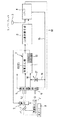
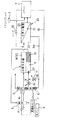
図1において、本実施形態の改質反応器システムは、プレートフインタイプの熱交換型反応器からなる改質反応器1と、改質反応器1よりの改質ガスのCO濃度を低下させるCO選択酸化器2と、CO選択酸化器2よりの改質ガス中の水素とエアコンプレッサ3よりの空気中の酸素との電気化学的反応により電力を取出す燃料電池スタック4とを備える。また、前記改質反応器1の改質触媒層10に気化された原燃料と水と供給する蒸発器5と、蒸発器5を加熱すると共に燃焼ガスを改質反応器1の加熱室11に供給する燃焼器6と、原燃料タンク7および水タンク8から夫々原燃料および水をプリヒートして気化された原燃料と水を発生させ蒸発器5に供給する熱交換器9とを備える。
【0011】
前記改質反応器1は、蒸発器5より供給された気化された原燃料および水を、内蔵する改質触媒12による水蒸気改質反応により水素リッチな燃料ガスに改質する改質触媒層10と、改質触媒層10の水蒸気改質反応に必要な熱を供給する加熱室11とを交互に複数組積層して備える。加熱室11はガス流れ方向中間部より下流側位置にのみに燃焼触媒13を担持して備える。加熱室11は燃焼器6より燃焼ガス通路14を経由して供給される燃焼ガスの熱により改質触媒層10を加熱する一方、下流側位置に担持した燃焼触媒13により燃焼ガス等の未燃焼成分を燃焼させて改質触媒層10の下流側を引続き加熱するようにしている。加熱室11を通過した燃焼ガスは前記熱交換器9を残余の熱で加熱する。加熱室11には、燃料電池スタック4の排ガスを燃焼器6に供給するアノードオフライン15を分岐して燃焼器6をバイパスするバイパス通路16を経由してアノードオフガスを導入可能としている。導入したアノードオフガスは前記燃焼触媒13により燃焼させる。アノードオフガスの導入量はバイパス通路16に挿入された流量制御バルブ17により制御する。
【0012】
前記CO選択酸化器2は、図示しないシフト反応器とPrOx反応器とを備え、改質ガスのCO濃度を低下させる。即ち、シフト反応器において一酸化炭素と水を反応させて、二酸化炭素と水素に生成し、引続き、PrOx反応器において改質ガス中に含まれる一酸化炭素を選択的に酸化し、その濃度を低減させる。
【0013】
前記燃料電池スタック4は、CO選択酸化器2よりの改質ガス中の水素とエアコンプレッサ3よりの空気中の酸素との電気化学的反応から電力を取出し、図示しない自動車のモータ若しくはバッテリに供給する。燃料電池スタック4の排ガスは(アノードオフガスおよびカソードオフガス)夫々のオフライン15、18を経由して前記燃焼器6に供給して燃焼器6内で燃焼させる。アノードオフガスは、燃焼器6に供給する他、バイパス通路16および流量制御バルブ17を経由して改質反応器1の加熱室11にも供給し、加熱室11の燃焼触媒13によって燃焼させる。
【0014】
前記燃焼器6は、前記アノードオフガスおよびカソードオフガスの未燃焼ガスを燃焼させてその燃焼ガスを改質反応器1の加熱室11に供給する。燃焼器6は、また、蒸発器5を加熱して熱交換器9でプリヒートされた原燃料および水を蒸発器5で気化させて改質反応器1の改質触媒層10に供給させる。
【0015】
以上の構成になる改質反応器システムの作動について説明する。
【0016】
改質反応器1の改質触媒層10には、蒸発器5により気化された原燃料と水との混合物が投入される一方、改質反応器1の加熱室11には燃焼器6の燃焼ガスとバイパス通路16および流量制御バルブ17を経由したアノードオフガスとの混合ガスが供給される。
【0017】
改質触媒層10では、原燃料が先ず最上流部分から水蒸気改質され始め、順次改質されながら下流に向かって流れる。加熱室11では、混合ガスがその顕熱を改質触媒層10に供給しつつ下流に流れ、担持した燃焼触媒13を通過する際には混合ガス中の未燃焼成分を含むアノードオフガスが燃焼される。
【0018】
加熱室11の混合ガスの温度は、図2に示すように、最上流で高く、下流に移るに連れて改質触媒層10での改質反応のために消費されて温度が低下してゆく。そして、混合ガスが加熱室11の後半部分に担持した燃焼触媒13に達すると、未燃焼成分を含むアノードオフガスが燃焼されて混合ガスの温度は再び上昇され、以後、下流に移るに連れて改質触媒層10での改質反応のために消費されて温度が低下してゆく。このため、加熱室11の温度が低下してしまい、改質触媒層10へ顕熱を供給できない事態が避けられ、改質触媒層10での原燃料の水蒸気改質は、改質触媒層10の最上流から最下流まで万遍なく継続される。従って、従来のように、改質されずに未反応状態で排出されてしまう原料がなくなり、改質の効率が上昇して、自動車システムとしては、燃費の向上や改質器システム自体の小型化ができるという特徴を発揮する。
【0019】
図3は本実施形態の改質反応器システムの変形例を示すものであり、燃焼器6の燃焼ガスを改質反応器1の加熱室11に供給する燃焼ガス通路14に燃焼ガスの流量を調整可能な流量制御バルブ19を追加したものである。
【0020】
この変形例によれば、改質反応器1の加熱室11に供給する混合ガスは、燃焼器6の燃焼ガスとアノードオフガスとの混合割合を調節することで、最上流温度および中流温度を任意に調節することができる。このため、改質反応の負荷に応じて加熱条件を調整することができる。
【0021】
本実施形態においては、下記に記載した効果を奏することができる。
【0022】
(ア)原燃料を内蔵した改質触媒12内を通過させて水蒸気改質反応により水素リッチな燃料ガスに改質する改質触媒層10と、燃料電池スタック4の排ガスを燃焼させる燃焼器6の燃焼ガスを通過させて改質触媒層10を加熱する加熱室11とからなる改質反応器1において、改質反応器1の加熱室11の下流に燃焼触媒13を担持させ、燃料電池スタック4のアノードオフガスの一部を、燃焼器6をバイパスするバイパス通路16を介して改質反応器1の加熱室11に供給するようにしている。このため、改質反応器1の改質触媒層10の上流では、加熱室11上流に流れ込む高温の燃焼ガスにより水蒸気改質が進み、水蒸気改質が進むと吸熱も進むため改質触媒内の温度も下流に行くに連れて下がり改質が進み難くなる。しかしながら、加熱室11下流に担持した燃焼触媒13が燃焼ガスと共に供給されたアノードオフガスを燃焼させ、改質触媒12の下流において再度温度が上昇して改質が継続される。従って、改質原料の未反応分が発生せず、改質効率が向上する。
【0023】
(イ)図3に示す改質反応器システムでは、燃焼器6から改質反応器1に燃焼ガスを供給する燃焼ガス通路14とバイパス通路16とに、夫々の流量を調整する流量制御バルブ17、19を設けているので、加熱室11に投入する燃焼器6の燃焼ガスと燃料電池4のアノードオフガスとの比を自由に変更させることができ、加熱室11上流と加熱室11下流との温度分布を調整することができ、運転負荷に応じて常に最適な温度分布を実現することができる。
【0024】
(第2実施形態)
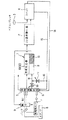
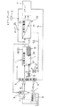
図4〜6は、本発明を適用した第2の実施形態の改質反応器システムを示し、改質反応器1の改質ガスを燃料電池スタック4に供給する経路に、CO選択酸化器を経由させることに代えて水素分離器20を経由させるようにしたものである。図4は改質反応器システムのシステム構成図、図5は第2実施形態の改質反応器システムの第1の変形例のシステム構成図、図6は第2、3の変形例を示すシステム構成図である。なお、第1の実施形態と同一部品には同一符号を付して説明を簡略化し、新規な部分について詳細に説明する。
【0025】
図4において、本実施形態の改質反応器システムは、水素分離器20を経由して改質反応器1の改質ガスを燃料電池スタック4に供給するようにしている。前記水素分離器20は、水素分離膜21により区画して一次側22と二次側23との室を備え、いずれか一方の水素分圧が他方の水素分圧より高い場合に、水素分圧の低い側へ水素を選択的に透過させて水素分圧をバランスさせるよう機能する。この実施形態の水素分離器20は、一次側22に改質反応器1の改質ガスを供給し、二次側23の水素分圧に対して一次側22の水素分圧が上昇するとき水素分離膜21を透過させて一次側22の水素を二次側23へ移動させるよう作動する。
【0026】
また、燃料電池スタック4のアノードオフガスは、循環ポンプ25を経由して水素分離器20の一次側22に戻され、循環ポンプ25により水素分離器20の一次側22は高圧となる。さらに、水素分離器20の一次側22はガス流路15Aを介して燃焼器6およびバイパス通路16を介して改質反応器1の加熱室11に供給される。
【0027】
以上の構成においては、改質反応器1により改質された改質ガスは水素分離器20の一次側22に送られ、その改質ガス中の水素は水素分離膜21を透過して二次側23に移動し、アノードガスとして燃料電池スタック4に供給される。燃料電池スタック4のアノードオフガスは循環ポンプ25で水素分離器20の一次側22に戻される。循環ポンプ25で高圧となった一次側22のガスは、上記のように再度水素分離膜21により二次側23に水素を透過させる一方、ガス流路15Aを介して燃焼器6に供給され、燃焼ガス流路14、バイパス通路16および流量調整弁17、19を経由して改質反応器1の加熱室11に混合ガスとして供給される。
【0028】
燃焼器6及び改質反応器1の加熱室11に供給する水素分離器20の一次側22のガスは、循環ポンプ25により高圧となっており、過渡応答時には、瞬時に一次側22のガスおよび燃焼器6からの燃焼ガスを加熱室11に供給でき、改質触媒層10を瞬時に加熱することができ、改質反応器システムとして、応答性を向上できる。また、一次側22のガスは、燃料電池スタック4を経由しないで直接供給されるため、その分の経路が短く、応答性を向上できる。
【0029】
図5に示す第1の変形例は、図4の実施形態の改質反応器システムにおいて、改質反応器1の加熱室11の燃焼触媒13の最上流に温度センサ26を設け、燃焼触媒13が触媒活性化温度未満である場合には、燃焼ガス通路14の流量調整弁19は開弁したまま、バイパス通路16の流量調整弁17を閉弁させるようにしたものである。
【0030】
この第1の変形例では、起動時等において、温度センサ26による燃焼触媒13の温度が触媒活性化温度未満である場合には、バイパス通路16の流量調整弁17を閉弁させる一方、燃焼ガス通路14の流量調整弁19は開弁させ、温度センサ26による燃焼触媒13の温度が触媒活性化温度に達した場合には、バイパス通路16の流量調整弁17を設定した開度に開弁させる一方、燃焼ガス通路14の流量調整弁19は通常開度に開弁させる。このため、もし、燃焼触媒13が活性化温度に達しないうちに、水素分離膜21の一次側22のガスを改質反応器1の加熱室11に投入してしまうと、燃焼触媒13でのガス燃焼が発生せずに、排気されてしまうことを防止できる。
【0031】
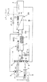
図6に示す第2の変形例は、図4の実施形態の改質反応器システムにおいて、改質反応器1の加熱室11の最上流に温度センサ27を設け、燃料電池4の定常低負荷運転時には、温度センサ27が所定の温度になるように、燃焼ガス通路14の流量調整弁19は開弁したまま、バイパス通路16の流量調整弁17を閉弁させるようにしたものである。
【0032】
この第2の変形例では、定常低負荷運転時において、温度センサ27による加熱室11の温度が改質触媒層10での改質が得られる温度未満である場合には、バイパス通路16の流量調整弁17を閉弁させる一方、燃焼ガス通路14の流量調整弁19は開弁させ、温度センサ27による温度が改質温度に達した場合には、バイパス通路16の流量調整弁17を設定した開度に開弁させる一方、燃焼ガス通路14の流量調整弁19を通常開度に開弁させる。水素分離器20の一次側22の排気ガスはすべて燃焼器6へ供給でき、燃焼ガスによって加熱室11の上流を加熱できる。このため、改質反応器1の加熱室11での加熱量に対する放熱の割合が大きく改質温度が確保しにくい定常低負荷運転においても、十分な改質性能を維持できる。
【0033】
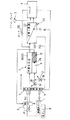
図7に示す第3の変形例は、図4の実施形態の改質反応器システムにおいて、改質反応器1の加熱室11と燃焼触媒13との両者の最上流に温度センサ26、27を設ける。そして、燃料電池4の高負荷運転時には、予め改質効率が最も良くなる温度条件を図示しないコントローラに記憶させ、温度センサ26、27の温度が記憶した温度条件と一致するよう燃焼ガス通路14とバイパス通路16とに配置した流量調整弁17、19の各開度を調整するようにしたものである。
【0034】
本来、高負荷運転時においては、改質反応器1の改質触媒層10の温度は入口部で高いが改質が進む下流において低下して改質が進まなくなり、原料が未反応の状態で多く排出される。
【0035】
しかしながら、この第3の変形例では、改質反応器1の加熱室11の下流に坦持させた燃焼触媒13により、燃焼ガスと同時に供給された水素分離器20の一次側22のガスを再度燃焼させて、改質触媒層10の下流での温度を再度上昇させて改質反応が継続される。そして、改質反応器1の改質触媒層10の温度分布が予め改質効率が最も良くなる温度条件となるよう各温度センサ26、27の計測温度に基づき燃焼ガス通路14とバイパス通路16との流量調整弁17、19の各開度を調整するため、改質原料の未反応分が発生せず、改質効率を向上できる。
【0036】
本実施形態においては、第1実施形態における効果(ア)、(イ)に加えて、下記に記載する効果を奏することができる。
【0037】
(ウ)改質反応器1の改質ガスは、二次側23が燃料電池スタック4のアノードに連通される水素分離膜21の一次側22に供給され、燃料電池スタック4のアノードオフガスを水素分離膜21の一次側22に循環させ、一次側22から燃焼器6およびバイパス通路16に供給するため、燃焼器6および加熱室11に高圧で水素分離膜21の一次側22の改質ガスを供給でき、過渡応答時に瞬時に一次側22の改質ガス(アノードオフガス)および燃焼器6の燃焼ガスを加熱室11に供給して改質触媒12を早急に加熱することができ、改質器システムとして、応答性が向上する。しかも、一次側22の改質ガス(アノードオフガス)は燃料電池スタック4を経由することなく供給できるため、経路が短く応答性を向上できる。
【0038】
(エ)図5に示す改質反応器システムにおいては、加熱室11の燃焼触媒13を担持している範囲で最も上流側に温度センサ26を設け、起動時には、温度センサ26からの温度が触媒活性化温度に上がるまで、バイパス通路16の流量制御バルブ17を閉とし、燃焼ガス通路14の流量制御バルブ19を開とするため、燃焼室11内の燃焼触媒13が活性化温度に達しないうちに水素分離膜21の一次側22の排ガスを燃焼室11に投入してしまうことに起因して、燃焼触媒13での排ガス燃焼が行われずに排気されてしまうことが防止できる効果を有する。
【0039】
(オ)図6に示す改質反応器システムにおいては、加熱室11の上流側の入口部分に温度センサ27を設け、定常低負荷時においては、温度センサ27が所定の温度になるように、バイパス通路16の流量制御バルブ17を閉じ、燃焼ガス通路14の流量制御バルブ19を開とする。このため、通常低負荷運転においては、改質反応器1の加熱室11での加熱量に対する放熱の割合が大きく、改質温度が確保しにくいが、温度センサ27により十分な改質温度が得られるように、水素分離膜21からの排気ガスはすべて燃焼器6へ供給して加熱室11上流を加熱して、低負荷時においても十分な改質性能を維持できる。
【0040】
(カ)図7に示す改質反応器システムにおいては、加熱室11の燃焼触媒13の上流端と加熱室11入口部分とに夫々温度センサ26、27を設け、高負荷運転時においては、夫々の温度センサ26、27による温度が、改質触媒12の耐熱上限温度に近くなるように、バイパス通路16と燃焼ガス通路14との流量制御バルブ17、19の開度を制御する。本来、高負荷運転時においては、改質触媒12の入口部は高いが改質が進むと下流においては温度が下がり、改質が進まなくなるため、原料が未反応の状態で多く排出される。しかし、本改質反応器システムでは、加熱室11の下流に燃焼触媒を13坦持し、燃焼ガスと同時に供給された水素分離膜21の一次側22の排ガスがそこで再度燃焼して改質触媒12の下流で再度温度を上昇させて改質が継続される。従って、改質原料の未反応分が発生せず、改質効率が向上する。
【図面の簡単な説明】
【図1】本発明の一実施形態を示す改質反応器システムの概略構成図。
【図2】同じく改質反応器の改質触媒層内の温度分布を示すグラフ。
【図3】第1実施形態の変形例を示す改質反応器システムの概略構成図。
【図4】本発明の第2実施形態の改質反応器システムの概略構成図。
【図5】第2実施形態の変形例を示す改質反応器システムの概略構成図。
【図6】第2実施形態の第2の変形例を示す改質反応器システムの概略構成図。
【図7】第2実施形態の第3の変形例を示す改質反応器システムの概略構成図。
【符号の説明】
1 改質反応器
2 CO選択酸化器
4 燃料電池スタック
5 蒸発器
6 燃焼器
10 改質触媒層
11 加熱室
13 燃焼触媒
14 燃焼ガス通路
15 アノードオフライン
15A ガス流路
16 バイパス通路
17、19 流量制御弁
20 水素分離器
21 水素分離膜
22 一次側
25 循環ポンプ
26、27 温度センサ[0001]
TECHNICAL FIELD OF THE INVENTION
The present invention relates to a reforming reactor system for reforming a hydrocarbon compound into a hydrogen-rich fuel gas, and more particularly to a reforming reactor system suitable for heating a reforming catalyst layer of a reforming reactor.
[0002]
[Prior art]
Conventionally, a method of operating a combustor to heat a reforming catalyst layer of a reforming reactor has been proposed, for example, a method described in JP-A-2001-22230.
[0003]
This produces a hydrogen-rich fuel gas by the reforming reactor, and a portion of the fuel gas is consumed by the fuel cell stack, exhausted from the stack and supplied to the combustor. The combustor is also supplied with hydrocarbon fuel and hydrogen-rich fuel gas supplied to the fuel cell stack. The amount of hydrogen-rich fuel gas to the combustor is adjusted according to the temperature of the reforming reactor.
[0004]
[Problems to be solved by the invention]
However, in the above-described conventional example, the combustion gas from the combustor is supplied to the laminar passage in the reaction chamber such as the reforming reactor, the shift reactor, and the oxidation reactor. The sensible heat was consumed and the temperature decreased as it proceeded along the passage. For this reason, for example, heat for the reforming reaction cannot be uniformly supplied to the reforming reactor, the temperature distribution in the reforming reactor increases, and it is difficult to sufficiently increase the fuel conversion rate. Was.
[0005]
Therefore, the present invention has been made in view of the above problems, and an object of the present invention is to provide a reforming reactor system suitable for improving reforming efficiency in a reforming reactor.
[0006]
[Means for Solving the Problems]
The present invention passes a reforming catalyst layer that feeds a raw fuel into a reforming catalyst and reforms it into a hydrogen-rich fuel gas by a steam reforming reaction, and a combustion gas from a combustor that burns exhaust gas of a fuel cell stack. A heating chamber that heats the reforming catalyst layer to carry a combustion catalyst downstream of the heating chamber of the reforming reactor, and a part of the anode offgas of the fuel cell stack is passed through a bypass passage that bypasses the combustor. To supply it to the heating chamber of the reforming reactor.
[0007]
【The invention's effect】
Therefore, in the present invention, the combustion catalyst is carried downstream of the heating chamber of the reforming reactor, and a part of the anode off-gas of the fuel cell stack is transferred to the heating chamber of the reforming reactor via the bypass passage that bypasses the combustor. To be supplied. Therefore, upstream of the reforming catalyst layer of the reforming reactor, steam reforming proceeds due to high-temperature combustion gas flowing upstream of the heating chamber. And the reforming becomes difficult to proceed. However, the combustion catalyst carried downstream of the heating chamber burns the anode off-gas supplied together with the combustion gas, and the temperature rises again downstream of the reforming catalyst to continue reforming. For this reason, unreacted components of the reforming raw material are not generated, and the reforming efficiency is improved.
[0008]
BEST MODE FOR CARRYING OUT THE INVENTION
Hereinafter, the reforming reactor system of the present invention will be described based on each embodiment.
[0009]
(1st Embodiment)
1 to 3 show a reforming reactor system according to a first embodiment to which the present invention is applied, FIG. 1 is a system configuration diagram of the reforming reactor system, and FIG. 2 is a reforming catalyst layer of the reforming reactor. FIG. 3 is a system configuration diagram showing a modification of the reforming reactor system.
[0010]
In FIG. 1, the reforming reactor system according to the present embodiment includes a reforming reactor 1 composed of a plate-fin type heat exchange reactor and a CO that reduces the CO concentration of the reformed gas from the reforming reactor 1. The fuel cell stack 4 includes a
[0011]
The reforming reactor 1 includes a reforming
[0012]
The CO
[0013]
The fuel cell stack 4 extracts electric power from an electrochemical reaction between hydrogen in the reformed gas from the CO
[0014]
The
[0015]
The operation of the reforming reactor system having the above configuration will be described.
[0016]
While the mixture of the raw fuel and water vaporized by the
[0017]
In the reforming
[0018]
As shown in FIG. 2, the temperature of the mixed gas in the
[0019]
FIG. 3 shows a modified example of the reforming reactor system of the present embodiment, in which the flow rate of the combustion gas is supplied to a
[0020]
According to this modification, the mixed gas supplied to the
[0021]
In the present embodiment, the following effects can be obtained.
[0022]
(A) A reforming
[0023]
(A) In the reforming reactor system shown in FIG. 3, a
[0024]
(2nd Embodiment)
4 to 6 show a reforming reactor system according to a second embodiment to which the present invention is applied. A CO selective oxidizer is provided in a path for supplying the reformed gas of the reforming reactor 1 to the fuel cell stack 4. Instead of passing through, the
[0025]
In FIG. 4, the reforming reactor system of the present embodiment is configured to supply the reformed gas of the reforming reactor 1 to the fuel cell stack 4 via the
[0026]
The anode off-gas of the fuel cell stack 4 is returned to the
[0027]
In the above configuration, the reformed gas reformed by the reforming reactor 1 is sent to the
[0028]
The gas on the
[0029]
A first modification shown in FIG. 5 is different from the reforming reactor system of the embodiment in FIG. 4 in that a
[0030]
In the first modified example, when the temperature of the
[0031]
The second modification shown in FIG. 6 is different from the reforming reactor system of the embodiment in FIG. 4 in that a
[0032]
In the second modified example, when the temperature of the
[0033]
In a third modification shown in FIG. 7, in the reforming reactor system of the embodiment of FIG. 4,
[0034]
Originally, at the time of high load operation, the temperature of the reforming
[0035]
However, in the third modification, the gas on the
[0036]
In the present embodiment, the following effects can be obtained in addition to the effects (A) and (A) of the first embodiment.
[0037]
(C) The reformed gas of the reforming reactor 1 is supplied to the
[0038]
(D) In the reforming reactor system shown in FIG. 5, a
[0039]
(E) In the reforming reactor system shown in FIG. 6, a
[0040]
(F) In the reforming reactor system shown in FIG. 7,
[Brief description of the drawings]
FIG. 1 is a schematic configuration diagram of a reforming reactor system showing one embodiment of the present invention.
FIG. 2 is a graph showing a temperature distribution in a reforming catalyst layer of the reforming reactor.
FIG. 3 is a schematic configuration diagram of a reforming reactor system showing a modification of the first embodiment.
FIG. 4 is a schematic configuration diagram of a reforming reactor system according to a second embodiment of the present invention.
FIG. 5 is a schematic configuration diagram of a reforming reactor system showing a modification of the second embodiment.
FIG. 6 is a schematic configuration diagram of a reforming reactor system showing a second modification of the second embodiment.
FIG. 7 is a schematic configuration diagram of a reforming reactor system showing a third modification of the second embodiment.
[Explanation of symbols]
DESCRIPTION OF SYMBOLS 1
Claims (6)
前記改質反応器の加熱室の下流に燃焼触媒を担持させ、
前記燃焼器に供給するアノードオフガスの一部を、燃焼器をバイパスするバイパス通路を介して改質反応器の加熱室に供給することを特徴とする改質反応器システム。A combustor for supplying a combustion gas obtained by burning the anode off gas and the cathode off gas of the fuel cell stack to the reforming reactor, and passing the supplied raw fuel through a reforming catalyst to obtain a hydrogen-rich gas by a steam reforming reaction. A reforming reactor system comprising a reforming catalyst layer for reforming to a fuel gas and a heating chamber for heating the reforming catalyst layer by passing the combustion gas therethrough,
A combustion catalyst is carried downstream of the heating chamber of the reforming reactor,
A reforming reactor system, wherein a part of the anode off-gas supplied to the combustor is supplied to a heating chamber of the reforming reactor via a bypass passage that bypasses the combustor.
起動時には、温度センサからの温度が触媒活性化温度に上がるまで、バイパス通路の流量制御バルブを閉とし、燃焼ガス通路の流量制御バルブを開とすることを特徴とする請求項3に記載の改質反応器システム。The heating chamber is provided with a temperature sensor on the most upstream side in a range where the combustion catalyst is supported,
4. The modification according to claim 3, wherein at startup, the flow control valve in the bypass passage is closed and the flow control valve in the combustion gas passage is opened until the temperature from the temperature sensor rises to the catalyst activation temperature. Quality reactor system.
定常低負荷時においては、温度センサが所定の温度になるように、バイパス通路の流量制御バルブを閉じ、燃焼ガス通路の流量制御バルブを開とすることを特徴とする請求項3に記載の改質反応器システム。The heating chamber is provided with a temperature sensor at an inlet portion on the upstream side,
4. The improvement according to claim 3, wherein the flow rate control valve in the bypass passage is closed and the flow rate control valve in the combustion gas passage is opened so that the temperature sensor reaches a predetermined temperature at a steady low load. Quality reactor system.
高負荷運転時においては、夫々の温度センサによる温度が、改質触媒の耐熱上限温度に近くなるように、バイパス通路と燃焼ガス通路との流量制御バルブの開度を制御することを特徴とする請求項3に記載の改質反応器システム。The heating chamber includes a temperature sensor at each of the upstream end of the combustion catalyst and the heating chamber inlet,
At the time of high load operation, the opening degree of the flow control valve between the bypass passage and the combustion gas passage is controlled so that the temperature detected by each temperature sensor is close to the upper limit temperature of the reforming catalyst. The reforming reactor system according to claim 3.
Priority Applications (1)
| Application Number | Priority Date | Filing Date | Title |
|---|---|---|---|
| JP2002179654A JP2004018357A (en) | 2002-06-20 | 2002-06-20 | Reforming reactor system |
Applications Claiming Priority (1)
| Application Number | Priority Date | Filing Date | Title |
|---|---|---|---|
| JP2002179654A JP2004018357A (en) | 2002-06-20 | 2002-06-20 | Reforming reactor system |
Publications (1)
| Publication Number | Publication Date |
|---|---|
| JP2004018357A true JP2004018357A (en) | 2004-01-22 |
Family
ID=31177005
Family Applications (1)
| Application Number | Title | Priority Date | Filing Date |
|---|---|---|---|
| JP2002179654A Pending JP2004018357A (en) | 2002-06-20 | 2002-06-20 | Reforming reactor system |
Country Status (1)
| Country | Link |
|---|---|
| JP (1) | JP2004018357A (en) |
Cited By (7)
| Publication number | Priority date | Publication date | Assignee | Title |
|---|---|---|---|---|
| JP2006272120A (en) * | 2005-03-29 | 2006-10-12 | Casio Comput Co Ltd | Vaporizer and vaporizing method |
| JP2008247738A (en) * | 2008-06-16 | 2008-10-16 | Casio Comput Co Ltd | Vaporizer and liquid absorption part |
| JP2009234909A (en) * | 2009-05-29 | 2009-10-15 | Casio Comput Co Ltd | Reactor |
| US7712729B2 (en) | 2005-03-29 | 2010-05-11 | Casio Computer Co., Ltd. | Vaporizing device and liquid absorbing member |
| JP2015011885A (en) * | 2013-06-28 | 2015-01-19 | 株式会社デンソー | Fuel cell system |
| JP2016184504A (en) * | 2015-03-26 | 2016-10-20 | 東京瓦斯株式会社 | Fuel cell system |
| JP2018098110A (en) * | 2016-12-16 | 2018-06-21 | 東京瓦斯株式会社 | Fuel cell system |
-
2002
- 2002-06-20 JP JP2002179654A patent/JP2004018357A/en active Pending
Cited By (7)
| Publication number | Priority date | Publication date | Assignee | Title |
|---|---|---|---|---|
| JP2006272120A (en) * | 2005-03-29 | 2006-10-12 | Casio Comput Co Ltd | Vaporizer and vaporizing method |
| US7712729B2 (en) | 2005-03-29 | 2010-05-11 | Casio Computer Co., Ltd. | Vaporizing device and liquid absorbing member |
| JP2008247738A (en) * | 2008-06-16 | 2008-10-16 | Casio Comput Co Ltd | Vaporizer and liquid absorption part |
| JP2009234909A (en) * | 2009-05-29 | 2009-10-15 | Casio Comput Co Ltd | Reactor |
| JP2015011885A (en) * | 2013-06-28 | 2015-01-19 | 株式会社デンソー | Fuel cell system |
| JP2016184504A (en) * | 2015-03-26 | 2016-10-20 | 東京瓦斯株式会社 | Fuel cell system |
| JP2018098110A (en) * | 2016-12-16 | 2018-06-21 | 東京瓦斯株式会社 | Fuel cell system |
Similar Documents
| Publication | Publication Date | Title |
|---|---|---|
| US6838062B2 (en) | Integrated fuel processor for rapid start and operational control | |
| US6926748B2 (en) | Staged lean combustion for rapid start of a fuel processor | |
| JP4515253B2 (en) | Fuel cell system | |
| US7838161B2 (en) | Reformer and fuel cell system using the same | |
| JP2003300704A (en) | Fuel reforming system and fuel cell system | |
| JP5763405B2 (en) | Fuel cell system | |
| JP2008529218A (en) | Fuel cell power plant | |
| JP4147659B2 (en) | Control device for reformer | |
| US7132002B2 (en) | Hydrogen generating device having hydrogen separator membrane and control method therefor | |
| KR20010075696A (en) | Apparatus for producing hydrogen gas and fuel cell system using the same | |
| JP2004018357A (en) | Reforming reactor system | |
| JP5324752B2 (en) | Hydrogen-containing gas generator | |
| JP2004196611A (en) | Fuel reformer and fuel cell system | |
| JP2000327303A (en) | Fuel reformer | |
| JP2001206701A (en) | Fuel reformer and start-up method thereof | |
| JP4599634B2 (en) | Fuel cell system | |
| JP5274003B2 (en) | Fuel cell system | |
| JP4867214B2 (en) | Fuel cell system | |
| JP2007165130A (en) | FUEL CELL SYSTEM AND CONTROL METHOD FOR FUEL CELL SYSTEM | |
| EP4546472A1 (en) | Thermal management of high-temperature electrochemical devices | |
| JPH04284365A (en) | Fuel cell power generating device | |
| JP2015140285A (en) | Method for operating hydrogen-containing gas generation apparatus, and hydrogen-containing gas generation apparatus | |
| JP7805275B2 (en) | Electrosynthesis System | |
| JP2010282909A (en) | Fuel cell system | |
| JP2007220424A (en) | Reformer and fuel cell system |