JP2004019461A - Control device for compressor motor - Google Patents
Control device for compressor motor Download PDFInfo
- Publication number
- JP2004019461A JP2004019461A JP2002171578A JP2002171578A JP2004019461A JP 2004019461 A JP2004019461 A JP 2004019461A JP 2002171578 A JP2002171578 A JP 2002171578A JP 2002171578 A JP2002171578 A JP 2002171578A JP 2004019461 A JP2004019461 A JP 2004019461A
- Authority
- JP
- Japan
- Prior art keywords
- start position
- compression start
- motor
- compressor
- detection unit
- Prior art date
- Legal status (The legal status is an assumption and is not a legal conclusion. Google has not performed a legal analysis and makes no representation as to the accuracy of the status listed.)
- Withdrawn
Links
- 230000006835 compression Effects 0.000 claims abstract description 92
- 238000007906 compression Methods 0.000 claims abstract description 92
- 238000001514 detection method Methods 0.000 claims abstract description 56
- 238000009434 installation Methods 0.000 description 8
- 238000010586 diagram Methods 0.000 description 5
- 238000004519 manufacturing process Methods 0.000 description 3
- 238000004364 calculation method Methods 0.000 description 2
- 238000000034 method Methods 0.000 description 2
- 238000004088 simulation Methods 0.000 description 2
- 238000012935 Averaging Methods 0.000 description 1
- 230000003213 activating effect Effects 0.000 description 1
- 238000006073 displacement reaction Methods 0.000 description 1
- 230000000694 effects Effects 0.000 description 1
- 230000007274 generation of a signal involved in cell-cell signaling Effects 0.000 description 1
- 230000010355 oscillation Effects 0.000 description 1
Images
Landscapes
- Control Of Positive-Displacement Pumps (AREA)
Abstract
Description
【0001】
【発明の属する技術分野】
本発明は、圧縮機用電動機の制御装置に関し、特に圧縮機を駆動する電動機の振動を低減する技術に関する。
【0002】
【従来の技術】
従来、圧縮機を駆動するための電動機を制御する制御装置が知られている。このような制御装置として、例えば特開2001−295769は、圧縮機の駆動トルクと負荷トルクの不平衡に起因して発生する回転振動を低減することができる「圧縮機用モータの制御装置」を開示している。
【0003】
この圧縮機用モータの制御装置は、圧縮機の1回転中の負荷トルクの変化パターンに対応したパターンで変化する係数を、トルク制御パターンとして予め記憶させた記憶手段を備えている。そして、モータの回転角度を検出し、この検出された回転角度に対応する係数を記憶手段から読み出し、この読み出した係数をモータの回転数偏差に対応する平均電圧指令に乗算して新たな電圧指令を生成し、この生成された新たな電圧指令に基づいてモータを駆動することにより、モータのトルクを1回転中における負荷トルクの変化に追従させている。
【0004】
【発明が解決しようとする課題】
ところで、上述した圧縮機用モータの制御装置は、圧縮機の圧縮開始位置を検出し、この検出された圧縮開始位置を基準にしてトルク制御パターンの読み出しを開始する。そして、このトルク制御パターンに基づいて新たな電圧指令を生成してモータを駆動する。
【0005】
しかしながら、圧縮開始位置は機械的に決定されるため、圧縮機製造時において、モータのステータを圧縮機に組み込む際に、組み込み角度にバラツキが生じて組み込み誤差が発生する。その結果、圧縮開始位置にズレが発生して回転振動の原因になっている。
【0006】
そこで、本発明の目的は、圧縮機の圧縮開始位置に誤差が生じても回転振動を抑えることができる圧縮機用電動機の制御装置を提供することにある。
【0007】
【課題を解決するための手段】
以下に、[発明の実施の形態]で使用する番号・符号を用いて、課題を解決するための手段を説明する。これらの番号・符号は、[特許請求の範囲]の記載と[発明の実施の形態]の記載との対応関係を明らかにするために付加されたものであるが、[特許請求の範囲]に記載されている発明の技術的範囲の解釈に用いてはならない。
【0008】
本発明に係る圧縮機用電動機の制御装置は、上記目的を達成するために、圧縮機を駆動する電動機(3)の回転数偏差に対応する平均電圧指令に、電動機(3)の1回転中の負荷トルクの変化パターンに対応して変化するトルク制御パターンを乗算することにより電動機(3)の駆動電圧を制御する圧縮機用電動機の制御装置であって、圧縮機の圧縮開始位置を検出する圧縮開始位置検出部(11)と、電動機(3)の回転数の変動幅を検出する回転数変動幅検出部(20)と、圧縮開始位置検出部(11)で検出された圧縮開始位置を、回転数変動幅検出部(20)で検出された回転数の変動幅に基づいて補正する補正部(21、22)と、トルク制御パターンを記憶したトルク制御パターン記憶部(12)、とを備え、補正部(21、22)で補正された圧縮開始位置のタイミングでトルク制御パターン記憶部(12)からトルク制御パターンを読み出して平均電圧指令に乗算することにより電動機(3)の駆動電圧を制御するように構成されている。
【0009】
この圧縮機用電動機の制御装置によれば、圧縮開始位置検出部(11)で検出された圧縮開始位置を、回転数振動幅が最も小さくなるように補正した後に圧縮機の運転を行うので、圧縮機製造時において、電動機(3)のステータを圧縮機に組み込む際に、組み込み角度にバラツキが生じて組み込み誤差が発生しても、回転振動を抑えることができる。
【0010】
また、本発明に係る圧縮機用電動機の制御装置において、補正部(21、22)は、回転数変動幅検出部(20)からの回転数の変動幅に基づいて補正値を発生する圧縮開始位置補正部(21)と、圧縮開始位置補正部(21)で発生された補正値を、圧縮開始位置検出部(11)で検出された圧縮開始位置に加算することにより圧縮開始位置を補正する加算器(22)、とを備えて構成できる。
【0011】
また、本発明に係る圧縮機用電動機の制御装置において、圧縮開始位置補正部(21)は、電動機(3)が一定負荷の状態で、圧縮開始位置補正部(21)で発生された補正値を、圧縮開始位置検出部(11)で検出された圧縮開始位置に加算するように構成できる。
【0012】
更に、本発明に係る圧縮機用電動機の制御装置は、電動機(3)の負荷状態を検出する負荷状態検出部(30)を更に備え、圧縮開始位置補正部(21)は、負荷状態検出部(30)で検出された負荷状態が一定である状態で、圧縮開始位置補正部(21)で発生された補正値を、圧縮開始位置検出部(11)で検出された圧縮開始位置に加算するように構成できる。
【0013】
この構成によれば、負荷状態検出部(30)によって負荷状態が一定であるかどうかを判断することができるので、負荷が安定するまでの時間として所定の待機時間が経過するのを待つ必要がなく、圧縮開始位置の補正値を迅速に決定することができる。
【0014】
【発明の実施の形態】
以下、本発明の実施の形態を、図面を参照しながら詳細に説明する。なお、この実施の形態に係る圧縮機用電動機の制御装置は、上述した特開2001−295769に開示された圧縮機用モータの制御装置を改良したものである。従って、以下では、重複部分の説明は簡略化するので必要に応じて特開2001−295769を参照されたい。
【0015】
(実施の形態1)
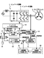
図1は、本発明の実施の形態1に係る圧縮機用電動機の制御装置の構成を示す図である。この圧縮機用電動機の制御装置は、コンバータ回路1、インバータ回路2、DCブラシレスモータ3、回転数・回転角度検出部10、圧縮開始位置検出部11、トルク制御パターン記憶部12、加算器13、比例・積分定数部14、切替スイッチ15、定数発生部16、乗算器17、インバータUVW波形制御部18、回転数変動幅検出部20、圧縮開始位置補正部21及び加算器22から構成されている。
【0016】
コンバータ回路1は、交流電源からの電力を直流電力に変換してインバータ回路2に供給する周知の回路である。インバータ回路2は、コンバータ回路1からの直流電力を、インバータUVW波形制御部18からの制御信号に応じて、3相の電力に変換し、DCブラシレスモータ3に供給する。DCブラシレスモータ3は、図示しない圧縮機を駆動する直流モータである。
【0017】
回転数・回転角度検出部10は、DCブラシレスモータ3の誘起電圧に基づいて、その回転数及び回転角度を検出する。具体的には、回転数・回転角度検出部10は、誘起電圧のゼロクロス点の間隔、つまり、誘起電圧の周期に基づいてDCブラシレスモータ3の回転数を検出すると共に、誘起電圧がゼロクロス点を通過する毎に回転角度が0°、90°、180°及び270°であることを検出する。この回転数・回転角度検出部10で検出された回転数は、加算器13及び回転数変動幅検出部20に送られ、回転角度は、圧縮開始位置検出部11及びインバータUVW波形制御部18に送られる。
【0018】
圧縮開始位置検出部11は、DCブラシレスモータ3に結合されている図示しない圧縮機が圧縮動作を開始する圧縮動作開始タイミングを検出する。圧縮機が圧縮動作を開始するときのDCブラシレスモータ3のロータの回転角度は予め機械的に決定されている。圧縮開始位置検出部11は、回転数・回転角度検出部10で検出されたDCブラシレスモータ3の回転角度が、予め決定されている回転角度になるタイミングを圧縮機の圧縮動作開始タイミングとして検出し、その旨を表す信号を加算器22に送る。
【0019】
加算器22は、圧縮開始位置検出部11からの圧縮動作開始タイミングを表す信号に、後述する圧縮開始位置補正部21からの補正値を加算し、新たな圧縮開始位置を算出する。この加算器22から出力される新たな圧縮開始位置を表す信号は、トルク制御パターン記憶部12に送られる。
【0020】
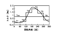
トルク制御パターン記憶部12は、トルク制御パターン偏差テーブルを記憶している。図2に示すトルクT1〜T6は、60゜の間隔で分割した6つの回転角度区間の各々における圧縮機の負荷トルクの平均値を示している。各負荷トルクT1〜T6の発生に必要なインバータ回路2の出力電圧は、演算やシミュレーションによって求めることができる。また、圧縮機が1回転する間での平均負荷トルクTavも演算やシミュレーションによって求めることができる。
【0021】
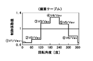
上記トルクT1〜T6の発生に必要なインバータ回路2の出力電圧をそれぞれV1〜V6、平均負荷トルクTavの発生に必要なインバータ回路2の出力電圧をVavとすると、トルク制御パターン偏差テーブルは、図3に示す関係、つまり、上記電圧V1〜V6の各々を電圧Vavで除算した制御係数値(V1/Vav)〜(V6/Vav)と、これらの制御係数値に対応する各回転角度間隔との関係を記憶している。このトルク制御パターン記憶部12に記憶されている制御計数値は、切替スイッチ15を経由して乗算器17に送られる。
【0022】
加算器13は、外部から回転数指令として与えられる圧縮機の目標回転数(DCブラシレスモータ3の目標回転数)と、回転数・回転角度検出部10で検出された圧縮機の実際の回転数との偏差(回転数偏差)を算出する。この加算器13から出力される回転数偏差は、比例・積分定数部14に送られる。
【0023】
比例・積分定数部14は、加算器13からの回転数偏差に比例・積分補償を施し、圧縮機の回転数偏差の平均値に対応する電圧Vavを平均電圧指令として出力する。この比例・積分定数部14から出力される平均電圧指令は、乗算器17に送られる。
【0024】
切替スイッチ15は、圧縮機の目標回転数が所定の低回転数域の回転数である場合にオンにされる。そして、オンにされた状態でトルク制御パターン記憶部12の出力を選択する。一方、オフにされた状態では、定数発生部16で発生された制御係数値「1」を選択して出力する。
【0025】
乗算器17は、比例・積分定数部14から出力される平均電圧指令に切替スイッチ15で選択された制御係数値を乗算し、その乗算結果を電圧指令としてインバータUVW波形制御部18に送る。
【0026】
インバータUVW波形制御部18は、PWM信号生成機能を有し、回転数・回転角度検出部10によって検出された回転角度と乗算器17からの電圧指令とに基づいて、該電圧指令をUVW電圧制御信号に変換する。このUVW電圧制御信号は、インバータ回路2に送られる。
【0027】
回転数変動幅検出部20は、回転数・回転角度検出部10で検出された回転数に基づいて、1回転中の最大回転数と最小回転数との差を示す回転数変動幅r1を検出する。この検出された回転数変動幅r1は、圧縮開始位置補正部21に送られる。
【0028】
圧縮開始位置補正部21は、回転数変動幅検出部20からの回転数変動幅r1に基づいて、圧縮開始位置検出部11で検出された圧縮開始位置を補正するための補正値を発生する。この発生された補正値は、加算器22に送られる。この圧縮開始位置補正部21から出力される補正値は、図示しない固定信号をアクティブにすることにより固定できるように構成されている。
【0029】
次に、以上のように構成される本発明の実施の形態1に係る圧縮機用電動機の制御装置の動作を説明する。
【0030】
先ず、圧縮機の圧縮開始位置を補正する動作を説明する。この場合、DCブラシレスモータ3を一定負荷且つ一定回転数で回転させる。一定負荷の条件としては、一定回転数(或る周波数)で負荷が安定するまでの待機時間を採用することができる。
【0031】
この状態で、回転数・回転角度検出部10は、DCブラシレスモータ3の回転数を検出し、回転数変動幅検出部20に送る。回転数変動幅検出部20は、受け取った回転数に基づいて、回転数変動幅r1を検出し、圧縮開始位置補正部21に送る。これにより、圧縮開始位置補正部21は、回転数変動幅r1が最小となるような補正値を生成し、加算器22に送る。
【0032】
ここで、圧縮開始位置補正部21において、回転数変動幅r1が最小となるような補正値は、以下の手順で求めることができる。即ち、圧縮開始位置補正部21は、複数の補正値を加算器22に送り、回転数変動幅検出部20で検出された補正値毎の回転数変動幅を収集する。そして、収集された回転変動数幅の中の最も小さいものに対応する補正値を、回転数変動幅r1が最小となる補正値として決定する。以後は固定信号がアクティブにされ、圧縮開始位置補正部21は、この決定された補正値を固定的に出力する。圧縮機のステータの組み込み角度は、その圧縮機の構造によって固有に決定されので、上述した動作は、圧縮機を運転中に1回だけ実行すればよい。
【0033】
次に、圧縮機用電動機の制御装置の動作を説明する。この場合、上述した動作によって圧縮開始位置補正部21は回転数変動幅r1が最小となる補正値を出力するように設定されているものとする。
【0034】
今、目標回転数が低回転数域の回転数よりも高い回転数に設定されているとすると、切替スイッチ15がオフにされる。その結果、乗算器17において比例・積分定数部14の出力に、定数発生部16からの係数「1」が乗算される。従って、比例・積分定数部14の出力がインバータUVW波形制御部18に直接送られる。
【0035】
即ち、比例・積分定数部14からは、加算器13から出力される回転数偏差を平均した平均電圧指令が出力されるので、切替スイッチ15がオフにされた状態では、この平均電圧指令が電圧指令としてインバータUVW波形制御部18に直接入力される。これにより、インバータUVW波形制御部18は、平均電圧指令に対応するUVW電圧制御信号をインバータ回路2に送り、その結果、DCブラシレスモータ3が平均トルクTavを発生するように駆動される。
【0036】
次に、目標回転数が低回転数域の回転数に設定されている場合は、切替スイッチ15がオンにされる。従って、乗算器17において、比例・積分定数部14から出力される平均電圧指令にトルク制御パターン記憶部12から出力されるトルク制御パターンが乗算される。
【0037】
圧縮開始位置検出部11は、予め決定されている回転角度になるタイミングを圧縮機の圧縮動作開始タイミングとして検出し、その旨を表す信号を加算器22に送る。一方、圧縮開始位置補正部21は、上記固定された補正値を加算器22に送る。加算器22は、上記圧縮開始位置検出部11からの信号と圧縮開始位置補正部21からの補正値を表す信号とを加算し、トルク制御パターン記憶部12に送る。その結果、圧縮機の回転角度が正確な制御開始角度になるタイミングで、トルク制御パターン記憶部12の記憶内容の読み出しが開始される。これにより、トルク制御パターン偏差テーブルから、回転角度が制御開始角度から60°増す度にトルク制御パターン偏差α、つまり、図3に示す制御係数値V1/Vav、V2/Vav、・・・V6/Vavが順次出力される。
【0038】
上述したように、比例・積分定数部14は平均トルクTavに対応する電圧Vavを出力し、トルク制御パターン記憶部12はトルク制御パターンαを出力するので、乗算器17からは電圧V1、V2、・・・V6が新たな電圧指令として順次出力されることになる。この結果、DCブラシレスモータ3のトルクは、圧縮機が1回転する間、図2に示すように、T1,T2,・・・T6という態様で変化することになる。つまり、負荷トルクの大きさに応じて且つ負荷トルクの変動に追従して変化することになる。
【0039】
以上説明した本発明の実施の形態1に係る圧縮機用電動機の制御装置によれば、圧縮開始位置検出部11で検出された圧縮開始位置を、回転数振動幅が最も小さくなるように補正した後に圧縮機の運転を行うので、圧縮機製造時において、DCブラシレスモータ3のステータを圧縮機に組み込む際に、組み込み角度にバラツキが生じて組み込み誤差が発生しても、回転振動を抑えることができる。
【0040】
(実施の形態2)
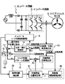
本発明の実施の形態2に係る圧縮機用電動機の制御装置は、上述した実施の形態1に係る圧縮機用電動機の制御装置に負荷状態検出部30が追加されて構成されている。
【0041】
負荷状態検出部30は、インバータUVW波形制御部18で生成された一定回転数におけるPWM信号を入力する。そして、入力されたPWM信号のデューティ比が所定範囲以内であるかどうかを調べ、所定範囲内であることを検出すると、一定回転数で一定負荷状態にあることを表す一定負荷信号を圧縮開始位置補正部21に送る。
【0042】
圧縮開始位置補正部21は、負荷状態検出部30から一定負荷信号が送られてきた場合に、一定負荷の条件が成立したものとして、実施の形態1で説明した圧縮機の圧縮開始位置を補正する動作を行う。
【0043】
この実施の形態2に係る圧縮機用電動機の制御装置によれば、負荷状態検出部30によって一定負荷の条件が成立したかどうかを判断することができるので、負荷が安定するまでの時間として所定の待機時間が経過するのを待つ必要がない。従って、圧縮開始位置の補正値を迅速に決定することができる。
【0044】
【発明の効果】
以上詳述したように、本発明によれば、圧縮機の圧縮開始位置に誤差が生じても回転振動を抑えることができる圧縮機用電動機の制御装置を提供できる。
【0045】
より詳しくは、本発明に係る圧縮機用電動機の制御装置によれば、圧縮開始位置検出部で検出された圧縮開始位置を、回転数振動幅が最も小さくなるように補正した後に圧縮機の運転を行うので、圧縮機製造時において、電動機のステータを圧縮機に組み込む際に、組み込み角度にバラツキが生じて組み込み誤差が発生しても、回転振動を抑えることができる。
【0046】
また、負荷状態検出部によって負荷状態が一定であるかどうかを判断することができるので、負荷が安定するまでの時間として所定の待機時間が経過するのを待つ必要がなく、圧縮開始位置の補正値を迅速に決定することができる。
【図面の簡単な説明】
【図1】本発明の実施の形態1に係る圧縮機用電動機の制御装置の構成を示す図である。
【図2】本発明の実施の形態1に係る圧縮機用電動機の制御装置における負荷トルクの変動パターンに対する駆動トルクの変化パターンを示す図である。
【図3】本発明の実施の形態1に係る圧縮機用電動機の制御装置におけるトルク制御パターン偏差テーブルの記憶内容を示す図である。
【図4】本発明の実施の形態2に係る圧縮機用電動機の制御装置の構成を示す図である。
【符号の説明】
1 コンバータ回路
2 インバータ回路
3 DCブラシレスモータ
10 回転数・回転角度検出部
11 圧縮開始位置検出部
12 トルク制御パターン記憶部
13 加算器
14 比例・積分定数部
15 切替スイッチ
16 定数発生部
17 乗算器
18 インバータUVW波形制御部
20 回転数変動幅検出部
21 圧縮開始位置補正部
22 加算器[0001]
TECHNICAL FIELD OF THE INVENTION
The present invention relates to a control device for a motor for a compressor, and more particularly to a technique for reducing vibration of a motor driving the compressor.
[0002]
[Prior art]
Conventionally, a control device for controlling an electric motor for driving a compressor has been known. As such a control device, for example, Japanese Patent Application Laid-Open No. 2001-295969 discloses a "control device for a compressor motor" that can reduce rotational vibration generated due to imbalance between the drive torque and the load torque of the compressor. Has been disclosed.
[0003]
The control device for the compressor motor includes a storage unit in which a coefficient that changes in a pattern corresponding to a change pattern of the load torque during one rotation of the compressor is stored in advance as a torque control pattern. Then, the rotation angle of the motor is detected, a coefficient corresponding to the detected rotation angle is read from the storage means, and the read coefficient is multiplied by an average voltage command corresponding to the rotation speed deviation of the motor to obtain a new voltage command. Is generated, and the motor is driven based on the generated new voltage command so that the torque of the motor follows a change in the load torque during one rotation.
[0004]
[Problems to be solved by the invention]
The compressor motor control device described above detects the compression start position of the compressor and starts reading the torque control pattern based on the detected compression start position. Then, a new voltage command is generated based on the torque control pattern to drive the motor.
[0005]
However, since the compression start position is determined mechanically, when the stator of the motor is incorporated into the compressor during the manufacture of the compressor, a variation occurs in the installation angle and an installation error occurs. As a result, a displacement occurs at the compression start position, causing rotational vibration.
[0006]
Therefore, an object of the present invention is to provide a control device for a compressor motor that can suppress rotational vibration even if an error occurs in the compression start position of the compressor.
[0007]
[Means for Solving the Problems]
The means for solving the problem will be described below using the numbers and symbols used in [Embodiments of the Invention]. These numbers and symbols are added to clarify the correspondence between the description of [Claims] and the description of [Embodiments of the Invention]. It should not be used to interpret the technical scope of the described invention.
[0008]
In order to achieve the above object, the control device for a motor for a compressor according to the present invention provides an average voltage command corresponding to a rotation speed deviation of the motor (3) for driving the compressor during one rotation of the motor (3). A control device for a motor for a compressor for controlling a drive voltage of a motor (3) by multiplying a torque control pattern that changes in accordance with a change pattern of a load torque of the compressor, and detects a compression start position of the compressor. A compression start position detection unit (11), a rotation speed fluctuation width detection unit (20) for detecting a fluctuation width of the rotation speed of the electric motor (3), and a compression start position detected by the compression start position detection unit (11). A correction unit (21, 22) for correcting based on the fluctuation width of the rotation speed detected by the rotation speed fluctuation detection unit (20), and a torque control pattern storage unit (12) storing the torque control pattern. And the correction unit (21, 2 The driving voltage of the electric motor (3) is controlled by reading out the torque control pattern from the torque control pattern storage unit (12) at the timing of the compression start position corrected in the above) and multiplying the torque control pattern by the average voltage command. .
[0009]
According to the control device for the compressor motor, the compressor is operated after the compression start position detected by the compression start position detection unit (11) is corrected so that the rotation frequency oscillation width is minimized. When manufacturing the compressor, when the stator of the electric motor (3) is installed in the compressor, even if the installation angle varies and an installation error occurs, rotational vibration can be suppressed.
[0010]
In the control device for a motor for a compressor according to the present invention, the correction units (21, 22) start compression in which a correction value is generated based on the rotation speed fluctuation width from the rotation speed fluctuation width detection unit (20). The compression start position is corrected by adding the correction values generated by the position correction unit (21) and the compression start position correction unit (21) to the compression start position detected by the compression start position detection unit (11). And an adder (22).
[0011]
Further, in the control device for a motor for a compressor according to the present invention, the compression start position correction unit (21) includes a correction value generated by the compression start position correction unit (21) when the electric motor (3) is under a constant load. Can be added to the compression start position detected by the compression start position detection unit (11).
[0012]
Furthermore, the control device for a compressor motor according to the present invention further includes a load state detection unit (30) for detecting a load state of the motor (3), and the compression start position correction unit (21) includes a load state detection unit. When the load state detected in (30) is constant, the correction value generated by the compression start position correction unit (21) is added to the compression start position detected by the compression start position detection unit (11). It can be configured as follows.
[0013]
According to this configuration, it is possible to determine whether the load state is constant by the load state detection unit (30). Therefore, it is necessary to wait for a predetermined standby time to elapse as a time until the load is stabilized. Therefore, the correction value of the compression start position can be quickly determined.
[0014]
BEST MODE FOR CARRYING OUT THE INVENTION
Hereinafter, embodiments of the present invention will be described in detail with reference to the drawings. The control device for a compressor motor according to the present embodiment is an improvement of the control device for a compressor motor disclosed in Japanese Patent Application Laid-Open No. 2001-29569. Therefore, in the following, the description of the overlapping portion will be simplified, and therefore, please refer to JP-A-2001-29569 as needed.
[0015]
(Embodiment 1)
FIG. 1 is a diagram showing a configuration of a control device for a compressor electric motor according to
[0016]
[0017]
The rotation speed / rotation angle detection unit 10 detects the rotation speed and rotation angle based on the induced voltage of the DC brushless motor 3. Specifically, the rotation speed / rotation angle detection unit 10 detects the rotation speed of the DC brushless motor 3 based on the interval between the induced voltage zero-cross points, that is, the period of the induced voltage, and detects the induced voltage at the zero-cross point. Each time it passes, it detects that the rotation angles are 0 °, 90 °, 180 ° and 270 °. The rotation speed detected by the rotation speed / rotation angle detection unit 10 is sent to the
[0018]
The compression
[0019]
The
[0020]
The torque control
[0021]
Assuming that the output voltages of the
[0022]
The
[0023]
The proportional / integral
[0024]
The
[0025]
The multiplier 17 multiplies the average voltage command output from the proportional / integral
[0026]
The inverter UVW
[0027]
The rotation speed fluctuation
[0028]
The compression start
[0029]
Next, the operation of the control device for a compressor motor according to
[0030]
First, the operation of correcting the compression start position of the compressor will be described. In this case, the DC brushless motor 3 is rotated at a constant load and a constant rotation speed. As the condition of the constant load, a standby time until the load is stabilized at a constant rotation speed (a certain frequency) can be adopted.
[0031]
In this state, the rotation speed / rotation angle detection unit 10 detects the rotation speed of the DC brushless motor 3 and sends it to the rotation speed fluctuation
[0032]
Here, in the compression start
[0033]
Next, the operation of the control device for the compressor motor will be described. In this case, it is assumed that the compression start
[0034]
Assuming that the target rotation speed is set to a rotation speed higher than the rotation speed in the low rotation speed range, the
[0035]
That is, since the proportional / integral
[0036]
Next, when the target rotation speed is set to the rotation speed in the low rotation speed range, the
[0037]
The compression start
[0038]
As described above, since the proportional / integral
[0039]
According to the control device for a compressor motor according to the first embodiment of the present invention described above, the compression start position detected by the compression start
[0040]
(Embodiment 2)
The control device for a compressor motor according to the second embodiment of the present invention is configured by adding a load
[0041]
The load
[0042]
The compression start
[0043]
According to the control device for a compressor motor according to the second embodiment, the load
[0044]
【The invention's effect】
As described in detail above, according to the present invention, it is possible to provide a control device for a compressor motor that can suppress rotational vibration even if an error occurs in the compression start position of the compressor.
[0045]
More specifically, according to the compressor motor control device of the present invention, after the compression start position detected by the compression start position detection unit is corrected so that the rotation frequency vibration width is minimized, the operation of the compressor is started. Therefore, when manufacturing the compressor, when the stator of the electric motor is installed in the compressor, even if the installation angle varies and an installation error occurs, the rotational vibration can be suppressed.
[0046]
Further, since the load state detector can determine whether the load state is constant, there is no need to wait for a predetermined standby time to elapse before the load is stabilized, and the compression start position can be corrected. The value can be determined quickly.
[Brief description of the drawings]
FIG. 1 is a diagram showing a configuration of a control device for a motor for a compressor according to a first embodiment of the present invention.
FIG. 2 is a diagram illustrating a change pattern of a drive torque with respect to a change pattern of a load torque in a control device for a compressor motor according to a first embodiment of the present invention.
FIG. 3 is a diagram showing stored contents of a torque control pattern deviation table in the compressor motor control device according to the first embodiment of the present invention.
FIG. 4 is a diagram showing a configuration of a control device for a compressor motor according to a second embodiment of the present invention.
[Explanation of symbols]
DESCRIPTION OF
Claims (4)
前記圧縮機の圧縮開始位置を検出する圧縮開始位置検出部と、
前記電動機の回転数の変動幅を検出する回転数変動幅検出部と、
前記圧縮開始位置検出部で検出された圧縮開始位置を、前記回転数変動幅検出部で検出された回転数の変動幅に基づいて補正する補正部と、
前記トルク制御パターンを記憶したトルク制御パターン記憶部、とを備え、
前記補正部で補正された圧縮開始位置のタイミングで前記トルク制御パターン記憶部から前記トルク制御パターンを読み出して前記平均電圧指令に乗算することにより前記電動機の駆動電圧を制御する圧縮機用電動機の制御装置。The driving voltage of the motor is obtained by multiplying an average voltage command corresponding to a rotational speed deviation of the motor driving the compressor by a torque control pattern that changes in accordance with a change pattern of the load torque during one rotation of the motor. A control device for a compressor electric motor to be controlled,
A compression start position detection unit that detects a compression start position of the compressor,
A rotation speed fluctuation width detection unit that detects a fluctuation width of the rotation speed of the electric motor,
A correction unit that corrects the compression start position detected by the compression start position detection unit based on the fluctuation width of the rotation speed detected by the rotation speed fluctuation width detection unit,
A torque control pattern storage unit storing the torque control pattern,
A control of a motor for a compressor that controls the drive voltage of the motor by reading the torque control pattern from the torque control pattern storage unit at the timing of the compression start position corrected by the correction unit and multiplying the torque control pattern by the average voltage command. apparatus.
前記回転数変動幅検出部からの回転数の変動幅に基づいて補正値を発生する圧縮開始位置補正部と、
前記圧縮開始位置補正部で発生された補正値を、前記圧縮開始位置検出部で検出された圧縮開始位置に加算することにより圧縮開始位置を補正する加算器、
とを備えた請求項1に記載の圧縮機用電動機の制御装置。The correction unit,
A compression start position correction unit that generates a correction value based on the fluctuation width of the rotation speed from the rotation speed fluctuation width detection unit,
An adder for correcting the compression start position by adding a correction value generated by the compression start position correction unit to the compression start position detected by the compression start position detection unit;
The control device for a motor for a compressor according to claim 1, comprising:
前記電動機が一定負荷の状態で、前記圧縮開始位置補正部で発生された補正値を、前記圧縮開始位置検出部で検出された圧縮開始位置に加算する、請求項2に記載の圧縮機用電動機の制御装置。The compression start position correction unit,
The motor for a compressor according to claim 2, wherein a correction value generated by the compression start position correction unit is added to a compression start position detected by the compression start position detection unit when the motor is under a constant load. Control device.
前記圧縮開始位置補正部は、前記負荷状態検出部で検出された負荷状態が一定である状態で、前記圧縮開始位置補正部で発生された補正値を、前記圧縮開始位置検出部で検出された圧縮開始位置に加算する、請求項3に記載の圧縮機用電動機の制御装置。Further comprising a load state detection unit for detecting a load state of the electric motor,
The compression start position correction unit detects a correction value generated by the compression start position correction unit in a state where the load state detected by the load state detection unit is constant, and the compression start position detection unit detects the correction value. The control device for a compressor electric motor according to claim 3, wherein the control is added to a compression start position.
Priority Applications (1)
| Application Number | Priority Date | Filing Date | Title |
|---|---|---|---|
| JP2002171578A JP2004019461A (en) | 2002-06-12 | 2002-06-12 | Control device for compressor motor |
Applications Claiming Priority (1)
| Application Number | Priority Date | Filing Date | Title |
|---|---|---|---|
| JP2002171578A JP2004019461A (en) | 2002-06-12 | 2002-06-12 | Control device for compressor motor |
Publications (1)
| Publication Number | Publication Date |
|---|---|
| JP2004019461A true JP2004019461A (en) | 2004-01-22 |
Family
ID=31171400
Family Applications (1)
| Application Number | Title | Priority Date | Filing Date |
|---|---|---|---|
| JP2002171578A Withdrawn JP2004019461A (en) | 2002-06-12 | 2002-06-12 | Control device for compressor motor |
Country Status (1)
| Country | Link |
|---|---|
| JP (1) | JP2004019461A (en) |
Cited By (2)
| Publication number | Priority date | Publication date | Assignee | Title |
|---|---|---|---|---|
| US7525270B2 (en) | 2005-06-27 | 2009-04-28 | Denso Corporation | Motor control apparatus |
| WO2013108794A1 (en) | 2012-01-17 | 2013-07-25 | サントリーホールディングス株式会社 | Novel glycosyltransferase gene and use thereof |
-
2002
- 2002-06-12 JP JP2002171578A patent/JP2004019461A/en not_active Withdrawn
Cited By (3)
| Publication number | Priority date | Publication date | Assignee | Title |
|---|---|---|---|---|
| US7525270B2 (en) | 2005-06-27 | 2009-04-28 | Denso Corporation | Motor control apparatus |
| DE102006028331B4 (en) | 2005-06-27 | 2019-02-14 | Denso Corporation | Motor controller |
| WO2013108794A1 (en) | 2012-01-17 | 2013-07-25 | サントリーホールディングス株式会社 | Novel glycosyltransferase gene and use thereof |
Similar Documents
| Publication | Publication Date | Title |
|---|---|---|
| US6828752B2 (en) | Driving equipment and semiconductor equipment for alternating-current motor | |
| JP5984524B2 (en) | Motor control device | |
| US11088646B2 (en) | Motor driving control device and motor driving control method | |
| JP4050489B2 (en) | Motor control method | |
| JP2008172948A (en) | Brushless motor control device | |
| JP2006149097A (en) | Motor control device | |
| JP2020005472A (en) | Control apparatus of dynamo-electric motor | |
| JP7290434B2 (en) | MOTOR DRIVE CONTROL DEVICE AND MOTOR DRIVE CONTROL METHOD | |
| JP4329842B2 (en) | Fan motor control device and air conditioner | |
| JP2013081320A (en) | Motor drive unit | |
| JP2000232797A (en) | Drive device for brushless motor | |
| JP2004019461A (en) | Control device for compressor motor | |
| WO2019021663A1 (en) | Motor drive control device and motor drive control method | |
| JP2000188891A (en) | Method and device for driving brushless motor | |
| JP2007267576A (en) | Brushless DC motor control device | |
| JP3544338B2 (en) | Control device for compressor motor | |
| JP4068392B2 (en) | Motor control device | |
| JP2001224198A (en) | Starting method for permanent magnet synchronous motor | |
| JP2004023818A (en) | Motor controller | |
| JPH08126377A (en) | Motor control method | |
| JP2002354873A (en) | Motor drive | |
| JP5223238B2 (en) | Brushless motor control device | |
| JP3924140B2 (en) | Gas turbine plant and operation method thereof | |
| KR100594387B1 (en) | Motor Control Device and Method | |
| JP2007020345A (en) | Brushless motor controller |
Legal Events
| Date | Code | Title | Description |
|---|---|---|---|
| A300 | Withdrawal of application because of no request for examination |
Free format text: JAPANESE INTERMEDIATE CODE: A300 Effective date: 20050906 |