JP2004058626A - Image processing method and image processing apparatus - Google Patents
Image processing method and image processing apparatus Download PDFInfo
- Publication number
- JP2004058626A JP2004058626A JP2002224166A JP2002224166A JP2004058626A JP 2004058626 A JP2004058626 A JP 2004058626A JP 2002224166 A JP2002224166 A JP 2002224166A JP 2002224166 A JP2002224166 A JP 2002224166A JP 2004058626 A JP2004058626 A JP 2004058626A
- Authority
- JP
- Japan
- Prior art keywords
- patch
- color material
- data
- total
- usage
- Prior art date
- Legal status (The legal status is an assumption and is not a legal conclusion. Google has not performed a legal analysis and makes no representation as to the accuracy of the status listed.)
- Pending
Links
Images






Landscapes
- Facsimile Image Signal Circuits (AREA)
- Color Image Communication Systems (AREA)
- Color, Gradation (AREA)
- Image Processing (AREA)
- Fax Reproducing Arrangements (AREA)
Abstract
【課題】インクやトナーなど色材の過剰な付与が生じないようにして正確なパッチを記録し精度の高い測色結果を得ることを可能とする画像処理方法を提供する。
【解決手段】パッチを構成するY、M、C、Kの基本4色の組み合わせを決める(S1001)。次に、決定された基本4色の組み合わせそれぞれについて、各インクの色材使用量を参照しながらその組合せの色材総使用量を計算する(S1002)。上記算出された各組合せごとの色材総使用量と、同様に予め計算された最大色材総使用量を比較し、その組合せの色材総使用量が最大色材総使用量を超えるか否かを判断をする(S1003)。そして、最大色材総使用量を超えると判断された組合せについて、最大色材総使用量を超える分の量を計算し、さらに、用いるパッチデータの圧縮率を境界情報として計算する(S1004)。そして、この圧縮率で全てのパッチのデータについて均一に圧縮が行ない、パッチデータを作成する(S1005)。
【選択図】 図6Provided is an image processing method capable of recording an accurate patch and obtaining a highly accurate color measurement result without excessively applying a color material such as ink or toner.
A combination of four basic colors of Y, M, C, and K forming a patch is determined (S1001). Next, for each of the determined combinations of the four basic colors, the total color material usage of the combination is calculated with reference to the color material usage of each ink (S1002). Compare the calculated total color material usage for each combination with the maximum color material total usage similarly calculated in advance, and determine whether the total color material usage for the combination exceeds the maximum color material total usage. Is determined (S1003). Then, for the combination determined to exceed the maximum color material total usage, the amount exceeding the maximum color material total usage is calculated, and the compression ratio of the used patch data is calculated as boundary information (S1004). Then, data of all patches is uniformly compressed at this compression ratio, and patch data is created (S1005).
[Selection] Fig. 6
Description
【0001】
【発明の属する技術分野】
本発明は、画像処理方法および画像処理装置に関し、詳しくは、インクジェットプリンタなど画像出力装置で用いられるインク等、色材のデータ生成に係る変換関係を、パッチを用いて求める際のパッチデータ生成処理に関するものである。
【0002】
【従来の技術】
一般に、プリンタなどの画像出力装置においてカラー画像をプリント出力する場合、Y(イエロー)、M(マゼンタ)、C(シアン)およびK(ブラック)の4つの色材が用いられる。例えば、インクジェットプリンタではY、M、C、Kのインクが用いられ、また、電子写真方式の複写機やプリンタではY、M、C、Kのトナーが用いられる。
【0003】
画像出力装置で用いられるこれら色材によって実現される色空間は、通常元の画像データとは異なる色空間を有しており、そのため、画像データに基づいて色材データを生成する画像処理では元の画像データが示す色や階調を忠実にもしくは所望の色等を再現すべく様々な画像処理方法が提案されている。
【0004】
その一つとして、例えば、特開平2−136848号公報には、上記色材データ生成処理の一環として行なわれる100%UCR(下色除去処理)の色再現性の問題を改善した画像処理方法が記載されている。ここでは、元の画像データが示すある色を表わすことができるY、M、C、Kのいくつかの組合せのうち、Kが最大である組合せをY、M、C、Kの組合せとして定める。これによれば、100%UCRではY、M、CのうちKによって置換された最小濃度の色の値が0になるのに対し、そのような0の値を含まないY、M、C、Kの組合せを存在させることができ、彩度や濃度の低下のない画像出力を行なうことができるとされている。さらに、特開平6−242523号公報には、上記公報に記載の画像処理に対して、Y、M、C、Kの色材による再現範囲、出力画像における擬似輪郭、補間精度などを考慮したKの設定を行なうことにより、さらに再現性の向上を図った画像処理方法が記載されている。
【0005】
ところで、上述の色修正にかかる画像処理は、通常、その色修正を実現するデータを有したルックアップテーブル(LUT)と補間演算を用いて行なわれる。そして、このテーブルの内容は、色材Y、M、C、Kの複数の組合せについてパッチを記録し、それを測色することによって求められる。具体的には、各パッチを構成するY、M、C、Kの信号値が8ビットで表わされる場合、例えば、各色の256値を8等分した0,32,64,…,223,255の値の組合せである4096個の色についてパッチを記録し、その測色結果に基づいて所定の目標(ターゲット)となる色を再現するY、M、C、Kの組合せを求め、これをテーブルデータとするものである。
【0006】
【発明が解決しようとする課題】
しかしながら、上記のようなプリンタなどの画像出力装置における再現性の向上を図った画像処理がなされたとしても、プリンタなどにおける実際のプリント(記録)が色材と記録用紙との関係で不適切となり、結果として所望の画像再現ができない場合がある。
【0007】
上記二つの公報に記載の処理は、基本的に、Y、M、C、Kの4つの色材を同時に用いる処理であるため、用いる色材の総量が多くなる傾向にある。特に、低い明度において彩度の高い色を再現しようとする場合はそれぞれの色材の信号値が高くなり、使用するそれぞれの色材の量が多くなる。この場合、インクジェットプリンタなどでは、記録用紙のインク吸収特性によってはインクを十分に吸収できずインクの溢れや滲みを生じ、濃度などが正確に実現されないことがある。また、トナーを使用する電子写真方式のプリンタでは、記録用紙のトナー付着特性によってはトナーが十分に記録紙に定着できず、同様に濃度の正確な実現ができないことがある。その結果、色材データを生成する画像処理において良好な画像再現性が図られていたとしても、実際に記録を行なった結果においては正確な画像再現ができない場合がある。
【0008】
以上のような画像処理に基づいて上述したパッチのデータを生成して記録する場合、同様の問題が生じ得る。特に、パッチの記録では、通常の記録では禁止されているようなデータのパッチが記録される場合があり、問題はより顕著となる。例えば、1つの色材の最大量を100%とし、全ての色材が最大量を用いる信号値である場合は、記録用紙に付与される総色材量は400%となる。このように4つの色材がそれらの最大量近傍で用いられる場合には、インクジェットプリンタなどでは、記録用紙が重畳的に付与される4種類のインクを吸収できず、また、トナーを使用する電子写真方式のプリンタでは4色のトナーが記録紙に適切に定着できず、その結果、正確なパッチの再現ができない。
【0009】
このようにパッチが正確に記録されていない場合、その測色値は当然にそれを記録したプリンタの記録特性を反映したものとはならず、正確なテーブルを作成することができない。また、結果として、パッチの記録や測色のための操作、処理がその不正確なパッチの分だけ無駄なものとなる。
【0010】
なお、以上の色材使用量の問題は、記録用紙と色材との間の、吸収性や付着性などの相対的な特性によって定まることはもちろんである。従って、総色材使用量が例えば300%であっても、用いる記録用紙によっては同様の問題を生じ得るものであり、また、上述した100%UCRに基づいて得られる総色材使用量であっても記録用紙との相対的な関係で同様な問題を生じる可能性がある。
【0011】
本発明は、上述の問題を解決するためになされたものであり、その目的とするところは、インクやトナーなど色材の過剰な付与が生じないようにして正確なパッチを記録し精度の高い測色結果を得ることを可能とする画像処理方法および画像処理装置を提供することにある。
【0012】
【課題を解決するための手段】
そのために、本発明では、複数種類の色材を用いて画像出力を行う画像出力装置の出力特性を調整するために用いられるパッチを当該画像出力装置から出力するためのデータを生成する画像処理方法であって、パッチを出力するために用いられ得る複数種類の色材データの組合せであって、複数のパッチそれぞれについて定められた第1パッチデータと、複数の色材それぞれの、前記画像出力装置でパッチを出力する際に用いられる記録媒体に対する付着特性を考慮して定められる最大色材総使用量とを用意し、前記第1パッチデータにおけるパッチごとの、複数種類の色材データの組合せに基づき、当該パッチを出力するための当該複数種類の色材の総使用量を求め、パッチごとにその総色材使用量と前記最大色材総使用量とを比較し、該パッチごとの比較に基づき、前記第1パッチデータに対して各パッチの総色材使用量が前記最大色材総使用量以下となる処理を行い、第2パッチデータを生成する、ステップを有したことを特徴とする。
【0013】
また、複数種類の色材を用いて画像出力を行う画像出力装置の出力特性を調整するために用いられるパッチを当該画像出力装置から出力するためのデータを生成する画像処理装置であって、パッチを出力するために用いられ得る複数種類の色材データの組合せであって、複数のパッチそれぞれについて定められた第1パッチデータと、複数の色材それぞれの、前記画像出力装置でパッチを出力する際に用いられる記録媒体に対する付着特性を考慮して定められる最大色材総使用量とを保持する手段と、前記第1パッチデータにおけるパッチごとの、複数種類の色材データの組合せに基づき、当該パッチを出力するための当該複数種類の色材の総使用量を求める総使用量計算手段と、パッチごとにその総色材使用量と前記最大色材総使用量とを比較し、該パッチごとの比較に基づき、前記第1パッチデータに対して各パッチの総色材使用量が前記最大色材総使用量以下となる処理を行い、第2パッチデータを生成するパッチデータ生成手段と、を具えたことを特徴とする。
【0014】
以上の構成によれば、パッチを出力するために用いられ得る複数種類の色材データの組合せであって、複数のパッチそれぞれについて定められた第1パッチデータが用意され、この第1パッチデータに対して各パッチの総色材使用量が、画像出力装置でパッチを出力する際に用いられる記録媒体に対するインク吸収性やトナー付着性などの色材付着特性を考慮して定められる最大色材総使用量以上のパッチがあるときは、全てのパッチについて最大色材総使用量以下となる処理を行い第2パッチデータを生成するので、このデータに基づいて出力されたパッチは、インク溢れやトナーが適切に付着しないなどのパッチ出力不良を生じることを防止できる。
【0015】
【発明の実施の形態】
以下、図面を参照して本発明の実施形態を詳細に説明する。
(第1の実施形態)
図1は本発明の一実施形態にかかるカラープリンタの画像処理構成を示すブロック図であり、パッチを形成しその測色結果に基づいてテーブルデータを生成する処理(以下、「色分解処理」ともいう)を示すものである。本構成は、以下で説明されるように具体的にはホストコンピュータの例えばプリンタドライバによって実行される処理を示しているが、これらの処理がプリンタ等の画像出力装置側で行われてもよく、あるいはホスト装置と画像出力装置がこれらの処理を分担してもよく、本発明の適用はこれらのいずれの形態にも適用できることは以下の説明からも明らかである。
【0016】
図1に示すように、色分解処理では、色材使用量計算101によって、本実施形態のプリンタで用いるY、M、C、K4つのインクそれぞれの色材使用量および最大色材総使用量を計算する。
【0017】
色材使用量は、Y、M、C、Kのインクそれぞれについて求められるものであり、本実施形態では、それぞれの8ビットが表わす信号値0〜255について0%〜100%として比例関係で計算されるものである。ここで使用量「A」%とは、基本的に、その8ビット信号が2値化等の量子化がなされてプリンタにおけるインク吐出データとされ記録用紙に記録が行われるとき、対応する画素に平均して「A」%の確率でインクドットが形成されることを意味する。しかし、Y、M、C、K各インクの浸透性などを考慮し、インクによっては、信号値0〜255について、例えば、0%〜80%として比例関係で計算してもよい。
【0018】
次に、最大色材総使用量は、上記のように計算した、例えばインクCの色材使用量を100%(すなわち、最大信号値255のときの使用量が100%)としたとき、本プリンタで用いる記録媒体の種類、すなわち用いる記録媒体が、普通紙、コート紙、OHP用紙などのいずれかであるかについて情報を得、これ基づいて記録媒体に上記インクCを最大何%まで吸収できるかが計算されるものである。
【0019】
出力特性パッチ画像作成102は、色材使用量計算手段101で算出された最大色材総使用量と4つのインクY、M、C、Kの個々の色材使用量を用いて、図5、図6にて詳細に後述されるように、インクのオーバーフロー(吸収できない状態)が起きない範囲で記録できるパッチのデータ作成する。この記録されたパッチは、測色されてプリンタの再現可能なL*a*b*で表される色空間のデータとして求められる。なお、この測色の表色系は上例に限られないことはもちろんであり、RGB等の他の表色系であってもよい。
【0020】
ターゲット設定103は、上記パッチの測色データに基き、Y(イエロー)、M(マゼンタ)、C(シアン)、R(レッド)、G(グリーン)およびB(ブルー)の6色相それぞれについて、彩度を最大とするターゲットを作成する。そして、基本4色色分解104は、各色相において彩度が最大になるという条件(上記のターゲット)でY、M、C、Kの組合わせを決定し、それらを色修正にかかる色分解テーブルの内容とする。
【0021】
図2は、上記画像処理を実行す具体的なる画像処理システムを示す図である。
【0022】
同図において、201は画像信号入力装置としての分光光度計を示し、202はコンピュータシステムとしてのパーソナルコンピュータを示す。パーソナルコンピュータ202は、分光光度計201によって読み取られた画像信号を入力し、編集、保管することができ、また、編集等された画像信号情報をディスプレイ203によって表示したり、画像出力装置としてのプリンタ204によってプリント出力することもできる。また、313は、ユーザが上記のパーソナルコンピュータ202の処理、制御に対する指示入力などを行うためのキーボードおよびマウスを示す。
【0023】
図3は、図2に示したシステムおける特にパーソナルコンピュータ202の主要な要素を示すブロック図である。
【0024】
同図において、301は、マウスおよびキーボード313と信号の授受を行うためのインターフェース(I/F)を示し、302は、同様に分光光度計201等の画像入力機器との間のインターフェース(I/F)を示す。
【0025】
303は、プログラムに従い、パーソナルコンピュータ202の各要素の処理、動作を制御し、また、所定の処理を実行するCPUを示す。304は、図1に示し、また、図4にて後述されるような画像処理等を記憶したROMを示し、305はCPUによる上記処理等の実行において一時的にプログラムや画像データなど格納するためのRAMを示す。
【0026】
306は処理対象の画像を表示したり、操作者へのメッセージを表示するディスプレイ装置203の制御を行うディスプレイ制御装置、307は、コンピュータシステム202とカラープリンタ204を信号接続するためのインターフェース(I/F)、308は、RAM305等に転送されて用いられるプログラムや画像データを格納したり処理後の画像データを保存するためのハードディスク(HD)、309は、コンピュータシステムの各所に保持する様々なデータを外部機器へ伝送したり、外部機器からの様々なデータを受信したりすることが可能なモデムやネットワークカード等の伝送機器314とコンピュータシステムを信号接続するインターフェース(I/F)を示す。310は、外部記憶媒体の一つであるCD(CD−R/CD−RW/DVD)に記憶されたデータを読み込み、あるいは書き出すことのできるCDドライブ、311は、310と同様にFDからの読み込み、FDへの書き出しができるFDドライブを示す。なお、CD,FD,DVD等に画像編集用のプログラム、あるいはプリンタ情報等が記憶されている場合には、これらのプログラムをHD308上にインストールし、必要に応じてRAM305に転送されるようになっている。312は、外部ライン入力315やマイク316が接続され、外部からの音声データを入力するためのサウンドインターフェース(I/F)を示す。
【0027】
図4は、図1に示した画像処理、具体的には図2および図3に示した構成において、実行される色分解テーブル作成処理の手順を示すフローチャートである。なお、図4のフローチャートに示す手順を記述したコンピュータが実行可能なプログラムは、予めROM304に格納されている。あるいは、これに代り、外部記憶装置308に格納されているプログラムをRAM305上に読み込んだのちに、CPU303によりそのプログラムを実行することもできる。
【0028】
先ず、ステップS401において、最大色材総使用量と、Y、M、C、Kそれぞれの信号値を8等分した各信号値について、色材使用量を計算する。なお、このパッチデータの設定についてはこれに限られず、どのようなものであってもよく、例えば、信号値をランダムに定めた各色材の組み合わせでもよい。色材使用量は、図1において説明したように、Y、M、C、Kそれぞれについて、信号値0〜255の256個の信号値それぞれに対応する色材使用量(%)を計算する。また、最大色材総使用量は、本実施形態のプリンタで用いようとしている記録媒体の種類の情報を得、この情報が示す記録媒体が最大吸収可能なインク量(%)を計算する。具体的には、予め定められた記録媒体の種類とそれが吸収可能な最大インク量との関係から求めることができる。以上のように計算された各インクの色材使用量および最大色材総使用量は、RAM305に一時的に記憶される。
【0029】
次に、ステップS402において、出力特性パッチ画像作成102(図1)により、インクのオーバーフローが起きない範囲でパッチの作成を行う。
【0030】
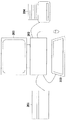
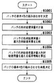
図5は、出力特性パッチ画像作成102の処理の詳細を示すブロック図であり、図6はその処理の手順、すなわち、ステップS402において行われる処理手順の詳細を示すフローチャートである。こらの図を参照して、パッチの作成処理を説明する。
【0031】
まず、ステップS1001において、パッチ使用色材組み合わせ決定901は、パッチを構成するY、M、C、Kの基本4色の組み合わせを決める。本実施形態では、Y、M、C、Kの各信号値0〜255を8等分して作られた8の4乗、つまり4096通りの組み合わせを定める。これらの計算された基本4色の組み合わせは、一時的にRAM305に記憶される。
【0032】
次に、ステップS1002において、パッチ色材総使用量計算902は、ステップS1001で決定された基本4色の組み合わせそれぞれについて、ステップS401で計算された各インクの色材使用量を参照しながらその組合せの色材総使用量を計算する。計算されたそれぞれの組合せごとの色材総使用量は、同様にRAM305に記憶される。
【0033】
さらに、ステップS1003で、パッチ色材総使用量比較903は、ステップS1002で算出された各組合せごとの色材総使用量と、ステップS401で計算された最大色材総使用量を比較し、その組合せの色材総使用量が最大色材総使用量を超えるか否かを判断をする。その組合せの色材総使用量が最大色材総使用量を超えるか否かの情報は、その組み合わせに対応付けられてRAM305に記憶される。
【0034】
次に、ステップS1004では、色材総使用量境界算出904は、最大色材総使用量を超えると判断された組合せを集め、それらの組み合わせそれぞれについて、最大色材総使用量を超える分の量をC、Mの色ごとに計算し、さらに、次のステップS1005おいて用いるパッチデータの圧縮率を境界情報として計算しそれをRAM305に記憶する。すなわち、この圧縮率は、最大色材総使用量を超える量の最大量を有するパッチ(後述の図7の点B)の信号値が、最大色材総使用量以内(本実施形態ではこれと等しい値)となるように定められるものであり、距離OBに対する距離ОB′の比に相当する。そして、次のステップS1005ではこの圧縮率で全てのパッチのデータについて均一に圧縮が行われるものである。
【0035】
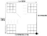
図7は、上記のように求められる最大色材総使用量の境界をパッチにおいて示す図である。同図は、上記基本4色の組合せによって作成され得るパッチを示し、YおよびKの信号を固定してCおよびMの信号値を変化させた場合のパッチが示されている。また、同図では、最小の正方形が1つのパッチを表わし、中間部分のパッチの図示は省略されている。
【0036】
計算される最大色材総使用量を超えない領域と超える領域との境界とは、同図において、1/4の円周で描かれた最大色材総使用量のラインである。なお、このラインは、説明および図示の便宜上円周で表しており、実際は境界のラインは、(Y、K、)C、Mの信号値の合計のインク(色材)使用量に換算した値が、一定の最大色材総使用量となるラインである。因みに、C、Mの信号値が同じ割合でインク使用量に換算される場合、このラインは直線となる。
【0037】
YおよびKの信号値が比較的大きい場合には、全体として色材総使用量も大きくなることから、図のようにパッチ画像上に最大色材総使用量のラインが現れる。すなわち、C、Mについての最大色材総使用量を表すラインよりもパッチを構成するCまたはM、あるいはその両方の信号値が大きい場合の、その組合せにより記録され得るパッチは、インクのオーバーフローが起きてしまうためにその記録が正確になされない。このため、本実施形態では、次のステップS1005で、全てのパッチについて均一な信号値の圧縮を行い、全てのパッチについて色材総使用量が上記ラインより内側の値となるようにする。
【0038】
すなわち、ステップS1005において、パッチ使用色材組み合わせ再決定905は、ステップS1004で計算された圧縮率に従い、全てのパッチのM、Cの値を圧縮する。なお、図1にて上述したように、M、Cのうち、色材使用量の計算において換算率(すなわち、総色材使用量に対する寄与率)が異なる色材がある場合には、その色材についてはその換算率に応じた圧縮率とする。例えば、換算率の最大が80%の場合は、上記計算された圧縮率の80%の圧縮率とする。以上の処理により、図7に示す、最も大きく最大色材総使用量を超える点Bは、原点に向かい矢印Aの方向に点B’の所まで圧縮され、図8に示されるパッチ画像のように、パッチ画像の全てのパッチにおける色材総使用量が最大色材総使用量を超えないように調整される。
【0039】
なお、上記の説明では、Y、Kの値を固定してこれらのある値のパッチについて説明したが、Y、Kの他の値のパッチについても同様に処理が行われ、ステップS401で計算の対象としたY、M、C、Kの全ての組合せのパッチについて圧縮を行うことはもちろんである。また、上例では、M、Cを圧縮の対象としたが、その対象を他の色材としてもよく、さらには、1次元的、3次元的、または4次元的に最大色材総使用量を計算し、それぞれ1、3または4つの色材を圧縮の対象としてもよい。
【0040】
以上の圧縮処理で基本4色の組み合わせが再決定されると、本ステップS402を終了する。この処理によって、記録されるパッチは全て最大色材総使用量の範囲内とすることができ、インク溢れなどのない適切なパッチを記録することができる。
【0041】
再び図4を参照すると、次のステップS403では、ステップS402で作成したパッチデータに基づき本実施形態のプリンタ204でプリント出力し、さらに測色する。パッチの測色は、分光光度計201などを用いて行うことができる。測色された各パッチのL*a*b*値の測色結果は、RAM305に一時的に記憶される。また、測色結果の容量が大きい場合は外部記憶装置308なども利用される。
【0042】
そして、ステップS404では、上記測色された範囲内で、Y(イエロー)、M(マゼンタ)、C(シアン)、R(レッド)、G(グリーン)とB(ブルー)6色相のそれぞれについて、それぞれの色の彩度が最大となるターゲットを設定する。
【0043】
各色相のターゲットとは、例えばシアンの色相を例にとると、白(White)→シアン(Cyan)→黒(Black)のターゲットが、L*C*平面上でどのように動くかを定めたものであり、これにより色再現にかかる色修正の特性が定められる。本実施形態では、このターゲットはL*a*b*空間の色として表され、その値はL*C*平面においてL*軸(明度軸)からの距離として表されるものである。そして、具体的なターゲットデータは、L*軸に沿った所定数の点について上記距離のデータとして表されるものである。
【0044】
一般的に、図9に示すように、白(White)→シアン(Cyan)→黒(Black)のL*C*平面におけるターゲットは、WhiteからBlackへと明度(L*)が低くなっていく際に、プライマリカラーであるCyanまでは彩度(C*)が高くなり、プライマリカラーからBlackに向かって彩度が低くなるように動く。このターゲットの設定においては、特にプライマリカラーから黒(Black)に向かって彩度が低くなっていく過程、例えば、CyanからBlackの領域においては一般にKをより多く入れ、そこにY、M、Cを加えるとより彩度が出せることが知られている。
【0045】
本実施形態では、まず、シアンからブラックの領域について、図10に示すL*C*平面で、曲線▲1▼で表される、Kをまったく入れない時のターゲットと、曲線▲2▼で表されるKを最大限に入れたときのターゲットをL*の所定範囲について求める。
【0046】
すなわち、本実施形態では、ステップS403で測色して得られたデータの範囲内で上記曲線▲1▼と曲線▲2▼が求められる。具体的には、ステップS402で求めた最大色材総使用量である境界の各パッチの測色値(本実施形態ではL*a*b*値)を参照して、その範囲内で彩度C*が最大となるようなそれぞれ曲線▲1▼と曲線▲2▼を求める。これにより、設定されたターゲットに基づいて次のステップS405で求められるY、M、C、Kの組合せにかかるテーブルデータは、最大色材総使用量の範囲内にあることになる。
【0047】
そして、この2つの曲線において、実際には、L*が高い所、つまり明るいところで早めにKを入れると彩度は高くなるが、Kの粒情感が目立つ、などのトレードオフを考慮し、シアンからブラックの領域においてKの入り始める点Aを定める。この定めた点Aで表されるL*から最暗点のブラックまでは、曲線▲3▼で表されるように、例えばスプライン関数などの所定の連続した関数式で滑らかに繋ぎ、それを白(White)→シアン(Cyan)→黒(Black)のターゲットとして設定する。以上のように計算された各色相のターゲットは、RAM305に記憶されるか、容量が大きい場合は外部記憶装置308なども利用される。
【0048】
次に、ステップS405において、ステップS404で設定されRAM305または外部記憶装置308に保存されている各色相のターゲットを実現するC、M、Y、Kの組み合わせを求め、これを色分解テーブルとする。
【0049】
具体的には、ターゲットを表す各L*a*b*値について、その近傍のパッチの測色値である、例えば8点あるいは4点を採り、それらパッチのY、M、C、K値について立方体補間あるいは四面体補間による補間演算を行い、C、M、Y、Kの組み合わせを求めるものである。もちろん、補間方法については上例に限られないことはもちろんである。
【0050】
図11は、以上のように求められたターゲットのうち、白(White)→シアン(Cyan)→黒(Black)のターゲットについて、それぞれC、M、Y、Kの色材量と色材総使用量を示す図である。横軸が白(White)→シアン(Cyan)→黒(Black)と変換する色を示し、縦軸は、各色材の色材量(インク量)については、それらの信号値で、色材総使用量はパーセントでそれぞれ示している。同図において、AはC(シアン)のインク量、BはM(マゼンタ)のインク量、CはY(イエロー)のインク量、DはK(ブラック)のインク量を信号値で表し、Eが色材総使用量である。
【0051】
この図から明きらかなように、算出されたC、M、Y、Kの組み合わせは最大色材総使用量の範囲内にあることがわかる。ステップS405を終えると、本処理を終了する。
【0052】
(第2の実施形態)
本実施形態は、上記第1の実施形態で求めた、色修正にかかる色分解テーブルを用いた実際の記録データ生成にかかる画像処理に関するものである。
【0053】
すなわち、第1実施形態で求めた、6色相のそれぞれの4色分解テーブルデータに基づき、所定の補間方法により、テーブルの格子点を規定するL*a*b*値、またはこれと対応付けられたR、G、B値などの全てに対応する色材信号C、M、Y、Kの組み合わせを求め、LUT(ルックアップテーブル)としてROM304等に記憶させる。
【0054】
なお、この記憶装置については、外部記憶装置308、CDドライブ310またはFDドライブ311、または外部機器であってもよく、外部機器の場合、モデムやネットワークカード等の伝送機器314を介しての際にRAM305に呼び出し使用する。
【0055】
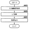
図12は、上記のように作成された色分解テーブルを用いた画像処理の手順を示すフローチャートである。
【0056】
図において、まず、ステップS601において、入力画像信号を取得する。入力画像信号は、図3に示す分光光度計201を用いて入力されたり、図3には図示しないが、カラーイメージスキャナ等を画像入力機器との接続I/O302に接続し、入力される他、外部記憶装置308、CDドライブ310やFDドライブ311からの入力も可能である。ここで、入力画像信号とは、R、G、B値やL*a*b*値などの色情報である。入力された入力画像信号は、一時的にRAM305に記憶される。
【0057】
次に、ステップS602において、入力された入力画像信号に対応する最適となる色材信号の組み合わせをRAM305に呼び出された上述のLUTを参照し決定する。
【0058】
そして、ステップS603では、入力画像信号の彩度を最大限に表した最適となる色材信号の組み合わせをRAM305を介して出力し、プリンタ204に対して記録信号として供給する。ステップS603を終えると、本処理を終了する。
【0059】
なお、上記の各実施形態では、色材としてインクの場合を例に採り説明したが、他の色材、例えば電子写真方式にかかるトナーを用いる場合についても同様に本発明を適用できることは以上の説明からも明らかである。
【0060】
(他の実施形態)
また、本発明は上記実施の形態を実現する為の装置及び方法のみに限定されるものではなく、上記システム又は装置内のコンピュータ(CPUあるいはMPU)に、上記実施の形態を実現する為のソフトウエアのプログラムコードを供給し、このプログラムコードに従って上記システムあるいは装置のコンピュータが上記各種デバイスを動作させることにより上記実施の形態を実現する場合も本発明の範疇に含まれる。
【0061】
またこの場合、図4、図6、図12に示した前記ソフトウエアのプログラムコード自体が上記実施の形態の機能を実現することになり、そのプログラムコード自体、及びそのプログラムコードをコンピュータに供給する為の手段、具体的には上記プログラムコードを格納した記憶媒体は本発明の範疇に含まれる。
【0062】
この様なプログラムコードを格納する記憶媒体としては、例えばフロッピー(登録商標)ディスク、ハードディスク、光ディスク、光磁気ディスク、CD−ROM、磁気テープ、不揮発性のメモリカード、ROM等を用いることができる。
【0063】
また、上記コンピュータが、供給されたプログラムコードのみに従って各種デバイスを制御することにより、上記実施の形態の機能が実現される場合だけではなく、上記プログラムコードがコンピュータ上で稼働しているOS(オペレーティングシステム)、あるいは他のアプリケーションソフト等と共同して上記実施の形態が実現される場合にもかかるプログラムコードは本発明の範疇に含まれる。
【0064】
更に、この供給されたプログラムコードが、コンピュータの機能拡張ボードやコンピュータに接続された機能拡張ユニットに備わるメモリに格納された後、そのプログラムコードの指示に基づいてその機能拡張ボードや機能格納ユニットに備わるCPU等が実際の処理の一部又は全部を行い、その処理によって上記実施の形態が実現される場合も本発明の範疇に含まれる。
また、上述した種々の特徴点の少なくとも1つを含む構成であれば本発明の範疇に含まれる。
【0065】
【発明の効果】
以上説明したように本発明によれば、パッチを出力するために用いられ得る複数種類の色材データの組合せであって、複数のパッチそれぞれについて定められた第1パッチデータが用意され、この第1パッチデータに対して各パッチの総色材使用量が、画像出力装置でパッチを出力する際に用いられる記録媒体に対するインク吸収性やトナー付着性などの色材付着特性を考慮して定められる最大色材総使用量以上のパッチがあるときは、全てのパッチについて最大色材総使用量以下となる処理を行い第2パッチデータを生成するので、このデータに基づいて出力されたパッチは、インク溢れやトナーが適切に付着しないなどのパッチ出力不良を生じることを防止できる。
【0066】
この結果、パッチのプリント出力不良による不適切な測色値が無く精度の高い測色値およびそれに基づくテーブルデータを得ることができる。
【図面の簡単な説明】
【図1】本発明の一実施形態にかかるカラープリンタの画像処理構成を示すブロック図である。
【図2】図1に示す上記画像処理を実行す具体的なる画像処理システムを示す図である。
【図3】図2に示したシステムおける特にパーソナルコンピュータの主要な要素を示すブロック図である。
【図4】図1に示した画像処理、具体的には図2および図3に示した構成において、実行される色分解テーブル作成処理の手順を示すフローチャートである。
【図5】図1に示した出力特性パッチ画像作成処理の詳細を示すブロック図である。
【図6】上記出力特性パッチ画像作成処理の手順の詳細を示すフローチャートである。
【図7】上記のパッチ画像作成処理で求められる最大色材総使用量の境界をパッチにおいて示す図である。
【図8】上記色分解テーブル作成処理における上記最大色材総使用量の境界情報に基づくパッチデータの圧縮処理の結果をパッチにおいて示す図である。
【図9】上記色分解テーブル作成処理で用いられる白→シアン→黒のL*C*平面におけるターゲットの一般的特性を説明する図である。
【図10】上記色分解テーブル作成処理で用いられる実施形態のターゲットを説明する図である。
【図11】上記実施形態で求められたターゲットについて、それぞれC、M、Y、Kの色材量と色材総使用量を示す図である。
【図12】上記実施形態で作成された色分解テーブルを用いた画像処理の手順を示すフローチャートである。
【符号の説明】
101 色材使用量計算
102 出力特性パッチ画像作成
103 ターゲット設定
104 基本4色色分解
201 分光光度計
202 パーソナルコンピュータ
204 プリンタ
303 CPU
304 ROM
305 RAM[0001]
TECHNICAL FIELD OF THE INVENTION
The present invention relates to an image processing method and an image processing apparatus, and more particularly, to a patch data generation process for obtaining a conversion relationship related to data generation of a color material such as ink used in an image output device such as an ink jet printer using a patch. It is about.
[0002]
[Prior art]
Generally, when a color image is printed out by an image output device such as a printer, four color materials of Y (yellow), M (magenta), C (cyan) and K (black) are used. For example, an ink jet printer uses Y, M, C, and K inks, and an electrophotographic copying machine or printer uses Y, M, C, and K toners.
[0003]
The color space realized by these color materials used in the image output device usually has a color space different from the original image data. Therefore, in the image processing for generating the color material data based on the image data, the original color space is used. Various image processing methods have been proposed to faithfully reproduce the colors and gradations indicated by the image data or to reproduce desired colors and the like.
[0004]
For example, Japanese Patent Application Laid-Open No. 2-136848 discloses an image processing method in which the problem of color reproducibility of 100% UCR (under color removal processing) performed as part of the above color material data generation processing is improved. Has been described. Here, among some combinations of Y, M, C, and K that can represent a certain color indicated by the original image data, the combination with the largest K is determined as the combination of Y, M, C, and K. According to this, in the 100% UCR, the value of the color of the minimum density replaced by K among Y, M, and C becomes 0, but Y, M, C, and C that do not include such a value of 0 It is stated that there can be combinations of K, and that image output can be performed without a decrease in saturation or density. Further, Japanese Patent Application Laid-Open No. 6-242523 discloses a K image which takes into account the reproduction range of Y, M, C, and K color materials, pseudo contours in an output image, interpolation accuracy, and the like for the image processing described in the above publication. Describes an image processing method for further improving the reproducibility.
[0005]
By the way, the above-described image processing for color correction is usually performed using a lookup table (LUT) having data for realizing the color correction and an interpolation operation. The contents of this table can be obtained by recording patches for a plurality of combinations of the color materials Y, M, C, and K and measuring the colors. Specifically, when the signal values of Y, M, C, and K constituting each patch are represented by 8 bits, for example, 256 values of each color are equally divided into 0, 32, 64,. The patch is recorded for 4096 colors which are combinations of the values of Y, M, C, and K that reproduce the color to be a predetermined target based on the colorimetric results. Data.
[0006]
[Problems to be solved by the invention]
However, even if image processing for improving reproducibility is performed in an image output device such as a printer as described above, actual printing (recording) in a printer or the like becomes inappropriate due to the relationship between color materials and recording paper. As a result, a desired image may not be reproduced.
[0007]
Since the processes described in the above two publications are basically processes for simultaneously using four color materials of Y, M, C, and K, the total amount of used color materials tends to increase. In particular, when trying to reproduce a color with high saturation at low lightness, the signal value of each color material increases, and the amount of each color material used increases. In this case, in an ink jet printer or the like, depending on the ink absorption characteristics of the recording paper, the ink cannot be absorbed sufficiently, causing overflow or bleeding of the ink, and the density or the like may not be accurately realized. Further, in an electrophotographic printer using toner, the toner may not be sufficiently fixed on the recording paper depending on the toner adhesion characteristics of the recording paper, and similarly, accurate density may not be realized. As a result, even if good image reproducibility is achieved in image processing for generating color material data, accurate image reproduction may not be possible as a result of actual recording.
[0008]
When the above-described patch data is generated and recorded based on the above image processing, a similar problem may occur. In particular, in patch recording, a patch of data that is prohibited in normal recording may be recorded, and the problem becomes more remarkable. For example, when the maximum amount of one color material is 100% and all the color materials are signal values using the maximum amount, the total color material amount applied to the recording paper is 400%. When the four color materials are used in the vicinity of the maximum amount as described above, the recording paper cannot absorb the four kinds of inks applied in a superimposed manner, and the electronic paper using the toner cannot be used. In a photographic printer, four color toners cannot be properly fixed on recording paper, and as a result, accurate patch reproduction cannot be performed.
[0009]
If a patch is not accurately recorded as described above, its colorimetric value naturally does not reflect the recording characteristics of the printer that has recorded it, and an accurate table cannot be created. As a result, the operation and processing for recording and measuring the color of the patch become useless for the incorrect patch.
[0010]
The problem of the amount of color material used is naturally determined by the relative characteristics between the recording paper and the color material, such as absorbency and adhesion. Therefore, even if the total color material usage is, for example, 300%, the same problem may occur depending on the recording paper used, and the total color material usage obtained based on the above-mentioned 100% UCR is the same. However, similar problems may occur due to the relative relationship with the recording paper.
[0011]
The present invention has been made in order to solve the above-described problem, and has as its object to record an accurate patch by preventing an excessive application of a coloring material such as ink or toner, thereby achieving high accuracy. It is an object of the present invention to provide an image processing method and an image processing apparatus that enable a colorimetric result to be obtained.
[0012]
[Means for Solving the Problems]
Therefore, in the present invention, an image processing method for generating data for outputting a patch used for adjusting output characteristics of an image output device that performs image output using a plurality of types of color materials from the image output device is provided. A combination of a plurality of types of color material data that can be used to output a patch, wherein the first patch data defined for each of the plurality of patches and the image output device of each of the plurality of color materials And a maximum total color material usage determined in consideration of the adhesion property to the recording medium used when outputting the patch in the first patch data, and a combination of a plurality of types of color material data for each patch in the first patch data is prepared. Based on the total amount of the color materials used to output the patch, the total amount of the color materials is calculated, and the total amount of the color materials is compared with the maximum total amount of the color materials for each patch. Performing a process on the first patch data such that the total color material usage of each patch is equal to or less than the maximum color material total usage based on the comparison for each patch, to generate second patch data. It is characterized by having done.
[0013]
An image processing apparatus for generating data for outputting a patch used for adjusting output characteristics of an image output apparatus that performs image output using a plurality of types of color materials from the image output apparatus, the patch including: Is a combination of a plurality of types of color material data that can be used to output the first patch data defined for each of the plurality of patches, and a patch is output by the image output device for each of the plurality of color materials. Means for holding the maximum color material total usage determined in consideration of the adhesion characteristics to the recording medium used at the time, and a combination of a plurality of types of color material data for each patch in the first patch data. Total use amount calculation means for calculating the total use amount of the plurality of types of color materials for outputting the patch, and the total use amount of the color materials and the maximum use amount And performing processing on the first patch data such that the total color material usage of each patch is equal to or less than the maximum color material total usage based on the comparison for each patch, and generating a second patch data. Data generating means.
[0014]
According to the above configuration, the first patch data, which is a combination of a plurality of types of color material data that can be used for outputting a patch and is defined for each of the plurality of patches, is prepared. On the other hand, the total amount of color material used for each patch is determined by taking into account the color material adhesion characteristics such as ink absorption and toner adhesion to the recording medium used when outputting the patch by the image output device. When there is a patch exceeding the used amount, the second patch data is generated by performing a process of not more than the maximum color material total used amount for all the patches. It is possible to prevent a patch output failure such as a case where the image does not adhere properly.
[0015]
BEST MODE FOR CARRYING OUT THE INVENTION
Hereinafter, embodiments of the present invention will be described in detail with reference to the drawings.
(1st Embodiment)
FIG. 1 is a block diagram showing an image processing configuration of a color printer according to an embodiment of the present invention. The process of forming a patch and generating table data based on the colorimetric results (hereinafter also referred to as “color separation process”) ). This configuration specifically shows processing executed by, for example, a printer driver of a host computer as described below, but these processings may be performed on an image output device side such as a printer, Alternatively, the host device and the image output device may share these processes, and it is apparent from the following description that the application of the present invention can be applied to any of these embodiments.
[0016]
As shown in FIG. 1, in the color separation processing, the color material usage amount and the maximum color material total usage amount of each of the four inks Y, M, C, and K used in the printer of the present embodiment are calculated by the color material
[0017]
The color material usage is determined for each of the Y, M, C, and K inks. In the present embodiment, the signal values 0 to 255 represented by the eight bits are calculated in a proportional relationship with 0% to 100%. Is what is done. Here, the usage amount “A”% basically means that when the 8-bit signal is subjected to quantization such as binarization to become ink ejection data in a printer and recording is performed on recording paper, the corresponding pixel is used. This means that an ink dot is formed with a probability of “A”% on average. However, in consideration of the permeability of each of the Y, M, C, and K inks, the signal values 0 to 255 may be calculated in a proportional relationship, for example, from 0% to 80% depending on the ink.
[0018]
Next, the maximum color material total use amount is calculated as described above. For example, when the color material use amount of the ink C is 100% (that is, the use amount at the maximum signal value of 255 is 100%), Information is obtained about the type of recording medium used in the printer, that is, whether the recording medium used is plain paper, coated paper, OHP paper, or the like, and based on this information, the recording medium can absorb the ink C by up to what percentage. Is calculated.
[0019]
The output characteristic
[0020]
The target setting 103 is based on the colorimetric data of the above-mentioned patch, and is based on the six hues of Y (yellow), M (magenta), C (cyan), R (red), G (green), and B (blue). Create a target with the highest degree. Then, the basic four-
[0021]
FIG. 2 is a diagram illustrating a specific image processing system that executes the image processing.
[0022]
In the figure, 201 indicates a spectrophotometer as an image signal input device, and 202 indicates a personal computer as a computer system. The
[0023]
FIG. 3 is a block diagram showing main elements of the
[0024]
In the figure,
[0025]
[0026]
[0027]
FIG. 4 is a flowchart showing a procedure of a color separation table creation process executed in the image processing shown in FIG. 1, specifically, in the configuration shown in FIGS. Note that a computer-executable program describing the procedure shown in the flowchart of FIG. 4 is stored in the
[0028]
First, in step S401, the color material usage is calculated for the maximum color material total usage and the signal values obtained by equally dividing the signal values of Y, M, C, and K into eight. Note that the setting of the patch data is not limited to this, and may be any setting, for example, a combination of color materials in which signal values are randomly determined. As described above with reference to FIG. 1, the color material usage is calculated for each of Y, M, C, and K, and the color material usage (%) corresponding to each of the 256 signal values 0 to 255. For the maximum total color material usage, information on the type of recording medium to be used in the printer of the present embodiment is obtained, and the amount of ink (%) that can be absorbed by the recording medium indicated by this information is calculated. Specifically, it can be determined from the relationship between the type of the recording medium determined in advance and the maximum amount of ink that can be absorbed by the type. The color material usage amount and the maximum color material total usage amount of each ink calculated as described above are temporarily stored in the
[0029]
Next, in step S402, a patch is created within a range where ink overflow does not occur by the output characteristic patch image creation 102 (FIG. 1).
[0030]
FIG. 5 is a block diagram showing the details of the processing of the output characteristic
[0031]
First, in step S1001, a patch use color
[0032]
Next, in step S1002, the patch color material
[0033]
Further, in step S1003, the patch color material
[0034]
Next, in step S1004, the color material total usage
[0035]
FIG. 7 is a diagram showing a boundary of the maximum color material total usage amount obtained as described above in a patch. This figure shows a patch that can be created by the combination of the four basic colors, and shows a patch in which the Y and K signals are fixed and the C and M signal values are changed. Also, in the figure, the smallest square represents one patch, and the illustration of the patch in the middle part is omitted.
[0036]
The boundary between the region that does not exceed the calculated maximum color material total usage and the region that exceeds the calculated maximum color material total usage is a line of the maximum color material total usage drawn with a quarter of the circumference in FIG. Note that this line is represented by a circle for convenience of explanation and illustration, and the boundary line is actually a value converted into the total ink (color material) usage of the signal values of (Y, K,) C and M. Is a line with a certain maximum color material total usage. By the way, when the signal values of C and M are converted into the ink consumption at the same ratio, this line becomes a straight line.
[0037]
When the signal values of Y and K are relatively large, the total amount of color material used becomes large as a whole, so that a line of the maximum total used color material appears on the patch image as shown in the figure. In other words, when the signal value of C or M or both of the signals constituting the patch is larger than the line indicating the maximum total amount of color material used for C and M, the patch that can be recorded by the combination thereof has an ink overflow. The record is not made correctly because it happens. For this reason, in the present embodiment, in the next step S1005, uniform signal value compression is performed for all patches, and the total amount of color material used for all patches is set to a value inside the above line.
[0038]
That is, in step S1005, the patch use color material combination re-determination 905 compresses the values of M and C of all patches according to the compression ratio calculated in step S1004. As described above with reference to FIG. 1, if there is a color material having a different conversion ratio (that is, a contribution ratio to the total color material usage) in the calculation of the color material usage among M and C, the color For materials, the compression ratio is set according to the conversion ratio. For example, if the maximum conversion rate is 80%, the compression rate is set to 80% of the calculated compression rate. By the above processing, the point B, which is the largest and exceeds the maximum total amount of color material used as shown in FIG. 7, is compressed to the point B 'in the direction of the arrow A toward the origin, as shown in the patch image shown in FIG. In addition, adjustment is performed so that the total color material usage in all patches of the patch image does not exceed the maximum color material total usage.
[0039]
In the above description, the Y and K values are fixed and the patches having certain values are described. However, the processing is similarly performed for the patches having other values of Y and K, and the calculation is performed in step S401. Needless to say, compression is performed on patches of all combinations of Y, M, C, and K as targets. Further, in the above example, M and C are targets of compression, but the targets may be other color materials, and further, the maximum total color material usage in one-dimensional, three-dimensional, or four-dimensional manner. May be calculated, and one, three, or four color materials may be subjected to compression.
[0040]
When the combination of the four basic colors is determined again by the above-described compression processing, step S402 ends. By this processing, all the patches to be recorded can be within the range of the maximum color material total usage, and an appropriate patch without ink overflow or the like can be recorded.
[0041]
Referring to FIG. 4 again, in the next step S403, the
[0042]
Then, in step S404, within the colorimetric range, each of the six hues of Y (yellow), M (magenta), C (cyan), R (red), G (green) and B (blue) is Set the target that maximizes the saturation of each color.
[0043]
The target of each hue defines how a target of white (White) → cyan (Cyan) → black (Black) moves on the L * C * plane, for example, taking a cyan hue as an example. This defines the characteristics of color correction for color reproduction. In the present embodiment, the target is represented as the color of L * a * b * space, the value is represented as the distance from the L * axis (brightness axis) in L * C * plane. The specific target data is expressed as the data of the distance for a predetermined number of points along the L * axis.
[0044]
In general, as shown in FIG. 9, a target in the L * C * plane of white (White) → cyan (Cyan) → black (Black) decreases in brightness (L * ) from White to Black. At this time, the saturation (C * ) increases up to the primary color Cyan, and the saturation decreases from the primary color toward Black. In setting the target, in particular, in the process of decreasing the saturation from the primary color to black (Black), for example, in a region from Cyan to Black, generally, more K is added, and Y, M, C are added there. It is known that saturation can be obtained by adding.
[0045]
In the present embodiment, first, in the L * C * plane shown in FIG. 10, a target when no K is inserted and a target when no K is inserted are represented by a curve {circle around (2)} in the L * C * plane shown in FIG. The target when the maximum value of K is set is determined for a predetermined range of L * .
[0046]
That is, in the present embodiment, the curves (1) and (2) are obtained within the range of the data obtained by performing the color measurement in step S403. Specifically, referring to the colorimetric value (in this embodiment, L * a * b * value) of each patch at the boundary, which is the maximum total color material use amount obtained in step S402, the saturation is set within the range. A curve (1) and a curve (2 ) that maximize C * are determined. As a result, the table data for the combination of Y, M, C, and K determined in the next step S405 based on the set target is within the range of the maximum color material total usage.
[0047]
In addition, in these two curves, in actuality, if K is added earlier in a place where L * is high, that is, in a bright place, the saturation becomes higher, but in consideration of a trade-off such that the graininess of K is conspicuous, cyan is taken into consideration. , A point A where K starts to enter in a black region is determined. From L * represented by the determined point A to black, the darkest point, as shown by the curve (3), the connection is smoothly connected by a predetermined continuous function formula such as a spline function, and is connected to white. (White) → Cyan → Cyan (Black) are set as targets. The target of each hue calculated as described above is stored in the
[0048]
Next, in step S405, a combination of C, M, Y, and K that realizes the target of each hue set in step S404 and stored in the
[0049]
Specifically, for each L * a * b * value representing the target, the colorimetric values of the patches in the vicinity, for example, 8 points or 4 points are taken, and the Y, M, C, K values of those patches are Interpolation by cubic interpolation or tetrahedral interpolation is performed to obtain a combination of C, M, Y, and K. Of course, the interpolation method is not limited to the above example.
[0050]
FIG. 11 shows the color material amounts and the total use of color materials of C, M, Y, and K for the targets of white (White) → cyan (Cyan) → black (Black) among the targets obtained as described above. It is a figure which shows a quantity. The horizontal axis indicates the color to be converted from white (White) to cyan (Cyan) to black (Black), and the vertical axis indicates the signal value of the color material amount (ink amount) of each color material and the color material total. The amounts used are given in percentages. In the figure, A represents the amount of C (cyan) ink, B represents the amount of M (magenta) ink, C represents the amount of Y (yellow) ink, D represents the amount of K (black) ink by signal values, and Is the total amount of coloring material used.
[0051]
As is apparent from this figure, the calculated combination of C, M, Y, and K is within the range of the maximum total color material usage. When step S405 ends, the present process ends.
[0052]
(Second embodiment)
The present embodiment relates to image processing for actual print data generation using a color separation table for color correction obtained in the first embodiment.
[0053]
That is, based on the four-color separation table data of each of the six hues obtained in the first embodiment, the L * a * b * values that define the grid points of the table or the L * a * b * values that are associated therewith are determined by a predetermined interpolation method. A combination of the color material signals C, M, Y, and K corresponding to all of the R, G, B values, etc., is obtained and stored in the
[0054]
Note that this storage device may be the
[0055]
FIG. 12 is a flowchart illustrating a procedure of image processing using the color separation table created as described above.
[0056]
In the figure, first, in step S601, an input image signal is obtained. The input image signal is input by using the
[0057]
Next, in step S602, an optimum combination of color material signals corresponding to the input image signal is determined by referring to the above-described LUT called by the
[0058]
Then, in step S603, an optimal combination of color material signals that maximizes the saturation of the input image signal is output via the
[0059]
In each of the above embodiments, the case where ink is used as a color material has been described as an example. However, the present invention can be similarly applied to a case where another color material, for example, a toner according to an electrophotographic method is used. It is clear from the explanation.
[0060]
(Other embodiments)
In addition, the present invention is not limited to only the apparatus and method for realizing the above-described embodiment, and the computer (CPU or MPU) in the system or the apparatus is provided with software for realizing the above-described embodiment. The present invention also includes a case in which the above-described embodiment is implemented by supplying a program code of software and causing the computer of the system or apparatus to operate the various devices according to the program code.
[0061]
In this case, the program code of the software shown in FIGS. 4, 6, and 12 implements the functions of the above-described embodiment, and the program code itself and the program code are supplied to the computer. Means for this, specifically, a storage medium storing the above program code are included in the scope of the present invention.
[0062]
As a storage medium for storing such a program code, for example, a floppy (registered trademark) disk, hard disk, optical disk, magneto-optical disk, CD-ROM, magnetic tape, nonvolatile memory card, ROM, or the like can be used.
[0063]
In addition to the case where the computer controls various devices in accordance with only the supplied program code to realize the functions of the above-described embodiment, not only the case where the program code is run on an OS (Operating System) running on the computer Such a program code is also included in the scope of the present invention when the above-described embodiment is implemented in cooperation with a system) or other application software.
[0064]
Further, after the supplied program code is stored in the memory provided in the function expansion board of the computer or the function expansion unit connected to the computer, the program code is stored in the function expansion board or the function storage unit based on the instruction of the program code. The present invention also includes a case where a provided CPU or the like performs part or all of the actual processing, and the above-described embodiment is realized by the processing.
A configuration including at least one of the various features described above is included in the scope of the present invention.
[0065]
【The invention's effect】
As described above, according to the present invention, the first patch data, which is a combination of a plurality of types of color material data that can be used for outputting a patch and is defined for each of the plurality of patches, is prepared. The total amount of color material used for each patch with respect to one patch data is determined in consideration of color material adhesion characteristics such as ink absorbency and toner adhesion to a recording medium used when outputting a patch by the image output device. When there is a patch that is equal to or more than the maximum color material total usage amount, the processing that reduces the total color material total usage amount to all patches is performed to generate the second patch data. Therefore, the patches output based on this data are: It is possible to prevent the occurrence of patch output defects such as overflow of ink and improper adhesion of toner.
[0066]
As a result, it is possible to obtain colorimetric values with high accuracy and table data based on the colorimetric values without inappropriate colorimetric values due to poor print output of the patch.
[Brief description of the drawings]
FIG. 1 is a block diagram illustrating an image processing configuration of a color printer according to an embodiment of the present invention.
FIG. 2 is a diagram showing a specific image processing system that executes the image processing shown in FIG. 1;
FIG. 3 is a block diagram showing main elements of a personal computer in the system shown in FIG. 2;
FIG. 4 is a flowchart illustrating a procedure of a color separation table creation process executed in the image processing illustrated in FIG. 1, specifically, in the configuration illustrated in FIGS.
FIG. 5 is a block diagram illustrating details of an output characteristic patch image creation process illustrated in FIG. 1;
FIG. 6 is a flowchart illustrating details of a procedure of the output characteristic patch image creation processing.
FIG. 7 is a diagram showing, in a patch, a boundary of a maximum total color material use amount obtained in the above-described patch image creation processing.
FIG. 8 is a diagram illustrating, in a patch, a result of patch data compression processing based on boundary information of the maximum total color material usage in the color separation table creation processing.
FIG. 9 is a diagram for explaining general characteristics of a target in an L * C * plane of white → cyan → black used in the color separation table creation processing.
FIG. 10 is a diagram illustrating a target of the embodiment used in the color separation table creation processing.
FIG. 11 is a diagram showing the amounts of color materials C, M, Y, and K and the total amount of color materials used for the targets obtained in the embodiment.
FIG. 12 is a flowchart illustrating a procedure of image processing using the color separation table created in the embodiment.
[Explanation of symbols]
101 Calculation of
304 ROM
305 RAM
Claims (20)
パッチを出力するために用いられ得る複数種類の色材データの組合せであって、複数のパッチそれぞれについて定められた第1パッチデータと、複数種類の色材それぞれの、前記画像出力装置でパッチを出力する際に用いられる記録媒体に対する付着特性を考慮して定められる最大色材総使用量とを用意し、
前記第1パッチデータにおけるパッチごとの、複数種類の色材データの組合せに基づき、当該パッチを出力するための当該複数種類の色材の総使用量を求め、
パッチごとにその総色材使用量と前記最大色材総使用量とを比較し、該パッチごとの比較に基づき、前記第1パッチデータに対して各パッチの総色材使用量が前記最大色材総使用量以下となる処理を行い、第2パッチデータを生成する、
ステップを有したことを特徴とする画像処理方法。An image processing method for generating data for outputting a patch used for adjusting an output characteristic of an image output device that performs image output using a plurality of types of color materials from the image output device,
A combination of a plurality of types of color material data that can be used to output a patch, the first patch data defined for each of the plurality of patches, and the patch of each of the plurality of types of color materials in the image output device. Prepare the maximum color material total usage determined in consideration of the adhesion characteristics to the recording medium used when outputting,
Based on a combination of a plurality of types of color material data for each patch in the first patch data, a total usage amount of the plurality of types of color materials for outputting the patch is determined,
The total color material usage for each patch is compared with the maximum color material total usage, and based on the comparison for each patch, the total color material usage for each patch is compared with the maximum color material usage for the first patch data. Perform processing that is less than the total amount of material used to generate second patch data,
An image processing method comprising steps.
パッチを出力するために用いられ得る複数種類の色材データの組合せであって、複数のパッチそれぞれについて定められた第1パッチデータと、複数種類の色材それぞれの、前記画像出力装置でパッチを出力する際に用いられる記録媒体に対する付着特性を考慮して定められる最大色材総使用量とを保持する手段と、
前記第1パッチデータにおけるパッチごとの、複数種類の色材データの組合せに基づき、当該パッチを出力するための当該複数種類の色材の総使用量を求める総使用量計算手段と、
パッチごとにその総色材使用量と前記最大色材総使用量とを比較し、該パッチごとの比較に基づき、前記第1パッチデータに対して各パッチの総色材使用量が前記最大色材総使用量以下となる処理を行い、第2パッチデータを生成するパッチデータ生成手段と、
を具えたことを特徴とする画像処理装置。An image processing apparatus that generates data for outputting a patch used for adjusting output characteristics of an image output apparatus that performs image output using a plurality of types of color materials from the image output apparatus,
A combination of a plurality of types of color material data that can be used to output a patch, the first patch data defined for each of the plurality of patches, and the patch of each of the plurality of types of color materials in the image output device. Means for holding a maximum color material total usage determined in consideration of the adhesion characteristics to the recording medium used when outputting,
A total use amount calculation unit for calculating a total use amount of the plurality of types of color materials for outputting the patch based on a combination of a plurality of types of color material data for each patch in the first patch data;
The total color material usage for each patch is compared with the maximum color material total usage, and based on the comparison for each patch, the total color material usage for each patch is compared with the maximum color material usage for the first patch data. Patch data generating means for performing processing that is equal to or less than the total material usage and generating second patch data;
An image processing apparatus comprising:
パッチを出力するために用いられ得る複数種類の色材データの組合せであって、複数のパッチそれぞれについて定められた第1パッチデータと、複数種類の色材それぞれの、前記画像出力装置でパッチを出力する際に用いられる記録媒体に対する付着特性を考慮して定められる最大色材総使用量とを用意し、
前記第1パッチデータにおけるパッチごとの、複数種類の色材データの組合せに基づき、当該パッチを出力するための当該複数種類の色材の総使用量を求め、
パッチごとにその総色材使用量と前記最大色材総使用量とを比較し、該パッチごとの比較に基づき、前記第1パッチデータに対して各パッチの総色材使用量が前記最大色材総使用量以下となる処理を行い、第2パッチデータを生成する、
ステップを有した処理であることを特徴とするプログラム。When read by the computer, the computer generates data for outputting a patch used for adjusting output characteristics of the image output device that performs image output using a plurality of types of color materials from the image output device. A program for executing image processing, wherein the image processing includes:
A combination of a plurality of types of color material data that can be used to output a patch, the first patch data defined for each of the plurality of patches, and the patch of each of the plurality of types of color materials in the image output device. Prepare the maximum color material total usage determined in consideration of the adhesion characteristics to the recording medium used when outputting,
Based on a combination of a plurality of types of color material data for each patch in the first patch data, a total usage amount of the plurality of types of color materials for outputting the patch is determined,
The total color material usage for each patch is compared with the maximum color material total usage, and based on the comparison for each patch, the total color material usage for each patch is compared with the maximum color material usage for the first patch data. Perform processing that is less than the total amount of material used to generate second patch data,
A program characterized by processing having steps.
パッチを出力するために用いられ得る複数種類の色材データの組合せであって、複数のパッチそれぞれについて定められた第1パッチデータと、複数種類の色材それぞれの、前記画像出力装置でパッチを出力する際に用いられる記録媒体に対する付着特性を考慮して定められる最大色材総使用量とを用意し、
前記第1パッチデータにおけるパッチごとの、複数種類の色材データの組合せに基づき、当該パッチを出力するための当該複数種類の色材の総使用量を求め、
パッチごとにその総色材使用量と前記最大色材総使用量とを比較し、該パッチごとの比較に基づき、前記第1パッチデータに対して各パッチの総色材使用量が前記最大色材総使用量以下となる処理を行い、第2パッチデータを生成する、
ステップを有した処理であることを特徴とする記憶媒体。Executes image processing for generating data for outputting a patch used for adjusting output characteristics of an image output device that outputs images using a plurality of types of color materials from the image output device so that the image can be read by a computer. A storage medium storing a program to be executed, wherein the image processing includes:
A combination of a plurality of types of color material data that can be used to output a patch, the first patch data defined for each of the plurality of patches, and the patch of each of the plurality of types of color materials in the image output device. Prepare the maximum color material total usage determined in consideration of the adhesion characteristics to the recording medium used when outputting,
Based on a combination of a plurality of types of color material data for each patch in the first patch data, a total usage amount of the plurality of types of color materials for outputting the patch is determined,
The total color material usage for each patch is compared with the maximum color material total usage, and based on the comparison for each patch, the total color material usage for each patch is compared with the maximum color material usage for the first patch data. Perform processing that is less than the total amount of material used to generate second patch data,
A storage medium characterized by processing having steps.
Priority Applications (3)
| Application Number | Priority Date | Filing Date | Title |
|---|---|---|---|
| JP2002224166A JP2004058626A (en) | 2002-07-31 | 2002-07-31 | Image processing method and image processing apparatus |
| US10/628,406 US6923523B2 (en) | 2002-07-31 | 2003-07-29 | Image processing method and image processing apparatus |
| EP03254758A EP1392050A3 (en) | 2002-07-31 | 2003-07-30 | Image processing method and image processing apparatus |
Applications Claiming Priority (1)
| Application Number | Priority Date | Filing Date | Title |
|---|---|---|---|
| JP2002224166A JP2004058626A (en) | 2002-07-31 | 2002-07-31 | Image processing method and image processing apparatus |
Publications (2)
| Publication Number | Publication Date |
|---|---|
| JP2004058626A true JP2004058626A (en) | 2004-02-26 |
| JP2004058626A5 JP2004058626A5 (en) | 2005-10-27 |
Family
ID=31943734
Family Applications (1)
| Application Number | Title | Priority Date | Filing Date |
|---|---|---|---|
| JP2002224166A Pending JP2004058626A (en) | 2002-07-31 | 2002-07-31 | Image processing method and image processing apparatus |
Country Status (1)
| Country | Link |
|---|---|
| JP (1) | JP2004058626A (en) |
Cited By (4)
| Publication number | Priority date | Publication date | Assignee | Title |
|---|---|---|---|---|
| JP2007068001A (en) * | 2005-09-01 | 2007-03-15 | Ricoh Co Ltd | Image processing method, program, image processing apparatus, and image forming system |
| US7847974B2 (en) | 2004-07-16 | 2010-12-07 | Sharp Laboratories Of America, Inc. | Systems and methods for dynamically limiting total colorant coverage in a color rendering system |
| US7889402B2 (en) | 2007-03-28 | 2011-02-15 | Sharp Laboratories Of America, Inc. | Method for limiting total colorant coverage using multidimensional simplicial subdivision and barycentric interpolation |
| JP2013154594A (en) * | 2012-01-31 | 2013-08-15 | Canon Inc | Inkjet recording apparatus and calibration method |
-
2002
- 2002-07-31 JP JP2002224166A patent/JP2004058626A/en active Pending
Cited By (4)
| Publication number | Priority date | Publication date | Assignee | Title |
|---|---|---|---|---|
| US7847974B2 (en) | 2004-07-16 | 2010-12-07 | Sharp Laboratories Of America, Inc. | Systems and methods for dynamically limiting total colorant coverage in a color rendering system |
| JP2007068001A (en) * | 2005-09-01 | 2007-03-15 | Ricoh Co Ltd | Image processing method, program, image processing apparatus, and image forming system |
| US7889402B2 (en) | 2007-03-28 | 2011-02-15 | Sharp Laboratories Of America, Inc. | Method for limiting total colorant coverage using multidimensional simplicial subdivision and barycentric interpolation |
| JP2013154594A (en) * | 2012-01-31 | 2013-08-15 | Canon Inc | Inkjet recording apparatus and calibration method |
Similar Documents
| Publication | Publication Date | Title |
|---|---|---|
| US7864371B2 (en) | Image processing apparatus, image processing method, and computer product | |
| JP4623630B2 (en) | Image processing apparatus, image processing method, program, image forming apparatus, and image forming system | |
| US6923523B2 (en) | Image processing method and image processing apparatus | |
| JP4206743B2 (en) | Color image processing method, color image processing apparatus, color image processing program, and storage medium | |
| JP4022748B2 (en) | Color processing method, color processing apparatus, recording medium, color processing program, and image forming apparatus | |
| JP4475623B2 (en) | Color processing method and color processing apparatus | |
| JP4974853B2 (en) | Image processing apparatus, image processing method, and program | |
| US20040183814A1 (en) | Method of generating color separation table | |
| US7032989B2 (en) | Image processing method and image processing apparatus | |
| JP4252748B2 (en) | Conversion table generation method, program, color copier | |
| JP3912486B2 (en) | Color processing method, storage medium, color processing apparatus, color conversion apparatus, and image forming apparatus | |
| US8773723B2 (en) | Generating color separation table for printer having color forming materials with high and low relative densities using a gamut boundary to limit use of dark color material | |
| JP3963444B2 (en) | Image processing method and image processing apparatus | |
| JP6155644B2 (en) | Image processing apparatus, image processing method, program, and storage medium | |
| JP3833196B2 (en) | Image processing apparatus, image processing method, and computer program | |
| JP2005295153A (en) | Color conversion apparatus and method | |
| JP2004058626A (en) | Image processing method and image processing apparatus | |
| JP2004058623A (en) | Image processing method and image processing apparatus | |
| JP4228207B2 (en) | Color image processing method, color image processing apparatus, color image processing program, and storage medium | |
| JP3854644B2 (en) | Image processing method and apparatus | |
| JP2007060151A (en) | Color processing method and apparatus | |
| JP2004058625A (en) | Image processing method and image processing apparatus | |
| JP5014192B2 (en) | Color processing apparatus and color processing method | |
| JP4408774B2 (en) | Color processing apparatus and color processing method | |
| JP4921339B2 (en) | Color processing apparatus and method |
Legal Events
| Date | Code | Title | Description |
|---|---|---|---|
| A521 | Written amendment |
Free format text: JAPANESE INTERMEDIATE CODE: A523 Effective date: 20050729 |
|
| A621 | Written request for application examination |
Free format text: JAPANESE INTERMEDIATE CODE: A621 Effective date: 20050729 |
|
| A131 | Notification of reasons for refusal |
Free format text: JAPANESE INTERMEDIATE CODE: A131 Effective date: 20080523 |
|
| A521 | Written amendment |
Free format text: JAPANESE INTERMEDIATE CODE: A523 Effective date: 20080722 |
|
| A02 | Decision of refusal |
Free format text: JAPANESE INTERMEDIATE CODE: A02 Effective date: 20081125 |
|
| RD13 | Notification of appointment of power of sub attorney |
Free format text: JAPANESE INTERMEDIATE CODE: A7433 Effective date: 20090106 |
|
| A521 | Written amendment |
Free format text: JAPANESE INTERMEDIATE CODE: A821 Effective date: 20090106 |