JP2004100151A - Buried joint for highway bridge and embedment type joint for highway bridge - Google Patents
Buried joint for highway bridge and embedment type joint for highway bridge Download PDFInfo
- Publication number
- JP2004100151A JP2004100151A JP2002259134A JP2002259134A JP2004100151A JP 2004100151 A JP2004100151 A JP 2004100151A JP 2002259134 A JP2002259134 A JP 2002259134A JP 2002259134 A JP2002259134 A JP 2002259134A JP 2004100151 A JP2004100151 A JP 2004100151A
- Authority
- JP
- Japan
- Prior art keywords
- joint
- road bridge
- buried
- rubber layer
- load
- Prior art date
- Legal status (The legal status is an assumption and is not a legal conclusion. Google has not performed a legal analysis and makes no representation as to the accuracy of the status listed.)
- Granted
Links
- 230000007423 decrease Effects 0.000 claims description 6
- 230000006835 compression Effects 0.000 abstract description 6
- 238000007906 compression Methods 0.000 abstract description 6
- 239000010410 layer Substances 0.000 description 71
- 239000000463 material Substances 0.000 description 30
- 230000008602 contraction Effects 0.000 description 18
- 239000010426 asphalt Substances 0.000 description 11
- 238000010276 construction Methods 0.000 description 10
- 150000001875 compounds Chemical class 0.000 description 8
- 229910000831 Steel Inorganic materials 0.000 description 6
- 239000010959 steel Substances 0.000 description 6
- 239000004567 concrete Substances 0.000 description 5
- 238000006073 displacement reaction Methods 0.000 description 4
- 239000000945 filler Substances 0.000 description 4
- 238000010438 heat treatment Methods 0.000 description 4
- 229920005989 resin Polymers 0.000 description 4
- 239000011347 resin Substances 0.000 description 4
- 238000005336 cracking Methods 0.000 description 3
- 230000000694 effects Effects 0.000 description 3
- 229920001875 Ebonite Polymers 0.000 description 2
- PPBRXRYQALVLMV-UHFFFAOYSA-N Styrene Chemical compound C=CC1=CC=CC=C1 PPBRXRYQALVLMV-UHFFFAOYSA-N 0.000 description 2
- 238000010030 laminating Methods 0.000 description 2
- 239000007788 liquid Substances 0.000 description 2
- 239000002184 metal Substances 0.000 description 2
- 238000000034 method Methods 0.000 description 2
- 239000000203 mixture Substances 0.000 description 2
- 239000004033 plastic Substances 0.000 description 2
- 239000004575 stone Substances 0.000 description 2
- 239000002023 wood Substances 0.000 description 2
- 206010039203 Road traffic accident Diseases 0.000 description 1
- 238000010521 absorption reaction Methods 0.000 description 1
- 238000005452 bending Methods 0.000 description 1
- 230000033228 biological regulation Effects 0.000 description 1
- 238000005266 casting Methods 0.000 description 1
- 239000004568 cement Substances 0.000 description 1
- 239000011083 cement mortar Substances 0.000 description 1
- 238000005520 cutting process Methods 0.000 description 1
- 230000005489 elastic deformation Effects 0.000 description 1
- 239000006260 foam Substances 0.000 description 1
- 230000001771 impaired effect Effects 0.000 description 1
- 238000004519 manufacturing process Methods 0.000 description 1
- 238000002844 melting Methods 0.000 description 1
- 230000008018 melting Effects 0.000 description 1
- 238000002156 mixing Methods 0.000 description 1
- 239000004570 mortar (masonry) Substances 0.000 description 1
- 238000002360 preparation method Methods 0.000 description 1
- 238000003825 pressing Methods 0.000 description 1
- 238000007665 sagging Methods 0.000 description 1
- 239000007787 solid Substances 0.000 description 1
- 239000002344 surface layer Substances 0.000 description 1
- 238000004078 waterproofing Methods 0.000 description 1
Images



Landscapes
- Road Paving Structures (AREA)
- Bridges Or Land Bridges (AREA)
Abstract
Description
【0001】
【発明の属する技術分野】
本発明は、道路橋の埋設型ジョイント用の埋設継手及び道路橋の埋設型ジョイントに関する。
【0002】
【従来の技術】
埋設型ジョイントは、主として伸縮量の比較的小さな道路橋に適用され、連続舗装された舗装材の変形によって道路橋本体の伸縮を吸収するものとして知られている。その基本的な構造は図1に示されている。すなわち、道路橋遊間aの両側において、道路橋本体bの端部に段部cが形成され、遊間aに目地材dが詰められ、目地材dを覆うように段部c,cの上に弾性コンパウンドeが打設され、その上から防水シートfが敷かれて、その上に舗装gが施されている。
【0003】
また、埋設型ジョイントに関して、上記弾性コンパウンドを用いずに、工場製作されたプレハブ舗装部材(上層には舗装材層が設けられ、下層には間隙を存して左右に分離した一対の支承板が設けられており、一対の支承板の各々を遊間両側の道路橋本体に固定するようになっているもの)を連続舗装の下に埋設するものがある(例えば特許文献1参照)。
【0004】
また、埋設型ジョイントの舗装下にゴム板と鋼板とを接着してなる埋設継手(上層には一枚物の鋼板が設けられ、下層には左右に分離した一対のゴム板が設けられているものであり、一対のゴム板の各々を遊間両側の道路橋本体に固定するようになっているもの)を埋設するものがある(例えば特許文献2参照)。
【0005】
【特許文献1】
特公昭60−39801号公報
【特許文献2】
特公昭60−9605号公報
【0006】
【発明が解決しようとする課題】
上記埋設型ジョイントによれば、道路橋継目部で舗装が途切れることなく連続しているから、自動車の走行性がよく、振動・騒音が少なくなるが、弾性コンパウンドeの流動により舗装が波打ち状態になったり、遊間を存して相対する道路橋本体の相対的な上下変位や道路橋本体の伸縮に起因して遊間上の舗装にクラックを生じ易いという問題がある。このクラックは、継目長手方向(橋軸と交差する方向)に延びたものになるから、自動車の走行性が悪くなる。さらに、舗装が自動車通過時の衝撃でクラック部分から欠けていき、クラック部分が徐々に大きな溝になって走行性が益々悪くなっていくとともに、騒音・振動が大きくなり、走行安全性も損なわれてくる。
【0007】
また、上記弾性コンパウンドeは、ゴム、アスファルト及び砕石の混合物によって形成されているので、道路橋本体の伸縮吸収性や応力分散性が悪い。また、施工に際しては、現場においてまず固形ゴム及びアスファルト(又はシート状のゴム入りアスファルト)の必要量を溶解槽にて加熱溶解し、この溶解物をさらに砕石と共にミキサーに投入して再度加熱混合する必要があり、現場における準備が大掛かりになり且つ面倒であるとともに、手間と時間がかかる。また、上記段部cに打設した後も、弾性コンパウンドeが冷めて固化するまでは防水シートfの施工及び舗装gをすることができない。このため、工事時間が長くなって、1回の夜間工事又は昼間工事のみで施工を完了することができず、早朝又は夕方に工事を中断し、アスファルト合材を舗装厚さ分仮詰めしたり、覆工板を道路橋継目部に被せて仮復旧し(道路交通を可能にし)、改めて次の夜又は昼に続きの工事をしなければならなくなる。従って、工事のために交通規制をする期間が倍加して費用が嵩むとともに、交通の安全に支障を来す。
【0008】
これに対して、特公昭60−39801号公報に記載されているプレハブ舗装部材を用いれば、上記弾性コンパウンドの有する問題は解消されるが、この舗装部材の舗装材層は上記弾性コンパウンドと同様に伸縮性が殆どない。このため、道路橋本体の伸縮によって遊間が拡大・縮小すると、左右の支承板間で舗装材層にクラックを生じ、このクラックが舗装部材の上の舗装に波及してしまうという問題がある。
【0009】
また、特公昭60−9605号公報に記載されている一対のゴム板と鋼板とからなる埋設継手の場合、ゴム板が道路橋本体の伸縮を許容するものの、鋼板によって道路橋本体の伸縮が妨げられ、この鋼板の両側において舗装にクラックを発生するという問題がある。
【0010】
さらに、この埋設継手の場合、自動車の通過に伴って上から大きな荷重が作用すると、ゴム板が圧縮変形して舗装が下方へたわむという問題がある。すなわち、そのような舗装のたわみは自動車の走行性を悪化させることになるとともに、自動車が通過する度に舗装がたわんでは元に戻るという現象が繰り返されると、舗装自体にはもともと伸縮性や可撓性が殆どないことから、該舗装にクラックを生じ易くなる。
【0011】
本発明の課題は、このような埋設型ジョイントにおける上記舗装のクラック発生を抑制することにある。
【0012】
また、本発明の課題は、自動車の走行性を良好なものにすることにある。
【0013】
【課題を解決するための手段】
本発明は、このような課題に対して、ゴムを用いて埋設継手を構成するにあたり、ゴム層に複数の荷重支持体を埋設して、橋軸方向の伸縮性を得ながら上からの荷重によるゴムの圧縮変形を防止するようにした。
【0014】
すなわち、請求項1に係る発明は、道路橋継目部の遊間両側の道路橋本体に跨るように、又は遊間両側の道路橋本体と橋台とに跨るように架設され、且つ舗装下に埋設される道路橋の埋設型ジョイント用の埋設継手であって、
ゴム層と、
上記ゴム層に橋軸方向へ間隔をおいて埋設され、上からの荷重を受ける上面が平坦な形状である複数の荷重支持体と、
上記ゴム層における上記複数の荷重支持体の下側に、橋軸方向へ間隔をおいて設けられ、上記荷重支持体を介して上からの荷重を受ける複数の荷重受けプレートとを備えていることを特徴とする。
【0015】
従って、上記埋設継手はゴムとプレートとを積層してなるから、塑性流動することがなくなり、自動車の輪荷重によって舗装面に凹みを生じたり、轍ぼりを生じたりすることが防がれる。
【0016】
そして、本発明において重要な特徴は2つあり、その一つは、ゴム層に橋軸方向へ間隔をおいて埋設され、上からの荷重を受ける上面が平坦な形状である複数の荷重支持体が、上からの荷重によるゴムの圧縮変形を抑制するようにした点である。
【0017】
従って、自動車の通過に伴って埋設継手に大きな輪荷重が作用しても、荷重支持体を埋設したゴム層が圧縮変形することを防ぐことができ、そのために舗装が下方へたわむことが防止される。よって、自動車の走行性が良好なものになる。
【0018】
また、複数の荷重支持体は橋軸方向に間隔をおいて設けられているから、ゴム体の伸縮性は損なわれず、舗装にクラックが入ることが避けられる。
【0019】
本発明の他の重要な特徴は、橋軸方向に間隔をおいて設けられた複数の横プレートとゴムとが積層されてなるから、ゴム層の変形に伴って、橋軸方向に間隔をおいて隣り合う横プレート同士が相対的に変位する点である。
【0020】
すなわち、横プレートが一枚ものであれば、その下に設けられているゴム層はせん断変形のみを生ずることになるが、本発明の場合は、複数の横プレートが橋軸方向に間隔をおいて設けられているから、そのプレート間でゴム層の伸縮変形が許容されることになる。また、複数の横プレートのプレート間でゴム層の変形が許容されるということは、道路橋本体の伸縮に伴って道路橋継目部に生ずる応力が埋設継手の両側部位だけでなく、プレート間の部位にも分散されるということである。つまり、応力の分散性が高いということになる。
【0021】
また、施工にあたって、従来の弾性コンパウンドのような現場における加熱混合の手間は不要であり、また、埋設継手を施工した後は直ちに舗装の施工に取りかかることができるから、工事を短時間に完了することができ、交通事故の防止、工費節減に有利になる。
【0022】
また、上記伸縮継手は、ゴム層と、
上記ゴム層の中間に埋設され、且つ橋軸方向に間隔をおいて設けられた複数の中間横プレートと、
上記ゴム層の下面に固着され、且つ道路橋継目部の遊間両側の道路橋本体にそれぞれ支持されるように、又は遊間両側の道路橋本体と橋台とにそれぞれ支持されるように、橋軸方向に間隔をおいて設けられた2枚の下横プレートと、
上記ゴム層に橋軸方向へ間隔をおいて埋設され、上からの荷重を受ける上面が平坦な形状であり、該ゴム層の中間より上側に埋設されている複数の荷重支持体を備えていることを特徴としたものでもよい。
【0023】
橋軸方向に間隔をおいて設ける横プレートの数は2枚でもよいが、3枚以上を並設することが好ましい。
【0024】
荷重支持体の上面は平坦に形成するが、必ずしも平滑である必要はなく、微小凸凹があってもよい。
【0025】
請求項2に係る発明は、請求項1において、
上記荷重支持体は、下方へ行くに従って径が漸次小さくなった錐状部を有し、該錐状部の上面が平坦に形成されていることを特徴とする。
【0026】
従って、荷重支持体が下方へ行くに従って径が漸次小さくなった錐状部を有していることにより、ゴム層と錐状面との接触面積が大きいため、荷重支持力が大きくなり、上からの荷重によってゴム層が圧縮変形することが防止され、舗装が下方へたわむことがなくなる。よって、自動車の走行性が良好なものになるとともに、舗装にクラックが入ることが抑制される。
【0027】
請求項3に係る発明は、道路橋継目部の遊間両側の道路橋本体に跨るように、又は遊間両側の道路橋本体と橋台とに跨るように架設され、且つ舗装下に埋設される道路橋の埋設型ジョイント用の埋設継手であって、
ゴム層と、
下方へ行くに従って径が漸次小さくなった錐状部を有し、該錐状部の上面が平坦に形成されている荷重支持体とを備え、
上記複数の荷重支持体は、上記ゴム層に橋軸方向へ間隔をおいて埋設されているとともに、上下に間隔をおいて層状に設けられていることを特徴とする。
【0028】
また、ゴム層の下面に固着され、且つ道路橋継目部の遊間両側の道路橋本体にそれぞれ支持されるように、又は遊間両側の道路橋本体と橋台とにそれぞれ支持されるように、橋軸方向に間隔をおいて設けられた2枚の下横プレートを備えていてもよい。
【0029】
従って、この発明は、請求項1と同様の作用を有するとともに、上ゴム層は上支持体によって上からの荷重によるゴムの圧縮変形を防止し、下ゴム層は下支持体によって上からの荷重によるゴムの圧縮変形を防止するため、舗装の下方へのたわみがより確実に防止され、自動車の走行性を良好なものにし、且つ舗装にクラックが入ることを避ける上で有利になる。
【0030】
請求項4に係る発明は、道路橋継目部の遊間両側の道路橋本体に、又は遊間両側の道路橋本体と橋台とに道路橋本体の上面よりも低くなった段部が形成され、
上記遊間両側の段部に跨るように請求項1乃至請求項3のいずれかに記載の埋設継手が架設され、
上記埋設継手の上に連続舗装がされていることを特徴とする。
【0031】
従って、本発明によれば、請求項1〜3に係る発明の説明で明らかなように、舗装にクラックや凸凹が発生することを抑制することができるとともに、自動車の走行性も良好なものになる。
【0032】
【発明の効果】
以上のように、本発明によれば、上面が平坦に形成されている複数の荷重支持体を、橋軸方向に間隔をおいて埋設したから、ゴム層の圧縮変形が防止されて自動車の輪荷重による舗装のたわみが防止されるとともに、埋設継手の伸縮性が高まり、舗装にクラックが入ることを抑制する上で有利になるとともに、自動車の走行性が良好なものになり、しかも、施工時間を大幅に短縮することができる。
【0033】
また、荷重支持体を多数埋設することにより、ゴム層に使用するゴムの量が少なくなり、埋設継手の材料費節減になる。
【0034】
【発明の実施の形態】
以下、本発明の実施の形態を図面に基づいて説明する。
【0035】
−実施形態1−
(埋設継手)
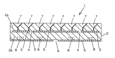
図2及び図3には道路橋の埋設型ジョイント用の埋設継手1が示されている。この埋設継手1において、2はゴム層であり、ゴム層2の中間には3枚の中間横プレート3,3,3が橋軸方向に間隙4,4をおいて埋設されている。ゴム層2の下面には2枚の下横プレート5,5が埋設継手1の中央に間隙6をおいて固着されている。
【0036】
中間横プレート3より上側の上ゴム層2aには、上からの荷重による上ゴム層2aの圧縮変形を防止するために、上面が平坦になった複数の上支持体(荷重支持体)7が前後左右(橋軸方向及び継目長手方向)に間隔をおいて設けられている。
【0037】
さらに、下横プレート5の上面には適宜数のナット8が固着され、下横プレート5の下面には各ナット8に対応するねじ孔が開口している。
【0038】
ゴム層2は、例えば硬度40〜75度程度のゴムによって形成されている。また、横プレート3,5は、鋼、プラスチック等の剛性を有する材料によって形成されている。この点は後述する他の実施形態も同様である。
【0039】
中央の中間横プレート3は、図3に示すように、継目長手方向(後述する遊間の延びる方向)の中央部が橋軸方向の両側へ山形に突出しており、そのため、相隣る中間横プレート3,3の間隙4は、継目長手方向に略「く」の字に折れ曲がって延びている。
【0040】
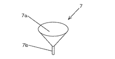
上支持体7は、下方へ行くに従って径が漸次小さくなった錐状部を有し、該錐状部の上面が平坦に形成されたものである。例えば、図4のように、上面が平坦に形成されている円錐部7aと支持脚7bを有するコマ形状のものを用いる。上支持体7の材質は、例えば、コンクリート、木、樹脂、硬質ゴム、金属等とする事ができる。図3に示すように、上支持体7はゴム層2に円錐面を下にして、適宜の間隔をおいて埋設されている。この点は後述する他の実施形態も同様である。
【0041】
また、上ゴム層2aと、中間横プレート3より下面の下ゴム層2bとは、中間横プレート3の間隙4において繋がっている。
【0042】
なお、上ゴム層2aと下ゴム層2bとが両側の中間横プレート3,3の両外側において繋がるようにしているが、両中間横プレート3,3の側面が埋設継手1の両側面に露出してもよい。埋設継手1の厚さは40mm〜150mm、橋軸方向の幅は400mm〜800mmとすることが好ましい。この点は後述する他の実施形態も同様である。
【0043】
(埋設継手の製造)
埋設継手1は次のようにして製造することができる。すなわち、下横プレート5,5を下型にセットし、この下横プレート5,5の上に生ゴムを載せる。その上に中間横プレート3,3,3を載せ、その上に生ゴムを載せ、該生ゴムに多数の上支持体7を適宜の間隔をおいて埋め込む。さらに、その上から上型を被せ、加熱加圧することによって生ゴムを中間横プレート3及び下横プレート5に加硫接着させるようにすればよい。以上により、上支持体7が中間横プレート3に固定されていない(上支持体7が横移動可能な)埋設継手1が得られる。
【0044】
(道路橋の埋設型ジョイント)
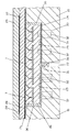
図5は上記埋設継手1を用いた埋設型ジョイントを示す。同図において、21は道路橋本体、22は道路橋本体21の伸縮を許容する遊間である。遊間22の両側では道路橋本体21に切欠き部が形成され、この切欠き部に超速硬セメント、樹脂コンクリート等の不陸調整材24が塗布されて、道路橋本体21の上面よりも低くなった段部25が形成されている。
【0045】
そうして、上記遊間22の両側の段部25,25に跨るように埋設継手1が架設されている。埋設継手1の上面は道路橋本体21の上面と同一面になっている。埋設継手1は、上記ナット8にねじ結合したアンカー32によって道路橋本体21に固定されている。また、埋設継手1と切欠き部の側面との隙間には液状ゴムシール材、セメントモルタル、樹脂モルタル等の充填材36が充填されている。
【0046】
道路橋本体21の上面及び埋設継手1の上には舗装のクラック抑制及び防水を兼ねた第1シート26が設けられ、その上に基層アスファルト舗装27が形成されている。基層アスファルト舗装27の上には舗装のクラック抑制及び防水を兼ねた第2シート28が設けられ、その上に表層アスファルト舗装29が設けられている。埋設継手1の下の遊間22には、スポンジ、発泡スチロール等によるバックアップ材30が詰められ、その上にゴムシール材31が設けられている。
【0047】
(埋設型ジョイントの施工方法)
新しい道路橋に上記埋設型ジョイントを施工する場合は、以下の手順で行なうことができる。
A.道路橋本体21,21の端部に箱抜き工法等により形成された切欠き部の底面を平坦にする(荒仕上げ)。
B.遊間22にバックアップ材30を詰め、その上に液状ゴムシール材を流し込んでシール材31を形成する。
C.切欠き部にアンカー32のための孔33を穿つ。
D.アンカー用孔33にアンカー固定材34を充填するとともに、切欠き部の底面に不陸調整材24を塗布することにより、段部25を形成する。アンカー固定材34には不陸調整材24と同じ材料を使用することができる。
E.予め埋設継手1のナット8にアンカー32をねじ結合しておき、このアンカー32をアンカー用孔33のアンカー固定材34に没入させていって埋設継手1を段部25,25に設置する。埋設継手1は必要数を継目長手方向に突き合わせて設置していく。
F.埋設継手1と切欠き部の側面との隙間に充填材36を充填する。
G.次いで、道路橋本体21の上面及び埋設継手1の上に第1シート26を貼り、その上に基層アスファルト舗装27を施し、その上に第2シート28を貼り、その上に表層アスファルト舗装29を施す。
【0048】
既設の道路橋伸縮装置を撤去して本発明の埋設型ジョイントに代える場合(所謂補修の場合)は、コンクリートカッターにより既設伸縮装置に沿ってその両側の路面に切れ目を入れ、この両切れ目の内側のコンクリートを崩して当該伸縮装置を撤去する。そうして、遊間の両側に埋設継手1の厚さに匹敵する深さの段部を形成し、後は新設の場合と同様に上記B〜Gを行なえばよい。
【0049】
(作用効果)
従って、以上のような埋設型ジョイントであれば、埋設継手1がゴム層2a,2b及び剛性横プレート3,5を積層してなるものであるから、耐荷力が高いものになり、通過する自動車の輪荷重による舗装27,29の凹みや轍ぼりが防止される。
【0050】
特に、上ゴム層2aは、上支持体7の円錐形状面との接触面積が大きいため、荷重支持力が大きくなり、輪荷重によって上ゴム層2aが圧縮変形することが防止され、舗装27,29が下方へたわむことがなくなる。よって、自動車の走行性が良好なものになるとともに、舗装27,29にクラックが入ることが抑制される。
【0051】
また、道路橋本体21の伸縮による遊間の拡大・縮小変形は、埋設継手1の伸縮によって吸収され、道路橋継目部の舗装27,29に大きな応力が作用することが防がれる。
【0052】
すなわち、道路橋本体21の伸縮に伴う遊間22の拡大・縮小変形は、ゴム層2a,2bの伸縮変形によって吸収される。その際、上記支持体7は上ゴム層2aと中間横プレート5とが橋軸方向に相対移動することを妨げないから、中間横プレート3の各々のプレート間隙4でゴム層2a,2bの伸縮変形が許容されることになる。
【0053】
また、プレート間隙4でゴム層2a,2bの変形が許容されるということは、道路橋本体21の伸縮に伴って道路橋継目部に生ずる応力が埋設継手1の両側部位(充填材36の部位)だけでなく、中間横プレート間隙4の部位にも分散されるということである。
【0054】
このように、上記埋設継手1は、プレート間隙4を設けたことにより、伸縮性が高くなっており、しかも応力の分散性が高くなっているから、道路橋本体21の伸縮を無理なく吸収することができ、舗装27,29にクラックが発生することを抑制する上で有利である。
【0055】
仮に、上記道路橋本体21の伸縮によって、複数の上支持体7の間隙に対応する部位で舗装27,29に微小クラックを生ずることがあっても、そのクラックは当該間隙形状に対応して橋軸に対して斜めに延びたものになるから、自動車のタイヤはクラックを斜めに横切ることになり、良好な走行性確保の面で有利になる。
【0056】
なお、下横プレート7の下面にゴム層を設けてもよい。この点は次の実施形態2も同様である。
【0057】
−実施形態2−
本実施形態については図6に示されており、上ゴム層2aに複数の上支持体7、下ゴム層2bに複数の下支持体9を備えていることを特徴とする。
【0058】
すなわち、同図に示す埋設継手1において、2はゴム層であり、上ゴム層2aには上支持体7が前後左右(橋軸方向及び継目長手方向)に間隔をおいて設けられている。
【0059】
下ゴム層2bには下支持体9が前後左右(橋軸方向及び継目長手方向)に間隔をおいて設けられている。
【0060】
支持体7,9を埋設後、上ゴム層2aと下ゴム層2bを加熱加圧することにより固着し、ゴム層2を形成する。
【0061】
ゴム層2の下面には2枚の継目長手方向に直線状に延びる下横プレート5,5が埋設継手1の中央に間隙6をおいて固着されている。
【0062】
下横プレート5には前後左右に適宜の間隔をおいてナット孔が形成され、このナット孔にナット8が嵌められて該下横プレート5に溶接されている。ナット8のねじ孔は当該埋設継手1の下面に開口している。
【0063】
下支持体9は、上支持体7と同等で、下方へ行くに従って径が漸次小さくなった錐状部を有し、該錐状部の上面が平坦に形成されたものである。例えば、図4のように、上面が平坦に形成されている円錐部7aと支持脚7bを有するコマ形状のものを用いる。下支持体9の材質は、上支持体7と同等で、例えば、コンクリート、木、樹脂、硬質ゴム、金属等とする事ができる。
【0064】
本実施形態の埋設継手1も実施形態1と同様にして道路橋継目部に設置し埋設型ジョイントを形成することができる。
【0065】
本実施形態においても、実施形態1と同様の作用効果が得られると共に、上ゴム層2aは上支持体7によって上からの荷重によるゴムの圧縮変形を防止し、下ゴム層2bは下支持体9によって上からの荷重によるゴムの圧縮変形を防止するため、舗装の下方へのたわみがより確実に防止され、自動車の走行性を良好なものにし、且つ舗装にクラックが入ることを避ける上で有利になる。
【0066】
また、自動車が道路橋を走行するときは、遊間22を存して相対する道路橋本体の端部同士に相対的な上下変位を生じ、従来はこの相対的な上下変位が舗装にクラックを生ずる一因となっていた。これに対して、本実施形態の場合、この上下変位によるクラック発生も抑制される。
【0067】
−その他−
なお、埋設継手は、ゴム層と横プレートとを交互に積層して横プレートが3層以上になるようにしてもよい。
【0068】
また、上記実施形態は道路橋本体同士の継目部に本発明を適用したものであるが、本発明が道路橋本体と橋台との継目部にも同様に適用できることはもちろんである。
【図面の簡単な説明】
【図1】従来の道路橋継目部構造の一例を示す断面図。
【図2】本発明の実施形態1に係る埋設継手の断面図。
【図3】同埋設継手の荷重支持体の配置と中間横プレートを示す平面図。
【図4】荷重支持体の形状を示す斜視図。
【図5】同実施形態の埋設型ジョイントを示す一部省略した断面図。
【図6】本発明の実施形態2に係る埋設継手の断面図。
【符号の説明】
1 埋設継手
2 ゴム層
2a 上ゴム層
2b 下ゴム層
3 中間横プレート
4 プレート間隙
5 下横プレート
6 プレート間隙
7 上支持体
7a 円錐部
7b 支持脚
8 ナット
9 下支持体
21 道路橋本体
22 遊間
24 不陸調整材
25 段部
26 第1シート
27 基層アスファルト舗装
28 第2シート
29 表層アスファルト舗装
30 バックアップ材
31 ゴムシール材
32 アンカー
33 孔
34 アンカー固定材
36 充填材[0001]
TECHNICAL FIELD OF THE INVENTION
The present invention relates to a buried joint for a buried joint of a road bridge and a buried joint of a road bridge.
[0002]
[Prior art]
The buried joint is mainly applied to a road bridge having a relatively small amount of expansion and contraction, and is known to absorb the expansion and contraction of a road bridge body by deformation of a continuously paved pavement material. Its basic structure is shown in FIG. That is, on both sides of the road bridge play space a, a step c is formed at the end of the road bridge body b, and the play a is filled with the joint material d, and the step material c is placed on the step c so as to cover the joint material d. An elastic compound e is cast, a waterproof sheet f is laid thereon, and a pavement g is provided thereon.
[0003]
Regarding the buried joint, a factory-made prefabricated pavement member (a pavement material layer is provided in the upper layer, and a pair of support plates separated to the left and right with a gap in the lower layer, without using the elastic compound). There is one in which a pair of support plates are fixed to the road bridge main body on both sides of the play (see, for example, Patent Document 1).
[0004]
A buried joint made by bonding a rubber plate and a steel plate under the pavement of the buried joint (a single steel plate is provided in the upper layer, and a pair of rubber plates separated to the left and right are provided in the lower layer) There is one in which a pair of rubber plates are fixed to the road bridge main body on both sides of the play (see
[0005]
[Patent Document 1]
Japanese Patent Publication No. 60-39801 [Patent Document 2]
Japanese Patent Publication No. 60-9605
[Problems to be solved by the invention]
According to the above-mentioned buried joint, the pavement is continuous without interruption at the road bridge joint, so that the running performance of the vehicle is good and the vibration and noise are reduced, but the pavement is wavy due to the flow of the elastic compound e. There is a problem that the pavement on the play area is easily cracked due to the relative vertical displacement of the road bridge body facing the play area and the expansion and contraction of the road bridge body. The cracks extend in the seam longitudinal direction (the direction intersecting with the bridge axis), so that the traveling performance of the automobile is deteriorated. In addition, the pavement breaks from the cracked part due to the impact of passing through the car, and the cracked part gradually becomes large grooves, worsening the traveling performance, increasing noise and vibration, and impairing traveling safety. Come.
[0007]
In addition, since the elastic compound e is formed of a mixture of rubber, asphalt and crushed stone, the road bridge body has poor elasticity absorption and stress dispersibility. Also, at the time of construction, first, a required amount of solid rubber and asphalt (or asphalt containing sheet-like rubber) is melted by heating in a melting tank at the site, and this melted material is further charged into a mixer together with crushed stone and mixed again by heating. It is necessary, the preparation on site is large and troublesome, and it takes time and effort. Also, even after casting on the step c, the waterproof sheet f cannot be constructed or paved g until the elastic compound e cools and solidifies. For this reason, the construction time is long, and it is not possible to complete the construction only by one night work or daytime work, and the work is interrupted in the early morning or evening and the asphalt mixture is temporarily packed by the pavement thickness. Then, the lining plate is put on the joint of the road bridge to temporarily restore the road (allowing road traffic), and the next night or day must be continued. Accordingly, the period of traffic regulation for construction is doubled, the cost is increased, and traffic safety is hindered.
[0008]
On the other hand, if the prefabricated pavement member described in Japanese Patent Publication No. 60-39801 is used, the problem of the elastic compound can be solved, but the pavement material layer of the pavement member is similar to the elastic compound. Almost no elasticity. Therefore, if the play space is enlarged or reduced due to expansion and contraction of the road bridge main body, cracks are generated in the pavement material layer between the left and right support plates, and the cracks spread to the pavement on the pavement member.
[0009]
In the case of a buried joint comprising a pair of rubber plates and a steel plate described in Japanese Patent Publication No. 60-9605, although the rubber plates allow the expansion and contraction of the road bridge main body, the steel plates hinder the expansion and contraction of the road bridge main body. Therefore, there is a problem that cracks occur on the pavement on both sides of the steel sheet.
[0010]
Further, in the case of this buried joint, when a large load is applied from above as the vehicle passes, there is a problem that the rubber plate is compressed and deformed and the pavement is bent downward. In other words, such pavement deflection deteriorates the traveling performance of the car, and the phenomenon that the pavement bends and returns to the original state each time the car passes is repeated, so that the pavement itself originally has elasticity and flexibility. Since there is almost no flexibility, cracks tend to occur on the pavement.
[0011]
An object of the present invention is to suppress the occurrence of cracks on the pavement in such a buried joint.
[0012]
Another object of the present invention is to improve the running performance of an automobile.
[0013]
[Means for Solving the Problems]
In order to solve such problems, the present invention embeds a plurality of load supports in a rubber layer when forming an embedded joint using rubber, and obtains elasticity in a bridge axis direction while applying a load from above. The compression deformation of rubber is prevented.
[0014]
That is, the invention according to claim 1 is laid so as to straddle the road bridge main body on both sides of the play of the road bridge joint portion or to straddle the road bridge main body and the abutment on both sides of the play, and is buried under the pavement. A buried joint for a buried joint of a road bridge,
Rubber layer,
A plurality of load supports that are embedded in the rubber layer at intervals in the bridge axis direction and have a flat top surface that receives a load from above,
Under the plurality of load supports in the rubber layer, a plurality of load receiving plates are provided at intervals in the bridge axis direction and receive a load from above via the load supports. It is characterized by.
[0015]
Therefore, since the buried joint is formed by laminating rubber and a plate, plastic flow does not occur, and dent or rut on the pavement surface due to the wheel load of the automobile is prevented.
[0016]
There are two important features in the present invention, one of which is a plurality of load supports which are embedded in the rubber layer at intervals in the bridge axis direction and have a flat upper surface which receives a load from above. However, the point is that the compression deformation of the rubber due to the load from above is suppressed.
[0017]
Therefore, even if a large wheel load acts on the buried joint as the vehicle passes, the rubber layer in which the load support is buried can be prevented from being compressed and deformed, whereby the pavement is prevented from sagging downward. You. Therefore, the driving performance of the automobile is improved.
[0018]
In addition, since the plurality of load supports are provided at intervals in the bridge axis direction, the elasticity of the rubber body is not impaired, and cracks can be avoided in the pavement.
[0019]
Another important feature of the present invention is that a plurality of horizontal plates provided at intervals in the bridge axis direction and rubber are laminated, so that the gap is increased in the bridge axis direction as the rubber layer is deformed. The point is that the adjacent horizontal plates are relatively displaced.
[0020]
That is, if there is only one horizontal plate, the rubber layer provided thereunder only causes shear deformation, but in the case of the present invention, a plurality of horizontal plates are spaced apart in the bridge axis direction. Therefore, the elastic deformation of the rubber layer between the plates is allowed. In addition, the fact that deformation of the rubber layer is allowed between the plates of the plurality of horizontal plates means that the stress generated at the seam of the road bridge due to the expansion and contraction of the road bridge body is not only at both sides of the buried joint, but also between the plates. That is, it is also distributed to parts. That is, the dispersibility of the stress is high.
[0021]
In addition, the work of heating and mixing at the site like a conventional elastic compound is not required in the construction, and the construction can be completed in a short time since the pavement construction can be started immediately after the buried joint is constructed. It is possible to prevent traffic accidents and reduce construction costs.
[0022]
Further, the expansion joint includes a rubber layer,
A plurality of intermediate horizontal plates embedded in the middle of the rubber layer and provided at intervals in the bridge axis direction;
In the direction of the bridge axis, fixed to the lower surface of the rubber layer and supported by the road bridge main bodies on both sides of the gap of the road bridge joint, or supported by the road bridge main body and the abutment on both sides of the gap. Two lower horizontal plates provided at an interval,
The rubber layer is embedded in the rubber layer at intervals in the bridge axis direction, has a flat upper surface receiving a load from above, and includes a plurality of load supports embedded above the middle of the rubber layer. It may be one characterized by that.
[0023]
The number of horizontal plates provided at intervals in the bridge axis direction may be two, but it is preferable to arrange three or more in parallel.
[0024]
The upper surface of the load support is formed flat, but is not necessarily smooth, and may have minute irregularities.
[0025]
The invention according to
The load support has a conical portion whose diameter gradually decreases as it goes downward, and the upper surface of the conical portion is formed flat.
[0026]
Therefore, since the load support has a conical portion whose diameter gradually decreases as it goes downward, the contact area between the rubber layer and the conical surface is large, so that the load supporting force increases, The rubber layer is prevented from being compressed and deformed by the load of the pavement, and the pavement does not bend downward. Therefore, the traveling property of the automobile is improved, and cracks are prevented from being formed on the pavement.
[0027]
The invention according to
Rubber layer,
It has a conical portion whose diameter gradually decreases as it goes downward, and a load support body in which the upper surface of the conical portion is formed flat,
The plurality of load supports are embedded in the rubber layer at intervals in the bridge axis direction, and are provided in layers at upper and lower intervals.
[0028]
Also, the bridge axle is fixed to the lower surface of the rubber layer and supported by the road bridge main body on both sides of the play at the seam of the road bridge, or supported by the road bridge main body and the abutment on both sides of the play. Two lower horizontal plates provided at intervals in the direction may be provided.
[0029]
Therefore, according to the present invention, the upper rubber layer prevents the compression deformation of the rubber due to the load from above by the upper support, and the lower rubber layer prevents the load from above by the lower support. As a result, the downward deformation of the pavement is more reliably prevented, the running property of the automobile is improved, and cracks are prevented from entering the pavement.
[0030]
In the invention according to claim 4, a step portion lower than the upper surface of the road bridge main body is formed on the road bridge main body on both sides of the play of the road bridge joint, or on the road bridge main body and the abutment on both sides of the play,
The buried joint according to any one of claims 1 to 3 is erected so as to straddle the steps on both sides of the play,
A continuous pavement is provided on the buried joint.
[0031]
Therefore, according to the present invention, as apparent from the description of the first to third aspects of the present invention, it is possible to suppress the occurrence of cracks and irregularities on the pavement, and to improve the traveling property of the automobile. Become.
[0032]
【The invention's effect】
As described above, according to the present invention, since a plurality of load supports having a flat upper surface are buried at intervals in the bridge axis direction, the rubber layer is prevented from being deformed in a compressed manner, so that the vehicle wheel is prevented from being deformed. Prevents pavement deflection due to load, increases the elasticity of the buried joints, and is advantageous in suppressing cracks in the pavement. Can be greatly reduced.
[0033]
Further, by burying a large number of load supports, the amount of rubber used for the rubber layer is reduced, and the material cost of the buried joint is reduced.
[0034]
BEST MODE FOR CARRYING OUT THE INVENTION
Hereinafter, embodiments of the present invention will be described with reference to the drawings.
[0035]
-Embodiment 1-
(Buried joint)
2 and 3 show a buried joint 1 for a buried joint of a road bridge. In this embedded joint 1,
[0036]
In order to prevent the upper rubber layer 2a from being compressed and deformed by a load from above, a plurality of upper supports (load supports) 7 having a flat upper surface are provided on the upper rubber layer 2a above the intermediate
[0037]
Further, an appropriate number of
[0038]
The
[0039]
As shown in FIG. 3, the central intermediate
[0040]
The
[0041]
The upper rubber layer 2 a and the
[0042]
Although the upper rubber layer 2a and the
[0043]
(Manufacture of buried joints)
The buried joint 1 can be manufactured as follows. That is, the lower
[0044]
(Buried joints for road bridges)
FIG. 5 shows a buried joint using the buried joint 1. In the figure,
[0045]
The buried joint 1 is erected so as to straddle the
[0046]
A
[0047]
(Construction method of buried joint)
When installing the above buried joint on a new road bridge, the following procedure can be used.
A. The bottoms of the notches formed at the ends of the
B. The
C. A
D. The
E. FIG. The
F. The
G. FIG. Next, the
[0048]
When removing the existing road bridge expansion / contraction device and replacing it with the buried joint of the present invention (so-called repair), a cut is made on the road surface on both sides thereof along the existing expansion / contraction device with a concrete cutter, Collapse the concrete and remove the telescopic device. Then, a step having a depth equivalent to the thickness of the buried joint 1 is formed on both sides of the play, and the above steps B to G may be performed in the same manner as in the case of the new construction.
[0049]
(Effect)
Accordingly, in the case of the buried joint as described above, since the buried joint 1 is formed by laminating the rubber layers 2a and 2b and the rigid
[0050]
In particular, since the upper rubber layer 2a has a large contact area with the conical surface of the
[0051]
In addition, the expansion / contraction deformation of the play due to the expansion and contraction of the
[0052]
That is, the expansion / contraction deformation of the
[0053]
In addition, the deformation of the rubber layers 2a and 2b is allowed in the plate gap 4, which means that the stress generated at the seam of the road bridge due to the expansion and contraction of the
[0054]
As described above, the buried joint 1 has a high elasticity due to the provision of the plate gap 4 and a high dispersibility of stress, so that the expansion and contraction of the road bridge
[0055]
Even if the
[0056]
Note that a rubber layer may be provided on the lower surface of the lower
[0057]
-
This embodiment is shown in FIG. 6 and is characterized in that a plurality of
[0058]
That is, in the buried joint 1 shown in the figure,
[0059]
A
[0060]
After the
[0061]
On the lower surface of the
[0062]
Nut holes are formed in the lower
[0063]
The
[0064]
The buried joint 1 of the present embodiment can also be installed at the joint of the road bridge in the same manner as in the first embodiment to form a buried joint.
[0065]
Also in this embodiment, the same operation and effect as those of the first embodiment can be obtained, the upper rubber layer 2a prevents the rubber from being compressed and deformed by the load from above by the
[0066]
Also, when a car travels on a road bridge, a relative vertical displacement occurs between the ends of the road bridge main body facing each other with a
[0067]
−Others−
In the buried joint, the rubber plate and the horizontal plate may be alternately laminated so that the horizontal plate has three or more layers.
[0068]
In the above-described embodiment, the present invention is applied to the joint between the road bridge bodies. However, it is needless to say that the present invention can be similarly applied to the joint between the road bridge main body and the abutment.
[Brief description of the drawings]
FIG. 1 is a cross-sectional view showing an example of a conventional road bridge joint structure.
FIG. 2 is a cross-sectional view of the buried joint according to the first embodiment of the present invention.
FIG. 3 is a plan view showing an arrangement of a load support of the buried joint and an intermediate horizontal plate.
FIG. 4 is a perspective view showing the shape of a load support.
FIG. 5 is a partially omitted cross-sectional view showing the embedded joint of the embodiment.
FIG. 6 is a sectional view of a buried joint according to a second embodiment of the present invention.
[Explanation of symbols]
DESCRIPTION OF SYMBOLS 1 Embedded joint 2 Rubber layer 2a
Claims (4)
ゴム層と、
上記ゴム層に橋軸方向へ間隔をおいて埋設され、上からの荷重を受ける上面が平坦な形状である複数の荷重支持体と、
上記ゴム層における上記複数の荷重支持体の下側に、橋軸方向へ間隔をおいて設けられ、上記荷重支持体を介して上からの荷重を受ける複数の荷重受けプレートとを備えていることを特徴とする道路橋の埋設型ジョイント用の埋設継手。A buried joint for a buried type joint of a road bridge that is laid so as to straddle the road bridge body on both sides of the gap of the road bridge seam or between the road bridge body and the abutment on both sides of the gap and buried under the pavement And
Rubber layer,
A plurality of load supports that are embedded in the rubber layer at intervals in the bridge axis direction and have a flat top surface that receives a load from above,
Under the plurality of load supports in the rubber layer, a plurality of load receiving plates are provided at intervals in the bridge axis direction and receive a load from above via the load supports. A buried joint for a buried joint of a road bridge, characterized by:
上記荷重支持体は、下方へ行くに従って径が漸次小さくなった錐状部を有し、該錐状部の上面が平坦に形成されていることを特徴とする道路橋の埋設型ジョイント用の埋設継手。In claim 1,
The above-mentioned load support has a conical portion whose diameter becomes gradually smaller as it goes downward, and the upper surface of the conical portion is formed flat. Fittings.
ゴム層と、
下方へ行くに従って径が漸次小さくなった錐状部を有し、該錐状部の上面が平坦に形成されている荷重支持体とを備え、
上記複数の荷重支持体は、上記ゴム層に橋軸方向へ間隔をおいて埋設されているとともに、上下に間隔をおいて層状に設けられていることを特徴とする道路橋の埋設型ジョイント用の埋設継手。A buried joint for a buried type joint of a road bridge that is laid so as to straddle the road bridge body on both sides of the gap of the road bridge seam or between the road bridge body and the abutment on both sides of the gap and buried under the pavement And
Rubber layer,
It has a conical portion whose diameter gradually decreases as it goes downward, and a load support body in which the upper surface of the conical portion is formed flat,
The above-mentioned plurality of load supports are embedded in the rubber layer at intervals in the bridge axis direction, and are provided in layers at intervals vertically, for an embedded joint of a road bridge. Buried fittings.
上記遊間両側の段部に跨るように請求項1乃至請求項3のいずれかに記載の埋設継手が架設され、
上記埋設継手の上に連続舗装がされていることを特徴とする道路橋の埋設型ジョイント。Steps that are lower than the upper surface of the road bridge main body are formed on the road bridge main body on both sides of the play of the road bridge joint, or on the road bridge main body and the abutment on both sides of the play,
The buried joint according to any one of claims 1 to 3 is erected so as to straddle the steps on both sides of the play,
A buried joint for a road bridge, wherein a continuous pavement is provided on the buried joint.
Priority Applications (1)
| Application Number | Priority Date | Filing Date | Title |
|---|---|---|---|
| JP2002259134A JP3672899B2 (en) | 2002-09-04 | 2002-09-04 | Buried joints for road bridge buried joints and buried bridge joints for road bridges |
Applications Claiming Priority (1)
| Application Number | Priority Date | Filing Date | Title |
|---|---|---|---|
| JP2002259134A JP3672899B2 (en) | 2002-09-04 | 2002-09-04 | Buried joints for road bridge buried joints and buried bridge joints for road bridges |
Publications (2)
| Publication Number | Publication Date |
|---|---|
| JP2004100151A true JP2004100151A (en) | 2004-04-02 |
| JP3672899B2 JP3672899B2 (en) | 2005-07-20 |
Family
ID=32260264
Family Applications (1)
| Application Number | Title | Priority Date | Filing Date |
|---|---|---|---|
| JP2002259134A Expired - Lifetime JP3672899B2 (en) | 2002-09-04 | 2002-09-04 | Buried joints for road bridge buried joints and buried bridge joints for road bridges |
Country Status (1)
| Country | Link |
|---|---|
| JP (1) | JP3672899B2 (en) |
Cited By (1)
| Publication number | Priority date | Publication date | Assignee | Title |
|---|---|---|---|---|
| JP2009180008A (en) * | 2008-01-31 | 2009-08-13 | Nitta Ind Corp | Simple steel vertical telescopic device for road bridges |
-
2002
- 2002-09-04 JP JP2002259134A patent/JP3672899B2/en not_active Expired - Lifetime
Cited By (1)
| Publication number | Priority date | Publication date | Assignee | Title |
|---|---|---|---|---|
| JP2009180008A (en) * | 2008-01-31 | 2009-08-13 | Nitta Ind Corp | Simple steel vertical telescopic device for road bridges |
Also Published As
| Publication number | Publication date |
|---|---|
| JP3672899B2 (en) | 2005-07-20 |
Similar Documents
| Publication | Publication Date | Title |
|---|---|---|
| CN104652268B (en) | A kind of bridge deck continuous seam structure and forming method thereof | |
| JP2007138467A (en) | Load bearing type expansion device of elevated road and its construction method | |
| JP2007309032A (en) | Continuous structure of bridge joints | |
| CN115538295B (en) | A novel structure and construction method of combined telescopic device | |
| RU2681044C1 (en) | Deformation joint of bridge | |
| JP3672899B2 (en) | Buried joints for road bridge buried joints and buried bridge joints for road bridges | |
| JP3693632B2 (en) | Buried joints for road bridge buried joints and buried bridge joints for road bridges | |
| JP3789412B2 (en) | Buried joints for road bridge buried joints and buried bridge joints for road bridges | |
| JP3720003B2 (en) | Buried joints for road bridge buried joints and buried bridge joints for road bridges | |
| JP3660905B2 (en) | Road bridge joint structure | |
| JP2763455B2 (en) | Paved version | |
| JP2009007790A (en) | Bridge compound steel floor slab applied with mma resin mortar applied | |
| JP3727057B2 (en) | Structure of buried joints in bridges | |
| EP1262601B1 (en) | Bridging material for a joint construction as well as prefabricated bridging unit | |
| JP2000129616A (en) | Damage prevention construction of continuous bridge- like structure | |
| JPS6149444B2 (en) | ||
| JPH06146206A (en) | Pavement on bridge surface and continuous pavement method on bridge surface | |
| CN211645814U (en) | Road and bridge section with sectional gap filling material | |
| JP2002309509A (en) | Structure of highway bridge joint part | |
| JPS5929727B2 (en) | road joint | |
| JP2923586B2 (en) | Expansion joint structures for bridges and roads | |
| JPH0791803B2 (en) | Road joint | |
| JP2003041510A (en) | Structure of road bridge joint | |
| EP1496156A2 (en) | Railway construction | |
| JPH03208902A (en) | Road joint section exclusive paving material |
Legal Events
| Date | Code | Title | Description |
|---|---|---|---|
| A977 | Report on retrieval |
Free format text: JAPANESE INTERMEDIATE CODE: A971007 Effective date: 20041029 |
|
| A131 | Notification of reasons for refusal |
Free format text: JAPANESE INTERMEDIATE CODE: A131 Effective date: 20041130 |
|
| A521 | Request for written amendment filed |
Free format text: JAPANESE INTERMEDIATE CODE: A523 Effective date: 20050125 |
|
| TRDD | Decision of grant or rejection written | ||
| A01 | Written decision to grant a patent or to grant a registration (utility model) |
Free format text: JAPANESE INTERMEDIATE CODE: A01 Effective date: 20050322 |
|
| A61 | First payment of annual fees (during grant procedure) |
Free format text: JAPANESE INTERMEDIATE CODE: A61 Effective date: 20050420 |
|
| R150 | Certificate of patent or registration of utility model |
Ref document number: 3672899 Country of ref document: JP Free format text: JAPANESE INTERMEDIATE CODE: R150 Free format text: JAPANESE INTERMEDIATE CODE: R150 |
|
| FPAY | Renewal fee payment (event date is renewal date of database) |
Free format text: PAYMENT UNTIL: 20080428 Year of fee payment: 3 |
|
| FPAY | Renewal fee payment (event date is renewal date of database) |
Free format text: PAYMENT UNTIL: 20090428 Year of fee payment: 4 |
|
| R250 | Receipt of annual fees |
Free format text: JAPANESE INTERMEDIATE CODE: R250 |
|
| FPAY | Renewal fee payment (event date is renewal date of database) |
Free format text: PAYMENT UNTIL: 20090428 Year of fee payment: 4 |
|
| FPAY | Renewal fee payment (event date is renewal date of database) |
Free format text: PAYMENT UNTIL: 20110428 Year of fee payment: 6 |
|
| R250 | Receipt of annual fees |
Free format text: JAPANESE INTERMEDIATE CODE: R250 |
|
| FPAY | Renewal fee payment (event date is renewal date of database) |
Free format text: PAYMENT UNTIL: 20110428 Year of fee payment: 6 |
|
| FPAY | Renewal fee payment (event date is renewal date of database) |
Free format text: PAYMENT UNTIL: 20140428 Year of fee payment: 9 |
|
| R250 | Receipt of annual fees |
Free format text: JAPANESE INTERMEDIATE CODE: R250 |
|
| R250 | Receipt of annual fees |
Free format text: JAPANESE INTERMEDIATE CODE: R250 |
|
| R250 | Receipt of annual fees |
Free format text: JAPANESE INTERMEDIATE CODE: R250 |
|
| S111 | Request for change of ownership or part of ownership |
Free format text: JAPANESE INTERMEDIATE CODE: R313113 |
|
| R350 | Written notification of registration of transfer |
Free format text: JAPANESE INTERMEDIATE CODE: R350 |
|
| R250 | Receipt of annual fees |
Free format text: JAPANESE INTERMEDIATE CODE: R250 |
|
| EXPY | Cancellation because of completion of term |