【0001】
【発明の属する技術分野】
本発明は、主に、鋼構造建築物を構成する円形鋼管柱にH形断面梁をスプリットティやアングル材などの接合金物を介して高力ボルト接合する円形鋼管柱とH形断面梁の高力ボルト接合構造および接合金物に関するものである。
【0002】
【従来の技術】
従来、例えば、角形鋼管柱とH形鋼梁を対象とした柱−梁接合部形式では、例えば特開平11−269986号公報などによって、図10(a)、(b)、(c)に示すように、上下一対のスプリットティ2a、2bと高力ボルト3、5を用いた角形鋼管柱1とH形鋼梁4の高力ボルト接合構造が知られている。
この接合構造においては、角形鋼管柱1の各側部に、それぞれ、上下一対のスプリットティ2a、2bのフランジ2fを高力ボルト3で接合し、この上下のスプリットティ2a、2bのウエブ2u間にH形鋼梁4の端部を位置させ、上スプリットティ2aの水平板2pの下面側にH形鋼梁4の上フランジ4aの上面を、また、下スプリットティ2bのウエブ2uの上面側にH形鋼梁4の下フランジ4bの上面を当接して高力ボルト5で接合する、溶接負担を軽減した角形鋼管柱とH形鋼梁の高力ボルト接合構造が一般的に知られている。ここで用いるスプリットティ2a、2bとしては、T形断面で、H形鋼をそのウエブで長さ方向に切断して得られるもの、板をT形に溶接組み立てして得られるもの、あるいは鋳物製作によって得られるT形材が知られている。
また、図11(a)、(b)に示すように、スプリットティ2a、2bに代えて、上側の上下一対のアングル材7aと7b、下側の上下一対のアングル材7cと7dと高力ボルト3、5を用いた角形鋼管柱1とH形鋼梁4の高力ボルト接合構造も知られている。
この接合構造では、角形鋼管柱1の側部に、向きを反対にして配置した上側の上下一対のアングル材7aと7b、下側の上下一対のアングル材7cと7dのフランジ2fを、それぞれ高力ボルト3で接合し、H形鋼梁4の上フランジ4aに、上側の上下一対のアングル材7aと7bのウエブ7uを上下から挟み込むように当接して高力ボルト5により接合し、H形鋼梁4の下フランジ4bに下側の上下一対のアングル材7cと7dのフランジ2fを上下から挟み込むように当接して高力ボルト5により接合するものである。ここで用いるアングル材7aと7b、7cと7dとしては、不等辺山形鋼を幅方向に切断して得られるL形材が知られている。
【0003】
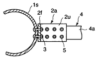
一方、図12に示すように、上下一対のスプリットティ2a、2bと高力ボルト3、5を用いた円形鋼管柱1sとH形鋼梁4の高力ボルト接合構造が知られている。この接合構造において、図10に示すような上下スプリットティ2a、2bを用いた場合には、スプリットティの平坦なフランジ2f面を曲面の円形鋼管柱1sに当接するため、1線の線接触になるため、密着性確保に難点があり、高力ボルト3による接合しても十分な接合部性能が得られないことから、接合金物として、例えば、
(1)図13に示すように、円形鋼管柱1sの曲面にフィットする曲面のフランジ8fとウエブ8uを有する鋳物製作された異形T形材または曲げ加工と溶接により製作されたされた異形T形材8を使用する。
(2)図14に示すように、図10に示すような角形鋼管柱1を対象として用いられるT形断面のスプリットティ2a(2b)と、円形鋼管柱1sとの密着性を確保するために円形鋼管柱1sの曲面にフィットする曲面を有する特殊形状の金物9a、9bを使用する。
などの提案がなされている。
しかし、(1)の鋳物製作によるものは、特殊材料を用いるため、強度的にも制限がある上、角形鋼管のように平面接触ではないので、円形鋼管のRによるサイズバリエーションが必要であり、コスト高のものになるという問題もある。
また、(1)の曲げ加工と溶接によるものは、板の曲げ加工や溶接が必要であり、加工負担が大きく、コスト高のものになるという問題がある。(2)のものは、T形断面のスプリットティと特殊形状の金物を併用する必要があり、材料、および製作コスト負担増に加え施工性にも問題がある。
【0004】
【発明が解決しようとする課題】
本発明は、T形接合金物やL形接合金物などの接合金物と高力ボルトを用いる円形鋼管柱とH形鋼梁の高力ボルト接合構造において、接合部性能(剛性、耐力)を安定確保でき、コスト負担を軽減できる特殊形状の接合金物を用いた円形鋼管柱とH形断面梁の高力ボルト接合構造と、この接合構造で用いる接合金物を提供するものである。
【0005】
【課題を解決するための手段】
本発明は、上記の目的を達成するために、以下の(1)〜(7)を要旨とするものである。
(1).円形鋼管柱と接合する垂直板(フランジ)とH形断面梁と接合する水平板(ウエブ)を有するT形接合金物と高力ボルトを用いた円形鋼管柱とH形断面梁の高力ボルト接合構造において、円形鋼管柱の上下に所定間隔をおいて接合するT形接合金物を、H形断面梁と平行に並列配置した傾斜フランジを有する左右一対の異形T形材で形成し、この左右一対の異形T形材のフランジを、それぞれ、円形鋼管柱に当接し、この当接部または当接部近傍領域において円形鋼管柱の中心に向くように挿通した高力ボルトで円形鋼管柱と一対の異形T形材のフランジを締結・接合し、H形断面梁の上下フランジを、それぞれ、左右一対の異形T形材のウエブに高力ボルト接合するようにしたことを特徴とする円形鋼管柱とH形断面梁の高力ボルト接合構造。
(2).円形鋼管柱と接合する垂直板(フランジ)とH形断面梁と接合する水平板(ウエブ)を有するL形接合金物と高力ボルトを用いた円形鋼管柱とH形断面梁の高力ボルト接合構造において、円形鋼管柱の上下に所定の間隔をおいて接合するL形接合金物を、H形断面梁と平行に並列配置した傾斜フランジを有する左右一対の異形L形材で形成して、この左右一対の異形L形材を、H形断面梁の上フランジと下フランジに対して、それぞれ、向きを反対にしてウエブを上下から当接するように上下一対配置して、それぞれのフランジを円形鋼管柱に当接し、この当接部または当接部近傍領域において円形鋼管柱の中心に向くように挿通した高力ボルトで円形鋼管柱と異形L形材のフランジを締結・接合し、H形断面梁の上下フランジを、それぞれ、左右一対、上下一対の異形L形材のウエブに高力ボルト接合するようにしたことを特徴とする円形鋼管柱とH形断面梁の高力ボルト接合構造。
(3).(1)において、並列配置された左右一対の異形T形材の円形鋼管柱に当接される側のフランジ面が、高力ボルトの挿通方向に対して直角な面に形成されていることを特徴とする円形鋼管柱とH形断面梁の高力ボルト接合構造。
(4).(2)において、並列配置された左右一対の異形L形材の円形鋼管柱に当接される側のフランジ面が、高力ボルトの挿通方向に対して直角な面に形成されていることを特徴とする円形鋼管柱とH形断面梁の高力ボルト接合構造。
(5).(1)〜(4)のいずれかにおいて、円形鋼管柱の曲面側に当接する座金が、円形鋼管柱の曲面に合う曲面に形成した座面を有することを特徴とする円形鋼管柱とH形断面梁の高力ボルト接合構造。
(6).H形断面材を幅方向に斜めに切断し、ウエブをフランジ面に平行に切断して、円形鋼管柱に接するフランジ面をウエブ側端面に対して斜めに形成した異形T形材であり、この異形T形材を平行に左右に並列配置する際には、左右一対の異形T形材のフランジ面が鈍角のV字を形成するように配置するものであることを特徴とするT形接合金物形成用の異形T形材。
(7).山形断面材を幅方向に斜めに切断して、円形鋼管柱に接するフランジ面を、ウエブ側端面に対して斜めに形成した異形L形材であり、この異形L形材を平行に左右に並列配置する際には、左右一対の異形T形材のフランジ面が鈍角のV字を形成するように配置するものであることを特徴とするL形接合金物形成用の異形L形材。
【0006】
【発明の実施の形態】
本発明は、スプリットティなどのT形接合金物やアングル材などのL形接合金物と引張高力ボルトを用いた、円形鋼管柱などの円形鋼管柱とH形鋼梁などのH形断面梁の高力ボルト接合構造において適用されるものである。
本発明の円形鋼管柱とH形断面梁の高力ボルト接合構造においては、円形鋼管柱の上下に接合する接合金物として、基本的にはT形接合金物を用いる場合と、L形接合金物を用いる場合がある。
【0007】
T形接合金物を用いる場合には、T形接合金物を、H形断面梁と平行に並列配置した平坦な傾斜フランジ面を有する左右一対の異形T形材で形成し、この左右一対の異形T形材のフランジ面を円形鋼管柱に当接し、この当接部または当接部近傍領域において円形鋼管柱の中心に向くように挿通した高力ボルトで円形鋼管柱と一対の異形T形材のフランジを締結・接合し、H形断面梁の上下フランジを、それぞれ、左右一対の異形T形材のウエブに高力ボルト接合するものである。また、L形接合金物を用いる場合には、L形接合金物を、左右一対、上下一対の異形L形材で形成し、H形断面梁の上フランジと下フランジに対して、上下から当接するように、向きを反対にして上下に一対配置して、それぞれのフランジを円形鋼管柱の上下に当接して、この当接部または当接部近傍領域において円形鋼管柱の中心に向くように挿通した高力ボルトで円形鋼管柱と締結・接合し、H形断面梁の上下の各フランジを、それぞれ、左右一対、上下一対の異形L形材のウエブ間に高力ボルト接合するようにするものである。
【0008】
本発明では、基本的には、接合金物として、従来の接合金物とは異なる、平坦な傾斜フランジ面を有する一対の小幅の異形T形材または異形L形材を左右に並列配置して用いるものであり、一対の異形T形材または異形L形材の傾斜フランジ面がV字を形成するように斜めに向き合うように配置して、一対の異形T形材または異形L形材の傾斜フランジ面を円形鋼管柱に線接触により当接し、この当接部または当接部近傍領域において高力ボルト接合し、H形断面梁を高力ボルト接合した状態で円形鋼管柱との接合を安定させ、接合性能を安定確保し、また、コスト負担を軽減するものである。
本発明で用いる接合金物を形成する異形T形材または異形L形材は、円形箱形断面の曲面に平坦面に形成したフランジ面を当接することを前提とするものであり、異形T形材または異形L形材を、従来公知のT形またはL形の接合金物と同様の幅で形成して単独で用いた場合には、従来公知のT形またはL形の接合金物を用いたと同様、フランジ面と円形箱形断面の曲面との接触が一線の線接触になり、安定した接合が困難である。
そこで、本発明では、異形T形材または異形L形材の幅を従来の接合金物の幅の半分程度にして、円形断面柱に当接するフランジを斜めに形成し、この左右一対の異形T形材のフランジを円形断面柱に当接したとき、この左右一対の異形T形材のフランジ面が鈍角のV字を形成して向き合うように配置して、左右一対の異形T形材または異形L形材のフランジを、円形断面柱との当接部で高力ボルト接合するものである。この際、高力ボルトは、接合を安定させるために円形鋼管柱の中心を向くように挿通するものであり、左右一対の異形T形材または異形L形材のフランジ面が高力ボルトの挿通方向に対して、直角な面を形成するようにフランジの傾斜角度を設定することが好ましい。
【0009】
なお、円形鋼管柱の曲面に異形T形材または異形L形材のフランジを接合する場合に、高力ボルト1本の挿通部単位で、円形鋼管柱の曲面と異形T形材または異形L形材のフランジの間に円形鋼管柱の曲面に合う曲面を形成した座金を介挿して当接状態を安定確保することも考慮できる。また、円形鋼管柱の内部側では、円形鋼管柱の曲面とボルトの頭部やナットとの間において、1本の高力ボルト挿通部単位で円形鋼管柱の曲面に合う曲面に形成した座金を介挿して当接状態を安定確保することも考慮することができる。
これらの座金の形状は、基本的には、円形鋼管柱との接触面の反対側の面、すなわち異形T形材または異形L形材のフランジ面との接触面、ボルトの頭部やナットとの接触面は平坦面に形成することが望ましい。
こうすることにより、左右一対の異形T形材または異形L形材のフランジ面と円形鋼管柱を高力ボルト挿通部単位で、座金を介して面接触をせることができ、安定した接合部性能を発揮させることができる。特に、円形鋼管柱と異形T形材または異形L形材のフランジ間に座金を介挿した場合には、異形T形材または異形L形材のフランジの先端部と円形鋼管柱の接触およびそれに起因するてこ反力がなくなりボルトの負荷を低減させるメリットもある。
本発明で用いる異形T形材は、例えばH形鋼を幅方向に斜め切断し、ウエブ中心部をフランジ面と並行に切断することによって容易に得ることができ、円形鋼管柱のサイズ、H形断面柱のサイズを考慮して所定のサイズのH形鋼を選択して、斜め切断する際の異形T形材の幅、フランジの傾斜角度を設定することによって、円形鋼管柱のサイズ、H形断面柱のサイズに応じた異形T形材を容易に得ることができる。
【0010】
また、本発明で用いる異形L形材は、例えば不等辺山形鋼を幅方向に斜め切断することによって容易に得ることができ、円形鋼管柱のサイズ、H形断面柱のサイズを考慮して所定のサイズの不等辺山形鋼を選択して、斜め切断する際の異形L形材の幅、フランジの傾斜角度を設定することによって、円形鋼管柱のサイズ、H形断面柱のサイズに応じた異形L形材を容易に得ることができる。
なお、異形T形材または異形L形材の幅とフランジの傾斜角については、円形鋼管柱のサイズ、H形断面梁のサイズによっても異なるが、通常の場合では、幅はH形断面梁のフランジの幅の1/2以上とし、フランジの傾斜角は、直角面に対して0〜45度程度である。
このように、異形T形材または異形L形材により形成した接合金物を用いる円形鋼管柱とH形断面梁の高力ボルト接合構造においては、接合金物のフランジ面と円形鋼管柱の曲面を面接触させることなく、安定接合を可能にし、低コストで十分な接合部性能(剛性、耐力)を安定確保することができる。
【0011】
本発明で用いる高力ボルトとしては、外面側に接合金物のフランジを当接した円形鋼管柱の内部側から挿入して接合金物のフランジ外面から雄ねじ部を突出させてナットを螺合して締め付け、円形鋼管柱の内部側にある頭部と接合金物のフランジ外面側にあるナット間で接合金物のフランジと箱形断面柱を締結する外部側でナットを締め付ける通常の高力ボルトを用いることができる。この高力ボルトは、外部側にある雄ねじ部の先端にトルク導入構造を備えたものにして、トルク導入した締め付けが可能なものであることがより好ましい。
また、他の高力ボルトとしては、円形鋼管柱の内部側にナットを固定しておき、円形鋼管柱の外面側に当接した接合金物のフランジの外部側から挿入して円形鋼管柱の内部側に固定したナットと接合金物のフランジ外面側にある頭部間で接合金物のフランジと箱形断面柱を締結する頭部締め高力ボルトを用いることができる。この頭部締め高力ボルトは、外部側にある頭部にトルク導入構造を有し特殊座金を当接して、専用の締結具を用いてトルク導入した締め付けが可能なものであることがより好ましい。その他にワンサイドボルトを用いることもできる。
【0012】
本発明において、通常の高力ボルトを使用する場合、円形鋼管柱の内部側からボルト孔に挿入することになるが、挿入位置が手の届かないところ、あるいは人が入れないところにある場合は、高力ボルトの箱形断面柱の内部側からの挿入方法として、例えば特開2000−213070号公報に記載のボルト搬送装置と引出治具を使用する方法などがある。
また、頭部締め高力ボルトを用いる場合、ナットを円形鋼管柱の内部側に配置(固定)することになるが、配置位置が手の届かないところ、あるいは人が入れないところにある場合は、円形鋼管柱の内部側へのナット配置(固定)方法として、例えば、円形鋼管柱の製作過程でナットを内部側に固定する方法、あるいは特開2000−213070号公報に記載のボルト搬送装置と引出治具を使用する方法などがある。
【0013】
【実施例】
[実施例1]
以下に本発明の実施例1について、図1〜図4に基づいて説明する。
この実施例1は、左右一対の異形T形材10a、10bからなる接合金物と高力ボルト3、5を用いた円形鋼管柱1sとH形断面梁4の接合構造において適用した場合のものである。
H形断面梁4は、通常の場合、円形鋼管柱1sの側面に1〜4本取り付けられるが、ここでは、円形鋼管柱1sの相対する両側面に左右一対の異形T形材10a、10bからなる接合金物を上下に所定間隔をおいて高力ボルト3により接合し、上下の接合金物間にH形断面梁4を取り付けの場合について代表説明する。
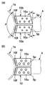
図1(a)、(b)において、円形鋼管柱1sの相対する両側面に、それぞれ、上部側の接合金物、下部側の接合金物を形成する左右一対の異形T形材10a、10bのフランジ10fが上下に所定の間隔をおいて、高力ボルト3により接合されており、H形断面梁4の上フランジ4aは上部側の接合金物の左右一対の異形T形材10aのウエブ10u下面に高力ボルト5で接合され、H形断面梁4の下フランジ4bは下部側の接合金物の左右一対の異形T形材10a、10bのウエブ10u上面に当接され高力ボルト5で接合されている。
【0014】
ここで用いた上部側の接合金物、下部側の接合金物を形成している左右一対の異形T形材10a、10bは、図2(a)、(b)に示すように、例えば、H形鋼6のフランジ6fとウエブ6uを幅方向に角度αで斜めに切断し、ウエブ6uを長さ方向に切断して得られるものであり、図3(a)、(b)に示すように、円形鋼管柱1sの曲面に当接するフランジを、ウエブ10u側端面に対して角度βで斜めに形成した傾斜フランジ10fにした異形T形材であり、フランジ10fに高力ボルト3を挿通するボルト孔3pを有し、ウエブ10uに高力ボルト5を挿通するボルト孔5pを有するものである。
このように形成された上部側の接合金物を形成する一対の異形T形材10a、10bは、図4(a)に示すように、平行に左右に並列配置して円形鋼管柱1sの曲面に当接した状態で、左右一対の異形T形材10a、10bの傾斜フランジ10f面が鈍角βのV字を形成し斜めに向き合うように配置するものである。このとき、左右一対の異形T形材10a、10bの傾斜フランジ10f面は、それぞれ円形鋼管柱1sの曲面と線接触し、その状態で鈍角βのV字を形成し斜めに向き合うように配置するものである。
【0015】
なお、ここでは、左右一対の異形T形材10a、10bのウエブ10uの端部形状は、左右に平行に並列配置した場合に傾斜フランジ10fと平行になる傾斜面を形成するようにしたが、図2(c)に示すように、ウエブ10u側端面に対して直角に形成した左右一対の異形T形材10を用いて図4(b)に示すように配置することができる。
図4(a)の場合において、一対の異形T形材10a、10bを円形鋼管柱1sに接合する高力ボルト3は、ここでは、円形鋼管柱1sとフランジ10f面との当接部において、フランジ10面と直角方向から円形鋼管柱1sの中心に向くようにボルト孔3pに、円形鋼管柱1sの内部側から円形鋼管柱1sの中心を向くように形成されたボルト孔3pから挿通され、円形鋼管柱1sの外部側に当接された一対の異形T形材10a、10bの傾斜フランジ10fのボルト孔3pを経て外部に突出させ、ナットを螺合・締結して、円形鋼管柱1sと一対の異形T形材10a、10bの傾斜フランジ10fを締結するものである。
高力ボルト3を箱形断面柱1の内部からボルト孔3pに挿入する際には、例えば、本出願人の出願になる、特開2000−213070号公報に記載されるような、ボルト搬送装置と引出治具などを用いることができる。
【0016】
下部側の接合金物を形成する左右一対の異形T形材10a、10bも同様にして、円形鋼管柱1sに高力ボルト3により接合されるので、説明を省略する。
このようにして、左右一対の異形T形材10a、10bからなる上部側の接合金物と下部側の接合金物を円形鋼管柱1sの上下に高力ボルト3により接合してから、上部側の接合金物を形成する左右一対の異形T形材10a、10bのウエブ10fの下面にH形断面梁4の上フランジ4aの上面を当接し、下部側の接合金物を形成する左右一対の異形T形材10a、10bのウエブ10fの上面にH形断面梁4の下フランジ4aの下面を当接して、高力ボルト5により接合することにより、図1に示すような、円形鋼管柱1sとH形断面梁4の接合構造を得ることができる。
この実施例1では、高力ボルト3を、この当接部において円形鋼管柱1の中心を向くように挿通して締結するので、曲面と平面の当接であっても安定した締結ができ、この接合部における圧縮力と引張力に対する接合部性能(剛性、耐力)を向上させることができる。
【0017】
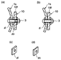
なお、座金を図示しなかったが、通常、座金を使用するものであり、その場合、特に、円形鋼管柱1sの曲面と異形T形材10a、10bの傾斜フランジ10fとの間に介挿する座金zの場合には、例えば図5(a)に示すように、円形鋼管柱1sの外部側で、円形鋼管柱1sの曲面に合う曲面に形成した当接面と異形T形材10a、10bの傾斜フランジ10fに当接する平坦な当接面を有する図5(d)に示すような座金zoを用いて、円形鋼管柱1sの曲面と異形T形材10a、10bの傾斜フランジ10fとの間の接触をより安定させ接合部性能(剛性、耐力)をさらに向上させることができる。特に、円形鋼管柱と異形T形材または異形L形材のフランジ間に座金を介挿した場合には、異形T形材または異形L形材のフランジの先端部と円形鋼管柱の接触およびそれに起因するてこ反力がなくなりボルトの負荷を低減させるメリッともある。
図5(b)のように、円形鋼管柱1sの外部側で、円形鋼管柱1s曲面に異形T形材10a、10bの傾斜フランジ10fを直接当接する場合もあり、この場合には、座金zoの使用する必要はなくなる。また、円形鋼管柱1sの内部側で、円形鋼管柱1sの曲面と高力ボルト3の頭部との間に介挿する座金の場合には、例えば円形鋼管柱1sの曲面に合う曲面に形成した当接面と高力ボルト3に当接する平坦な当接面を有する図5(c)に示すような座金ziを用いて、円形鋼管柱1sの曲面と高力ボルト3の間の接触をより安定させ接合部性能(剛性、耐力)をさらに向上させることができる。なお、座金形状については、図5(c)、(d)の座金zi、zoの場合は角形であるが、円形であってもよい。
【0018】
この実施例1においては、上部側の接合金物、下部側の接合金物を、それぞれ上側の左右一対の異形T形材10a、10bおよび向きを反対にした下側の左右一対の異形T形材10c、10dにより形成して、基本的には、その傾斜フランジ12fを円形鋼管柱1sの曲面に、鈍角βのV字を形成し斜めに向き合うように配置することにより、円形鋼管柱1sの曲面を傾斜フランジ10fを挟み込むように当接して2線の線接触による当接部を形成できるので、安定した当接ができ、接合部性能(剛性、耐力)を向上させることができる。
上部側の接合金物、下部側の接合金物を形成する左右一対の異形T形材10aと10bに対するH形断面梁4の取り付けは、上部側の接合金物、下部側の接合金物を円形鋼管柱1sに接合した後に行うことができるが、円形鋼管柱1sに対する上部側および下部側の接合金物を形成する左右一対の異形T形材10aと10bの接合と、H形断面梁4との接合を並行して行うなど、施工性を高められるように接合手順を考慮することが好ましい。例えば、H形断面梁4を上部側の接合金物、下部側の接合金物に予め接合してから、上部側の接合金物、下部側の接合金物を箱形断面柱1sに接合することなども考慮する。
【0019】
[実施例2]
以下に本発明の実施例2について、図6〜図9に基づいて説明する。
この実施例2は、上部側の接合金物を形成する上側の左右一対の異形L形材12aと12b、この上側の左右一対の異形L形材12aと12bの下側に向きを反対にして配置された下側の左右一対の異形L形材12cと12dと、下部側の接合金物を形成する上側の左右一対の異形L形材12aと12b、この上側の左右一対の異形L形材12aと12bの下側に向きを反対にして配置された下側の左右一対の異形L形材12cと12dと、高力ボルト3、5を用いた円形鋼管柱1sとH形断面梁4の接合構造において適用した場合のものである。基本的には、接合金物を異形L形材で形成する点で、接合金物を異形T形材で形成する実施例1とは異なるものである。実施例1と共通部分については、説明を省略する。H形断面梁4は、通常の場合、円形鋼管柱1sの側面に1〜4本取り付けられるが、ここでは、円形鋼管柱1sの相対する両側面に、上下に所定間隔をおいて高力ボルト3により接合された上部側の接合金物と下部側の接合金物間に高力ボルト5によりH形断面梁4を取り付けの場合について代表説明する。
【0020】
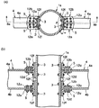
図6(a)、(b)において、円形鋼管柱1sの相対する両側面に、それぞれ、上部側の接合金物を形成する左右一対の異形L形材12aと12b、この上側の左右一対の異形L形材12aと12bの下側に向きを反対にして配置された下側の左右一対の異形L形材12cと12dと、下部側の接合金物を形成する上側の左右一対の異形L形材12aと12b、この上側の左右一対の異形L形材12aと12bの下側に向きを反対にして配置された下側の左右一対の異形L形材12cと12dの傾斜フランジ12fが、それぞれ、高力ボルト3により接合されている。
H形断面梁4の上フランジ4aは、上部側の接合金物を形成する上側の左右一対の異形L形材12aのウエブ12uの下面と下側の左右一対の異形L形材12cと12dのウエブ12uの上面間に当接され、高力ボルト5により接合されており、H形断面梁4の下フランジ4aは、下部側の接合金物の上側の左右一対の異形L形材12aと12bのウエブ2uの下面と下側の左右一対の異形L形材12cと12dのウエブ2uの上面間に当接され高力ボルト5により接合されている。
【0021】
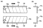
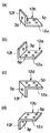
ここで用いた上部側の接合金物、下部側の接合金物を形成している上側の左右一対の異形L形材12aと12b、下側の左右一対の異形L形材12cと12dは、図7(a)、(b)に示すように、例えば、不等辺山形鋼131、132のフランジ13fとウエブ13uを幅方向に角度αで斜めに切断して得られるものであり、図8(a)、(b)に示すように、円形鋼管柱1sの曲面に当接するフランジ12fを、ウエブ12u側端面に対して角度αで斜めに形成して傾斜フランジ12fにした異形L形材であり、フランジ12fに高力ボルト3を挿通するボルト孔3pを有し、ウエブ12uに高力ボルト5を挿通するボルト孔5pを有するものである。ここで用いた各異形L形材では、その端面が傾斜フランジと平行に形成しているが、図4(b)に示すように、側端面と直角に形成してもよい。
【0022】
このように形成された上部側の接合金物を形成する上側の左右一対の異形L形材12aと12bは、図9に示すように、平行に左右に並列配置して円形鋼管柱1sの曲面に当接した状態で、左右一対の異形L形材2a、2bの傾斜フランジ2f面が鈍角βのV字を形成し斜めに向き合うように配置するものである。このとき、左右一対の異形L形材12aと12bの傾斜フランジ12f面は、それぞれ円形鋼管柱1sの曲面と線接触し、その状態で鈍角βのV字を形成し斜めに向き合うように配置するものである。
また、上部側の接合金物を形成する下側の左右一対の異形T形材12cと12dは、図8(c)、図8(d)に示すように、上側の左右一対の異形L形材12aと12bと向きを反対にして、平行に左右に並列配置して円形鋼管柱1sの曲面に当接した状態で、左右一対の異形T形材12cと12dの傾斜フランジ12f面が鈍角βのV字を形成し斜めに向き合うように配置するものである。このとき、左右一対の異形L形材12cと12dの傾斜フランジ12f面は、それぞれ円形鋼管柱1sの曲面と線接触し、その状態で鈍角βのV字を形成し斜めに向き合うように配置するものである。
【0023】
下部側の接合金物を形成する上側の左右一対の異形L形材12aと12b、下側の左右一対の異形L形材12cと12dも、上部側の接合金物を形成する上側の左右一対の異形L形材12aと12b、下側の左右一対の異形L形材12cと12d同様に形成し配置する。
この上部側および下部側の接合金物を形成する上側の左右一対の異形L形材12aと12b、下側の左右一対の異形L形材12cと12dを円形鋼管柱1sに接合する高力ボルト3は、ここでは、円形鋼管柱1sと傾斜フランジ12f面との当接部において、円形鋼管柱1sの内部側から円形鋼管柱1sの中心を向くように形成されたボルト孔3pに挿通し、円形鋼管柱1sの外部側に当接された一対の異形L形材12aと12b、12cと12dの傾斜フランジ12fのボルト孔3pを経て外部に突出させ、ナットを螺合・締結して、円形鋼管柱1sと上側の左右一対の異形L形材12aと12b、下側の左右一対の異形L形材12cと12dの傾斜フランジ12fを締結するものである。
H形断面梁4の上フランジ4aは、上部側の接合金物を形成する上側の左右一対の異形T形材2aと2bのウエブ12fの下面と、下側の左右一対の異形T形材12cと12dのウエブ12fの上面間に高力ボルト5により接合され、また、H形断面梁4の下フランジ4bは、下部側の接合金物を形成する上側の左右一対の異形T形材2aと2bのウエブ12fの下面と、下側の左右一対の異形T形材12cと12dのウエブ12fの上面間に高力ボルト5により接合され、図5に示すような、円形鋼管柱1sとH形断面梁4の接合構造を得ることができる。
【0024】
なお、この実施例2では、座金を図示しなかったが、実施例1で記載の通りであるので、説明は省略する。
上部側の接合金物、下部側の接合金物を形成する上側の左右一対の異形L形材12aと12b、下側の左右一対の異形L形材12cと12dに対するH形断面梁4の取り付けは、上側接合金物、下側接合金物を円形鋼管柱1sに接合した後に行うことができるが、円形鋼管柱1sに対する上部側および下部側の接合金物を形成する上側の左右一対の異形L形材12aと12b、下側の左右一対の異形L形材12cと12dの接合と、H形断面梁4との接合を並行して行うなど、施工性を高められるように接合手順を考慮することが好ましい。例えば、H形断面梁4を上側接合金物、下側接合金物に予め接合してから、上側接合金物、下側接合金物を箱形断面柱1sに接合することなども考慮する。
【0025】
この実施例2においては、上部側の接合金物、下部側の接合金物を、それぞれ上側の左右一対の異形L形材12a、12bおよび向きを反対にした下側の左右一対の異形L形材12c、12dにより形成して、基本的には、その傾斜フランジ12fを円形鋼管柱1sの曲面に、鈍角βのV字を形成し斜めに向き合うように配置することにより、円形鋼管柱1sの曲面を傾斜フランジ12f挟み込むように当接して2線の線接触による当接部を形成できるので、実施例1と同様、安定した当接ができ、接合部性能(剛性、耐力)を向上させることができる。
【0026】
本発明は、上記の実施例の内容に限定されるものではない。例えばH形断面梁の取り付け本数、異形T形材および異形L形材の形状、ボルト孔配置(含む数)、座金の使用の有無、座金の使用部位、座金形状、円形鋼管柱内部からの高力ボルトの挿入手段、接合部の施工手順などについては、接合対象物、接合部配置、要求される接合部性能などに応じて、上記請求項を満足する範囲内で変更のあるものである。
【0027】
【発明の効果】
本発明では、円形鋼管柱とH形断面梁を接合金物と高力ボルトを用いて高力ボルト接合する場合において、接合金物を、平行に並列配置した左右一対の傾斜フランジを有する異形T形材または異形L形材で形成しているので、円形鋼管柱の曲面に対して安定的に当接(2線の線接触)することができ、高力ボルトによる接合部性能(剛性、耐力)を十分に確保可能な、円形鋼管柱とH形断面梁の接合構造を容易に実現させることができる。
本発明の接合金物は、例えば強度特性の良好なH形鋼や山形鋼を斜め切断して容易に得られるものであり、従来の鋳物製作や曲げ・溶接加工によるもの、あるいは通常のT形材(スプリットティ)やL形材(アングル材)と特殊金物との併用によるものなどを使用する場合に比較して安価に得られ施工性も良好である。また、傾斜フランジの傾斜角により円形鋼管柱の曲面のRによるサイズバリエーション対応が容易である。
【図面の簡単な説明】
【図1】(a)図は、本発明の実施例1による円形鋼管柱とH形断面梁の高力ボルト接合構造例で、高力ボルト接合が完了した状態を示す平面断面説明図、(b)図は、(a)図のAa−Ab矢視断面説明図。
【図2】(a)図は、実施例1で接合金物を形成する左右一対の異形T形材の製作例を示す平面説明図、(b)図は、(a)図の側面説明図、(c)図は異形T形材の他の例を示す平面説明図。
【図3】(a)図は、実施例1で接合金物を形成する左右一対の一方の異形T形材例を示す立体説明図、(b)図は、実施例1で接合金物を形成する左右一対の他方の異形T形材例を示す立体説明図。
【図4】実施例1で接合金物を形成する左右一対の一方の異形T形材の配置例を示す平面説明図。
【図5】実施例1での円形鋼管柱の曲面に当接する座金の使用状態を示す断面説明図で、(a)図は、円形鋼管柱の内部側と外部側の曲面に特殊座金を使用した場合を示し、(b)図は、円形鋼管柱の内部側に特殊座金を使用した場合を示す。
【図6】(a)図は、本発明の実施例2による円形鋼管柱とH形断面梁の高力ボルト接合構造例で、高力ボルト接合が完了した状態を示す平面断面説明図、(b)図は、(a)図のBa−Bb矢視断面説明図。
【図7】(a)図は、実施例2で接合金物を形成する左右一対の異形L形材の製作例を示す平面説明図、(b)図は、(a)図の側面説明図。
【図8】(a)図は、実施例2で上部側の接合金物を形成する上側の左右一対の一方の異形L形材例を示す立体説明図、(b)図は、実施例2で上部側の接合金物を形成する他方の左右一対の他方の異形L形材例を示す立体説明図、(c)図は、実施例2で上部側の接合金物を形成する下側の左右一対の一方の異形L形材例を示す立体説明図、(b)図は、実施例2で上部側の接合金物を形成する下側の左右一対の他方の異形L形材例を示す立体説明図。
【図9】実施例2で接合金物を形成する左右一対の一方の異形L形材の配置例を示す平面説明図。
【図10】(a)図は、従来のスプリットティと高力ボルトを用いた角形鋼管柱とH形鋼梁の高力ボルト接合構造例を示す立体説明図、(b)図は、(a)図のスプリットティと高力ボルトを用いた角形鋼管柱とH形鋼梁の高力ボルト接合構造例を示す平面断面説明図、(c)図は、(a)図のCa−Cb矢視断面説明図。
【図11】従来の他のアングル材と高力ボルトを用いた角形鋼管柱とH形鋼梁の高力ボルト接合構造例を示す平面断面説明図、(b)図は、(a)図のDa−Db矢視断面説明図。
【図12】従来のスプリットティと高力ボルトを用いた円形鋼管柱とH形鋼梁の高力ボルト接合構造例を示す平面断面説明図。
【図13】従来の鋳物製作または曲げ加工・溶接加工による接合金物と高力ボルトを用いた円形鋼管柱とH形鋼梁の高力ボルト接合構造例を示す平面説明図。
【図14】従来のスプリットティと特殊金物を併用して用い高力ボルトを用いた円形鋼管柱とH形鋼梁の高力ボルト接合構造例を示す平面断面説明図。
【符号の説明】
1 角形鋼管柱(角形箱形断面柱)
1s 円形鋼管柱(円形鋼管柱)
2a 上側スプリットティ 2b 下側スプリットティ
2f 垂直板(フランジ) 2u 水平板(ウエブ)
3 高力ボルト、ワンサイドボルト 3p ボルト孔
4 H形鋼梁(H形断面梁) 4a 上フランジ
4b 下フランジ 5 高力ボルト
6 H形鋼 6f フランジ
6u ウエブ 7a、7b アングル材
7f 垂直板(フランジ) 7u 水平板(ウエブ)
8 接合金物 8f 垂直板(フランジ)
8u 水平板(ウエブ) 9a、9b 特殊金物
10、10a、10b 異形T形材
10f 垂直板(フランジ) 10u 水平板(ウエブ)
12a 異形L形材 12f 垂直板(フランジ)
12u 水平板(ウエブ) 131、132 不等辺山形鋼
13f フランジ 13u ウエブ
zo 座金(外部側) zi 座金(内部側)[0001]
TECHNICAL FIELD OF THE INVENTION
The present invention mainly relates to the height of a circular steel pipe column and an H-shaped beam in which an H-shaped cross-section beam is joined to a circular steel pipe column constituting a steel structure building by high-strength bolts via a joint metal such as split tee or angle material. The present invention relates to a force bolt joining structure and a joining hardware.
[0002]
[Prior art]
Conventionally, for example, in a column-beam joint type for a square steel tubular column and an H-shaped steel beam, FIGS. 10A, 10B, and 10C are disclosed in, for example, JP-A-11-269986. As described above, a high-strength bolted joint structure of a rectangular steel tube column 1 and an H-shaped steel beam 4 using a pair of upper and lower split tees 2a and 2b and high-strength bolts 3 and 5 is known.
In this joint structure, the flange 2f of a pair of upper and lower split tees 2a and 2b is joined to each side of the square steel tubular column 1 with high-strength bolts 3, respectively, and the web 2u of the upper and lower split tees 2a and 2b is , The upper surface of the upper flange 4a of the H-shaped steel beam 4 on the lower surface side of the horizontal plate 2p of the upper split tee 2a, and the upper surface side of the web 2u of the lower split tee 2b. In general, a high-strength bolted joint structure of a rectangular steel pipe column and an H-shaped steel beam, which reduces the welding load, is formed by joining the upper surface of the lower flange 4b of the H-shaped steel beam 4 to the upper surface thereof and joining with a high-strength bolt 5. I have. The split tees 2a and 2b used here are those obtained by cutting an H-section steel in the length direction with its web in a T-section, those obtained by welding and assembling a plate into a T-shape, or castings. Are known.
As shown in FIGS. 11A and 11B, instead of the split tees 2a and 2b, a pair of upper and lower angle members 7a and 7b, and a pair of lower and upper angle members 7c and 7d are combined with a high strength. A high-strength bolted joint structure between the square steel pipe column 1 and the H-beam 4 using the bolts 3 and 5 is also known.
In this joint structure, a pair of upper and lower angle members 7a and 7b and a pair of lower and upper pair of angle members 7c and 7d, which are arranged in opposite directions, are mounted on the side of the rectangular steel tube column 1 by a high flange, respectively. The H-shaped steel beam 4 is joined to the upper flange 4a of the H-shaped steel beam 4 by a pair of upper and lower angle members 7a and 7b so as to sandwich the web 7u from above and below, and joined by a high-strength bolt 5, The lower flange 4b of the steel beam 4 is in contact with the lower pair of upper and lower angle members 7c and 7d so as to sandwich the flange 2f from above and below and is joined by the high-strength bolt 5. As the angle members 7a and 7b, 7c and 7d used here, L-shaped members obtained by cutting a trapezoidal angle steel in the width direction are known.
[0003]
On the other hand, as shown in FIG. 12, a high-strength bolt joint structure of a circular steel pipe column 1s and an H-shaped steel beam 4 using a pair of upper and lower split tees 2a and 2b and high-strength bolts 3 and 5 is known. In this joint structure, when the upper and lower split tees 2a and 2b as shown in FIG. 10 are used, the flat flange 2f surface of the split tee comes into contact with the curved circular steel pipe column 1s, so that one line contact is made. Therefore, there is a problem in securing the adhesion, and sufficient joint performance cannot be obtained even by joining with the high-strength bolts 3.
(1) As shown in FIG. 13, a deformed T-shaped member formed by casting or having a curved flange 8f and a web 8u fitted to the curved surface of the circular steel tubular column 1s or formed by bending and welding. Material 8 is used.
(2) As shown in FIG. 14, in order to secure adhesion between the T-shaped cross-section split tee 2a (2b) used for the rectangular steel pipe column 1 as shown in FIG. 10 and the circular steel pipe column 1s. The specially shaped hardware 9a, 9b having a curved surface that fits the curved surface of the circular steel pipe column 1s is used.
Proposals such as have been made.
However, in the case of casting (1), a special material is used, so there is a limitation in strength, and since it is not a plane contact like a square steel pipe, a size variation by a round steel pipe R is required. There is also a problem that the cost is high.
In addition, the method of (1) by bending and welding requires bending and welding of a plate, and has a problem that the processing load is large and the cost is high. In the case of (2), a split tee having a T-shaped cross section and a metal having a special shape must be used in combination.
[0004]
[Problems to be solved by the invention]
INDUSTRIAL APPLICABILITY The present invention stably secures joint performance (rigidity, proof strength) in a high-strength bolted joint structure of a circular steel pipe column and an H-shaped steel beam using a joint metal member such as a T-shaped joint metal member or an L-shaped joint metal member and a high-strength bolt. An object of the present invention is to provide a high-strength bolted joint structure between a circular steel pipe column and an H-shaped cross-section beam using a specially shaped joint metal member capable of reducing the cost burden, and a joint metal member used in this joint structure.
[0005]
[Means for Solving the Problems]
The present invention has the following aspects (1) to (7) to achieve the above object.
(1). High-strength bolted joints between circular steel tubular columns and H-shaped beams using T-shaped joints and high-strength bolts with a vertical plate (flange) joined to a circular steel tubular column and a horizontal plate (web) joined to an H-shaped beam In the structure, a T-shaped joint hardware for joining at predetermined intervals above and below a circular steel pipe column is formed of a pair of right and left irregularly shaped T-shaped members having inclined flanges arranged in parallel with an H-shaped cross-section beam. The flanges of the deformed T-shaped members are respectively in contact with the circular steel pipe columns, and a pair of the circular steel pipe columns and the pair of high-strength bolts are inserted through the contact portions or in the vicinity of the contact portions so as to face the center of the circular steel pipe columns. A circular steel pipe column, characterized in that flanges of a deformed T-shaped member are fastened and joined, and upper and lower flanges of an H-shaped cross-section beam are each connected to a pair of right and left deformed T-shaped webs with high-strength bolts. High strength bolted joints of H-section beams .
(2). High-strength bolted joint of circular steel tubular column and H-shaped beam using L-shaped joint hardware and high-strength bolt having vertical plate (flange) joined with circular steel tube column and horizontal plate (web) joined with H-shaped beam In the structure, a pair of left and right deformed L-shaped members having inclined flanges arranged in parallel with the H-shaped cross-section beams are formed with L-shaped metal fittings to be joined at predetermined intervals above and below the circular steel pipe column. A pair of left and right deformed L-shaped members are arranged in a pair with the upper and lower flanges of the H-shaped cross-section beam so that the directions are opposite to each other so that the web comes into contact with the upper and lower flanges. The circular steel pipe column and the flange of the deformed L-shaped material are fastened and joined by a high-strength bolt inserted into the column or in the vicinity of the contact portion so as to face the center of the circular steel pipe column. The upper and lower flanges of the beam Pair, high-strength bolted connection structure of the circular tubular columns H-shaped cross-section beam, characterized in that so as to web to high-strength bolted connection of the pair of upper and lower profile L profile.
(3). In (1), the flange surface on the side of the pair of right and left deformed T-shaped members arranged in parallel that is in contact with the circular steel pipe column is formed to be a surface perpendicular to the direction in which the high-strength bolt is inserted. High-strength bolted joint structure of circular steel pipe columns and H-shaped beams.
(4). In (2), the pair of left and right deformed L-shaped members having a pair of deformed L-shaped members whose flange surfaces on the side abutting against the circular steel pipe columns are formed to be surfaces perpendicular to the direction in which the high-strength bolts are inserted. High-strength bolted joint structure of circular steel pipe columns and H-shaped beams.
(5). (1) In any one of (1) to (4), the circular steel pipe column and the H-shape are characterized in that the washer contacting the curved surface side of the circular steel pipe column has a seat surface formed into a curved surface that matches the curved surface of the circular steel pipe column. High-strength bolted structure for cross-section beams.
(6). This is a deformed T-shaped member in which the H-shaped section is cut obliquely in the width direction, the web is cut in parallel to the flange surface, and the flange surface in contact with the circular steel pipe column is formed obliquely to the end surface on the web side. When the deformed T-shaped members are arranged side by side in parallel in parallel, the flange surfaces of the pair of right and left deformed T-shaped members are arranged so as to form an obtuse V-shape. Deformed T-section for forming.
(7). It is a deformed L-shaped material in which the angled section is cut diagonally in the width direction and the flange surface in contact with the circular steel pipe column is formed obliquely to the end face on the web side. A deformed L-shaped member for forming an L-shaped joint hardware, wherein the pair of left and right deformed T-shaped members is disposed such that the flange surfaces of the pair of right and left deformed T-shaped members form an obtuse V-shape.
[0006]
BEST MODE FOR CARRYING OUT THE INVENTION
The present invention relates to a method for forming a circular steel pipe column such as a circular steel pipe column and an H-shaped beam such as an H-beam using an L-shaped joint metal such as a split tee or an L-shaped joint metal such as an angle member and a tensile high-strength bolt. It is applied in a high strength bolt joint structure.
In the high-strength bolted joint structure of the circular steel pipe column and the H-shaped section beam according to the present invention, basically, a T-shaped metal joint is used as a metal joint to be vertically joined to the circular steel pipe column, and an L-shaped metal joint is used. May be used.
[0007]
When a T-shaped joint is used, the T-shaped joint is formed of a pair of right and left deformed T-shaped members having flat inclined flange surfaces arranged in parallel with the H-shaped cross-section beams. The flange surface of the section is brought into contact with the circular steel pipe column, and the circular steel pipe column and a pair of irregularly shaped T-shaped sections are formed with a high-strength bolt inserted in the contact portion or in the vicinity of the contact portion so as to face the center of the circular steel pipe column. The flanges are fastened and joined, and the upper and lower flanges of the H-shaped cross-section beam are joined by high-strength bolts to a pair of right and left deformed T-shaped webs, respectively. When an L-shaped joint is used, the L-shaped joint is formed of a pair of left and right and upper and lower pairs of deformed L-shaped members, and comes into contact with the upper and lower flanges of the H-section beam from above and below. So that the flanges abut on the top and bottom of the circular steel pipe column, and are inserted so as to face the center of the circular steel pipe column in this contact part or in the area near the contact part. The high-strength bolts are connected and fastened to a circular steel pipe column, and the upper and lower flanges of the H-shaped cross-section beam are joined by high-strength bolts between a pair of left and right and upper and lower pairs of deformed L-shaped members, respectively. It is.
[0008]
In the present invention, basically, a pair of small-width irregularly shaped T-shaped or L-shaped members having a flat inclined flange surface, which are different from the conventional jointed metal, are arranged side by side on the left and right. The inclined flange surfaces of a pair of deformed T-shaped members or deformed L-shaped members are arranged so that the inclined flange surfaces of a pair of deformed T-shaped members or deformed L-shaped members face each other so as to form a V-shape. Is abutted against the circular steel pipe column by line contact, high-strength bolted in this abutting portion or in the vicinity of the abutting portion, and stabilizing the connection with the circular steel pipe column in a state where the H-shaped cross-section beam is joined with the high-strength bolt, This ensures stable joining performance and reduces the cost burden.
The deformed T-shaped material or the deformed L-shaped material forming the joint metal used in the present invention is based on the premise that a flat flange surface is brought into contact with a curved surface of a circular box-shaped cross section. Or, when the deformed L-shaped member is formed by using the same width as the conventionally known T-shaped or L-shaped jointed metal and used alone, the same as when using the conventionally known T-shaped or L-shaped jointed metal, The contact between the flange surface and the curved surface of the circular box-shaped cross section becomes a straight line contact, and stable joining is difficult.
Therefore, in the present invention, the width of the deformed T-shaped material or the deformed L-shaped material is reduced to about half of the width of the conventional jointed metal, and the flange abutting on the circular section column is formed obliquely. When the flange of the material abuts against the circular column, the pair of right and left deformed T-shaped members are arranged so that the flange surfaces of the pair of right and left deformed T-shaped members form an obtuse V-shape and face each other. A high-strength bolt joint is made between the flange of the profile and the contact portion with the circular column. At this time, the high-strength bolt is inserted so as to face the center of the circular steel pipe column in order to stabilize the joining, and the flange surfaces of the pair of right and left deformed T-shaped members or deformed L-shaped members are inserted through the high-strength bolt. It is preferable to set the inclination angle of the flange so as to form a plane perpendicular to the direction.
[0009]
When joining a flange of a deformed T-shaped member or a deformed L-shaped member to the curved surface of a circular steel tube column, the curved surface of the circular steel tube column and the deformed T-shaped member or deformed L-shaped member are inserted in units of one high-strength bolt. It is also possible to consider securing the contact state stably by inserting a washer having a curved surface that matches the curved surface of the circular steel pipe column between the flanges of the material. In addition, on the inner side of the circular steel pipe column, between the curved surface of the circular steel pipe column and the head or nut of the bolt, a washer formed into a curved surface that matches the curved surface of the circular steel pipe column in units of one high-strength bolt insertion portion. It can also be considered that the contact state is stably ensured by interposing.
Basically, the shape of these washers is the surface opposite to the contact surface with the circular steel pipe column, that is, the contact surface with the flange surface of the deformed T-shaped or L-shaped material, the head of the bolt and the nut. Is preferably formed as a flat surface.
By doing so, the flange surfaces of the pair of left and right deformed T-shaped members or deformed L-shaped members and the circular steel pipe column can be brought into surface contact with the high-strength bolt insertion unit via washers, and stable joint performance is achieved. Can be demonstrated. In particular, when a washer is inserted between the circular steel pipe column and the flange of the deformed T-shaped or L-shaped material, the contact between the tip of the flange of the deformed T-shaped or L-shaped material and the circular steel pipe column and the There is also a merit of eliminating the lever reaction force caused and reducing the load on the bolt.
The deformed T-shaped material used in the present invention can be easily obtained, for example, by cutting an H-shaped steel obliquely in the width direction and cutting the center of the web in parallel with the flange surface. By selecting the H-section steel of a predetermined size in consideration of the size of the cross-sectional column, and setting the width of the deformed T-section and the inclination angle of the flange when obliquely cutting, the size of the circular steel pipe column, the H-section It is possible to easily obtain a deformed T-shaped member corresponding to the size of the column.
[0010]
Further, the deformed L-shaped member used in the present invention can be easily obtained by, for example, obliquely cutting a trapezoidal angle steel in the width direction, and taking into account the size of the circular steel pipe column and the size of the H-shaped section column. By selecting the unequal side angle steel of the size and setting the width of the deformed L-shaped material and the inclination angle of the flange when obliquely cutting, the deformed shape according to the size of the circular steel pipe column and the size of the H-shaped section column An L-shaped member can be easily obtained.
Note that the width of the deformed T-shaped member or the deformed L-shaped member and the inclination angle of the flange differ depending on the size of the circular steel pipe column and the size of the H-shaped section beam. The width of the flange is equal to or more than の, and the inclination angle of the flange is about 0 to 45 degrees with respect to a right angle plane.
As described above, in a high-strength bolted joint structure between a circular steel pipe column and an H-shaped cross-section beam using a joint metal formed of a deformed T-shaped member or a deformed L-shaped member, the flange surface of the joint metal member and the curved surface of the circular steel tube column are surface-shaped. Without contact, stable joining is enabled, and sufficient joint performance (rigidity, proof stress) can be stably secured at low cost.
[0011]
As the high-strength bolt used in the present invention, a male screw part is inserted from the inside of a circular steel pipe column having an outer surface with which a flange of a metal fitting is abutted, and a male screw portion is projected from the outer surface of the flange of the metal fitting, and a nut is screwed and tightened. Use a normal high-strength bolt to fasten the nut on the outside to fasten the flange of the joint and the box-shaped column between the head on the inside of the circular steel pipe column and the nut on the outside of the joint. it can. It is more preferable that the high-strength bolt is provided with a torque introducing structure at the end of the external thread portion on the outer side, and is capable of tightening by introducing the torque.
As another high-strength bolt, a nut is fixed to the inside of the circular steel pipe column, and inserted from the outside of the flange of the joint metal fitting in contact with the outer surface of the circular steel pipe column to insert it inside the circular steel pipe column. A head-tightening high-strength bolt for fastening the flange of the joint hardware and the box-shaped column between the nut fixed to the side and the head on the outer surface side of the flange of the joint hardware can be used. It is more preferable that the head tightening high-strength bolt has a torque introducing structure on the head on the outer side and has a special washer, and can be tightened by introducing a torque using a dedicated fastener. . Alternatively, one-side bolts can be used.
[0012]
In the present invention, when a normal high-strength bolt is used, it is to be inserted into the bolt hole from the inside of the circular steel pipe column, but when the insertion position is out of reach or where people cannot enter. As a method of inserting a high-strength bolt from the inside of a box-shaped column, there is, for example, a method of using a bolt conveying device and a drawing jig described in JP-A-2000-213070.
In addition, when using a head-tightening high-strength bolt, the nut is placed (fixed) inside the circular steel pipe column, but if the placement position is out of reach or where people cannot enter. As a method of arranging (fixing) the nut on the inner side of the circular steel pipe column, for example, a method of fixing the nut to the inner side in the process of manufacturing the circular steel pipe column, or a method of transferring a bolt described in JP-A-2000-213070. There is a method using a drawing jig.
[0013]
【Example】
[Example 1]
Hereinafter, a first embodiment of the present invention will be described with reference to FIGS.
The first embodiment is a case in which the present invention is applied to a joint structure of a circular steel pipe column 1s and an H-shaped cross-section beam 4 using a joint hardware composed of a pair of right and left deformed T-shaped members 10a and 10b and high-strength bolts 3 and 5. is there.
In general, one to four H-shaped cross-section beams 4 are attached to the side surface of the circular steel pipe column 1 s. Here, a pair of right and left deformed T-shaped members 10 a and 10 b are provided on opposite side surfaces of the circular steel pipe column 1 s. A description will be given of a case in which the metal joints are vertically joined at predetermined intervals by high-strength bolts 3 and an H-shaped cross-section beam 4 is attached between the upper and lower joints.
1 (a) and 1 (b), flanges of a pair of right and left deformed T-shaped members 10a and 10b forming an upper joint metal part and a lower joint metal part on opposite side surfaces of a circular steel tubular column 1s, respectively. The upper flange 4a of the H-shaped cross-section beam 4 is attached to the lower surface of the web 10u of the pair of right and left deformed T-shaped members 10a of the upper joint metal at predetermined intervals vertically. The lower flange 4b of the H-shaped cross-section beam 4 abuts on the upper surface of the web 10u of the pair of left and right deformed T-shaped members 10a and 10b, and is joined by the high-strength bolt 5. I have.
[0014]
The pair of left and right deformed T-shaped members 10a and 10b forming the upper metal joint and the lower metal joint used here are, for example, H-shaped as shown in FIGS. 2 (a) and 2 (b). It is obtained by cutting the flange 6f of the steel 6 and the web 6u obliquely at an angle α in the width direction and cutting the web 6u in the length direction, as shown in FIGS. 3 (a) and 3 (b). It is a deformed T-shaped member in which a flange abutting on the curved surface of the circular steel pipe column 1s is an inclined flange 10f formed at an angle β with respect to the end face on the web 10u side, and a bolt hole for inserting the high-strength bolt 3 into the flange 10f. 3p, and a bolt hole 5p for inserting the high-strength bolt 5 into the web 10u.
As shown in FIG. 4 (a), the pair of deformed T-shaped members 10a and 10b forming the upper metal joint formed in this way are arranged in parallel on the left and right sides to form a curved surface of the circular steel tube column 1s. In the contact state, the inclined flanges 10f of the pair of right and left deformed T-shaped members 10a and 10b form a V-shape with an obtuse angle β and are disposed so as to face diagonally. At this time, the inclined flange 10f surfaces of the pair of right and left deformed T-shaped members 10a and 10b are in line contact with the curved surface of the circular steel tubular column 1s, respectively, and form a V-shape with an obtuse angle β in this state and are arranged so as to face diagonally. Things.
[0015]
Here, the end shape of the web 10u of the pair of right and left irregularly shaped T-shaped members 10a and 10b forms an inclined surface which is parallel to the inclined flange 10f when arranged in parallel to the left and right. As shown in FIG. 2C, a pair of right and left deformed T-shaped members 10 formed at right angles to the end face on the side of the web 10u can be arranged as shown in FIG. 4B.
In the case of FIG. 4A, the high-strength bolt 3 that joins the pair of deformed T-shaped members 10 a and 10 b to the circular steel pipe column 1 s is, here, at the contact portion between the circular steel pipe column 1 s and the flange 10 f surface. The bolt hole 3p is inserted through the bolt hole 3p so as to face the center of the circular steel pipe column 1s from a direction perpendicular to the surface of the flange 10 and from the inner side of the circular steel pipe column 1s toward the center of the circular steel pipe column 1s. The pair of deformed T-shaped members 10a, 10b abutting on the outer side of the circular steel pipe column 1s is projected to the outside through the bolt holes 3p of the inclined flanges 10f, and nuts are screwed and fastened to form the circular steel pipe column 1s. The inclined flange 10f of the pair of modified T-shaped members 10a and 10b is fastened.
When the high-strength bolt 3 is inserted into the bolt hole 3p from the inside of the box-shaped section pillar 1, for example, a bolt conveying device as described in Japanese Patent Application Laid-Open No. 2000-213070 filed by the present applicant. And a drawing jig can be used.
[0016]
Similarly, the pair of left and right deformed T-shaped members 10a and 10b forming the lower metal joint are joined to the circular steel pipe column 1s by the high-strength bolts 3, and therefore description thereof is omitted.
In this manner, the upper metal joint and the lower metal joint made of the pair of right and left deformed T-shaped members 10a and 10b are joined to the upper and lower portions of the circular steel pipe column 1s by the high-strength bolts 3 and then to the upper joint. A pair of right and left deformed T-shaped members, which make contact with the upper surface of the upper flange 4a of the H-shaped cross-section beam 4 against the lower surfaces of the webs 10f of the pair of left and right deformed T-shaped materials 10a and 10b to form a lower metal joint. The lower surface of the lower flange 4a of the H-shaped section beam 4 is brought into contact with the upper surface of the web 10f of 10a, 10b and joined by a high-strength bolt 5 to form a circular steel tube column 1s and an H-shaped section as shown in FIG. The joint structure of the beam 4 can be obtained.
In the first embodiment, since the high-strength bolt 3 is inserted and fastened so as to face the center of the circular steel tube column 1 at the abutting portion, stable fastening can be performed even when the curved surface and the flat surface abut. The joint performance (rigidity, proof stress) with respect to compressive and tensile forces at this joint can be improved.
[0017]
Although the washer is not shown, a washer is generally used. In this case, the washer is interposed between the curved surface of the circular steel tubular column 1s and the inclined flange 10f of the modified T-shaped members 10a and 10b. In the case of the washer z, for example, as shown in FIG. 5 (a), on the outer side of the circular steel pipe column 1s, a contact surface formed into a curved surface matching the curved surface of the circular steel pipe column 1s and the deformed T-shaped members 10a, 10b. Using a washer zo as shown in FIG. 5 (d) having a flat contact surface which comes into contact with the inclined flange 10f of FIG. 5, between the curved surface of the circular steel tubular column 1s and the inclined flange 10f of the modified T-shaped members 10a and 10b. And the joint performance (rigidity, proof stress) can be further improved. In particular, when a washer is inserted between the circular steel pipe column and the flange of the deformed T-shaped or L-shaped material, the contact between the tip of the flange of the deformed T-shaped or L-shaped material and the circular steel pipe column and the There is also a merit that the lever reaction force caused by this is eliminated and the load on the bolt is reduced.
As shown in FIG. 5B, the inclined flanges 10f of the modified T-shaped members 10a and 10b may directly contact the curved surface of the circular steel pipe column 1s on the outer side of the circular steel pipe column 1s. In this case, the washer zo is used. There is no need to use In the case of a washer inserted between the curved surface of the circular steel tube column 1s and the head of the high-strength bolt 3 inside the circular steel tube column 1s, for example, the washer is formed into a curved surface that matches the curved surface of the circular steel tube column 1s. The contact between the curved surface of the circular steel pipe column 1s and the high-strength bolt 3 is performed using a washer zi as shown in FIG. It is possible to further stabilize and further improve the joint performance (rigidity, proof stress). The washer shape is square in the case of the washers zi and zo shown in FIGS. 5C and 5D, but may be circular.
[0018]
In the first embodiment, the upper metal joint and the lower metal joint are respectively replaced by a pair of left and right deformed T-shaped members 10a and 10b on the upper side and a pair of right and left deformed T-shaped members 10c in opposite directions. , 10d, and basically, by forming the inclined flange 12f on the curved surface of the circular steel pipe column 1s so as to form a V-shaped obtuse angle β and to face diagonally, the curved surface of the circular steel pipe column 1s is formed. Since the abutting portion can be formed by two-line contact by abutting the inclined flange 10f so as to sandwich the inclined flange 10f, stable abutment can be performed and the joint performance (rigidity, proof strength) can be improved.
Attachment of the H-shaped cross-section beam 4 to the pair of right and left deformed T-shaped members 10a and 10b forming the upper joint metal part and the lower joint metal part is performed by connecting the upper joint metal part and the lower joint metal part to a circular steel tube column 1s. The joining of the pair of left and right deformed T-shaped members 10a and 10b forming the upper and lower joining hardware for the circular steel tubular column 1s and the joining with the H-shaped cross-section beam 4 are performed in parallel. It is preferable to consider the joining procedure so that the workability can be enhanced. For example, it is also possible to consider joining the H-shaped section beam 4 to the upper joint piece and the lower joint piece in advance, and then joining the upper joint piece and the lower joint piece to the box-shaped section column 1s. I do.
[0019]
[Example 2]
Hereinafter, a second embodiment of the present invention will be described with reference to FIGS.
In the second embodiment, a pair of upper left and right deformed L-shaped members 12a and 12b forming an upper metal joint, and a pair of left and right upper left and right deformed L-shaped materials 12a and 12b are arranged in opposite directions below. A pair of left and right deformed L-shaped members 12c and 12d, a pair of upper left and right deformed L-shaped members 12a and 12b forming a lower metal joint, and a pair of upper left and right deformed L-shaped members 12a are formed. A joint structure of a pair of left and right deformed L-shaped members 12c and 12d arranged on the lower side of the lower side of 12b in opposite directions, and a circular steel pipe column 1s and an H-shaped beam 4 using high-strength bolts 3 and 5 This is the case when applied in. Basically, it differs from the first embodiment in which the metal joint is formed of a modified T-shaped material in that the metal joint is formed of a modified L-shaped material. Description of the same parts as in the first embodiment will be omitted. In general, one to four H-shaped cross-section beams 4 are attached to the side surface of the circular steel tube column 1s, but here, high-strength bolts are provided on opposite side surfaces of the circular steel tube column 1s at predetermined intervals vertically. A case in which the H-shaped cross-section beam 4 is attached between the upper metal joint and the lower metal joint joined by the high-strength bolt 5 will be described.
[0020]
6 (a) and 6 (b), a pair of left and right deformed L-shaped members 12a and 12b forming an upper metal joint are respectively formed on opposite side surfaces of the circular steel tubular column 1s, and a pair of left and right deformed shapes on the upper side. A pair of lower left and right deformed L-shaped members 12c and 12d arranged on the lower side of the L-shaped members 12a and 12b in opposite directions, and a pair of upper left and right deformed L-shaped members forming a lower metal joint 12a and 12b, a pair of lower left and right deformed L-shaped members 12c and 12d, which are arranged on the lower side of the upper left and right pair of deformed L-shaped members 12a and 12b in opposite directions, respectively, are inclined flanges 12f, They are joined by high strength bolts 3.
The upper flange 4a of the H-shaped cross-section beam 4 is formed by a lower surface of a pair of left and right deformed L-shaped members 12a and a pair of lower left and right pair of deformed L-shaped members 12c and 12d which form an upper joint metal part. The lower flange 4a of the H-shaped cross-section beam 4 is a web of a pair of left and right deformed L-shaped members 12a and 12b on the upper side of the lower metal fitting. The lower surface of 2u and the upper surface of the pair of left and right deformed L-shaped members 12c and 12d on the lower side are in contact with each other and are joined by high-strength bolts 5.
[0021]
The upper right and left pair of deformed L-shaped members 12a and 12b and the lower left and right pair of deformed L-shaped members 12c and 12d forming the upper and lower metal joints used in FIG. As shown in (a) and (b), for example, 1 , 13 2 8a is obtained by obliquely cutting the flange 13f and the web 13u at an angle α in the width direction, and as shown in FIGS. 8 (a) and 8 (b), the flange 12f abutting on the curved surface of the circular steel pipe column 1s is provided. Is an oblong flange 12f formed obliquely at an angle α with respect to the end face on the side of the web 12u, having a bolt hole 3p through which the high-strength bolt 3 is inserted in the flange 12f. It has a bolt hole 5p through which the bolt 5 is inserted. In each of the modified L-shaped members used here, the end face is formed parallel to the inclined flange, but may be formed at right angles to the side end face as shown in FIG.
[0022]
As shown in FIG. 9, the upper left and right pair of deformed L-shaped members 12a and 12b forming the upper metal joint formed in this way are arranged side by side in parallel and on the curved surface of the circular steel tube column 1s. In the contact state, the inclined flanges 2f of the pair of left and right deformed L-shaped members 2a and 2b form a V-shape with an obtuse angle β and are arranged so as to face diagonally. At this time, the inclined flange surfaces 12f of the pair of left and right deformed L-shaped members 12a and 12b are in line contact with the curved surface of the circular steel tubular column 1s, respectively, form a V-shape with an obtuse angle β in this state, and are arranged so as to face diagonally. Things.
As shown in FIGS. 8 (c) and 8 (d), a pair of lower left and right deformed T-shaped members 12c and 12d forming an upper joint metal part are formed of a pair of upper left and right left and right deformed L-shaped members. The inclined flanges 12f of the pair of right and left deformed T-shaped members 12c and 12d have an obtuse angle β in a state where they are arranged in parallel left and right parallel to each other and in contact with the curved surface of the circular steel tubular column 1s. A V-shape is formed and arranged so as to face diagonally. At this time, the inclined flange surfaces 12f of the pair of left and right deformed L-shaped members 12c and 12d are in line contact with the curved surface of the circular steel tubular column 1s, respectively, and form a V-shape with an obtuse angle β in this state, and are arranged so as to face diagonally. Things.
[0023]
A pair of upper and lower left and right deformed L-shaped members 12a and 12b that form a lower joint metal, and a pair of lower left and right deformed L-shaped materials 12c and 12d are also a pair of upper right and left deformed upper metal that form an upper joint metal. The L-shaped members 12a and 12b and the lower left and right pair of deformed L-shaped members 12c and 12d are formed and arranged in the same manner.
A high-strength bolt 3 for joining the upper and lower pair of left and right deformed L-shaped members 12a and 12b and the lower left and right pair of left and right deformed L-shaped members 12c and 12d to form a metal joint on the upper and lower sides to the circular steel pipe column 1s. Here, at the contact portion between the circular steel pipe column 1s and the inclined flange 12f surface, a circular hole is inserted through a bolt hole 3p formed from the inside of the circular steel pipe column 1s toward the center of the circular steel pipe column 1s. A pair of deformed L-shaped members 12a and 12b abutting on the outer side of the steel pipe column 1s and projecting to the outside through the bolt holes 3p of the inclined flanges 12f of the 12c and 12d, and nuts are screwed and fastened to form circular steel pipes. A pair of pillars 1s, upper left and right pair of deformed L-shaped members 12a and 12b, and lower pair of left and right left and right deformed L-shaped members 12c and 12d are inclined with each other with inclined flanges 12f.
The upper flange 4a of the H-shaped cross-section beam 4 includes a lower surface of a pair of right and left deformed T-shaped members 2a and 2b that form an upper joint metal, and a pair of lower left and right left and right deformed T-shaped members 12c. The lower flange 4b of the H-shaped cross-section beam 4 is joined to the upper surface of the 12d web 12f by a high-strength bolt 5, and the lower flange 4b of the upper right and left pair of deformed T-shaped members 2a and 2b forming a lower joint metal part. The lower surface of the web 12f and the upper surface of the pair of left and right deformed T-shaped members 12c and 12d are joined by high-strength bolts 5 between the upper surfaces of the webs 12f, and as shown in FIG. 4 can be obtained.
[0024]
In the second embodiment, the washer is not shown, but the description is omitted since it is as described in the first embodiment.
Attachment of the H-shaped cross-section beam 4 to the upper left and right pair of deformed L-shaped members 12a and 12b and the lower left and right pair of deformed L-shaped members 12c and 12d, which form the upper joint metal part and the lower joint metal part, This can be performed after the upper metal joint and the lower metal joint are joined to the circular steel pipe column 1s, but the upper left and right pair of deformed L-shaped members 12a forming the upper and lower metal joints for the circular steel pipe column 1s are provided. It is preferable to consider the joining procedure so as to enhance the workability, such as jointing the pair of left and right modified L-shaped members 12c and 12d on the lower side and joining with the H-shaped section beam 4 in parallel. For example, it is also possible to consider joining the H-shaped section beam 4 to the upper joint piece and the lower joint piece in advance, and then joining the upper joint piece and the lower joint piece to the box-shaped section column 1s.
[0025]
In the second embodiment, the upper metal joint and the lower metal joint are respectively formed by a pair of left and right modified L-shaped members 12a and 12b and a pair of left and right modified L-shaped members 12c having opposite directions. , 12d, basically, by forming the inclined flange 12f on the curved surface of the circular steel tube column 1s so as to form a V-shape with an obtuse angle β and to face diagonally, the curved surface of the circular steel tube column 1s is formed. Since the abutting portion can be formed by two-line contact by abutting so as to sandwich the inclined flange 12f, stable abutment can be performed and the joint performance (rigidity, proof stress) can be improved as in the first embodiment. .
[0026]
The present invention is not limited to the contents of the above embodiments. For example, the number of H-section beams, the shapes of deformed T-shaped and L-shaped members, the arrangement of bolt holes (including the number), the use of washers, the location of washers, the shape of washers, and the height from inside the circular steel tube column The means for inserting the force bolts, the procedure for joining the joints, and the like may be changed within the range satisfying the claims according to the joining object, the joint arrangement, the required joint performance, and the like.
[0027]
【The invention's effect】
According to the present invention, when a circular steel pipe column and an H-shaped cross-section beam are joined with a high-strength bolt by using a joint metal and a high-strength bolt, the deformed T-shaped member having a pair of right and left inclined flanges in which the joint metal is arranged in parallel and in parallel Or, since it is formed of a deformed L-shaped material, it can stably abut on the curved surface of the circular steel pipe column (two-line wire contact), and the joint performance (rigidity, proof strength) with high-strength bolts It is possible to easily realize a sufficiently secured joint structure between the circular steel pipe column and the H-shaped section beam.
The metal joint of the present invention can be easily obtained, for example, by obliquely cutting an H-section steel or an angle iron having good strength characteristics, and can be obtained by conventional casting or bending / welding, or by using a normal T-section. Compared to the case of using (split tee) or an L-shaped material (angle material) in combination with special hardware, it is obtained at lower cost and has good workability. Further, it is easy to cope with the size variation due to the radius of the curved surface of the circular steel pipe column due to the inclination angle of the inclined flange.
[Brief description of the drawings]
FIG. 1 (a) is an example of a high-strength bolt joint structure between a circular steel tubular column and an H-shaped cross-section beam according to a first embodiment of the present invention, and is an explanatory plan sectional view showing a state where the high-strength bolt joint is completed; b) is a cross-sectional explanatory view taken along the line Aa-Ab in FIG.
2A is an explanatory plan view showing an example of manufacturing a pair of left and right deformed T-shaped members forming a metal joint in Example 1, FIG. 2B is an explanatory side view of FIG. (C) The figure is an explanatory plan view showing another example of a modified T-shaped member.
FIG. 3A is a three-dimensional explanatory view showing an example of a pair of right and left deformed T-shaped members forming a metal joint in the first embodiment; FIG. 3B is a three-dimensional explanatory view showing a metal joint in the first embodiment; 3D is a three-dimensional explanatory view showing an example of a pair of left and right modified T-shaped members.
FIG. 4 is an explanatory plan view showing an example of the arrangement of a pair of left and right one-shaped T-shaped members forming a metal joint in the first embodiment;
FIG. 5 is a sectional explanatory view showing a use state of a washer in contact with a curved surface of a circular steel tube column in Example 1, and FIG. 5 (a) shows a special washer used for a curved surface on an inner side and an outer side of a circular steel tube column. (B) shows a case where a special washer is used on the inner side of a circular steel pipe column.
FIG. 6 (a) is an explanatory plan sectional view showing a state in which high-strength bolt joining is completed, which is an example of a high-strength bolt joining structure of a circular steel tubular column and an H-shaped section beam according to Embodiment 2 of the present invention; FIG. 2B is a cross-sectional explanatory view taken along line Ba-Bb in FIG.
FIG. 7A is an explanatory plan view showing an example of manufacturing a pair of left and right deformed L-shaped members forming a metal joint in Example 2, and FIG. 7B is an explanatory side view of FIG.
FIG. 8 (a) is a three-dimensional explanatory view showing an example of a pair of left and right one-sided deformed L-shaped members forming an upper metal joint in the second embodiment, and FIG. A three-dimensional explanatory view showing an example of the other pair of left and right deformed L-shaped members forming the upper joint metal part, and FIG. 9C is a pair of lower left and right left and right parts forming the upper joint metal part in the second embodiment. FIG. 3B is a three-dimensional explanatory view showing one example of a deformed L-shaped material, and FIG. 4B is a three-dimensional explanatory view showing another example of a pair of lower left and right deformed L-shaped materials forming an upper metal joint in the second embodiment.
FIG. 9 is an explanatory plan view showing an example of the arrangement of one pair of left and right modified L-shaped members forming a metal joint in the second embodiment.
FIG. 10A is a three-dimensional explanatory view showing an example of a conventional high-strength bolt joint structure between a square steel tubular column and an H-shaped steel beam using a split tee and a high-strength bolt, and FIG. ) Is a cross-sectional plan view showing an example of a high-strength bolted joint structure between a square steel pipe column and an H-shaped steel beam using a split tee and high-strength bolts, and (c) is a view taken along arrows Ca-Cb in (a). FIG.
FIG. 11 is an explanatory plan sectional view showing an example of a conventional high-strength bolted joint structure between a square steel tubular column and an H-shaped steel beam using another angle member and a high-strength bolt, and FIG. FIG.
FIG. 12 is an explanatory plan sectional view showing an example of a conventional high-strength bolt joint structure between a circular steel pipe column and an H-shaped steel beam using split tees and high-strength bolts.
FIG. 13 is an explanatory plan view showing an example of a conventional high-strength bolt joint structure between a circular steel pipe column and an H-shaped steel beam using a joint metal part and a high-strength bolt formed by casting or bending / welding.
FIG. 14 is an explanatory plan sectional view showing an example of a high-strength bolt joint structure between a circular steel pipe column and an H-shaped steel beam using a conventional split tee and special hardware in combination with high-strength bolts.
[Explanation of symbols]
1 square steel tube column (square box-shaped section column)
1s Circular steel tube column (Circular steel tube column)
2a Upper split tee 2b Lower split tee
2f Vertical plate (flange) 2u Horizontal plate (web)
3 High strength bolt, one side bolt 3p bolt hole
4 H beam (H section beam) 4a Upper flange
4b Lower flange 5 High strength bolt
6 H-section steel 6f flange
6u Web 7a, 7b Angle material
7f Vertical plate (flange) 7u Horizontal plate (web)
8 Joining hardware 8f Vertical plate (flange)
8u horizontal plate (web) 9a, 9b special hardware
10, 10a, 10b Deformed T-shaped material
10f Vertical plate (flange) 10u Horizontal plate (web)
12a Deformed L-shaped material 12f Vertical plate (flange)
12u horizontal plate (web) 13 1 , 13 2 Unequal angle iron
13f flange 13u web
zo washer (outside) zi washer (inside)