JP2004100593A - Vacuum pump - Google Patents
Vacuum pump Download PDFInfo
- Publication number
- JP2004100593A JP2004100593A JP2002264326A JP2002264326A JP2004100593A JP 2004100593 A JP2004100593 A JP 2004100593A JP 2002264326 A JP2002264326 A JP 2002264326A JP 2002264326 A JP2002264326 A JP 2002264326A JP 2004100593 A JP2004100593 A JP 2004100593A
- Authority
- JP
- Japan
- Prior art keywords
- exhaust passage
- passage forming
- forming portion
- heat conductor
- exhaust
- Prior art date
- Legal status (The legal status is an assumption and is not a legal conclusion. Google has not performed a legal analysis and makes no representation as to the accuracy of the status listed.)
- Granted
Links
- 239000004020 conductor Substances 0.000 claims abstract description 63
- 230000007246 mechanism Effects 0.000 claims abstract description 23
- 239000000463 material Substances 0.000 claims abstract description 12
- 239000007795 chemical reaction product Substances 0.000 claims description 25
- 239000004065 semiconductor Substances 0.000 claims description 13
- 238000005452 bending Methods 0.000 claims description 3
- 230000002542 deteriorative effect Effects 0.000 abstract description 3
- 230000020169 heat generation Effects 0.000 abstract 1
- 238000011144 upstream manufacturing Methods 0.000 description 14
- 238000005192 partition Methods 0.000 description 13
- XEEYBQQBJWHFJM-UHFFFAOYSA-N Iron Chemical compound [Fe] XEEYBQQBJWHFJM-UHFFFAOYSA-N 0.000 description 12
- 239000007769 metal material Substances 0.000 description 12
- 238000004519 manufacturing process Methods 0.000 description 10
- 238000007711 solidification Methods 0.000 description 9
- 230000008023 solidification Effects 0.000 description 9
- 229910052782 aluminium Inorganic materials 0.000 description 6
- XAGFODPZIPBFFR-UHFFFAOYSA-N aluminium Chemical compound [Al] XAGFODPZIPBFFR-UHFFFAOYSA-N 0.000 description 6
- 239000004519 grease Substances 0.000 description 6
- 229910052742 iron Inorganic materials 0.000 description 6
- 230000002265 prevention Effects 0.000 description 6
- 238000005260 corrosion Methods 0.000 description 5
- 230000007797 corrosion Effects 0.000 description 5
- 230000000694 effects Effects 0.000 description 5
- 238000000034 method Methods 0.000 description 5
- NLXLAEXVIDQMFP-UHFFFAOYSA-N Ammonia chloride Chemical compound [NH4+].[Cl-] NLXLAEXVIDQMFP-UHFFFAOYSA-N 0.000 description 4
- 229910052751 metal Inorganic materials 0.000 description 4
- 239000002184 metal Substances 0.000 description 4
- 239000011347 resin Substances 0.000 description 4
- 229920005989 resin Polymers 0.000 description 4
- 239000002470 thermal conductor Substances 0.000 description 3
- 229910001369 Brass Inorganic materials 0.000 description 2
- 235000019270 ammonium chloride Nutrition 0.000 description 2
- 239000010951 brass Substances 0.000 description 2
- 230000003247 decreasing effect Effects 0.000 description 2
- 239000007788 liquid Substances 0.000 description 2
- 238000003754 machining Methods 0.000 description 2
- RYGMFSIKBFXOCR-UHFFFAOYSA-N Copper Chemical compound [Cu] RYGMFSIKBFXOCR-UHFFFAOYSA-N 0.000 description 1
- XUIMIQQOPSSXEZ-UHFFFAOYSA-N Silicon Chemical compound [Si] XUIMIQQOPSSXEZ-UHFFFAOYSA-N 0.000 description 1
- 229910052802 copper Inorganic materials 0.000 description 1
- 239000010949 copper Substances 0.000 description 1
- 238000005304 joining Methods 0.000 description 1
- 235000013372 meat Nutrition 0.000 description 1
- QSHDDOUJBYECFT-UHFFFAOYSA-N mercury Chemical compound [Hg] QSHDDOUJBYECFT-UHFFFAOYSA-N 0.000 description 1
- 229910052753 mercury Inorganic materials 0.000 description 1
- 229910052710 silicon Inorganic materials 0.000 description 1
- 239000010703 silicon Substances 0.000 description 1
- 239000007787 solid Substances 0.000 description 1
- 229910001220 stainless steel Inorganic materials 0.000 description 1
- 239000010935 stainless steel Substances 0.000 description 1
Images


Classifications
-
- F—MECHANICAL ENGINEERING; LIGHTING; HEATING; WEAPONS; BLASTING
- F04—POSITIVE - DISPLACEMENT MACHINES FOR LIQUIDS; PUMPS FOR LIQUIDS OR ELASTIC FLUIDS
- F04B—POSITIVE-DISPLACEMENT MACHINES FOR LIQUIDS; PUMPS
- F04B37/00—Pumps having pertinent characteristics not provided for in, or of interest apart from, groups F04B25/00 - F04B35/00
- F04B37/10—Pumps having pertinent characteristics not provided for in, or of interest apart from, groups F04B25/00 - F04B35/00 for special use
- F04B37/18—Pumps having pertinent characteristics not provided for in, or of interest apart from, groups F04B25/00 - F04B35/00 for special use for specific elastic fluids
-
- F—MECHANICAL ENGINEERING; LIGHTING; HEATING; WEAPONS; BLASTING
- F04—POSITIVE - DISPLACEMENT MACHINES FOR LIQUIDS; PUMPS FOR LIQUIDS OR ELASTIC FLUIDS
- F04C—ROTARY-PISTON, OR OSCILLATING-PISTON, POSITIVE-DISPLACEMENT MACHINES FOR LIQUIDS; ROTARY-PISTON, OR OSCILLATING-PISTON, POSITIVE-DISPLACEMENT PUMPS
- F04C28/00—Control of, monitoring of, or safety arrangements for, pumps or pumping installations specially adapted for elastic fluids
- F04C28/28—Safety arrangements; Monitoring
-
- F—MECHANICAL ENGINEERING; LIGHTING; HEATING; WEAPONS; BLASTING
- F04—POSITIVE - DISPLACEMENT MACHINES FOR LIQUIDS; PUMPS FOR LIQUIDS OR ELASTIC FLUIDS
- F04C—ROTARY-PISTON, OR OSCILLATING-PISTON, POSITIVE-DISPLACEMENT MACHINES FOR LIQUIDS; ROTARY-PISTON, OR OSCILLATING-PISTON, POSITIVE-DISPLACEMENT PUMPS
- F04C18/00—Rotary-piston pumps specially adapted for elastic fluids
- F04C18/08—Rotary-piston pumps specially adapted for elastic fluids of intermeshing-engagement type, i.e. with engagement of co-operating members similar to that of toothed gearing
- F04C18/082—Details specially related to intermeshing engagement type pumps
-
- F—MECHANICAL ENGINEERING; LIGHTING; HEATING; WEAPONS; BLASTING
- F04—POSITIVE - DISPLACEMENT MACHINES FOR LIQUIDS; PUMPS FOR LIQUIDS OR ELASTIC FLUIDS
- F04C—ROTARY-PISTON, OR OSCILLATING-PISTON, POSITIVE-DISPLACEMENT MACHINES FOR LIQUIDS; ROTARY-PISTON, OR OSCILLATING-PISTON, POSITIVE-DISPLACEMENT PUMPS
- F04C18/00—Rotary-piston pumps specially adapted for elastic fluids
- F04C18/08—Rotary-piston pumps specially adapted for elastic fluids of intermeshing-engagement type, i.e. with engagement of co-operating members similar to that of toothed gearing
- F04C18/12—Rotary-piston pumps specially adapted for elastic fluids of intermeshing-engagement type, i.e. with engagement of co-operating members similar to that of toothed gearing of other than internal-axis type
- F04C18/126—Rotary-piston pumps specially adapted for elastic fluids of intermeshing-engagement type, i.e. with engagement of co-operating members similar to that of toothed gearing of other than internal-axis type with radially from the rotor body extending elements, not necessarily co-operating with corresponding recesses in the other rotor, e.g. lobes, Roots type
-
- F—MECHANICAL ENGINEERING; LIGHTING; HEATING; WEAPONS; BLASTING
- F04—POSITIVE - DISPLACEMENT MACHINES FOR LIQUIDS; PUMPS FOR LIQUIDS OR ELASTIC FLUIDS
- F04C—ROTARY-PISTON, OR OSCILLATING-PISTON, POSITIVE-DISPLACEMENT MACHINES FOR LIQUIDS; ROTARY-PISTON, OR OSCILLATING-PISTON, POSITIVE-DISPLACEMENT PUMPS
- F04C29/00—Component parts, details or accessories of pumps or pumping installations, not provided for in groups F04C18/00 - F04C28/00
- F04C29/04—Heating; Cooling; Heat insulation
-
- F—MECHANICAL ENGINEERING; LIGHTING; HEATING; WEAPONS; BLASTING
- F04—POSITIVE - DISPLACEMENT MACHINES FOR LIQUIDS; PUMPS FOR LIQUIDS OR ELASTIC FLUIDS
- F04C—ROTARY-PISTON, OR OSCILLATING-PISTON, POSITIVE-DISPLACEMENT MACHINES FOR LIQUIDS; ROTARY-PISTON, OR OSCILLATING-PISTON, POSITIVE-DISPLACEMENT PUMPS
- F04C2210/00—Fluid
- F04C2210/22—Fluid gaseous, i.e. compressible
-
- F—MECHANICAL ENGINEERING; LIGHTING; HEATING; WEAPONS; BLASTING
- F04—POSITIVE - DISPLACEMENT MACHINES FOR LIQUIDS; PUMPS FOR LIQUIDS OR ELASTIC FLUIDS
- F04C—ROTARY-PISTON, OR OSCILLATING-PISTON, POSITIVE-DISPLACEMENT MACHINES FOR LIQUIDS; ROTARY-PISTON, OR OSCILLATING-PISTON, POSITIVE-DISPLACEMENT PUMPS
- F04C2210/00—Fluid
- F04C2210/24—Fluid mixed, e.g. two-phase fluid
-
- F—MECHANICAL ENGINEERING; LIGHTING; HEATING; WEAPONS; BLASTING
- F04—POSITIVE - DISPLACEMENT MACHINES FOR LIQUIDS; PUMPS FOR LIQUIDS OR ELASTIC FLUIDS
- F04C—ROTARY-PISTON, OR OSCILLATING-PISTON, POSITIVE-DISPLACEMENT MACHINES FOR LIQUIDS; ROTARY-PISTON, OR OSCILLATING-PISTON, POSITIVE-DISPLACEMENT PUMPS
- F04C2220/00—Application
- F04C2220/10—Vacuum
-
- F—MECHANICAL ENGINEERING; LIGHTING; HEATING; WEAPONS; BLASTING
- F04—POSITIVE - DISPLACEMENT MACHINES FOR LIQUIDS; PUMPS FOR LIQUIDS OR ELASTIC FLUIDS
- F04C—ROTARY-PISTON, OR OSCILLATING-PISTON, POSITIVE-DISPLACEMENT MACHINES FOR LIQUIDS; ROTARY-PISTON, OR OSCILLATING-PISTON, POSITIVE-DISPLACEMENT PUMPS
- F04C2270/00—Control; Monitoring or safety arrangements
- F04C2270/19—Temperature
-
- F—MECHANICAL ENGINEERING; LIGHTING; HEATING; WEAPONS; BLASTING
- F04—POSITIVE - DISPLACEMENT MACHINES FOR LIQUIDS; PUMPS FOR LIQUIDS OR ELASTIC FLUIDS
- F04C—ROTARY-PISTON, OR OSCILLATING-PISTON, POSITIVE-DISPLACEMENT MACHINES FOR LIQUIDS; ROTARY-PISTON, OR OSCILLATING-PISTON, POSITIVE-DISPLACEMENT PUMPS
- F04C2280/00—Arrangements for preventing or removing deposits or corrosion
- F04C2280/02—Preventing solid deposits in pumps, e.g. in vacuum pumps with chemical vapour deposition [CVD] processes
-
- F—MECHANICAL ENGINEERING; LIGHTING; HEATING; WEAPONS; BLASTING
- F05—INDEXING SCHEMES RELATING TO ENGINES OR PUMPS IN VARIOUS SUBCLASSES OF CLASSES F01-F04
- F05C—INDEXING SCHEME RELATING TO MATERIALS, MATERIAL PROPERTIES OR MATERIAL CHARACTERISTICS FOR MACHINES, ENGINES OR PUMPS OTHER THAN NON-POSITIVE-DISPLACEMENT MACHINES OR ENGINES
- F05C2251/00—Material properties
- F05C2251/04—Thermal properties
- F05C2251/048—Heat transfer
Landscapes
- Engineering & Computer Science (AREA)
- Mechanical Engineering (AREA)
- General Engineering & Computer Science (AREA)
- Applications Or Details Of Rotary Compressors (AREA)
- Compressors, Vaccum Pumps And Other Relevant Systems (AREA)
- Compressor (AREA)
Abstract
Description
【0001】
【発明の属する技術分野】
本発明は、例えば、半導体製造プロセスに用いられる真空ポンプに関する。
【0002】
【従来の技術】
半導体製造プロセスにおいては、半導体加工装置で発生した気体反応生成物(以下、ガスとする)を、真空ポンプを用いて排気するようになっている。真空ポンプは、ハウジング内にポンプ機構が収容されてなる。ハウジングの外側には、外部の排気ガス処理装置に接続される排気通路形成部が突設されている。従って、ポンプ機構から排出されたガスは、排気通路形成部内に形成された排気通路を介して、排気ガス処理装置へと導き出されることとなる。
【0003】
さて、前記真空ポンプにおいては、ハウジングの外側に位置する排気通路形成部が、ポンプ機構の発熱影響を受け難いことと肉厚が薄いこととから、ハウジングよりも低温となっている。従って、ポンプ機構から排出された反応生成物は、排気通路を通過する際に冷却されて固化し、当該通路の内壁面に付着することがある。排気通路の内壁面に反応生成物が多量に付着すると、この付着箇所がガス流の絞りとなって、真空ポンプの性能が低下する問題を生じてしまう。
【0004】
特に、前記排気通路形成部において、ガス流に関する上流側部位は、ポンプ機構との接続位置(ポンプ機構の排気口)に近いために、その熱影響を受けて比較的高温となり、逆に下流側部位は、ポンプ機構との接続位置から遠いために、上流側部位よりも低温となっている。従って、前述した、排気通路の内壁面に対する反応生成物の付着の問題は、上流側部位よりも下流側部位の方が発生し易い。
【0005】
このような問題を解決するには、反応生成物の固化が発生し易い箇所の温度を高めればよく、そのためには、例えば次のような技術を採用すればよい。
従来技術(1)…反応生成物の固化が発生し易い箇所を、ヒータを用いて加熱する(例えば、特許文献1参照。)。
【0006】
従来技術(2)…ハウジングを、熱伝導性に優れるアルミニウム系の金属材料により構成することで、ポンプ機構が発生する熱を、反応生成物の固化が発生し易い箇所へ効率良く伝えるようにする(例えば、特許文献2参照。)。
【0007】
従来技術(3)…反応生成物が固化し易い箇所に、ヒートパイプを挿入配置する(例えば、特許文献3参照。)。
【0008】
【特許文献1】
特開平8−78300号公報(第2頁、第1図)
【特許文献2】
特開平8−296557号公報(第3頁、第1図)
【特許文献3】
特開平1−167497号公報(第2頁、第1図)
【0009】
【発明が解決しようとする課題】
ところが、上記各従来技術においては次のような問題があった。
従来技術(1)…ヒータを設けることは、その電源設備を別に備えなくてはならず、半導体製造プロセスの設備コストの上昇を招いていた。また、ヒータを発熱させなければならない分だけ、ランニングコストが上昇する問題もあった。
【0010】
従来技術(2)…半導体製造プロセスにおいては、腐食性の高いガス(例えば塩化アンモニウム)が取り扱われている。従って、ハウジングを、耐食性に劣るアルミニウム系の金属材料により構成することは、真空ポンプの耐久性低下につながってしまう。また、アルミニウム系の金属材料は、例えば鉄系の金属材料と比較して熱膨張が大きく、各部のクリアランスが大きく変動してガス漏れを発生する危惧がある。
【0011】
従来技術(3)…ヒートパイプの熱伝導率を上げようとすると、当該ヒートパイプをアルミニウム系の金属材料や真鍮等により構成しなくてはならず、前記従来技術(2)と同様な問題を生じてしまう。また、ヒートパイプの中空部をガスが流れるため、言い換えればヒートパイプはガス流路を構成するため、当該ヒートパイプの内径等を精度良く加工する必要があり、コスト高となる問題があった。
【0012】
本発明の目的は、ポンプ機構の発熱を利用して排気通路形成部の温度を高めることを、耐久性の低下なく達成可能な真空ポンプを提供することにある。
【0013】
【課題を解決するための手段】
上記目的を達成するために請求項1の発明の真空ポンプは、ハウジングの外側に突設された排気通路形成部の外面に、当該排気通路形成部を構成する材料よりも熱伝導率の大きい材料からなる熱伝導体が接合固定されている。排気通路形成部において、ガス流に関する上流側部位は、ポンプ機構との接続位置(ポンプ機構の排気口)に近いために、その熱影響を受けて高温となる。従って、排気通路形成部の上流側部位の熱が、熱伝導体を介して下流側部位に効率良く伝達され、当該下流側部位の温度を、例えば熱伝導体を備えない場合と比較して高くすることができる。
【0014】
このように、ポンプ機構の発熱を利用して排気通路形成部の下流側部位の温度を高める手法は、例えば、排気通路形成部にヒータを設けた場合のような電源設備を必要とせず設備コストを抑えることができるし、ランニングコストも抑えることが可能となる。また、熱伝導体は排気通路形成部と別体であるため、当該排気通路形成部を構成する材料の選択の自由度が増す。従って、例えば、腐食性のガスを取り扱う場合には、排気通路形成部を耐食性に優れる材料により構成することで、真空ポンプの耐久性低下を防止することができる。
【0015】
以上のように本発明によれば、ポンプ機構の発熱を利用して排気通路形成部の下流側部位の温度を高めることと、真空ポンプの耐久性低下の防止とを両立することが可能となる。
【0016】
また、前記熱伝導体は、ガス流に曝されることのない排気通路形成部の外面に接合固定されるため、例えば、ガス流に曝される言い換えればガスの流路を構成するヒートパイプでは必要であった、高精度加工を必要としない。従って、熱伝導体を安価に製作することができ、真空ポンプの製造コスト低減に貢献される。
【0017】
請求項2の発明は請求項1において、前記熱伝導体は、平板状又は平板を屈曲した形状よりなっている。平板状又は平板を屈曲した形状をなす熱伝導体はその製作が容易であるし、排気通路形成部に対する組み付けも簡単である。
【0018】
請求項3の発明は請求項1又は2において、前記熱伝導体と排気通路形成部との間には、両者間を密着させて熱伝導性を向上させるための熱伝導性向上手段が介在されている。従って、排気通路形成部の上流側部位から熱伝導体への熱伝導、及び熱伝導体から下流側部位への熱伝達がそれぞれ効率良く行われ、当該下流側部位の温度を効率良く高めることができる。
【0019】
請求項4の発明は請求項1〜3のいずれかにおいて、前記熱伝導体は、排気通路の延在方向の側方で排気通路形成部を挟み込む態様をなしている。従って、排気通路形成部の上流側部位の熱を下流側部位へ効率良く伝達することができ、当該下流側部位の温度を効率良く高めることができる。
【0020】
請求項5の発明は請求項1〜4のいずれかにおいて、前記ガスは、半導体加工装置で発生した気体反応生成物である。従って、排気通路形成部の下流側部位の温度が熱伝導体を介して高められることで、当該下流側部位に対応した排気通路内での反応生成物の固化又は液化を防止することができる。よって、排気通路の内壁面に多量の反応生成物が付着されることによる、真空ポンプの性能低下を防止することが可能となる。
【0021】
【発明の実施の形態】
以下、本発明を、半導体製造プロセスに用いられる真空ポンプに具体化した一実施形態について説明する。
【0022】
先ず、真空ポンプとしての多段ルーツポンプ11のハウジングについて述べる。
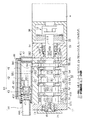
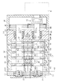
図1及び図2に示すように、多段ルーツポンプ11のロータハウジング12の前端にはフロントハウジング13が接合されており、ロータハウジング12の後端にはリヤハウジング14が接合されている。ロータハウジング12、フロントハウジング13及びリヤハウジング14は、多段ルーツポンプ11のポンプ機構を収容するハウジングを構成する。
【0023】
前記ロータハウジング12、フロントハウジング13及びリヤハウジング14は、それぞれ鉄系の金属材料により構成されている。鉄系の金属材料は、例えばアルミニウム系の金属材料と比較して熱膨張率が小さい。従って、ハウジング12〜14を鉄系金属製とすることで、熱影響による各部のクリアランスの変動を小さくすることができ、ガス漏れ等の防止に有効となる。
【0024】
次に、前記ポンプ機構について詳述する。
図1及び図2に示すように、前記ロータハウジング12は、シリンダブロック15と複数の隔壁16,16Aとからなる。フロントハウジング13と隔壁16との間の空間、及び隣合う隔壁16の間の空間は、それぞれ主ポンプ室51,52,53,54,55となっている。隔壁16Aとリヤハウジング14との間の空間は、補助ポンプ室33となっている。図4に示すように、シリンダブロック15は、一対のブロック片17,18からなり、隔壁16,16Aは一対の壁片161,162からなる。
【0025】
前記フロントハウジング13とリヤハウジング14とには、回転軸19がラジアルベアリング21,36を介して回転可能に支持されている。フロントハウジング13とリヤハウジング14とには、回転軸20がラジアルベアリング22,37を介して回転可能に支持されている。両回転軸19,20は互いに平行に配置されている。回転軸19,20は隔壁16,16Aに挿通されている。
【0026】
前記回転軸19には複数の主ロータ23,24,25,26,27が一体形成されており、回転軸20には同数の主ロータ28,29,30,31,32が一体形成されている。回転軸19,20には補助ロータ34,35が一体形成されている。主ロータ23〜32及び補助ロータ34,35は、回転軸19,20の軸線191,201の方向に見て同形同大の形状をなしている。主ロータ23,24,25,26,27の厚みは、この順に小さくなってゆくようにしてあり、主ロータ28,29,30,31,32の厚みも同様にこの順に小さくなってゆくようにしてある。補助ロータ34,35の厚みは、主ロータ27,32の厚みよりも小さくしてある。
【0027】
前記主ロータ23,28は、僅かの隙間を保って互いに噛合した状態で主ポンプ室51に収容されており、主ロータ24,29も同様に互いに噛合した状態で主ポンプ室52に収容されている。以下同様にして主ロータ25,30は主ポンプ室53に、主ロータ26,31は主ポンプ室54に、主ロータ27,32は主ポンプ室55にそれぞれ収容されている。補助ロータ34,35は、僅かの隙間を保って互いに噛合した状態で補助ポンプ室33に収容されている。主ポンプ室51〜55の容積の大きさは、この順に小さくなってゆくようにしてあり、補助ポンプ室33の容積の大きさは、主ポンプ室55の大きさよりも小さくしてある。
【0028】
前記主ポンプ室51〜55及び主ロータ23〜32は、主ポンプ49を構成する。補助ポンプ室33及び補助ロータ34,35は、主ポンプ49よりも排気容量の小さい補助ポンプ50を構成する。主ポンプ49と補助ポンプ50とが、多段ルーツポンプ11のポンプ機構を構成する。主ポンプ室55の一部は、主ロータ27,32によって、主排気口181に連通する準排気室551に区画される。
【0029】
図2に示すように、前記リヤハウジング14にはギヤハウジング38が接合されている。回転軸19,20は、リヤハウジング14を貫通してギヤハウジング38内に突出しており、各回転軸19,20の突出端部には歯車39,40が互いに噛合した状態で止着されている。ギヤハウジング38には電動モータMが組み付けられている。電動モータMの駆動力は、軸継ぎ手10を介して回転軸19に伝えられ、回転軸19は、電動モータMによって図4の矢印R1の方向に回転される。回転軸20は、歯車39,40を介して電動モータMから駆動力を得ており、回転軸20は図4の矢印R2で示すように、回転軸19とは逆方向に回転する。
【0030】
前記隔壁16内には通路163が形成されている。隔壁16には通路163の入口164及び出口165が形成されている。隔壁16Aにも同様の通路163、入口164及び出口165が形成されている。隣合う主ポンプ室51,52,53,54,55は、隔壁16の通路163を介して連通している。又、主ポンプ室55と補助ポンプ室33とは、隔壁16Aの通路163を介して連通している。
【0031】
図1及び図4に示すように、前記ブロック片17には吸入口171が主ポンプ室51に連通するように形成されている。吸入口171には、図示しない半導体加工装置の排気系配管が接続されている。ブロック片18には主排気口181が主ポンプ室55に連通するように形成されている。吸入口171から主ポンプ室51に導入された半導体加工装置の気体反応生成物(例えば塩化アンモニウム。以下、ガスとする)は、主ロータ23,28の回転によって隔壁16の入口164から通路163を経由して出口165から隣の主ポンプ室52へ移送される。以下、同様にガスは、主ポンプ室の容積が小さくなってゆく順、即ち主ポンプ室52,53,54,55の順に移送される。主ポンプ室55へ移送されたガスは、主排気口181からロータハウジング12の外へ排出される。
【0032】
前記ブロック片18には、補助排気口182が補助ポンプ室33に連通するように形成されている。主ポンプ室55内のガスの一部は、補助ロータ34,35の回転によって隔壁16Aの入口164から通路163を経由して、出口165から隣の補助ポンプ室33へ移送される。補助ポンプ室33へ移送されたガスは、補助排気口182からロータハウジング12の外へ排出される。
【0033】
次に、多段ルーツポンプ11の排気側ガス経路について説明する。
図1、図3及び図4に示すように、前記シリンダブロック15において、ブロック片18の外面のリヤハウジング14寄りの位置には、排気フランジ41が接合固定されている。排気フランジ41の内空間411は、主ポンプ49の主排気口181に連通されている。ブロック片18の外面において、排気フランジ41に対してフロントハウジング13側で連続する位置には、マフラ42が接合固定されている。排気フランジ41及びマフラ42は、腐食性のガスに対する耐食性を確保するために、それぞれ鉄系の金属材料により構成されている。排気フランジ41及びマフラ42は、全体として直方体状をなしてブロック片18の外面から突出されている。
【0034】
なお、本実施形態において、前記排気フランジ41及びマフラ42はブロック片18と別体であるが、排気フランジ41の少なくとも一部及び/又はマフラ42の少なくとも一部を、ブロック片18に一体形成するようにしてもよい。
【0035】
前記マフラ42の前端側には、ガイド管43が嵌合固定されている。ガイド管43の前端側には、排出管44が挿入固定されている。排出管44には、ガスを処理するための図示しない排気ガス処理装置が接続されている。ガイド管43及び排出管44は、耐食性に優れるステンレス鋼製である。
【0036】
前記排気フランジ41の内空間411、マフラ42の内空間421、ガイド管43の内空間432及び排出管44の内空間441は、主ポンプ49の主排気口181から排出されたガスを排気ガス処理装置へ向けて送り出すための排気通路611を構成する。つまり、排気フランジ41、マフラ42、ガイド管43及び排出管44は、多段ルーツポンプ11においてハウジング12〜14の外側に突設された、排気通路形成部61として把握することができる。
【0037】
前記ガイド管43の内空間432には、弁体45及び復帰ばね46が収容されている。ガイド管43の内空間432にはテーパ形状の弁孔431が形成されており、弁体45は弁孔431を開閉する。復帰ばね46は、弁孔431を閉じる位置に向けて弁体45を付勢する。ガイド管43、弁体45及び復帰ばね46は、排出管44側のガスがマフラ42側へ逆流することを防止するための逆流防止手段をなしている。
【0038】
前記補助排気口182には排気フランジ47が接続されており、排気フランジ47には補助排気管48が接続されている。補助排気管48は、ガイド管43に接続されている。補助排気管48とガイド管43との接続位置は、弁体45による弁孔431の開閉位置よりも下流側である。
【0039】
そして、前記電動モータMが作動すると、回転軸19,20が回転し、半導体加工装置内のガスが、吸入口171を経由して主ポンプ49の主ポンプ室51へ吸入される。主ポンプ室51に吸入されたガスは、主ポンプ室52〜55側へ圧縮されながら移動する。ガス流量が多い場合には、主ポンプ室55へ移動したガスの大部分は、主排気口181から排気通路611へ排出され、一部が補助ポンプ50の作用によって補助排気口182から排気フランジ47内へ排出され、排気フランジ47から補助排気管48を介して弁体45よりも下流側で排気通路611に合流される。
【0040】
このように、前記補助ポンプ50を備えることで、主ポンプ49の排気側の圧力を低下させることができる。従って、排気通路611内において弁体45の開閉位置よりも上流側のガスが、主ポンプ49の主ポンプ室55へ逆流することを防止できる。よって、多段ルーツポンプ11の動力損失を軽減することが可能となる。
【0041】
次に、排気通路611内における反応生成物の固化防止構造について説明する。
前記「従来技術」においても述べたように、多段ルーツポンプ11においては、ハウジング12〜14の外側に突設された排気通路形成部61が、主ポンプ49の発熱影響を受け難いことと肉厚が薄いこととから、ハウジング12〜14よりも低温となりがちである。従って、主ポンプ49から排出された反応生成物が、排気通路611を通過する際に冷却されて固化してしまう危惧がある。なお、排気通路形成部61の肉厚が薄くされているのは、ハウジング12〜14の剛性に影響を与えない当該排気通路形成部61の肉量を減らして、多段ルーツポンプ11の軽量化を図るためである。
【0042】
特に、前記排気通路形成部61において、ガス流に関する上流側部位(排気フランジ41付近)は、主ポンプ49との接続位置たる主排気口181に近いために、その熱影響を受けて比較的高温となり、逆に下流側部位(ガイド管43及び排出管44付近)は主ポンプ49の主排気口181から遠いために、上流側部位よりも低温となりがちである。従って、前述した、排気通路611内での反応生成物の固化は、上流側部位よりも下流側部位の方が発生し易い。このような問題を解決するためには、排気通路形成部61において下流側部位の温度を高めるようにすればよい。
【0043】
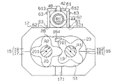
そこで、図3及び図4に示すように、本実施形態においては、前記排気通路形成部61の外面に熱伝導体62が接合固定されている。熱伝導体62は、排気通路形成部61を構成する材料(鉄系の金属材料)よりも熱伝導率の大きな金属材料(例えばアルミニウム系の金属材料又は真鍮)からなっている。熱伝導体62は矩形の平板状をなしており、排気通路形成部61の外面の一部(612,613)において、排気フランジ41からマフラ42にかけての矩形領域を覆うように配置されている。熱伝導体62においてハウジング12〜14側の端面621は、当該ハウジング12〜14の外面(詳しくはブロック片18の外面)に当接されている。排気通路形成部61に対する熱伝導体62の固定には、金属製のボルト63が用いられている。
【0044】
図4に示すように、前記排気通路形成部61において直方体状の部分(排気フランジ41及びマフラ42)には、その長手方向の両側面612,613にそれぞれ熱伝導体62が取着されている。つまり、熱伝導体62は、排気通路611の延在方向の側方で排気通路形成部61を挟み込むように、二つが配置されている。図4において拡大円中に示すように、排気通路形成部61と熱伝導体62との接合部分には、両者61,62間の密着性つまりは熱伝導性を向上させるために、熱伝導性向上手段としての熱伝導グリース64が介在されている。熱伝導グリース64としては、例えばシリコングリースが挙げられる。
【0045】
このように、前記排気通路形成部61の外面に熱伝導体62を接合固定することで、当該排気通路形成部61における上流側部位(排気フランジ41付近)の熱が、熱伝導体62を介して下流側部位(ガイド管43及び排出管44付近)に効率良く伝達されることとなる。従って、排気通路形成部61の下流側部位の温度を、例えば熱伝導体62を備えない場合と比較して高くすることができ、当該下流側部位に対応した排気通路611内での反応生成物の固化を防止することができる。よって、排気通路611の内壁面に多量の反応生成物が付着されることによる、多段ルーツポンプ11の性能低下を防止することが可能となる。
【0046】
上記構成の本実施形態においては次のような効果を奏する。
(1)排気通路形成部61の外面に熱伝導体62を接合固定することで、当該排気通路形成部61の下流側部位に対応した排気通路611内での反応生成物の固化を防止するようにしている。このように、ポンプ機構49,50の発熱を利用して排気通路形成部61の下流側部位の温度を高める手法は、例えば、排気通路形成部61にヒータを設けた場合のような電源設備を必要とせず、半導体製造プロセスの設備コスト及びランニングコストを抑えることが可能となる。また、熱伝導体62は排気通路形成部61と別体であるため、当該排気通路形成部61(詳しくは排気通路611の内壁面)を構成する材料の選択の自由度が増す。従って、排気通路形成部61を耐食性に優れる材料により構成することで、多段ルーツポンプ11の耐久性低下を防止することができる。
【0047】
以上のように本実施形態によれば、ポンプ機構49,50の発熱を利用した反応生成物の固化防止と、多段ルーツポンプ11の耐久性低下の防止とを両立することが可能となる。従って、半導体製造プロセスに用いるのに特に好適な多段ルーツポンプ11となる。
【0048】
また、前記熱伝導体62は、ガス流に曝されることのない排気通路形成部61の外面に接合固定されるため、例えば、ガス流に曝される言い換えればガスの流路を構成するヒートパイプでは必要であった、高精度加工を必要としない。従って、熱伝導体62を安価に製作することができ、多段ルーツポンプ11の製造コスト低減に貢献される。
【0049】
(2)平板状をなす熱伝導体62はその製作が容易であるし、排気通路形成部61に対する組み付けも簡単である。従って、多段ルーツポンプ11に対する、反応生成物の固化防止構造の適用が容易となる。
【0050】
(3)熱伝導体62においてハウジング12〜14側の端面621は、当該ハウジング12〜14の外面(詳しくはブロック片18の外面)に当接されている。従って、熱伝導体62には、ブロック片18からも、主排気口181近傍の熱が直接的に伝達されることとなる。よって、排気通路形成部61の下流側部位の温度を効率良く高めることができ、排気通路611内における反応生成物の固化の防止がより確実となる。
【0051】
(4)排気通路形成部61に対する熱伝導体62の固定には、金属製のボルト63が用いられている。つまり、ボルト63の先端は排気通路形成部61に螺入されており、熱伝導体62は、排気通路形成部61の外面のみならず肉内部に対しても、ボルト63を介して熱的に結合されている。従って、排気通路形成部61と熱伝導体62との間の熱伝導性が向上され、排気通路形成部61の下流側部位の温度を効率良く高めることができ、排気通路611内における反応生成物の固化の防止がより確実となる。
【0052】
(5)排気通路形成部61と熱伝導体62との間に熱伝導グリース64を介在させることで、両者61,62間の熱伝導性が向上される。従って、排気通路形成部61の上流側部位から熱伝導体62への熱伝達、及び熱伝導体62から下流側部位への熱伝達がそれぞれ効率良く行われ、当該下流側部位の温度を効率良く高めることができる。よって、排気通路611内における反応生成物の固化の防止がより確実となる。
【0053】
(6)熱伝導体62は、排気通路611の延在方向の両側で排気通路形成部61を挟み込むように、二つが配置されている。従って、排気通路形成部61の上流側部位の熱を下流側部位へ効率良く伝達することができ、当該下流側部位の温度を効率良く高めることができる。よって、排気通路611内における反応生成物の固化の防止がより確実となる。
【0054】
なお、本発明の趣旨から逸脱しない範囲で例えば以下の態様でも実施できる。・図5に示すように、平板を「L」字状に曲折して熱伝導体62とすること。平板を曲折する作業は容易であり、本態様においても上記実施形態の(2)と同様な効果を奏する。また、熱伝導体62における、ハウジング12〜14の外面(詳しくはブロック片18の外面)との接触面621の面積が、上記第1実施形態と比較して増大される。従って、熱伝導体62とブロック片18との間の熱伝導率が高められ、上記実施形態の効果(3)がより効果的に奏される。
【0055】
・図6に示すように、平板を「コ」字状に曲折して熱伝導体62とするとともに、当該熱伝導体62を、排気通路611の延在方向の側方で排気通路形成部61を挟み込むように配置すること。別の見方をすれば、排気通路611の延在方向の側方で排気通路形成部61を挟み込む態様を、一つの熱伝導体62で達成するよう当該熱伝導体62の形状を設定すること。このように熱伝導体62を一つとすることで、多段ルーツポンプ11の組立時における当該熱伝導体62の取り扱いが容易となり、組立工程を簡略化することができる。
【0056】
・上記実施形態の熱伝導体62は、排気通路形成部61において排気フランジ41及びマフラ42の外面にのみ接合される構成であった。これを変更し、熱伝導体62を大きくするか或いは多数準備することで、ガイド管43及び/又は排出管44の外面にも熱伝導体62が接合されるようにすること。この場合、ガイド管43及び排出管44は横断面の外形が円形であるため、その外面に接合される熱伝導体62は横断面が円弧状となるように湾曲させる必要がある。このようにすれば、熱伝導体62の熱が、ガイド管43及び/又は排出管44へ直接伝達されるため、排気通路形成部61の下流側部位の温度をより効率よく高めることができる。
【0057】
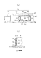
・熱伝導体は固体に限定されるものではなく、液体であってもよい。つまり例えば、図7(a)及び図7(b)に示すように、排気通路形成部61の少なくとも排気フランジ41及びマフラ42を樹脂製とする。また、上記実施形態の熱伝導体62を、排気通路形成部61と同じ樹脂製とするとともに中空状に変更することで、当該熱伝導体を単なる密閉容器62として把握する。そして、この密閉容器62内に、排気通路形成部61を構成する樹脂材料よりも熱伝導率の大きな、液体(例えば水銀)からなる熱伝導体65を封入すること。
【0058】
・上記実施形態の熱伝導グリース64を変更し、排気通路形成部61と熱伝導体62との接合部分に、熱伝導性向上手段としての銅ペースト又は樹脂シート或いはゴムシートを介在させること。
【0059】
・ルーツポンプ以外の真空ポンプ(例えばスクリューポンプ)に本発明を適用すること。
上記実施形態から把握できる技術的思想について記載する。
【0060】
(1)前記熱伝導体は、金属製のボルトを介して排気通路形成部に固定されている請求項1〜5のいずれかに記載の真空ポンプ。
(2)前記熱伝導体は、排気通路の延在方向の側方で排気通路形成部を挟み込むよう、複数が配置されている請求項4に記載の真空ポンプ。
【0061】
(3)前記熱伝導体は、排気通路の延在方向の側方で排気通路形成部を挟み込む形状をなしている請求項4に記載の真空ポンプ。
【0062】
【発明の効果】
上記構成の本発明によれば、ポンプ機構の発熱を利用して排気通路形成部の温度を高めることを、真空ポンプの耐久性の低下なく達成可能となる。
【図面の簡単な説明】
【図1】真空ポンプの側断面図。
【図2】真空ポンプの平断面図。
【図3】真空ポンプの要部を示す側面図。
【図4】図2のA−A線断面図。
【図5】別例の真空ポンプの横断面図。
【図6】別の別例の真空ポンプの横断面図。
【図7】(a)は別の別例の真空ポンプの要部を示す側面図、(b)は(a)のB−B線断面図。
【符号の説明】
11…真空ポンプとしての多段ルーツポンプ、12…ハウジングを構成するロータハウジング、13…同じくフロントハウジング、14…同じくリヤハウジング、61…排気通路形成部、611…排気通路、62…熱伝導体、64…熱伝導性向上手段としての熱伝導グリース、65…熱伝導体。[0001]
TECHNICAL FIELD OF THE INVENTION
The present invention relates to a vacuum pump used for a semiconductor manufacturing process, for example.
[0002]
[Prior art]
In a semiconductor manufacturing process, a gaseous reaction product (hereinafter, referred to as a gas) generated in a semiconductor processing apparatus is exhausted using a vacuum pump. The vacuum pump has a pump mechanism housed in a housing. On the outside of the housing, an exhaust passage forming portion connected to an external exhaust gas treatment device is protruded. Therefore, the gas discharged from the pump mechanism is led to the exhaust gas processing device via the exhaust passage formed in the exhaust passage forming portion.
[0003]
In the vacuum pump, the temperature of the exhaust passage forming portion located outside the housing is lower than that of the housing because the heat generating effect of the pump mechanism is hardly affected and the wall thickness is thin. Therefore, the reaction product discharged from the pump mechanism is cooled and solidified when passing through the exhaust passage, and may adhere to the inner wall surface of the passage. If a large amount of the reaction product adheres to the inner wall surface of the exhaust passage, the location where the reaction product adheres acts as a gas flow restrictor, causing a problem that the performance of the vacuum pump is reduced.
[0004]
Particularly, in the exhaust passage forming portion, the upstream portion relating to the gas flow is relatively close to the connection position with the pump mechanism (the exhaust port of the pump mechanism), so that the temperature becomes relatively high under the influence of the heat, and conversely, the downstream side Since the part is far from the connection position with the pump mechanism, the temperature is lower than that of the upstream part. Therefore, the problem of the adhesion of the reaction product to the inner wall surface of the exhaust passage is more likely to occur in the downstream portion than in the upstream portion.
[0005]
In order to solve such a problem, it is only necessary to increase the temperature of a portion where the reaction product is likely to be solidified, and for that purpose, for example, the following technique may be employed.
Prior art (1): A portion where the reaction product is likely to be solidified is heated using a heater (for example, see Patent Document 1).
[0006]
Prior art (2): By forming the housing from an aluminum-based metal material having excellent thermal conductivity, heat generated by the pump mechanism is efficiently transmitted to a portion where the reaction product is likely to be solidified. (For example, see Patent Document 2).
[0007]
Prior art (3): A heat pipe is inserted and arranged at a position where a reaction product is likely to solidify (for example, see Patent Document 3).
[0008]
[Patent Document 1]
JP-A-8-78300 (page 2, FIG. 1)
[Patent Document 2]
JP-A-8-296557 (page 3, FIG. 1)
[Patent Document 3]
JP-A-1-167497 (page 2, FIG. 1)
[0009]
[Problems to be solved by the invention]
However, each of the above prior arts has the following problems.
Prior art (1): Providing a heater requires the provision of a separate power supply facility, which has led to an increase in equipment costs of the semiconductor manufacturing process. Further, there is also a problem that the running cost is increased by the amount that the heater needs to generate heat.
[0010]
Prior art (2): In a semiconductor manufacturing process, a highly corrosive gas (for example, ammonium chloride) is handled. Therefore, when the housing is made of an aluminum-based metal material having poor corrosion resistance, the durability of the vacuum pump is reduced. Further, an aluminum-based metal material has a large thermal expansion as compared with, for example, an iron-based metal material, and there is a fear that gas leakage may occur due to a large variation in clearance of each part.
[0011]
Prior art (3): To increase the thermal conductivity of the heat pipe, the heat pipe must be made of an aluminum-based metal material, brass, or the like. Will happen. Further, since gas flows through the hollow portion of the heat pipe, in other words, since the heat pipe forms a gas flow path, it is necessary to accurately process the inner diameter and the like of the heat pipe, resulting in an increase in cost.
[0012]
An object of the present invention is to provide a vacuum pump capable of increasing the temperature of an exhaust passage forming portion by using heat generated by a pump mechanism without lowering durability.
[0013]
[Means for Solving the Problems]
According to a first aspect of the present invention, there is provided a vacuum pump, wherein a material having a higher thermal conductivity than a material forming the exhaust passage forming portion is provided on an outer surface of the exhaust passage forming portion protruding outside the housing. Is fixed by bonding. In the exhaust passage forming portion, the upstream portion related to the gas flow is close to the connection position with the pump mechanism (exhaust port of the pump mechanism), so that the temperature becomes high due to its thermal influence. Therefore, the heat of the upstream portion of the exhaust passage forming portion is efficiently transmitted to the downstream portion via the heat conductor, and the temperature of the downstream portion is higher than, for example, a case where the heat conductor is not provided. can do.
[0014]
As described above, the method of increasing the temperature of the downstream portion of the exhaust passage forming portion by using the heat generated by the pump mechanism does not require power supply equipment as in the case where a heater is provided in the exhaust passage forming portion, for example, and requires equipment cost. And running costs can be reduced. Further, since the heat conductor is separate from the exhaust passage forming portion, the degree of freedom in selecting a material forming the exhaust passage forming portion is increased. Therefore, for example, when a corrosive gas is handled, a reduction in the durability of the vacuum pump can be prevented by configuring the exhaust passage forming portion with a material having excellent corrosion resistance.
[0015]
As described above, according to the present invention, it is possible to simultaneously increase the temperature of the downstream portion of the exhaust passage forming portion by using the heat generated by the pump mechanism and prevent the durability of the vacuum pump from being reduced. .
[0016]
Further, since the heat conductor is bonded and fixed to the outer surface of the exhaust passage forming portion that is not exposed to the gas flow, for example, in a heat pipe that is exposed to the gas flow, in other words, configures a gas flow path. It does not require high precision machining, which was necessary. Therefore, the heat conductor can be manufactured at low cost, which contributes to a reduction in the manufacturing cost of the vacuum pump.
[0017]
According to a second aspect of the present invention, in the first aspect, the heat conductor has a flat plate shape or a shape obtained by bending a flat plate. The heat conductor having the shape of a flat plate or a bent flat plate can be easily manufactured, and can be easily assembled to the exhaust passage forming portion.
[0018]
According to a third aspect of the present invention, in the first or second aspect, a thermal conductivity improving means is provided between the thermal conductor and the exhaust passage forming portion for bringing the two into close contact with each other to improve thermal conductivity. ing. Therefore, heat transfer from the upstream portion of the exhaust passage forming portion to the heat conductor and heat transfer from the heat conductor to the downstream portion are efficiently performed, and the temperature of the downstream portion can be efficiently increased. it can.
[0019]
According to a fourth aspect of the present invention, in any one of the first to third aspects, the heat conductor sandwiches the exhaust passage forming portion on the side in the extending direction of the exhaust passage. Therefore, the heat of the upstream portion of the exhaust passage forming portion can be efficiently transmitted to the downstream portion, and the temperature of the downstream portion can be efficiently increased.
[0020]
In a fifth aspect of the present invention, in any one of the first to fourth aspects, the gas is a gaseous reaction product generated in a semiconductor processing apparatus. Therefore, by increasing the temperature of the downstream portion of the exhaust passage forming portion via the heat conductor, it is possible to prevent solidification or liquefaction of the reaction product in the exhaust passage corresponding to the downstream portion. Therefore, it is possible to prevent the performance of the vacuum pump from deteriorating due to a large amount of reaction products being attached to the inner wall surface of the exhaust passage.
[0021]
BEST MODE FOR CARRYING OUT THE INVENTION
Hereinafter, an embodiment in which the present invention is embodied in a vacuum pump used in a semiconductor manufacturing process will be described.
[0022]
First, the housing of the multi-stage roots pump 11 as a vacuum pump will be described.
As shown in FIGS. 1 and 2, a
[0023]
The
[0024]
Next, the pump mechanism will be described in detail.
As shown in FIGS. 1 and 2, the
[0025]
A rotating
[0026]
A plurality of
[0027]
The
[0028]
The
[0029]
As shown in FIG. 2, a
[0030]
A
[0031]
As shown in FIGS. 1 and 4, a
[0032]
An
[0033]
Next, the exhaust gas path of the multi-stage roots pump 11 will be described.
As shown in FIGS. 1, 3 and 4, in the
[0034]
In the present embodiment, the
[0035]
A
[0036]
The
[0037]
The
[0038]
An
[0039]
When the electric motor M operates, the rotating
[0040]
Thus, by providing the
[0041]
Next, a structure for preventing the reaction product from solidifying in the
As described in the above-mentioned “prior art”, in the multi-stage roots pump 11, the exhaust
[0042]
Particularly, in the exhaust
[0043]
Therefore, as shown in FIGS. 3 and 4, in the present embodiment, a
[0044]
As shown in FIG. 4, the
[0045]
As described above, by joining and fixing the
[0046]
The present embodiment having the above configuration has the following effects.
(1) By bonding and fixing the
[0047]
As described above, according to the present embodiment, it is possible to achieve both the prevention of the solidification of the reaction product using the heat generated by the
[0048]
Further, since the
[0049]
(2) The flat plate-shaped
[0050]
(3) The
[0051]
(4) A
[0052]
(5) By interposing the thermal
[0053]
(6) Two
[0054]
It should be noted that, for example, the following embodiments can be implemented without departing from the spirit of the present invention. As shown in FIG. 5, a flat plate is bent into an “L” shape to form the
[0055]
As shown in FIG. 6, the flat plate is bent into a “U” shape to form the
[0056]
The
[0057]
-The heat conductor is not limited to a solid, but may be a liquid. That is, for example, as shown in FIGS. 7A and 7B, at least the
[0058]
The
[0059]
Applying the present invention to a vacuum pump (for example, a screw pump) other than the roots pump.
The technical idea that can be grasped from the above embodiment will be described.
[0060]
(1) The vacuum pump according to any one of claims 1 to 5, wherein the heat conductor is fixed to the exhaust passage forming portion via a metal bolt.
(2) The vacuum pump according to claim 4, wherein a plurality of the heat conductors are arranged so as to sandwich the exhaust passage forming portion on the side in the extending direction of the exhaust passage.
[0061]
(3) The vacuum pump according to claim 4, wherein the heat conductor has a shape sandwiching the exhaust passage forming portion on the side in the extending direction of the exhaust passage.
[0062]
【The invention's effect】
According to the present invention having the above configuration, it is possible to increase the temperature of the exhaust passage forming portion by using the heat generated by the pump mechanism without lowering the durability of the vacuum pump.
[Brief description of the drawings]
FIG. 1 is a side sectional view of a vacuum pump.
FIG. 2 is a plan sectional view of a vacuum pump.
FIG. 3 is a side view showing a main part of the vacuum pump.
FIG. 4 is a sectional view taken along line AA of FIG. 2;
FIG. 5 is a cross-sectional view of another example of a vacuum pump.
FIG. 6 is a cross-sectional view of another example of a vacuum pump.
FIG. 7A is a side view showing a main part of another another example of a vacuum pump, and FIG. 7B is a sectional view taken along line BB of FIG.
[Explanation of symbols]
Claims (5)
前記排気通路形成部の外面に、当該排気通路形成部を構成する材料よりも熱伝導率の大きい材料からなる熱伝導体が接合固定されてなることを特徴とする真空ポンプ。An exhaust passage forming portion is provided outside the housing that houses the pump mechanism.
A vacuum pump, wherein a heat conductor made of a material having a higher thermal conductivity than a material forming the exhaust passage forming portion is bonded and fixed to an outer surface of the exhaust passage forming portion.
Priority Applications (7)
| Application Number | Priority Date | Filing Date | Title |
|---|---|---|---|
| JP2002264326A JP4007130B2 (en) | 2002-09-10 | 2002-09-10 | Vacuum pump |
| TW092124695A TWI232267B (en) | 2002-09-10 | 2003-09-08 | Vacuum pump |
| US10/658,155 US6874989B2 (en) | 2002-09-10 | 2003-09-08 | Vacuum pump |
| DE60328652T DE60328652D1 (en) | 2002-09-10 | 2003-09-09 | Multi-stage Roots-type vacuum pump |
| KR1020030063020A KR100555189B1 (en) | 2002-09-10 | 2003-09-09 | Vacuum pump |
| EP03020357A EP1398507B1 (en) | 2002-09-10 | 2003-09-09 | Multistage Roots-type vacuum pump |
| CNB031584616A CN1262765C (en) | 2002-09-10 | 2003-09-10 | Vacuum pump |
Applications Claiming Priority (1)
| Application Number | Priority Date | Filing Date | Title |
|---|---|---|---|
| JP2002264326A JP4007130B2 (en) | 2002-09-10 | 2002-09-10 | Vacuum pump |
Publications (2)
| Publication Number | Publication Date |
|---|---|
| JP2004100593A true JP2004100593A (en) | 2004-04-02 |
| JP4007130B2 JP4007130B2 (en) | 2007-11-14 |
Family
ID=31884756
Family Applications (1)
| Application Number | Title | Priority Date | Filing Date |
|---|---|---|---|
| JP2002264326A Expired - Fee Related JP4007130B2 (en) | 2002-09-10 | 2002-09-10 | Vacuum pump |
Country Status (7)
| Country | Link |
|---|---|
| US (1) | US6874989B2 (en) |
| EP (1) | EP1398507B1 (en) |
| JP (1) | JP4007130B2 (en) |
| KR (1) | KR100555189B1 (en) |
| CN (1) | CN1262765C (en) |
| DE (1) | DE60328652D1 (en) |
| TW (1) | TWI232267B (en) |
Cited By (4)
| Publication number | Priority date | Publication date | Assignee | Title |
|---|---|---|---|---|
| JP2012525534A (en) * | 2009-04-29 | 2012-10-22 | エドワーズ リミテッド | Vacuum pump |
| KR101760550B1 (en) | 2011-06-02 | 2017-07-21 | 가부시키가이샤 에바라 세이사꾸쇼 | Vacuum pump |
| KR101760549B1 (en) | 2011-06-02 | 2017-07-21 | 가부시키가이샤 에바라 세이사꾸쇼 | Vacuum pump |
| KR20230003575A (en) * | 2020-05-29 | 2023-01-06 | 레온 지도키 가부시키가이샤 | food material conveying device |
Families Citing this family (9)
| Publication number | Priority date | Publication date | Assignee | Title |
|---|---|---|---|---|
| JP2004278502A (en) * | 2003-01-24 | 2004-10-07 | Toyota Industries Corp | Multi-stage gear pump |
| GB0406748D0 (en) * | 2004-03-26 | 2004-04-28 | Boc Group Plc | Vacuum pump |
| GB0620144D0 (en) | 2006-10-11 | 2006-11-22 | Boc Group Plc | Vacuum pump |
| US8821140B2 (en) * | 2010-04-29 | 2014-09-02 | Dan Paval | Gear pump |
| GB2487376A (en) * | 2011-01-19 | 2012-07-25 | Edwards Ltd | Two material pump stator for corrosion resistance and thermal conductivity |
| JP2013238210A (en) * | 2012-05-17 | 2013-11-28 | Mikuni Corp | Multistage oil pump |
| CN107035692A (en) * | 2016-02-04 | 2017-08-11 | 张权 | A kind of vacuum system performance degradation measuring method based on lobe pump fault mode |
| JP7261139B2 (en) * | 2019-10-15 | 2023-04-19 | 株式会社荏原製作所 | vacuum pump equipment |
| GB2642860A (en) * | 2024-07-23 | 2026-01-28 | Edwards Ltd | Vacuum pump housing |
Family Cites Families (12)
| Publication number | Priority date | Publication date | Assignee | Title |
|---|---|---|---|---|
| US4549857A (en) * | 1984-08-03 | 1985-10-29 | Carrier Corporation | Hermetic motor compressor having a suction inlet and seal |
| JPS6419198A (en) | 1987-07-15 | 1989-01-23 | Hitachi Ltd | Vacuum pump |
| JPH01167497A (en) | 1987-12-23 | 1989-07-03 | Hitachi Ltd | Vacuum pump |
| US5618167A (en) * | 1994-07-28 | 1997-04-08 | Ebara Corporation | Vacuum pump apparatus having peltier elements for cooling the motor & bearing housing and heating the outer housing |
| JPH0878300A (en) | 1994-09-06 | 1996-03-22 | Sony Corp | Vacuum exhaust mechanism |
| KR0143142B1 (en) * | 1995-03-07 | 1998-08-01 | 김광호 | Cylinder device of reciprocating compressor |
| JP3563152B2 (en) | 1995-04-21 | 2004-09-08 | 株式会社アルバック | Vacuum pump |
| JP3734613B2 (en) * | 1997-12-26 | 2006-01-11 | 株式会社荏原製作所 | Turbo molecular pump |
| JP2002048088A (en) * | 2000-07-31 | 2002-02-15 | Seiko Instruments Inc | Vacuum pump |
| JP2002115682A (en) * | 2000-10-12 | 2002-04-19 | Toyota Industries Corp | Cooling structure in vacuum pump |
| JP2002130170A (en) * | 2000-10-23 | 2002-05-09 | Toyota Industries Corp | Channel structure in vacuum pump |
| JP4657463B2 (en) * | 2001-02-01 | 2011-03-23 | エドワーズ株式会社 | Vacuum pump |
-
2002
- 2002-09-10 JP JP2002264326A patent/JP4007130B2/en not_active Expired - Fee Related
-
2003
- 2003-09-08 US US10/658,155 patent/US6874989B2/en not_active Expired - Fee Related
- 2003-09-08 TW TW092124695A patent/TWI232267B/en not_active IP Right Cessation
- 2003-09-09 DE DE60328652T patent/DE60328652D1/en not_active Expired - Lifetime
- 2003-09-09 EP EP03020357A patent/EP1398507B1/en not_active Expired - Lifetime
- 2003-09-09 KR KR1020030063020A patent/KR100555189B1/en not_active Expired - Fee Related
- 2003-09-10 CN CNB031584616A patent/CN1262765C/en not_active Expired - Fee Related
Cited By (5)
| Publication number | Priority date | Publication date | Assignee | Title |
|---|---|---|---|---|
| JP2012525534A (en) * | 2009-04-29 | 2012-10-22 | エドワーズ リミテッド | Vacuum pump |
| KR101760550B1 (en) | 2011-06-02 | 2017-07-21 | 가부시키가이샤 에바라 세이사꾸쇼 | Vacuum pump |
| KR101760549B1 (en) | 2011-06-02 | 2017-07-21 | 가부시키가이샤 에바라 세이사꾸쇼 | Vacuum pump |
| KR20230003575A (en) * | 2020-05-29 | 2023-01-06 | 레온 지도키 가부시키가이샤 | food material conveying device |
| KR102861098B1 (en) | 2020-05-29 | 2025-09-16 | 레온 지도키 가부시키가이샤 | Food material transport device |
Also Published As
| Publication number | Publication date |
|---|---|
| US6874989B2 (en) | 2005-04-05 |
| EP1398507A2 (en) | 2004-03-17 |
| KR100555189B1 (en) | 2006-03-03 |
| TWI232267B (en) | 2005-05-11 |
| CN1262765C (en) | 2006-07-05 |
| KR20040023766A (en) | 2004-03-18 |
| CN1490526A (en) | 2004-04-21 |
| US20040047755A1 (en) | 2004-03-11 |
| EP1398507A3 (en) | 2006-04-19 |
| TW200404958A (en) | 2004-04-01 |
| DE60328652D1 (en) | 2009-09-17 |
| EP1398507B1 (en) | 2009-08-05 |
| JP4007130B2 (en) | 2007-11-14 |
Similar Documents
| Publication | Publication Date | Title |
|---|---|---|
| JP4007130B2 (en) | Vacuum pump | |
| TWI601880B (en) | Pump | |
| TW200404125A (en) | Vacuum pump | |
| CN114789639A (en) | Fluid management device | |
| JP5522158B2 (en) | Compressor | |
| EP3808982B1 (en) | Vacuum pump with thermal insulation | |
| JP2021063503A (en) | Vacuum pump device | |
| TW200426307A (en) | Roots pump | |
| CN100394030C (en) | Rotary vane air pump | |
| JP2002221172A (en) | Scroll compressor | |
| TW201910637A (en) | Vacuum pump | |
| JP7555870B2 (en) | Vacuum Pump Equipment | |
| JP2002130170A (en) | Channel structure in vacuum pump | |
| DE502004008629D1 (en) | A motor pump assembly | |
| WO2018025880A1 (en) | Double rotating scroll-type compressor | |
| JP2002115690A (en) | Cooling structure in vacuum pump | |
| JP7620057B1 (en) | Heat exchanger with thermoelectric power generation function | |
| JP2002115682A (en) | Cooling structure in vacuum pump | |
| JP2002115689A (en) | Cooling structure in vacuum pump | |
| CN213511176U (en) | A booster pump and water purifier having the same | |
| JPH03100396A (en) | Compressor | |
| TW201033467A (en) | Vacuum pump | |
| JP2002257066A (en) | Scroll fluid machine | |
| JPH03100397A (en) | compressor | |
| JPH06597Y2 (en) | Lubrication system for rotary piston engine |
Legal Events
| Date | Code | Title | Description |
|---|---|---|---|
| A621 | Written request for application examination |
Free format text: JAPANESE INTERMEDIATE CODE: A621 Effective date: 20050421 |
|
| A977 | Report on retrieval |
Free format text: JAPANESE INTERMEDIATE CODE: A971007 Effective date: 20061012 |
|
| A131 | Notification of reasons for refusal |
Free format text: JAPANESE INTERMEDIATE CODE: A131 Effective date: 20061017 |
|
| A521 | Written amendment |
Free format text: JAPANESE INTERMEDIATE CODE: A523 Effective date: 20061117 |
|
| A131 | Notification of reasons for refusal |
Free format text: JAPANESE INTERMEDIATE CODE: A131 Effective date: 20061219 |
|
| A521 | Written amendment |
Free format text: JAPANESE INTERMEDIATE CODE: A523 Effective date: 20070216 |
|
| A02 | Decision of refusal |
Free format text: JAPANESE INTERMEDIATE CODE: A02 Effective date: 20070417 |
|
| A521 | Written amendment |
Free format text: JAPANESE INTERMEDIATE CODE: A523 Effective date: 20070615 |
|
| A911 | Transfer to examiner for re-examination before appeal (zenchi) |
Free format text: JAPANESE INTERMEDIATE CODE: A911 Effective date: 20070625 |
|
| TRDD | Decision of grant or rejection written | ||
| A01 | Written decision to grant a patent or to grant a registration (utility model) |
Free format text: JAPANESE INTERMEDIATE CODE: A01 Effective date: 20070807 |
|
| A61 | First payment of annual fees (during grant procedure) |
Free format text: JAPANESE INTERMEDIATE CODE: A61 Effective date: 20070820 |
|
| FPAY | Renewal fee payment (event date is renewal date of database) |
Free format text: PAYMENT UNTIL: 20100907 Year of fee payment: 3 |
|
| FPAY | Renewal fee payment (event date is renewal date of database) |
Free format text: PAYMENT UNTIL: 20100907 Year of fee payment: 3 |
|
| FPAY | Renewal fee payment (event date is renewal date of database) |
Free format text: PAYMENT UNTIL: 20110907 Year of fee payment: 4 |
|
| FPAY | Renewal fee payment (event date is renewal date of database) |
Free format text: PAYMENT UNTIL: 20120907 Year of fee payment: 5 |
|
| FPAY | Renewal fee payment (event date is renewal date of database) |
Free format text: PAYMENT UNTIL: 20120907 Year of fee payment: 5 |
|
| FPAY | Renewal fee payment (event date is renewal date of database) |
Free format text: PAYMENT UNTIL: 20130907 Year of fee payment: 6 |
|
| LAPS | Cancellation because of no payment of annual fees |