JP2004100663A - Air conditioner - Google Patents
Air conditioner Download PDFInfo
- Publication number
- JP2004100663A JP2004100663A JP2002267540A JP2002267540A JP2004100663A JP 2004100663 A JP2004100663 A JP 2004100663A JP 2002267540 A JP2002267540 A JP 2002267540A JP 2002267540 A JP2002267540 A JP 2002267540A JP 2004100663 A JP2004100663 A JP 2004100663A
- Authority
- JP
- Japan
- Prior art keywords
- fan
- blade
- once
- air conditioner
- cross
- Prior art date
- Legal status (The legal status is an assumption and is not a legal conclusion. Google has not performed a legal analysis and makes no representation as to the accuracy of the status listed.)
- Granted
Links
Images



Landscapes
- Structures Of Non-Positive Displacement Pumps (AREA)
- Air-Conditioning Room Units, And Self-Contained Units In General (AREA)
Abstract
【課題】ルームエアコンの室内ユニットにおいて、貫流ファンの風量を増加させつつ騒音を低減させることにより、省電力で静かな空気調和機を提供する。
【解決手段】円板13に羽根12を備えた貫流ファン1において、羽根断面肉厚の中心を示す反り線17は二つの円弧を含み、それぞれの円弧の反り方向は互いに反転しており、羽根12の圧力面18は回転軸方向に対して一致する。また、羽根間流路幅は内径側に対して外径側が60〜80%の範囲で変化することで達成される。
【選択図】 図3Provided is a power-saving and quiet air conditioner in an indoor unit of a room air conditioner, which reduces noise while increasing the flow rate of a cross-flow fan.
Kind Code: A1 In a cross-flow fan provided with a blade on a disk, a warp line indicating the center of the blade cross-section includes two arcs, and the directions of warp of the respective arcs are reversed. Twelve pressure surfaces 18 coincide with the direction of the rotation axis. The width of the flow path between the blades is achieved by changing the outer diameter side in the range of 60 to 80% with respect to the inner diameter side.
[Selection diagram] FIG.
Description
【0001】
【発明の属する技術分野】
本発明は、空気調和機の室内ユニットに備えられている貫流ファンに関するものである。
【0002】
【従来の技術】
近年、空気調和機においては省電力・静音化が求められており、その省電力化のための一手法として室内ユニット内に設けられ、熱交換器内を流れる冷媒と熱交換された室内の空気を室内ユニット外に吹出すファンの風量を増大させる方法がある。室内ユニットのファンとしては壁掛け式空気調和機の場合貫流ファン(クロスフローファン)が用いられることが主流である。よく知られているように、この室内ユニットのファンの風量を増加させると室内熱交換器の熱交換性能が向上する。ファン回転数を増加させることなくファン風量を増大させることができれば、結果的に空気調和機全体の性能が向上し省電力(消費電力を変えずに)で同じ空調効果を生み出すことが可能となる。
【0003】
この室内ユニットの送風機の風量増大を図る手法として、前述の通り室内ユニットの送風機である貫流ファンの回転数を上げること、及びファンの外径を大きくすることが考えられる。
【0004】
ところで、室内ユニット動作時の乱流音(高帯域の周波数帯域に分布する音)は貫流ファンの回転数の7〜8乗に比例するので、前者の手法で風量を30%増加させる場合、9dBも増加してしまう。一方、乱流音は貫流ファンの外径の4〜5乗に比例するので、後者の手法で風量を30%増やす場合、5dBの増加に留めることができる。
【0005】
その結果、騒音(乱流音)を出来る限り増加させることなく風量を増大させるためには後者の手法が妥当であると考えられる。しかし、室内ユニットの寸法は限られており、そのため室内ユニットの内側に備え付けられている貫流ファンの大きさにも制限があり、現状より外径を大きくすることは難しくなってきている。また、貫流ファンの外径を限界まで大きくすると、貫流ファンとノーズ間の隙間が小さくなることにより際立ってくる異音(羽根枚数Zと回転数N(/sec)の積により発生する周波数Z・N(Hz)、またはその高次の周波数)、及び室内熱交換器と貫流ファンとの距離が近くなることで貫流ファンの羽根がウェーク領域(熱交換器を通過する気流の速度分布はパイプ下流が遅く、その局所的に速度分布が大きく変化している領域)に近づき、羽根がその領域を通過することにより発生する音の問題がある。
【0006】
そこで、以上の貫流ファンとの干渉による羽根音を抑えて騒音を低減させる従来技術として、特許文献1、特許文献2が知られている。これら二つの文献は、効果の違いはあっても原理的に同じであり、風量を増加させるために貫流ファンを大きくしノーズ隙間が小さくなっても騒音(羽根音)を抑える効果がある。
【0007】
すなわち、原理的には、貫流ファンの羽根外径を回転軸方向に対して変化させることで、貫流ファンの羽根外周先端構造をノーズに対して傾斜させ、その傾斜により羽根外周先端がノーズ(又は、ウェーク領域)を通過するとき時間差(位相差)がでるようにしている。
【0008】
従って、羽根外周先端とノーズの位置関係から発生する周期的音を時間的に分散させることで羽根音を抑制することができ、ノーズ隙間を小さくして高風量化を図っている。
【0009】
その他の従来技術としては特許文献3、特許文献4が知られている。これら公報に記載されている内容を説明する。貫流ファンの羽根音を防止するため、羽根の周方向取り付けピッチを不等間隔にして、各羽根の周方向の位相を異ならせることによってピーク音を抑制して全体的に騒音を低減させるというものである。
【0010】
これら特許文献1、特許文献2、特許文献3、及び特許文献4に記載された低騒音・高風量化技術は手法に違いはあるが、羽根音を周期的に分散させる点に関して共通しており、騒音(羽根音)を低減させた分風量を増加させ、空気調和機の性能を向上させることができる。
【特許文献1】
特開平9−100795号公報
【特許文献2】
特開2001−50189号公報
【特許文献3】
特開平6−129387号公報
【特許文献4】
特開平6−173886号公報
【0011】
【発明が解決しようとする課題】
しかしながら現状において、空気調和機はより一層の省電力・静音化(低騒音・高風量化)が求められており、そのためには更なる高効率・低騒音の貫流ファンが必要となる。また、貫流ファンの音には流体により発生する広帯域の乱流音があり、上記の従来技術は周期的な羽根音を抑制できても、この乱流音を低減することはできない。このため従来技術に見られる手法のみでは更なる低騒音・省電力を実現することは難しいのが実情である。
【0012】
本発明の目的は、流体による乱流音を低減しながら低騒音にし、高風量化によって省電力化を実現するルームエアコンを提供することにある。
【0013】
【課題を解決するための手段】
上記目的は、室内ユニット内に貫流ファンを備えた空気調和機において、前記貫流ファンの羽根断面の肉厚中心を示す反り線は二つの円弧を含み、それぞれの円弧の反り方向を互いに反転させることにより達成される。
【0014】
また、上記目的は、室内ユニット内に貫流ファンを備えた空気調和機において、前記貫流ファンを構成する羽根の圧力面を回転軸方向に対して一致させることにより達成される。
【0015】
また、上記目的は、室内ユニット内に貫流ファンを備えた空気調和機において、前記貫流ファンの羽根間流路幅を内径側に対して外径側を60〜80%の範囲になるように羽根の厚さを設定することによって達成される。
【0016】
第二の手段は、室内ユニットの送風機として貫流ファンを備えている空気調和機において、ファンを構成する羽根の圧力面を回転軸方向に対して一致させた構造としたことである。圧力面を一致させることで回転軸方向の速度分布は乱れることなくバランスを整えられ、貫流ファンの性能の向上につながっている。
【0017】
第三の手段は、室内ユニットの送風機として貫流ファンを備えている空気調和機において、ファンの羽根間流路幅が内径側に対して外径側は60〜80%に変化する構造としたことである。貫流ファンは基本的に吹き出し側に向かって流体の速度が増加していく増速翼列であり、この羽根間流路幅により流体の増速の程度が決定されることになり、貫流ファン性能に多大な影響を与えることができる。
【0018】
第四の手段は、低騒音効果を高めるために、以上三つの手段の何れかに加えファンの羽根外径を回転軸方向に対して変化させた構造としたことである。羽根外径を変化させることにより、羽根の干渉に時間差(位相差)を与えることで羽根音を抑制し低騒音化を図ることができる。
【0019】
【発明の実施の形態】
本発明の一実施例を図1〜図8に基づき以下に説明する。
【0020】
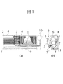
図1はルームエアコン室内ユニット全体を示しており、(a)は正面からの全体図を、(b)は室内ユニット側面からの断面を表している。ユニット全体は化粧枠2に覆われ、フィルター5、熱交換器6、貫流ファン1の順に内包された構造となっており、貫流ファン1の下方にケーシング7が設けられている。
【0021】
貫流ファン1の概観は図2に示しており、(c)は全体の形状を、(d)は回転軸方向から見た断面を表している。羽根12が円周方向に配置された円板13を一つのファンブロックとし、このファンブロックを回転軸方向に数個組み合わせることで一つの貫流ファン1が構成される。また、ファンの両端には端面円板14とボス16を備えたボス付端面円板15が取付けられており、端面円板14を軸受け側、ボス付端面円板15をモータ軸側として回転する。
【0022】
ユニットでの実際の運転状態において、貫流ファン1はモータ10により図1(b)上で右周りに回転し、化粧枠2に設けられた前面グリル3と上面グリル4から空気を吸込み、ユニット下部の吹出し口から送風する。ユニット内部での気流は、フィルター5を介して熱交換器6に到達し、この熱交換器6を通過する過程で冷やされ、または暖められる。熱交換された気流は貫流ファン1を貫通しケーシング7側に出てゆき、吹出し口付近で縦風向板8と横風向板9により風向を制御され流れ出る。
【0023】
図3、図4、図5は本実施例に係る貫流ファンの特徴を示しており、貫流ファン1を回転軸方向から見た断面の拡大図である。以下にその内容を記す。
【0024】
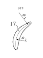
図3において、羽根12の肉厚の中心を示す反り線17は曲率半径ρ1とρ2の二円弧から形成されており、それぞれの円弧の反り方向を互いに反転させている。また、この羽根12を形成している肉厚の分布は、翼弦長の中腹から羽根外周先端、羽根内周先端の両端に向かって次第に薄くなった翼形状を形成している。
【0025】
ここで流体の性質に着目すると、一般的に流速が速くなるほど乱流音は増大することになり、また必要とする入力も増加することになる。乱流音に関しては以下の数式(1)に示されているように、貫流ファンの羽根先端を通過する流速(代表速度)V(m/s)に依存している。
【0026】
【数1】

【0027】
【数2】
【0028】
以上のことから、貫流ファン1の羽根断面形状の中心線17を二円弧で反転した構造にすれば最大流速領域となるケーシング7側の羽根外周付近における流出領域が拡大され、流体を広くゆっくり送り出すことができる。一円弧で形成された羽根(例えば、図3においてρ2のみで形成)との相違を説明する。一円弧で形成された羽根を用いた貫流ファンの流れ解析を実行し、最外周の羽根間(隣接する回転方向前方の羽根の先端から演算対象の羽根の先端)の流速分布を求めた。これによると、流速分布は一様ではなく、演算対象となる羽根の先端付近の流速が突出して速いことがわかった。前述したように流速は騒音に直接関与し、一部分のみが高流速であるため全体風量にあまり寄与していないことがわかった。そこで、本実施例では、羽根の外周側先端を半回転方向に反らせることで先の突出した高流速を抑制可能であることが判った。
【0029】
その結果、低騒音・高効率となり、省電力・風量増加を図ることで空気調和機の性能が向上することになる。その送風性能についての効果を以下に示す。図6は、図2(d)において貫流ファン1が時計回り(右回り)の場合に、曲率半径ρ1と効率ηの関係を表しており、横軸には曲率半径ρ2の反り方向を正とした場合の曲率半径ρ1の逆数をとり、縦軸には効率比η/η0をとっている。(η0は従来貫流ファンの効率を示しており、従来ファンについては図8において説明する。)性能評価の指標として用いている効率ηは貫流ファンのファン効率であり数式(3)のように表される。
【0030】
【数3】
【0031】
【数4】
【0032】
【数5】
【0033】
図4の(e)において、二つ描かれている羽根12の断面は、それぞれ回転軸方向に対して任意の位置での断面であり、その位置は一つのファンブロックを半径方向から見た断面図(f)に示している。厚く大きい断面Aは一つのファンブロックの円板3側を表し、薄く小さい断面A’はその反対側を表している。この断面図により、圧力面18は回転軸方向に対してほぼ一致していることが分かる。また(f)において、回転軸方向に対する外径変化は直径D1から直径D2へ直線的に変化しており、その関係がD1≠D2となっているのは先の従来技術で述べた羽根音を低下させる効果を加えるためである。一般的に、送風機の羽根において圧力面というものは、流体に直接動力を与える領域であり、送風性能に大きく影響する。この圧力面が歪な状態であると、流体的バランスが悪くなり不均一流れが強くなってしまい、その結果、性能低下・騒音増大といった問題が発生する。この問題は、前記の流体性質から起こることであり、根本的に同じ原理により解決することができる。その内容について以下に説明する。先述した数式(1)、(2)から判るように、騒音値・入力は代表速度Vの影響を大きく受けている。そのため、流速Vが大きくなるほど騒音は増大し、入力も増加することになる。ここで、羽根間を流出する流体の回転軸方向における速度分布に注目する。回転軸方向に対して圧力面が歪な状態とした場合、その形状が原因となり速度分布は回転軸方向に対して大きく変化する。逆に回転軸方向に対して圧力面が一致した状態の場合、速度分布はほぼ均一となり、流体は一様の流速で流出する。このとき流量を一定として、この双方の速度分布を比較し、性能に与える影響について以下に説明する。圧力面が歪な羽根は流量から計算される平均流速VaVeに対して局所的に流速Vが速い領域と遅い領域が存在し、この速度分布における各微小領域での入力は、速度の速い領域では大きくなり、速度の小さい領域では小さくなっている。そして、数式(2)に示しているように入力は流速の2乗で増加することから、この速度分布は低速域の入力低減分より高速域での入力増加分の方が多く、その結果、総入力は全体的に均一な速度分布の入力より大きくなってしまう。つまり、圧力面が一致した羽根は流量から計算される平均流速VaVeに対して全体的にほぼ同じ流速(VaVe)となっており、速度分布に関しては最も入力の少ない状態といえる。また、騒音の面から考えても数式(1)に示したように、圧力面が歪な羽根は流速Vの速い領域が存在するために騒音が増加し、圧力面が一致した羽根は最も騒音が低くなる速度分布となっている。速度分布の観点からすると、回転軸方向に圧力面が一致した羽根は速度分布が一様になることで、入力・騒音ともに最も良い状態となっている。よって、以上の様に圧力面18を回転軸方向に揃えることで、流体のバランスは改善され、送風性能の向上・静音を実現できる。
【0034】
羽根の流路幅を規定することにより性能を向上させることが可能であり、その内容を図5において説明する。(g)に示している羽根間流路幅Bは羽根内径側で最大幅Bma xとなり、羽根外径側で最小幅Bm i Nとなる。最大幅Bma xは(h)に示した羽根内径ri Nと羽根内径先端・回転軸を基点として決定した羽根間隔θによりBma x=ri NsiNθと表し、最小幅Bm i Nは羽根外径側における最小幅と定義する。この状態において、流路幅変化割合Bm i N /Bma xだけをパラメータとしてファン性能を評価した結果を図7に示す。また、羽根最大肉厚は固定し、羽根内径・外径も固定することで内外径比=一定とする条件を与え、羽根内径・外径の両端もいずれの条件において等しい形状(同じR)として比較している。効率ηは送風性能について示した貫流ファンのファン効率ηであり前記したものと定義は同じであり、貫流ファンの上流側から下流側にかけての圧力変化と流量、ファンに与えられているトルクと回転数により定まる。ここで、効率ηと流路幅変化割合Bm i N/Bma xとの関係について説明する。貫流ファンの吹出し口付近では、流量Qが一定のためBm i N/Bma xが小さくなるほど流路幅Bm i Nを通過する流体速度は大きくなる。
【0035】
しかし、流体の性質上、流体速度が大きいほど各流体領域における損失も大きくなってしまうため、貫流ファンの下流側で流速は流量Qに対応した速度分布まで下がってしまう。よって、貫流ファンによりトルクTが加えられ過剰に増速された流体は、静圧Psを上昇させることなく損失として失われるエネルギーが増えてしまう。その結果、流路幅変化割合Bm i N/Bma xが55%以下の領域については、流路幅Bm i Nが狭くなることで効率が悪くなっている。またBm i N/Bma xが大きい領域では、小さい場合とは逆に流路幅Bm i Nを通過する流体速度は小さくなる。そのため、貫流ファン吹出し口で流体は十分に増速されずに流れ出てくる。この状態で、貫流ファンにトルクTが与えられても静圧Ps、動圧Pdともに上昇せずに流体が貫流ファンを通過していく。その結果、流路幅変化割合Bm i N /Bma xが85%以上の領域において効率比η/ηma xは低い値を示し効率が悪くなっている。そして、流路幅変化割合Bm i N /Bma xが60〜80%の領域においては、静圧Ps、動圧Pd、トルクTのバランスが良いため、効率比η/ηma xは高い値を示している。以上のことから、ファンの羽根間流路幅が内径側に対して外径側は60〜80%の領域では効率が高くファン性能が向上していることが判る。室内ユニットを前記の構造範囲の貫流ファンを搭載して運転した場合は、同じ消費電力で風量を増加させることが可能となり、空気調和機全体の性能を向上させることに繋がる。
【0036】
以上は、羽根間間隔が等間隔で形成された貫流ファンで説明したが、不等間隔の貫流ファンでもこの考え方を用いることができる。以下、説明する。現在、空気調和機の室内ユニットに内装されている貫流ファンは、周方向に対して羽根が不等間隔で配置されたものが多い。つまり、貫流ファンの各羽根間のBm i N、Bma xが不等となっていることになり、各流路幅も等しくなっていない。これは前述した従来技術を応用しているためであり、貫流ファンが回転しているときの干渉による羽根音を羽根の位相をずらすことで低減する効果を持たせており、現在の空気調和機の室内ユニットに汎用されている。そのため羽根が不等間隔の貫流ファンに関して、上記の流路幅変化割合Bm i N/Bma xは各羽根間で違った値を示すことになる。そこで、以上の羽根間隔が不等の貫流ファンに対して、一意的に流路幅変化割合Bm i N/Bma xを決めるために平均化された値を用いる。一つの貫流ファンブロックの周方向にN枚の羽根が不等間隔で配置されている場合、Bma x=ri NsiN(2π/N)、Bm i N=(ΣB’m i N)/Nとする。Bma xは貫流ファンの一周を羽根枚数Nにより平均化した角度から計算され、Bm i Nは貫流ファンの各羽根間の最小流路幅をB’m i Nとしたときの全羽根間の総和(ΣB’m i N)を羽根枚数Nにより平均することで求められる。そうすることで、不等間隔の貫流ファンにおいて一意的に流路幅変化割合Bm i N/Bma xを決定することが可能となる。
【0037】
上記流路幅の調整は、基本的に羽根の厚みを調整することで対応可能である。羽根の間隔が等間隔であっても先の流路幅変化割合Bm i N /Bma xが60〜80%であれば、何れかの羽根(1枚以上の羽根)の厚さをその他の羽根の厚さと異ならせても良い(全ての羽根が同一厚さでなくても良い)し、不等間隔であっても先の平均値がその値内であれば、全ての羽根の厚さが同じでなくても良い。
【0038】
従来ファンと本実施ファンの性能比較を図8に示す。横軸に風量比Q/Q0をとり、縦軸にそれぞれ全圧比PT/PT0、入力比Lm/Lm0、騒音値SL−SL0をとっている。ここで、Q0、PT0、Lm0、SL0は従来の基準値を表している。条件は同回転数とし、従来ファンの形態は本実施ファンと同様の内外径をしており、そのため内外径比も等しくなっている。また、回転軸方向に対して羽根外径が変化しており、一つのファンブロックの軸方向における中間位置付近で最大外径となるように直線的に変化している。これは、本実施例も用いている羽根音を抑制する効果を備えていることになるが、それ以外の羽根間流路幅変化が60〜80%、二円弧が反転、圧力面を一致させた形状にはなっていない。このことから図8にも示すように、各風量比で比較すると全圧比は約+20%、入力比は約−10%、騒音値は約−1dBとなっており、本実施例により性能と騒音について改善されていることが顕著に現れている。
【0039】
【発明の効果】
本発明により、貫流ファンを高効率・低騒音化することで、風量を増加させつつ騒音を低減し、省電力で静かな空気調和機を提供できる。
【図面の簡単な説明】
【図1】本発明の一実施例形態を示す全体図。
【図2】上記の一実施例形態の貫流ファン図。
【図3】上記の一実施例形態の羽根断面拡大図。
【図4】上記の一実施例形態の羽根断面拡大図、ファンブロック断面図。
【図5】上記の一実施例形態の羽根断面拡大図、ファンブロック断面拡大図。
【図6】上記の一実施例形態の効果を示す効率図。
【図7】上記の一実施例形態の効果を示す効率図。
【図8】上記の一実施例形態の性能を示す特性図。
【符号の説明】
1…貫流ファン、2…化粧枠、3…前面グリル、4…上面グリル、5…フィルター、6…熱交換器、7…ケ−シング、8…縦風向板、9…横風向板、10…モータ、11…ノーズ、12…羽根、13…円板、14…端面円板、15…ボス付端面円板、16…ボス、17…反り線、18…圧力面。[0001]
TECHNICAL FIELD OF THE INVENTION
TECHNICAL FIELD The present invention relates to a once-through fan provided in an indoor unit of an air conditioner.
[0002]
[Prior art]
In recent years, there has been a demand for power saving and noise reduction in air conditioners. As one method for power saving, indoor air that is provided in an indoor unit and exchanges heat with a refrigerant flowing in a heat exchanger is provided. There is a method of increasing the air volume of a fan that blows air out of the indoor unit. As a fan of the indoor unit, in the case of a wall-mounted air conditioner, a cross-flow fan (crossflow fan) is mainly used. As is well known, increasing the air volume of the fan of the indoor unit improves the heat exchange performance of the indoor heat exchanger. If the fan airflow can be increased without increasing the fan speed, the overall performance of the air conditioner will eventually improve, and the same air-conditioning effect can be produced with reduced power consumption (without changing power consumption). .
[0003]
As a method of increasing the air volume of the blower of the indoor unit, it is conceivable to increase the rotation speed of the once-through fan, which is the blower of the indoor unit, and increase the outer diameter of the fan as described above.
[0004]
By the way, since the turbulent sound (sound distributed in the high frequency band) during the operation of the indoor unit is proportional to the 7th to 8th power of the rotation speed of the once-through fan, if the air volume is increased by 30% by the former method, it is 9 dB. Will also increase. On the other hand, since the turbulent sound is proportional to the outer diameter of the once-through fan to the fourth to fifth powers, when the air volume is increased by 30% by the latter method, the increase can be limited to 5 dB.
[0005]
As a result, it is considered that the latter method is appropriate for increasing the air volume without increasing the noise (turbulent sound) as much as possible. However, the size of the indoor unit is limited, and therefore, the size of the cross-flow fan provided inside the indoor unit is also limited, and it is more difficult to increase the outer diameter than at present. Further, when the outer diameter of the cross-flow fan is increased to the limit, the gap between the cross-flow fan and the nose becomes smaller, and the abnormal noise (frequency Z · generated by the product of the number of blades Z and the number of rotations N (/ sec)) becomes prominent. N (Hz) or a higher frequency thereof), and as the distance between the indoor heat exchanger and the once-through fan becomes shorter, the blades of the once-through fan move in the wake area (the velocity distribution of the airflow passing through the heat exchanger is lower than the pipe downstream). Is slow, and the velocity distribution approaches a region where the velocity distribution is largely changed), and there is a problem of a sound generated when the blade passes through the region.
[0006]
Therefore,
[0007]
That is, in principle, by changing the blade outer diameter of the once-through fan with respect to the rotation axis direction, the blade outer peripheral tip structure of the cross-flow fan is inclined with respect to the nose. , Wake area), there is a time difference (phase difference).
[0008]
Therefore, the blade sound can be suppressed by temporally dispersing the periodic sound generated from the positional relationship between the tip of the blade outer periphery and the nose, and the nose gap is reduced to increase the air volume.
[0009]
[0010]
The techniques for reducing the noise and increasing the air volume described in
[Patent Document 1]
JP-A-9-100795 [Patent Document 2]
JP 2001-50189 A [Patent Document 3]
Japanese Patent Application Laid-Open No. H6-129387 [Patent Document 4]
JP-A-6-173886 [0011]
[Problems to be solved by the invention]
However, at present, the air conditioner is required to further reduce power consumption and reduce noise (low noise and high air volume), and for that purpose, a more efficient and low noise once-through fan is required. Further, the sound of the once-through fan includes a wide-band turbulent sound generated by the fluid. Even if the above-described conventional technology can suppress the periodic blade sound, it cannot reduce the turbulent sound. For this reason, it is actually difficult to realize further low noise and power saving only by the method found in the prior art.
[0012]
An object of the present invention is to provide a room air conditioner that reduces noise while reducing turbulent noise caused by a fluid and realizes power saving by increasing the air volume.
[0013]
[Means for Solving the Problems]
The object is to provide an air conditioner having a once-through fan in an indoor unit, wherein the warp line indicating the center of thickness of the cross section of the blade of the once-through fan includes two arcs, and the warp directions of the respective arcs are reversed. Is achieved by
[0014]
Further, the above object is achieved in an air conditioner having a cross-flow fan in an indoor unit by matching the pressure surfaces of the blades constituting the cross-flow fan with respect to the rotation axis direction.
[0015]
Further, the above object is to provide an air conditioner having a cross-flow fan in an indoor unit, wherein the blades of the cross-flow fan are arranged such that the width between the blades is 60 to 80% on the outer diameter side with respect to the inner diameter side. This is achieved by setting the thickness.
[0016]
The second means is that in an air conditioner provided with a once-through fan as a blower of an indoor unit, a structure is adopted in which the pressure surfaces of the blades constituting the fan are aligned with the direction of the rotation axis. By matching the pressure surfaces, the speed distribution in the direction of the rotation axis can be balanced without being disturbed, which leads to an improvement in the performance of the once-through fan.
[0017]
A third means is that the air conditioner having a once-through fan as a blower of the indoor unit has a structure in which the width of the passage between the blades of the fan changes from 60 to 80% on the outer diameter side with respect to the inner diameter side. It is. The cross-flow fan is basically a speed-up cascade in which the speed of the fluid increases toward the blow-out side, and the degree of speed-up of the fluid is determined by the width of the flow path between the blades. Can have a great effect on
[0018]
The fourth means is a structure in which the outer diameter of the blade of the fan is changed in the rotation axis direction in addition to any one of the above three means in order to enhance the low noise effect. By changing the outer diameter of the blade, a time difference (phase difference) is given to the interference of the blade, thereby suppressing the blade sound and reducing the noise.
[0019]
BEST MODE FOR CARRYING OUT THE INVENTION
One embodiment of the present invention will be described below with reference to FIGS.
[0020]
1A and 1B show the entire indoor unit of a room air conditioner, wherein FIG. 1A is an overall view from the front, and FIG. 1B is a cross section from the side of the indoor unit. The whole unit is covered with a
[0021]
An outline of the once-through
[0022]
In the actual operation state of the unit, the once-through
[0023]
FIGS. 3, 4 and 5 show the characteristics of the cross-flow fan according to the present embodiment, and are enlarged views of the cross-section of the
[0024]
In FIG. 3, the
[0025]
Focusing on the properties of the fluid, the turbulent sound generally increases as the flow velocity increases, and the required input also increases. The turbulent noise depends on the flow velocity (representative velocity) V (m / s) passing through the tip of the blade of the once-through fan, as shown in the following equation (1).
[0026]
(Equation 1)
[0027]
(Equation 2)
[0028]
From the above, if the
[0029]
As a result, low noise and high efficiency are achieved, and the performance of the air conditioner is improved by saving power and increasing the air volume. The effects on the air blowing performance are shown below. FIG. 6 shows the relationship between the radius of curvature ρ 1 and the efficiency η when the
[0030]
[Equation 3]
[0031]
(Equation 4)
[0032]
(Equation 5)
[0033]
In FIG. 4E, the two cross-sections of the
[0034]
The performance can be improved by defining the flow path width of the blade, and the contents will be described with reference to FIG. (G) with vanes between channel width B which shows the maximum width B ma x becomes wings inner diameter side, the minimum width B m i N feathers outer diameter side. The maximum width B ma x represents the B ma x = r i N siNθ by blade spacing θ determined as a base point blades inner diameter r i N and the blade inner diameter tip and rotation axis shown in (h), the minimum width B m i N Is defined as the minimum width on the outer diameter side of the blade. In this state, the results of evaluation of the fan performance only passage width variation rate B m i N / B ma x as a parameter in FIG. Also, the maximum thickness of the blade is fixed, and the inner and outer diameters of the blade are also fixed to give a condition that the inner and outer diameter ratios are constant. Both ends of the inner and outer diameters of the blade are assumed to have the same shape (same R) under any conditions. Comparing. Efficiency η is the fan efficiency η of the once-through fan shown for the blowing performance, and the definition is the same as above, the pressure change and flow rate from the upstream side to the downstream side of the once-through fan, the torque and rotation given to the fan Determined by number. Here, the relationship between the efficiency η and the channel width change ratio B m i N / B ma x will be described. In the vicinity of air outlet of the cross-flow fan, fluid velocity flow rate Q through a constant for B m i N / B ma as x becomes smaller passage width B m i N increases.
[0035]
However, due to the nature of the fluid, the higher the fluid velocity, the greater the loss in each fluid region, and the flow velocity on the downstream side of the once-through fan drops to a velocity distribution corresponding to the flow rate Q. Therefore, the fluid excessively is accelerated torque T applied by the cross-flow fan, thus increasing energy lost as loss without increasing the static pressure P s. As a result, the channel width change ratio B m i N / B ma x is for the following regions 55% efficiency by the channel width B m i N is narrowed is deteriorated. In the B m i N / B ma x is large area, the fluid velocity through the channel width B m i N Conversely smaller decreases. Therefore, the fluid flows out at the once-through fan outlet without being sufficiently accelerated. In this state, the cross-flow fan static pressure be applied torque T in P s, is fluid without increasing dynamic pressure P d together continue to pass through the cross-flow fan. As a result, the channel width change ratio B m i N / B ma x efficiency ratio η / η ma x at 85% or more of area efficiency indicates a lower value is deteriorated. Then, in the region of the channel width change ratio B m i N / B ma x is 60-80%, static pressure P s, the dynamic pressure P d, since a good balance of torque T, the efficiency ratio η / η ma x Indicates a high value. From the above, it can be seen that the efficiency is high and the fan performance is improved in the region where the fan-to-blade flow path width is 60% to 80% on the outer diameter side relative to the inner diameter side. When the indoor unit is operated with the cross-flow fan of the above-described structural range, it is possible to increase the air flow with the same power consumption, which leads to improvement in the performance of the entire air conditioner.
[0036]
Although the above description has been made with reference to a cross-flow fan in which the intervals between the blades are formed at equal intervals, this concept can also be used with a cross-flow fan having unequal intervals. This will be described below. At present, most of the cross-flow fans installed in the indoor units of the air conditioner have blades arranged at irregular intervals in the circumferential direction. That, B m i N between the blades of the cross-flow fan, will be B ma x becomes unequal, not equal even the flow path width. This is due to the application of the above-mentioned conventional technology, which has the effect of reducing the blade sound caused by interference when the cross-flow fan is rotating by shifting the phase of the blade. Is widely used in indoor units. Therefore respect cross-flow fan is unequal wings, the above channel width change ratio B m i N / B ma x will indicate a value different between each vane. Therefore, with respect to the cross-flow fan is unequal blade spacing above, uniquely using the averaged value to determine the channel width change rate B m i N / B ma x . If N of blades in the circumferential direction of one cross-flow fan block are arranged at unequal intervals, B ma x = r i N siN (2π / N), B m i N = (ΣB 'm i N) / N. B ma x is calculated from the angle obtained by averaging around the cross-flow fan by the number of blades N, B m i N is between all blades upon the minimum channel width between the blades of the cross-flow fan and B 'm i N determined sum of the (ΣB 'm i N) by averaging the number of blades N. By doing so, it is possible to determine uniquely the channel width change ratio B m i N / B ma x at irregular intervals cross-flow fan.
[0037]
The adjustment of the flow channel width can be basically performed by adjusting the thickness of the blade. If 60-80% above the channel width change ratio B m i N / B ma x is even equidistant spacing of the blades, the thickness of any of the blade (one or more blades) Others May be different from the thickness of all the blades (all blades do not have to be the same thickness). It does not have to be the same.
[0038]
FIG. 8 shows a performance comparison between the conventional fan and the present embodiment. The horizontal axis of the air volume ratio Q / Q 0, all the pressure ratio on the vertical axis, respectively PT / PT 0, input ratio Lm / Lm 0, taking the noise value SL-SL 0. Here, Q 0 , PT 0 , Lm 0 , and SL 0 represent conventional reference values. The condition is the same rotation speed, and the conventional fan has the same inner and outer diameters as the fan of the present embodiment, so that the inner and outer diameter ratios are also equal. Further, the blade outer diameter changes in the rotation axis direction, and linearly changes so as to have a maximum outer diameter near an intermediate position in the axial direction of one fan block. This has the effect of suppressing the blade sound that is also used in the present embodiment. However, the change in the flow width between the other blades is 60 to 80%, the two arcs are inverted, and the pressure surfaces are matched. It is not shaped. From this, as shown in FIG. 8, the total pressure ratio is approximately + 20%, the input ratio is approximately −10%, and the noise value is approximately −1 dB when compared at each air volume ratio. It has been remarkably improved about.
[0039]
【The invention's effect】
Advantageous Effects of Invention According to the present invention, it is possible to provide a power-saving and quiet air conditioner by reducing the noise while increasing the air volume by increasing the efficiency and reducing the noise of the once-through fan.
[Brief description of the drawings]
FIG. 1 is an overall view showing an embodiment of the present invention.
FIG. 2 is a once-through fan diagram of the embodiment.
FIG. 3 is an enlarged sectional view of a blade according to the embodiment.
FIG. 4 is an enlarged sectional view of a blade and a sectional view of a fan block according to the embodiment.
FIG. 5 is an enlarged sectional view of a blade and a sectional view of a fan block according to the embodiment.
FIG. 6 is an efficiency diagram showing the effect of the embodiment.
FIG. 7 is an efficiency diagram showing the effect of the embodiment.
FIG. 8 is a characteristic diagram showing the performance of the embodiment.
[Explanation of symbols]
DESCRIPTION OF
Claims (8)
Priority Applications (6)
| Application Number | Priority Date | Filing Date | Title |
|---|---|---|---|
| JP2002267540A JP4109936B2 (en) | 2002-09-13 | 2002-09-13 | Air conditioner |
| TW92107900A TWI227763B (en) | 2002-09-13 | 2003-04-07 | Air-conditioner |
| CN03137505A CN100587274C (en) | 2002-09-13 | 2003-06-09 | air conditioner |
| CNA2007101046750A CN101070982A (en) | 2002-09-13 | 2003-06-09 | Air conditioner |
| CN2009102540696A CN101737339B (en) | 2002-09-13 | 2003-06-09 | Air conditioner |
| MYPI20032449 MY139963A (en) | 2002-09-13 | 2003-06-30 | Air conditioner |
Applications Claiming Priority (1)
| Application Number | Priority Date | Filing Date | Title |
|---|---|---|---|
| JP2002267540A JP4109936B2 (en) | 2002-09-13 | 2002-09-13 | Air conditioner |
Related Child Applications (1)
| Application Number | Title | Priority Date | Filing Date |
|---|---|---|---|
| JP2007127499A Division JP2007255426A (en) | 2007-05-14 | 2007-05-14 | Air conditioner |
Publications (3)
| Publication Number | Publication Date |
|---|---|
| JP2004100663A true JP2004100663A (en) | 2004-04-02 |
| JP2004100663A5 JP2004100663A5 (en) | 2007-06-28 |
| JP4109936B2 JP4109936B2 (en) | 2008-07-02 |
Family
ID=32089109
Family Applications (1)
| Application Number | Title | Priority Date | Filing Date |
|---|---|---|---|
| JP2002267540A Expired - Fee Related JP4109936B2 (en) | 2002-09-13 | 2002-09-13 | Air conditioner |
Country Status (4)
| Country | Link |
|---|---|
| JP (1) | JP4109936B2 (en) |
| CN (3) | CN100587274C (en) |
| MY (1) | MY139963A (en) |
| TW (1) | TWI227763B (en) |
Cited By (7)
| Publication number | Priority date | Publication date | Assignee | Title |
|---|---|---|---|---|
| JP2006037839A (en) * | 2004-07-27 | 2006-02-09 | Toshiba Kyaria Kk | Cross flow fan |
| JP2007333274A (en) * | 2006-06-14 | 2007-12-27 | Matsushita Electric Ind Co Ltd | Air conditioner |
| EP2201253A4 (en) * | 2007-10-23 | 2011-05-04 | Lg Electronics Inc | Cross-flow fan and air conditioner |
| EP2775146A4 (en) * | 2011-11-04 | 2015-07-22 | Univ Shanghai Jiaotong | TRANSVERSAL FLOW FAN |
| CN109209990A (en) * | 2018-10-26 | 2019-01-15 | 珠海格力电器股份有限公司 | Cross-flow fan blade, cross-flow fan and air conditioner |
| CN114623492A (en) * | 2020-12-09 | 2022-06-14 | Lg电子株式会社 | air conditioner |
| WO2025039742A1 (en) * | 2023-08-18 | 2025-02-27 | 珠海格力电器股份有限公司 | Impeller, cross-flow fan, and air conditioner |
Families Citing this family (7)
| Publication number | Priority date | Publication date | Assignee | Title |
|---|---|---|---|---|
| CN101769266B (en) * | 2010-03-23 | 2011-08-31 | 上海交通大学 | Centrifugal fan blade |
| JP5187353B2 (en) * | 2010-06-22 | 2013-04-24 | パナソニック株式会社 | Cross-flow fan and air conditioner equipped with the same |
| JP5269036B2 (en) * | 2010-11-08 | 2013-08-21 | 三菱電機株式会社 | Cross-flow fan and air conditioner equipped with the same |
| CN102116314B (en) * | 2011-04-05 | 2012-11-07 | 湖南科力尔电机有限公司 | Cross-flow fan with composite profiled blade impeller |
| JP6029355B2 (en) * | 2012-07-02 | 2016-11-24 | ジョンソンコントロールズ ヒタチ エア コンディショニング テクノロジー(ホンコン)リミテッド | Air conditioner indoor unit |
| JP6179819B2 (en) * | 2012-12-21 | 2017-08-16 | パナソニックIpマネジメント株式会社 | Air conditioner |
| JP2020106024A (en) * | 2018-12-27 | 2020-07-09 | 三星電子株式会社Samsung Electronics Co.,Ltd. | Blower, het exchange unit and air cleaning unit |
Citations (12)
| Publication number | Priority date | Publication date | Assignee | Title |
|---|---|---|---|---|
| JPS5962293U (en) * | 1982-10-18 | 1984-04-24 | 株式会社東芝 | lateral flow fan |
| JPS59192898A (en) * | 1983-04-15 | 1984-11-01 | Hitachi Zosen Corp | Centrifugal impeller |
| JPH01193099A (en) * | 1988-01-27 | 1989-08-03 | Diesel Kiki Co Ltd | Impeller of centrifugal flower |
| JPH01152096U (en) * | 1988-04-11 | 1989-10-19 | ||
| JPH04339199A (en) * | 1991-05-15 | 1992-11-26 | Hitachi Ltd | Multiple blade impeller |
| JPH06129387A (en) * | 1992-10-14 | 1994-05-10 | Daikin Ind Ltd | Crossflow fan |
| JPH06173886A (en) * | 1992-12-09 | 1994-06-21 | Sharp Corp | Cross flow fan |
| JPH09100795A (en) * | 1995-08-02 | 1997-04-15 | Hitachi Ltd | Air conditioner |
| JPH10299694A (en) * | 1997-04-22 | 1998-11-10 | Toshiba Corp | Blower |
| JP2000240590A (en) * | 1999-02-23 | 2000-09-05 | Hitachi Ltd | Multi-wing forward fan |
| JP2001050189A (en) * | 1999-08-03 | 2001-02-23 | Hitachi Ltd | Air conditioner |
| JP2002235695A (en) * | 2001-02-09 | 2002-08-23 | Mitsubishi Electric Corp | Turbo fan, blower using turbo fan, air conditioner |
Family Cites Families (3)
| Publication number | Priority date | Publication date | Assignee | Title |
|---|---|---|---|---|
| JP3653144B2 (en) * | 1996-06-28 | 2005-05-25 | 東芝キヤリア株式会社 | Cross flow fan, fan piece mold and fan piece mold production method |
| US6386844B1 (en) * | 2000-02-16 | 2002-05-14 | Lucent Technologies Inc. | Miniature liquid transfer pump and method of manufacturing same |
| DE10013907A1 (en) * | 2000-03-21 | 2001-09-27 | Mannesmann Vdo Ag | Feed pump |
-
2002
- 2002-09-13 JP JP2002267540A patent/JP4109936B2/en not_active Expired - Fee Related
-
2003
- 2003-04-07 TW TW92107900A patent/TWI227763B/en not_active IP Right Cessation
- 2003-06-09 CN CN03137505A patent/CN100587274C/en not_active Expired - Fee Related
- 2003-06-09 CN CN2009102540696A patent/CN101737339B/en not_active Expired - Fee Related
- 2003-06-09 CN CNA2007101046750A patent/CN101070982A/en active Pending
- 2003-06-30 MY MYPI20032449 patent/MY139963A/en unknown
Patent Citations (12)
| Publication number | Priority date | Publication date | Assignee | Title |
|---|---|---|---|---|
| JPS5962293U (en) * | 1982-10-18 | 1984-04-24 | 株式会社東芝 | lateral flow fan |
| JPS59192898A (en) * | 1983-04-15 | 1984-11-01 | Hitachi Zosen Corp | Centrifugal impeller |
| JPH01193099A (en) * | 1988-01-27 | 1989-08-03 | Diesel Kiki Co Ltd | Impeller of centrifugal flower |
| JPH01152096U (en) * | 1988-04-11 | 1989-10-19 | ||
| JPH04339199A (en) * | 1991-05-15 | 1992-11-26 | Hitachi Ltd | Multiple blade impeller |
| JPH06129387A (en) * | 1992-10-14 | 1994-05-10 | Daikin Ind Ltd | Crossflow fan |
| JPH06173886A (en) * | 1992-12-09 | 1994-06-21 | Sharp Corp | Cross flow fan |
| JPH09100795A (en) * | 1995-08-02 | 1997-04-15 | Hitachi Ltd | Air conditioner |
| JPH10299694A (en) * | 1997-04-22 | 1998-11-10 | Toshiba Corp | Blower |
| JP2000240590A (en) * | 1999-02-23 | 2000-09-05 | Hitachi Ltd | Multi-wing forward fan |
| JP2001050189A (en) * | 1999-08-03 | 2001-02-23 | Hitachi Ltd | Air conditioner |
| JP2002235695A (en) * | 2001-02-09 | 2002-08-23 | Mitsubishi Electric Corp | Turbo fan, blower using turbo fan, air conditioner |
Cited By (11)
| Publication number | Priority date | Publication date | Assignee | Title |
|---|---|---|---|---|
| JP2006037839A (en) * | 2004-07-27 | 2006-02-09 | Toshiba Kyaria Kk | Cross flow fan |
| JP2007333274A (en) * | 2006-06-14 | 2007-12-27 | Matsushita Electric Ind Co Ltd | Air conditioner |
| EP2201253A4 (en) * | 2007-10-23 | 2011-05-04 | Lg Electronics Inc | Cross-flow fan and air conditioner |
| US8197181B2 (en) | 2007-10-23 | 2012-06-12 | Lg Electronics Inc. | Cross-flow fan and air conditioner |
| EP2775146A4 (en) * | 2011-11-04 | 2015-07-22 | Univ Shanghai Jiaotong | TRANSVERSAL FLOW FAN |
| AU2012333534B2 (en) * | 2011-11-04 | 2015-12-24 | Daikin Industries, Ltd. | Cross flow fan |
| US9638195B2 (en) | 2011-11-04 | 2017-05-02 | Shanghai Jiaotong University | Cross flow fan |
| CN109209990A (en) * | 2018-10-26 | 2019-01-15 | 珠海格力电器股份有限公司 | Cross-flow fan blade, cross-flow fan and air conditioner |
| CN114623492A (en) * | 2020-12-09 | 2022-06-14 | Lg电子株式会社 | air conditioner |
| CN114623492B (en) * | 2020-12-09 | 2024-02-09 | Lg电子株式会社 | air conditioner |
| WO2025039742A1 (en) * | 2023-08-18 | 2025-02-27 | 珠海格力电器股份有限公司 | Impeller, cross-flow fan, and air conditioner |
Also Published As
| Publication number | Publication date |
|---|---|
| CN101737339B (en) | 2012-07-18 |
| TW200404126A (en) | 2004-03-16 |
| CN101070982A (en) | 2007-11-14 |
| TWI227763B (en) | 2005-02-11 |
| MY139963A (en) | 2009-11-30 |
| CN1482367A (en) | 2004-03-17 |
| CN101737339A (en) | 2010-06-16 |
| JP4109936B2 (en) | 2008-07-02 |
| CN100587274C (en) | 2010-02-03 |
Similar Documents
| Publication | Publication Date | Title |
|---|---|---|
| CN103597288B (en) | Air conditioner | |
| JP4109936B2 (en) | Air conditioner | |
| JP2022501548A (en) | Forward / reverse rotation fan | |
| CN209053822U (en) | To counter-rotating fan | |
| KR102321173B1 (en) | Fan and air conditioner indoor unit having same | |
| US9303649B2 (en) | Cross flow fan and air-conditioning apparatus including same | |
| CN109854523B (en) | Fan and air conditioner indoor unit having the same | |
| US20180238344A1 (en) | Axial flow fan and air-conditioning apparatus including the same | |
| JPWO2017026143A1 (en) | Blower and air conditioner | |
| JP6611676B2 (en) | Outdoor unit for blower and refrigeration cycle equipment | |
| JP2002357194A (en) | Cross-flow fan | |
| JP2007255426A (en) | Air conditioner | |
| JP2011252672A (en) | Indoor unit of air conditioner | |
| CN114645871A (en) | Axial-flow impeller, axial-flow fan with same and air conditioner | |
| JP3530044B2 (en) | Cross flow fan and fluid feeder using the same | |
| EP1245908B1 (en) | Air conditioner and indoor unit therefor | |
| JPH1077989A (en) | Cross flow fan | |
| CN209557304U (en) | Blower and air conditioner indoor unit with it | |
| WO2019012578A1 (en) | Indoor unit of air conditioner | |
| JP6625213B2 (en) | Multi-blade fan and air conditioner | |
| JPH1183062A (en) | Air conditioner indoor unit | |
| JP7103465B1 (en) | Blower and indoor unit | |
| WO2025088698A1 (en) | Centrifugal blower and air-conditioning device comprising same | |
| WO2025039603A1 (en) | Air conditioner | |
| WO2025039605A1 (en) | Air conditioner |
Legal Events
| Date | Code | Title | Description |
|---|---|---|---|
| A621 | Written request for application examination |
Free format text: JAPANESE INTERMEDIATE CODE: A621 Effective date: 20041117 |
|
| A521 | Written amendment |
Free format text: JAPANESE INTERMEDIATE CODE: A523 Effective date: 20041117 |
|
| RD02 | Notification of acceptance of power of attorney |
Free format text: JAPANESE INTERMEDIATE CODE: A7422 Effective date: 20060511 |
|
| RD04 | Notification of resignation of power of attorney |
Free format text: JAPANESE INTERMEDIATE CODE: A7424 Effective date: 20060511 |
|
| A711 | Notification of change in applicant |
Free format text: JAPANESE INTERMEDIATE CODE: A712 Effective date: 20061005 |
|
| A521 | Written amendment |
Free format text: JAPANESE INTERMEDIATE CODE: A523 Effective date: 20070514 |
|
| A977 | Report on retrieval |
Free format text: JAPANESE INTERMEDIATE CODE: A971007 Effective date: 20070807 |
|
| A131 | Notification of reasons for refusal |
Free format text: JAPANESE INTERMEDIATE CODE: A131 Effective date: 20070821 |
|
| A521 | Written amendment |
Free format text: JAPANESE INTERMEDIATE CODE: A523 Effective date: 20071022 |
|
| A02 | Decision of refusal |
Free format text: JAPANESE INTERMEDIATE CODE: A02 Effective date: 20071113 |
|
| A521 | Written amendment |
Free format text: JAPANESE INTERMEDIATE CODE: A523 Effective date: 20080115 |
|
| A521 | Written amendment |
Free format text: JAPANESE INTERMEDIATE CODE: A523 Effective date: 20071214 |
|
| A911 | Transfer of reconsideration by examiner before appeal (zenchi) |
Free format text: JAPANESE INTERMEDIATE CODE: A911 Effective date: 20080312 |
|
| TRDD | Decision of grant or rejection written | ||
| A01 | Written decision to grant a patent or to grant a registration (utility model) |
Free format text: JAPANESE INTERMEDIATE CODE: A01 Effective date: 20080401 |
|
| A61 | First payment of annual fees (during grant procedure) |
Free format text: JAPANESE INTERMEDIATE CODE: A61 Effective date: 20080407 |
|
| FPAY | Renewal fee payment (event date is renewal date of database) |
Free format text: PAYMENT UNTIL: 20110411 Year of fee payment: 3 |
|
| R150 | Certificate of patent or registration of utility model |
Free format text: JAPANESE INTERMEDIATE CODE: R150 |
|
| FPAY | Renewal fee payment (event date is renewal date of database) |
Free format text: PAYMENT UNTIL: 20120411 Year of fee payment: 4 |
|
| FPAY | Renewal fee payment (event date is renewal date of database) |
Free format text: PAYMENT UNTIL: 20120411 Year of fee payment: 4 |
|
| FPAY | Renewal fee payment (event date is renewal date of database) |
Free format text: PAYMENT UNTIL: 20130411 Year of fee payment: 5 |
|
| FPAY | Renewal fee payment (event date is renewal date of database) |
Free format text: PAYMENT UNTIL: 20140411 Year of fee payment: 6 |
|
| LAPS | Cancellation because of no payment of annual fees |