【発明の属する技術分野】
【0001】
本発明は、風力発電装置に関わるものである。
【従来の技術】
【0002】
風力発電は、各地で広く実用化されている。主として、強い風力が得られる地域に大型の風力発電装置を設置して、大きな電力を得るように大型化の技術開発がなされた。しかし、弱い風速の風で発電する方面の技術開発はあまり実施されていない。
【0003】
風が持つ1秒間のエネルギーは、下記の式で表される。
【数1】
ρAV3÷2 (1)
ここでρ:空気の密度、A:受風面積、V:風速(秒速)である。この式は、運動体が持つエネルギーを表す式
【数2】
mV2÷2 (2)
で、受風面積 受風面積Aが1秒間に受ける空気の体積は、AとVの積であり、その重量mは、ρを空気の密度とすると、
【数3】
m=ρAV (3)
となるので、式(2)のmにρAVを代入することで得られる。面積Aが、1秒間に受けるエネルギーは、面積Aに比例し、風速Vの3乗に比例する。 風速が大きい程、3乗に比例して大きいエネルギーが得られるので、大型風車では、高い風速で所定の出力が得られるように設計し、低い風速のエネルギーを利用することは、あまり考慮されていない。
【発明が解決しようとする課題】
【0004】
本発明は、風力の少ない都市に設置する風力発電装置に関して、低風速の有効利用、強風時の制御、および最強風時の自己防御の技術課題を解決するものである。
【0005】
通常、都市ではあまり強い風は吹いていないことが多い。ある都市の実測例では、1時間平均の風速で1年間を通じて、毎秒1mから10mの風が吹き、秒速2m近辺の風が多い。10m以上の風は、突風的には吹くが1時間平均して吹くことは1年間に数時間しかない。しかし、年間の最大風速は32.9mで、突風的に強い風が吹く。室戸岬では、1時間の平均風速が秒速4mから22mであり、秒速6mが最も頻度が多い。実測した都市の風速とは異なる。実測例は1都市であるが、他の多くの都市でも、ビル風を除き、私見であるが強い風が吹く印象は少なく、概略この都市の例に近いと思われる。この都市の例で、低風速の有効利用を設計しておき、強い風に対応する機能を考慮しておけば、風の強い都市では問題なく運転できる。この実測例により、都市に設置する風力発電機は、発生頻度が多い風速2m程度の低風速のエネルギーも有効に利用することを考慮することが肝要である。低風速を有効利用すると、逆に高風速では、風車が高速回転となり、定常運転範囲として定められた最高回転数以下になるように制御することが必要になる。場合によっては、風車の負荷となる蓄電池が満充電であるなどの条件により、発電を制御しなければならないこともある。また、突風的に非常に強い風が吹くので、突風で風力発電装置が破壊されないように対策する必要がある。
【発明が解決するための手段】
【0006】
本発明の風力発電装置で、低風速の風力エネルギーを有効利用するための発明の部分は、筒と、筒の内面に取り付けられ天面が円に近い形状である錐体の部分である。 筒の前面から取り込んだ風は錐体で絞り込まれ、風速が絞り込んだ分だけ速くなる。これは、風速が増幅されたことを意味している。 また筒で錐体を覆うことにより、風の回り込みによる風速増幅の性能の劣化を少なくしている。風速の増幅度gは計算値として、
【数4】
g=(錐体の底面の面積)÷(錘体の天面の面積) (4)
で与えられる。しかし、台形状錐体による紋り込みの角度が急であったり、増幅度が大きかったりすると、風の回り込みが大きく、増幅度gの実際値は計算値より小さくなる。錐体の角度を緩くして長い錐体とし、筒も十分に長くして回り込みを防ぎ、特に筒の出口側にも台形状錘体を逆向きに使用して徐々に風速を緩和するれば、計算値に近い増幅度とすることができる。しかし、風力発電装置は大きな形状の物体であり、あまり長くすることは強風を防御する面で好ましくない。本発明では、実測例の都市で発生頻度の高い秒速2mの風を5mに増幅して発電が可能な状態にすることを目標とした。実施例では、錐体の底面の面積は3.0m2、天面の面積1m2で、絞り込み面積は3分の1であり計算増幅度は3.0である。
【0007】
秒速2mの風を3.0m2の面積で受風したときの風の持つエネルギーをW1、計算値として風速を3倍して秒速6mとし、1.0m2の面積で受風したときの風の持つエネルギーをW2とすると、(1)式により
【数5】
W1 = ρAV3÷2= ρ×3×2×2×2÷2=12ρ
【数6】
W2 = ρAV3÷2= ρ×1×6×6×6÷2=108ρ
計算値としての風のエネルギーW2はW1の9倍となっている。
【0008】
風のエネルギーを風車により回転エネルギーに変換するが、理想的な風車を使用しても、風の持つエネルギーの約5割しか利用できないことが分かっている。しかも、実際の風車は、理想風車の7割程度の効率である。理想風車の7割の効率の風車で、風速2mの風を受風面積3.0m2の風車で受けると風車の出力は、約6W(ワット)と計算される。同様に風速5mの風を受風面積1.0m2の風車で受けると風車の出力は、約31.8Wと計算される。(「小型風車ハンドブック」牛山・三野共著 パワー社による)実際には、風速2m程度の風では、従来の風車は摩擦等の損失で風車が回り始める限界で、風車の出力はほとんど0Wである。風速2m以上で風車が回りだし風車の出力が、得られるようになる。結論として、都市で最も発生頻度の多い風速2mの風を発電に利用するためには、風速の増幅が重要な要件である。筒や錐体など、大きな構造物が必要であるが、風速2mの風を利用できる利点は大きい。
【0009】
本発明の風力発電装置では、風速増幅機構により、風速2mの風を増幅して利用することを既に述べた。この増幅機構は、風速が大きい場合にも有効であるため、風車の出力を制御する必要がある。例えば、風速20mの場合は、風車の風は風速50mの暴風となってしまう。風速の増幅度を制御するために、本発明では、筒の前面に扉を装備し、扉の開度を制御することで、風速の増幅度を制御するものである。扉を閉め切れば、増幅度を0とすることができる。また扉の形状を流線型とすれば、風による力を減らすことができる。扉の開度の制御は、簡単なものでは、風速を利用するものがあるが、発電機の出力の要求により扉の開度を制御するのが望ましい。発電機の負荷となるバッテリーが満充電状態で、これ以上充電ができない場合は、扉を閉めて発電を止めるように制御すればよい。また、暴風時には、発電機の出力を制御することで、扉はほぼ閉じた状態になり、発電機の異常な高速回転を防ぐことができる。風速増幅機構を装備すれば、増幅度を制御する機構の装備も望まれる。
【0010】
筒や錐体、前面扉など、大型の構造物は、暴風に耐えるように強固に製作されなければならない。また、これらの構造物を支える支持機構や、回転する支持機構も、頑丈に製作されなければならない。しかし、これらの構造物は、単純な構造であるため、頑丈に製作したからといって、あまり高価になるわけではない。
【0011】
本発明の風力発電機は、都市に設置することを意図しており、民家の屋根にも設置される。この場合には、できるだけ、重量を軽くすることが望まれる。大型の構造物を、風に逆らわない構造にすることで、強度を削減して、重量軽減を図ることができる。一つの実施例として筒の断面を正方形とする。錐体は、4枚の台形板で構成する。各台形板の底辺は、筒の前面の各辺に、蝶番で取り付ける。4枚の台形板の斜辺が互いに接する位置を第1の限度位置とし、台形板が、筒状構造体に接する位置を第2の限度位置とし、台形板は、第1の限度位置と第2の限度位置の間を移動可能とする。第1の限度位置には、台形板がそれ以上移動しないように、移動を停止する構造物を設置する。台形板は、バネにより通常第1の限度位置にあるものとする。台形板は、風圧等で強く押されると第2の限度位置まで移動する構造とする。4枚の台形板が、第1の限度位置にあるときには、錐体を構成する。ただし、この錘体の天面が、正方形で、円形では無いため、風車との間に隙間ができてしまう。隙間があっても、動作上は大きな問題では無いが、台形板の上辺が、円の4分の1を形成し、4枚で円となるように、台形板を変形しておくのもよい。所定の風速以上になれば、風圧により台形板が移動して風の抵抗を減らす。風圧により台形板が筒の内面に接する状態となり、風速の増幅度を下げることになる。 この方式では、風速の増幅度を1以下にすることは出来ないが、風は筒を抜けて行くため、風が、錐体を押す力を軽減することができる。また、台形板が移動することで、風速の増幅度が概略1倍に近くなり、風車の保護になる。しかし、増幅度を1倍以下に制御することは出来ず、風車は、強風下での高速回転にも耐える設計にするか、高速回転にならないようなブレーキ機構が必要である。台形板の移動制御は、風圧で行う方法を実施例としたが、別な実施例として、移動制御機構を設備して正確に移動制御を行ってもよい。
【発明実施の形態】
以下、本発明の実施の形態を説明する。
【0012】
本発明の第1の発明は、筒と、筒の断面と同様の形状の底面を有し天面が底面より小さな面積の円に近い形状である錐体と、前記錐体の天面に接する円の直径と概略同じ直径の風車と、電力を発生する発電機と、前記風車に連結し風車の回転数を変更するかまたは変更せずに前記発電機に回転を伝達する伝達機構と、前記の筒の前面を風上の方向に向ける方向板と、前記の筒および前記伝達機構および前記発電機および前記方向板を支持する第1の支持機構と前記第1の支持機構を回転可能な様式で支持する第2の支持機構で構成され、前面または前記の筒の断面に、前記の錐体の底面を取り付け、その錐体の天面近くに前記風車が位置する構造の風力発電装置・としたもので、錐体の構造物で、風の速度を増幅して発電するものである。風の増幅度を、確保するために筒により、錐体の天面側への風の回り込みを少なくしている。この風力発電装置は、強風時にも発電機や支持機構を余裕のある設計とする必要がある。
【0013】
本発明の第2の発明は、前面または第1の支持機構に取り付けられ発電機の出力を制御するための要求により前面を覆うことで、前面の実効開口面積を変更することを可能とする機構の扉を付加した本発明第1の発明の風力発電装置・としたもので、強風の場合は発電機が高速回転になり発電量が所定値を越えるようになり、発電機の出力を制御するための要求が発電量を少なくする要求となる。この要求により風の入り口である筒の前面を、扉により必要量だけ覆って、発電機が所定以上の高速回転にならないようにしている。扉の開閉は、モーターにより制御している。扉は、風の抵抗が少ないように丸形の流線型としている。本実施例の風力発電装置は、筒など大型の構造物が強風に耐えるように、頑丈に製作する必要がある。
【0014】
本発明の第3の発明は、筒の断面が多角形で、錐体が前記多角形の辺数と同数の台形板で構成され、前記台形板の底辺は前面または筒の断面の1辺で筒の内面に取り付けられ、前記の台形板が、筒に取り付けられた底辺を中心として、隣接する台形板の斜辺が互いに接して錐体を構成する第1の位置から筒の内面に接する第2の位置まで移動可能な構造とした本発明第1の発明の風力発電装置・としたもので、風速増幅機能を有した風力発電装置の重量を削減して民家の屋根に設置することを意図したものである。主として風の力を受ける部分は、錐体と風車である。風車が受ける力の低減は、風車の翼を可変ピッチにするなどの提案がされているが、本発明の風車は小型のものなので、風車が受ける力の低減は配慮していない。本発明の場合、風の力を受けるのは、風を3分の1に絞る錐体である。この錐体を、4枚の台形板で構成し、これを取り付ける筒の断面も正方形とした。強風時には風圧で、台形板が、筒に接するように開き、風の力を削減するようにしている。強風が収まればバネにより錐体の形状に戻る。前記の仕組みにより、強風時に風の力をうけるのは、主として風車のみとすることができて、大型構造物の強度を削減し、重量低減をすることができる。
【実施例】
本発明の実施例を図面をもちいて説明する。
【0015】
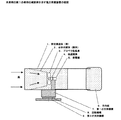
本発明の第1の発明の実施例を図1に示す。図1において、筒状構造体(筒)1は、中空の筒で、実施例では、断面を正方形としたが、円形でも、角を丸めた方形でも構わない。台形状錐体(錐体)2は、筒1の断面と同じ形状の底面をもち、天面が円形である中空の錐体である。錐体2で、風を絞り込み、風速の増幅を行う。底面の面積と、天面の面積比で増幅度は決まるが、増幅度には限界がある。風を絞り込む角度が急であると、風が錐体2に入らず外に逃げてしまうためである。また、錐体2の天面に外部の風が回り込んだりするためである。筒1により、錐体2の天面に風が回り込むのを防いでいる。本実施例では、絞り込み面積を3分の1とした。風車3は、錐体2の天面の円の直径と概略同じ直径のもので、錐体2で増幅された風を受けてそのエネルギーを回転力に変える。伝達機構4は、風車3の回転数を、増速するか、減速するか、または同じ回転数で、発電機5に伝達する。増速、減速または等速で伝達するのは、風車の回転数と発電機の回転数を整合するためである。方向板6は、回転機構8により、筒1の前面を風上の方向に向ける。第1の支持機構7は、筒1,伝達機構4,発電機5を支持する機構である。指示機構7は回転機構8を介して第2の支持機構9の支持を受ける。第2の支持機構は、風力発電装置が設置される台に取り付けられる。
【0016】
本発明の第2の発明の実施例を図2に示す。図2において、筒1から第2の支持機構9までは同じもので、説明を省略する。扉10は、開閉軸12を中心に回転して、筒1の前面の実質開口面積を減らすことができる。開閉用歯車11は、開閉駆動モーター13の駆動により扉10を回転させる。図示を省略したが、発電機5からの電力出力15を監視して出力を上げるまたは下げる要求を検出する仕組みからの出力制御入力16を受け、開閉制御駆動部14が開閉駆動モーター13を駆動する。扉10は、風の抵抗を減らすため丸形流線型としている。強風時には、発電機が高速回転して電力出力が許容限度に近くなる。これを電力出力15を監視する外部の仕組みが検出して、出力制御入力16に出力を下げるように要求が来る。開閉制御駆動部16は、扉10を閉める方向に駆動する。扉10により強風時にも安定した発電をすることができる。このことで、扉10により風車3,発電機5の防御も行われることになる。
【0017】
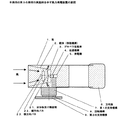
本発明の第3の発明の実施例を図3に示す。図3おいて、筒1の断面を正方形とし、錐体2の形状が異なる以外は、図1に示した本発明第1の発明の実施例と同じである。錐体2を、4枚の台形板で構成し、台形板の底辺を蝶番で筒1の前面または断面の1辺にとりつけ、4枚の台形板が、台形状錐体を構成する第1の位置から、筒1に接する第2の位置まで、移動可能な機構としている。台形板の移動範囲を決めるための、台形板受け構造物21と、縦方向バネ22,横方向バネ23により、通常状態では、台形板が錐体を構成するようにしている。強風時には、風圧により台形板は、筒1に接する方向に移動する。図には明示していないが、移動を安定にするために縦方向バネ22の中央および横方向バネの中央が、台形板受け構造物21に支持され、各バネには、オイルダンプ機構を含んでいる。錐体2が、強風時には筒1に接するように移動して風を筒抜けとし、風による力を減少させるように移動することで、風力発電装置の軽量化を図り、民家の屋根などへの設置を可能としている。風車3、発電機5も、風の増幅度が低くなるため防御される。
【発明の効果】
本発明により、都市に吹く弱い風でも発電することができる。
【0018】
発明の効果を数字で示すため、次の計算をする。増幅せずに、効率が理想風車の70%の受風面積が3m2の風車による1年間の風車出力と、3m2の面積の風を3倍の風速に増幅して、理想風車の70%の受風面積が1m2の風車による1年間の風車出力を、ある都市の風速データにより計算する。受風面積3m2の風車で増幅無しの場合1年間の風車出力は363,189wh、受風面積3m2、風車の受風面積1m2で3.0倍増幅ありの場合、1年間の風車出力は3,260,382whとなり、同じ受風面積3m2でも増幅することにより9倍の出力が得られる。(「小型風車ハンドブック」牛山・三野共著、パワー社を参照した計算。)なおこの値は計算上の値である。風車の効率はもっと悪く、機械損失や発電機の効率も考慮すると、実際の発電電力は計算値より少なくなる。
【図面の簡単な説明】
【図1】本発明の第1の発明の実施例を示す風力発電装置の姿図。
【図2】本発明の第2の発明の実施例を示す風力発電装置の姿図。
【図3】本発明の第3の発明の実施例を示す風力発電装置の姿図。
【符号の説明】
1 筒状構造体
2 台形状錐体
3 プロペラ型風車
4 伝達機構
5 発電機
6 方向板
7 第1の支持機構
8 回転機構
9 第2の支持機構
10 扉
11 開閉用歯車
12 開閉軸
13 開閉駆動モーター
14 開閉制御駆動部
15 電力出力
16 出力制御入力
21 台形板受け構造物
22 縦方向バネ
23 横方向バネTECHNICAL FIELD OF THE INVENTION
[0001]
The present invention relates to a wind power generator.
[Prior art]
[0002]
Wind power generation is widely used in various places. Mainly, large-scale wind power generators were installed in areas where strong wind power was obtained, and large-scale technology was developed to obtain large power. However, little technology has been developed to generate electricity with low wind speeds.
[0003]
The energy per second of the wind is represented by the following equation.
(Equation 1)
ρAV 3 ÷ 2 (1)
Here, ρ: density of air, A: wind receiving area, V: wind speed (second speed). This equation represents the energy of the moving body.
mV 2 ÷ 2 (2)
The volume of air received by the air receiving area A per second is the product of A and V, and its weight m is given by ρ is the density of air.
[Equation 3]
m = ρAV (3)
Thus, it can be obtained by substituting ρAV into m in equation (2). The energy that the area A receives in one second is proportional to the area A and proportional to the cube of the wind speed V. Since the larger the wind speed, the larger the energy that can be obtained in proportion to the third power, the large wind turbine is designed so that a predetermined output can be obtained at a high wind speed, and it is often considered that energy is used at a low wind speed. Absent.
[Problems to be solved by the invention]
[0004]
The present invention solves the technical problems of effective use of low wind speed, control in strong winds, and self-protection in strongest winds, for a wind power generator installed in a city with little wind power.
[0005]
Usually, strong winds are not blowing in cities. In an actual measurement example in a certain city, a wind of 1 m to 10 m per second blows at an average wind speed of 1 hour throughout the year, and there are many winds near 2 m per second. A wind of 10m or more blows in a gust of wind, but only a few hours a year on average. However, the annual maximum wind speed is 32.9m, and strong winds blow gusts. At Cape Muroto, the average hourly wind speed is 4 m / s to 22 m / h, with 6 m / s being the most frequent. It is different from the measured wind speed in the city. The actual measurement example is one city, but in many other cities, except for the building style, there is little impression that a strong wind blows, but it seems to be close to the example of this city. In the example of this city, if the effective use of the low wind speed is designed and the function corresponding to the strong wind is taken into consideration, the city can be operated without any problem in the windy city. According to this actual measurement example, it is important to consider that a wind power generator installed in a city effectively uses energy of a low wind speed of about 2 m, which frequently occurs. Conversely, when the low wind speed is used effectively, at a high wind speed, the windmill rotates at a high speed, and it is necessary to control the wind turbine so that the wind speed is equal to or less than a maximum rotation speed defined as a steady operation range. In some cases, it may be necessary to control power generation depending on conditions such as the storage battery, which is a load on the windmill, is fully charged. Further, since a very strong wind blows in a gust, it is necessary to take measures to prevent the wind power generator from being destroyed by the gust.
Means for Solving the Invention
[0006]
In the wind turbine generator of the present invention, the part of the invention for effectively utilizing the wind energy of low wind speed is a cylinder and a cone attached to the inner surface of the cylinder and having a top surface close to a circle. The wind taken in from the front of the cylinder is narrowed down by a cone, and the wind speed increases as much as the narrowed down. This means that the wind speed has been amplified. In addition, by covering the cone with a cylinder, the deterioration of the performance of wind speed amplification due to wind wraparound is reduced. The amplification g of the wind speed is calculated as
(Equation 4)
g = (area of bottom of cone) ÷ (area of top of cone) (4)
Given by However, when the angle of embedding by the trapezoidal cone is steep or the amplification is large, the wind wraps around and the actual value of the amplification g becomes smaller than the calculated value. If the angle of the cone is loosened to make it a long cone, the cylinder is also long enough to prevent wraparound, especially if the trapezoidal weight is used in the reverse direction on the exit side of the cylinder to gradually reduce the wind speed , The amplification degree close to the calculated value. However, the wind power generator is an object having a large shape, and it is not preferable to make the wind power generator too long from the viewpoint of protecting against a strong wind. The present invention aims to amplify the wind of 2 m / sec, which frequently occurs in the city of the actual measurement example, to 5 m so that power can be generated. In the example, the area of the bottom surface of the cone is 3.0 m 2 , the area of the top surface is 1 m 2 , the narrowed area is one third, and the calculated amplification is 3.0.
[0007]
W1 is the energy of the wind when a wind of 2 m / sec is received in an area of 3.0 m 2 , the wind speed is tripled to 6 m / sec as a calculated value, and the wind is received in an area of 1.0 m 2 Let W2 be the energy of
W1 = ρAV 3 ÷ 2 = ρ × 3 × 2 × 2 × 2 ÷ 2 = 12ρ
(Equation 6)
W2 = ρAV 3 ÷ 2 = ρ × 1 × 6 × 6 × 6 ÷ 2 = 108ρ
The wind energy W2 as the calculated value is nine times as large as W1.
[0008]
Although wind energy is converted into rotational energy by a windmill, it has been found that even with an ideal windmill, only about 50% of the energy of the wind can be used. In addition, the efficiency of an actual windmill is about 70% that of an ideal windmill. When a wind turbine with a wind speed of 2 m is received by a wind turbine having a wind receiving area of 3.0 m 2 , the output of the wind turbine is calculated to be about 6 W (watt). Similarly, when a wind having a wind speed of 5 m is received by a wind turbine having a wind receiving area of 1.0 m 2 , the output of the wind turbine is calculated to be about 31.8 W. ("Small windmill handbook" by Ushiyama and Mino Power Company) In fact, in winds with a wind speed of about 2 m, the output of the windmill is almost 0 W at the limit where the windmill starts to rotate due to loss of friction and the like. The windmill starts rotating at a wind speed of 2 m or more, and the output of the windmill can be obtained. In conclusion, amplification of wind speed is an important requirement in order to utilize the wind with a wind speed of 2 m, which occurs most frequently in cities, for power generation. Although large structures such as cylinders and cones are required, the advantage of using a wind at a wind speed of 2 m is great.
[0009]
It has already been described that the wind power generation device of the present invention amplifies and uses a wind having a wind speed of 2 m by the wind speed amplification mechanism. Since this amplification mechanism is effective even when the wind speed is high, it is necessary to control the output of the windmill. For example, when the wind speed is 20 m, the wind of the windmill becomes a storm with a wind speed of 50 m. In order to control the amplification of the wind speed, in the present invention, a door is provided on the front surface of the cylinder, and the opening of the door is controlled to control the amplification of the wind speed. When the door is completely closed, the amplification degree can be set to zero. In addition, if the shape of the door is a streamline type, the force due to the wind can be reduced. Although the control of the opening of the door may be a simple one utilizing the wind speed, it is desirable to control the opening of the door according to the demand for the output of the generator. If the battery, which is a load on the generator, is fully charged and cannot be charged any more, the door may be closed to stop power generation. Further, during a storm, by controlling the output of the generator, the door is substantially closed, and abnormal high-speed rotation of the generator can be prevented. If a wind speed amplification mechanism is provided, a mechanism for controlling the amplification degree is also desired.
[0010]
Large structures, such as cylinders, cones, and front doors, must be robust enough to withstand storms. In addition, the supporting mechanism for supporting these structures and the rotating supporting mechanism must be ruggedly manufactured. However, since these structures are simple structures, they are not so expensive just because they are ruggedly manufactured.
[0011]
The wind power generator of the present invention is intended to be installed in a city, and is also installed on the roof of a private house. In this case, it is desirable to reduce the weight as much as possible. By making a large-sized structure resistant to the wind, strength can be reduced and weight can be reduced. In one embodiment, the cross section of the tube is square. The cone is composed of four trapezoidal plates. The bottom of each trapezoidal plate is hinged to each side of the front of the tube. A position where the oblique sides of the four trapezoidal plates are in contact with each other is a first limit position, a position where the trapezoidal plate is in contact with the tubular structure is a second limit position, and the trapezoidal plate is in the first limit position and the second limit position. Can be moved between the limit positions. At the first limit position, a structure that stops moving is installed so that the trapezoidal plate does not move any further. The trapezoidal plate is normally at the first limit position by a spring. The trapezoidal plate is configured to move to the second limit position when strongly pressed by wind pressure or the like. When the four trapezoidal plates are at the first limit position, they constitute a cone. However, since the top surface of the weight is square and not circular, a gap is formed between the weight and the windmill. Even if there is a gap, this is not a major problem in operation, but the trapezoidal plate may be deformed so that the upper side of the trapezoidal plate forms a quarter of a circle and the four pieces form a circle. . When the wind speed is equal to or higher than a predetermined wind speed, the trapezoidal plate moves by wind pressure to reduce wind resistance. The trapezoidal plate comes into contact with the inner surface of the cylinder due to the wind pressure, and the amplification of the wind speed is reduced. In this method, the amplification of the wind speed cannot be reduced to 1 or less, but since the wind passes through the cylinder, the force by which the wind pushes the cone can be reduced. In addition, the movement of the trapezoidal plate makes the amplification of the wind speed nearly one-fold, thereby protecting the windmill. However, the degree of amplification cannot be controlled to less than one time, and the windmill must be designed to withstand high-speed rotation under strong winds or a brake mechanism that does not allow high-speed rotation. Although the method of controlling the movement of the trapezoid plate by wind pressure has been described as an example, as another example, a movement control mechanism may be provided to accurately control the movement.
DETAILED DESCRIPTION OF THE INVENTION
Hereinafter, embodiments of the present invention will be described.
[0012]
According to a first aspect of the present invention, there is provided a cylinder, a cone having a bottom surface having the same shape as the cross section of the cylinder, and a top surface having a shape close to a circle having an area smaller than the bottom surface, and a contact with the top surface of the cone. A windmill having a diameter substantially the same as the diameter of the circle, a generator for generating electric power, a transmission mechanism connected to the windmill and transmitting rotation to the generator without changing or changing the rotation speed of the windmill; and A direction plate that directs the front surface of the tube toward the windward direction, a first support mechanism that supports the tube, the transmission mechanism, the generator, and the direction plate, and a mode in which the first support mechanism can be rotated. A wind power generator having a structure in which a bottom surface of the cone is attached to a front surface or a cross section of the cylinder, and the windmill is located near a top surface of the cone. It is a cone-shaped structure that amplifies the speed of the wind to generate power. In order to ensure the degree of amplification of the wind, the tube reduces the amount of wind that wraps around the top of the cone. In this wind power generator, it is necessary that the generator and the supporting mechanism have a sufficient design even in a strong wind.
[0013]
According to a second aspect of the present invention, there is provided a mechanism which is attached to a front face or a first support mechanism and covers the front face according to a request for controlling an output of a generator, thereby enabling an effective opening area of the front face to be changed. The wind turbine generator according to the first aspect of the present invention is provided with the door of the first invention. In the case of a strong wind, the generator rotates at a high speed and the amount of power generation exceeds a predetermined value, and the output of the generator is controlled. Is a request to reduce the amount of power generation. According to this requirement, the front surface of the cylinder, which is the entrance of the wind, is covered with a required amount by a door to prevent the generator from rotating at a higher speed than a predetermined speed. The opening and closing of the door is controlled by a motor. The door is round and streamlined to minimize wind resistance. The wind power generator of the present embodiment needs to be ruggedly manufactured so that a large structure such as a tube can withstand strong wind.
[0014]
In a third aspect of the present invention, the cross section of the cylinder is a polygon, and the cone is formed of a trapezoidal plate having the same number of sides as the polygon, and the bottom side of the trapezoidal plate is a front side or one side of the cross section of the cylinder. A second trapezoidal plate attached to the inner surface of the cylinder, wherein the trapezoidal plate is in contact with the inner surface of the cylinder from a first position where the oblique sides of adjacent trapezoidal plates contact each other to form a cone with the base attached to the cylinder as the center. The wind power generator according to the first aspect of the present invention has a structure that can be moved to the position of the wind power generator according to the first invention, which is intended to reduce the weight of the wind power generator having the wind speed amplifying function and to install it on the roof of a private house. Things. The parts that are mainly subjected to wind force are cones and windmills. Although a proposal has been made to reduce the force exerted on the wind turbine by making the blades of the wind turbine variable, for example, the wind turbine of the present invention is of a small size. In the case of the present invention, it is the cone that reduces the wind by one third that receives the force of the wind. This cone was composed of four trapezoidal plates, and the cross section of the cylinder to which it was attached was also square. When the wind is strong, the trapezoidal plate is opened so as to be in contact with the cylinder by the wind pressure to reduce the wind force. When the strong wind stops, the spring returns to the cone shape. According to the above-described mechanism, only the windmill can receive wind power in a strong wind, so that the strength of a large structure can be reduced and the weight can be reduced.
【Example】
Embodiments of the present invention will be described with reference to the drawings.
[0015]
FIG. 1 shows an embodiment of the first invention of the present invention. In FIG. 1, a tubular structure (tube) 1 is a hollow tube and has a square cross section in the embodiment, but may have a circular shape or a square shape with rounded corners. The trapezoidal cone (pyramid) 2 is a hollow cone having a bottom surface having the same shape as the cross section of the cylinder 1 and a circular top surface. The cone 2 narrows the wind and amplifies the wind speed. The amplification factor is determined by the ratio of the area of the bottom surface to the area ratio of the top surface, but the amplification factor is limited. This is because if the angle at which the wind is narrowed down is steep, the wind will escape to the outside without entering the cone 2. In addition, this is because an external wind may flow around the top surface of the cone 2. The cylinder 1 prevents the wind from flowing around the top surface of the cone 2. In this embodiment, the narrowed area is set to one third. The windmill 3 has substantially the same diameter as the diameter of the circle on the top surface of the cone 2, receives the wind amplified by the cone 2, and converts its energy into rotational force. The transmission mechanism 4 transmits the rotation speed of the wind turbine 3 to the generator 5 by increasing or decreasing the speed, or at the same rotation speed. The transmission at the increased speed, the decelerated speed, or the constant speed is for matching the rotation speed of the windmill with the rotation speed of the generator. The direction plate 6 turns the front surface of the cylinder 1 to the windward direction by the rotation mechanism 8. The first support mechanism 7 is a mechanism that supports the cylinder 1, the transmission mechanism 4, and the generator 5. The instruction mechanism 7 is supported by the second support mechanism 9 via the rotation mechanism 8. The second support mechanism is attached to a table on which the wind turbine generator is installed.
[0016]
FIG. 2 shows an embodiment of the second invention of the present invention. In FIG. 2, the components from the cylinder 1 to the second support mechanism 9 are the same, and the description is omitted. The door 10 can be rotated about the opening / closing axis 12 to reduce the substantial opening area of the front surface of the cylinder 1. The opening / closing gear 11 rotates the door 10 by driving the opening / closing drive motor 13. Although not shown, the power output 15 from the generator 5 is monitored to receive an output control input 16 from a mechanism for detecting a request to increase or decrease the output, and the open / close control drive unit 14 drives the open / close drive motor 13. . The door 10 has a round streamline shape to reduce wind resistance. In strong winds, the generator rotates at high speed and the power output approaches the allowable limit. An external mechanism for monitoring the power output 15 detects this, and a request comes to the output control input 16 to reduce the output. The opening / closing control drive unit 16 drives the door 10 in the closing direction. The door 10 enables stable power generation even in strong winds. Thus, the door 10 also protects the windmill 3 and the generator 5.
[0017]
FIG. 3 shows an embodiment of the third invention of the present invention. 3 is the same as the embodiment of the first invention of the present invention shown in FIG. 1 except that the cross section of the cylinder 1 is square and the shape of the cone 2 is different. The cone 2 is composed of four trapezoidal plates, and the bottom of the trapezoidal plate is hinged to the front surface or one side of the cross section of the cylinder 1, and the four trapezoidal plates constitute a trapezoidal cone. The mechanism is movable from a position to a second position in contact with the cylinder 1. In a normal state, the trapezoidal plate forms a cone in a normal state by a trapezoidal plate receiving structure 21 for determining a moving range of the trapezoidal plate, and a vertical spring 22 and a horizontal spring 23. At the time of strong wind, the trapezoidal plate moves in the direction in contact with the cylinder 1 by wind pressure. Although not shown in the drawing, the center of the vertical spring 22 and the center of the horizontal spring are supported by the trapezoidal plate receiving structure 21 to stabilize the movement, and each spring includes an oil dump mechanism. In. When the cone 2 moves in strong winds, it moves so as to come into contact with the cylinder 1 to remove the wind, and moves so as to reduce the force of the wind, thereby reducing the weight of the wind power generator and installing it on the roof of a private house. Is possible. The windmill 3 and the generator 5 are also protected because the degree of amplification of the wind is reduced.
【The invention's effect】
According to the present invention, it is possible to generate power even in a weak wind blowing over a city.
[0018]
The following calculation is made to show the effect of the invention by numbers. Without amplification efficiency amplifies the wind turbine output of 1 year by 70% windmill wind-receiving area of 3m 2 of the ideal wind turbine, the wind area of 3m 2 to 3 times the wind speed, 70% of the ideal wind turbine The wind turbine output of one year by a wind turbine having a wind receiving area of 1 m 2 is calculated from wind speed data of a certain city. Swept wind turbine output for one year no amplification windmill area 3m 2 is 363,189Wh, swept area 3m 2, case with 3.0 fold amplification in swept area 1 m 2 of the wind turbine, the one-year wind turbine output Is 3,260,382 wh, and a 9-fold output can be obtained by amplifying even the same wind receiving area of 3 m 2 . (Calculation with reference to "Small Windmill Handbook" by Ushiyama and Mino, Power Inc.) This value is a calculated value. The efficiency of a windmill is worse, and the actual generated power is less than the calculated value, taking into account mechanical losses and generator efficiency.
[Brief description of the drawings]
FIG. 1 is a view of a wind turbine generator according to a first embodiment of the present invention.
FIG. 2 is a perspective view of a wind turbine generator according to a second embodiment of the present invention.
FIG. 3 is a view showing a wind turbine generator according to a third embodiment of the present invention.
[Explanation of symbols]
REFERENCE SIGNS LIST 1 tubular structure 2 trapezoidal cone 3 propeller type windmill 4 transmission mechanism 5 generator 6 direction plate 7 first support mechanism 8 rotation mechanism 9 second support mechanism 10 door 11 opening / closing gear 12 opening / closing shaft 13 opening / closing drive Motor 14 Open / close control drive unit 15 Power output 16 Output control input 21 Trapezoidal plate receiving structure 22 Vertical spring 23 Horizontal spring