JP2004100986A - Condenser with straghtening device - Google Patents
Condenser with straghtening device Download PDFInfo
- Publication number
- JP2004100986A JP2004100986A JP2002260045A JP2002260045A JP2004100986A JP 2004100986 A JP2004100986 A JP 2004100986A JP 2002260045 A JP2002260045 A JP 2002260045A JP 2002260045 A JP2002260045 A JP 2002260045A JP 2004100986 A JP2004100986 A JP 2004100986A
- Authority
- JP
- Japan
- Prior art keywords
- condenser
- steam
- rectifier
- heat transfer
- flow
- Prior art date
- Legal status (The legal status is an assumption and is not a legal conclusion. Google has not performed a legal analysis and makes no representation as to the accuracy of the status listed.)
- Pending
Links
- 238000010586 diagram Methods 0.000 description 5
- 238000001816 cooling Methods 0.000 description 3
- 230000007423 decrease Effects 0.000 description 3
- 230000005764 inhibitory process Effects 0.000 description 2
- 238000011144 upstream manufacturing Methods 0.000 description 2
- 230000000694 effects Effects 0.000 description 1
- 230000003628 erosive effect Effects 0.000 description 1
- 238000002955 isolation Methods 0.000 description 1
- 239000007788 liquid Substances 0.000 description 1
- 239000000463 material Substances 0.000 description 1
- 230000002093 peripheral effect Effects 0.000 description 1
- XLYOFNOQVPJJNP-UHFFFAOYSA-N water Substances O XLYOFNOQVPJJNP-UHFFFAOYSA-N 0.000 description 1
- 238000003466 welding Methods 0.000 description 1
Images


Landscapes
- Engine Equipment That Uses Special Cycles (AREA)
Abstract
Description
【0001】
【発明の属する技術分野】
本発明は、高温の蒸気を多数の伝熱管との間で熱交換させて冷却し復水にして回収する復水器に関し、特に、復水器内に流入する蒸気流に含まれる旋回成分を除去して均一流入とするための整流装置に関する。
【0002】
【従来の技術】
例えば、蒸気タービンのタービン車室で仕事を成した高温の蒸気は、排気室から排出されて復水器に流入する。そして、この復水器内部において、蒸気は多数の伝熱管との間で熱交換を行い、冷却されて復水となり回収される。
【0003】
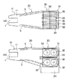
図7は、従来の蒸気タービン用復水器に流入する蒸気の流れを示す概要図であり、(A)は、その上面図、(B)は、その正面図である。この図を参照するに、タービン車室(図示せず)の排気室10は、タービン軸1の軸線方向で且つ蒸気の流れ方向下流に中間胴20へ連接しており、さらにこの中間胴20は、復水器30へと連接している。
【0004】
復水器30は、箱型の胴体31を備えており、胴体31の内部には、多数の伝熱管からなる伝熱管巣32が、複数の伝熱管支持板33に支持されている。伝熱管巣32は、鉛直方向に上下2段、並びに蒸気の流れ方向に前後2段と、分割して設けられている。なお、伝熱管巣32の下方には、復水だめ34が設けられている。
【0005】
このように構成された蒸気タービン用復水器への蒸気の流れを説明する。タービン車室で仕事を成した高温の蒸気の流れSは、排気室10の排気口11から中間胴20の内部を介して復水器30へ流入する。復水器30の内部へ流入した高温の蒸気Sは、各伝熱管巣32の内部に導かれて個々の伝熱管との間で熱交換を行い、冷却されて復水となる。復水は、伝熱管巣32の下方の復水だめ34に集められ、復水出口(図示せず)から回収される。
【0006】
ここで、復水器の性能を良くするためには、タービンの与えられた負荷運転において、高温の蒸気と伝熱管巣との間で良好な伝熱を行わせることが望ましい。そのために、中間胴20を抜けた高温の蒸気は、復水器30の蒸気流入部において一様な流れになることが望まれる。すなわち、復水器30の蒸気流入部で蒸気の流れが一様になれば、蒸気は、上下、前後に分割された伝熱管巣32へ均等に分散し、その結果、個々の伝熱管へ均等に導かれて、両者の間で良好な熱交換が行われるからである。
【0007】
一方、復水器冷却管群の上部に位置する復水器本体の胴部壁面に設けられた連絡胴によって複数の復水器が連結された復水装置において、復水器冷却管群を凝縮した液滴による浸蝕から防止するために、連絡胴の両開口部に整流板をあるいは開口部側の底板の端部に堰を設け、タービン排気蒸気が連絡胴の底板に衝突して発生した液滴が復水器冷却管群へ飛散することを防止するものがある(例えば、特許文献1参照)。
【0008】
【特許文献1】
特開平5−66094号公報(要約、図1及び図2)
【0009】
【発明が解決しようとする課題】
しかしながら、復水器に流入する蒸気には、タービンの回転によって生じる旋回成分が含まれており、流入蒸気のボリュームフローが少ない場合(タービン部分負荷運転時)には、旋回成分が復水器内の蒸気流動の偏りを発生させる原因となる。すなわち、図7に示すように、排気室10の排気口11から流出した蒸気の流れSは、中間胴20の壁面21付近に寄った偏流となる。このような蒸気流動の偏りは、伝熱管への蒸気の供給量に分布を発生させ、復水器内に圧力分布が生じる。この圧力分布が生じると、圧力の低い部分の飽和温度が低下して、見かけ上、伝熱面積が減少するようになり、復水器の伝熱性能が低下して、効率が悪くなるという問題点があった。
【0010】
また、特許文献1に開示された整流板は、連絡胴の底板と平行に複数枚設置されており、旋回成分による蒸気流動の偏りを復水器の蒸気流入部において一様にすることは全くできないものであった。
【0011】
本発明は、このような問題点を解決するためになされたもので、タービンの排気室等から流出する蒸気の流れを復水器の蒸気流入部において一様とし、各伝熱管巣内へ均等に分散して流入できるようにすることにより、性能が向上するような整流装置付復水器を提供することを目的とする。
【0012】
【課題を解決するための手段】
上記目的を達成するために、本発明による整流装置付復水器は、蒸気が流入する蒸気流入部を備えると共に内部に多数の伝熱管からなる伝熱管巣を有する復水器において、前記蒸気流入部の内壁面に、該蒸気流入部を介して流入する蒸気の流れ方向を横切るように内向きに延在するように配設された整流装置を備えることを特徴とする。
【0013】
前記整流装置は、前記蒸気流入部の前記内壁面に沿って環状に配設されているのが好ましく、例えば、オリフィス状部材、案内羽根状部材、オリフィス状の多孔部材であるのが望ましい。また、前記整流装置を、前記蒸気の流れ方向を横切るように前記蒸気流入部の全体に亘って配設することもでき、例えば、ハニカム、多孔板、ワイヤメッシュにすることができる。
【0014】
本発明が適用される装置としては、蒸気タービン用の復水器が好適であり、特に、蒸気タービンと復水器との間に配設された中間胴に前記整流装置を配設するのが好ましい。
【0015】
【作用】
整流装置によって復水器内へ流入する蒸気の流れの旋回成分を緩和して、復水器内の伝熱管巣方向への蒸気流動の偏りを防止することにより、蒸気が伝熱管巣に向けて均等に導かれるようになり、局所的な伝熱疎阻害領域を排除することができる。従って、タービン部分負荷運転時において排気室から排出された蒸気が壁面付近に寄った偏流となっている場合にも、この蒸気は伝熱管巣に向けて均等に導かれるようになる。このようにして、復水器の性能を確保することができる。
【0016】
【発明の実施の形態】
以下に添付の図面を参照しながら本発明の実施の形態を詳述するが、一連の図面において、同一の参照符号は、同様な構成要素を示す。
【0017】
[第一の実施の形態]
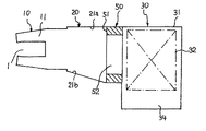
以下、図1を参照しながら本発明の実施の形態を詳述する。図1は、本発明に係る整流装置の第一の実施の形態を示す概要図であり、この図において再度基本的な構成を説明すると、タービン車室(図示せず)の排気室10は、タービン軸1の軸線方向で且つ蒸気の流れ方向下流に中間胴20へ連接しており、さらにこの中間胴20は、復水器30に連接している。
【0018】
復水器30は、箱型の胴体31を備えており、胴体31の内部には、多数の伝熱管からなる伝熱管巣32が複数の伝熱管支持板(図示せず)に支持されている。この伝熱管巣32は、高温の蒸気を流入し易くしてその蒸気との伝熱性能を高めるために、鉛直方向並びに蒸気の流れ方向に各々分割して設けられている。なお、伝熱管巣32の下方には、復水だめ34が設けられている。
【0019】
中間胴20は、上壁面21a、下壁面21b、並びに一対の左右壁面(図示せず)から構成されており、これらの壁面は、その上流側でタービン排気室と、その下流側で復水器30の胴体31と連接している。このような中間胴20は、胴体31と別個に形成しても、胴体31と一体に形成してもよい。
【0020】
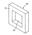
復水器30の内部に配設された伝熱管巣32に向かって蒸気を流入させる蒸気流入部には、本願発明に係る流入する蒸気の旋回成分を緩和して伝熱管巣32への蒸気流動の偏りを防止するための整流装置50が取り付けられている。詳細には、整流装置50は、伝熱管巣32の上流側で中間胴20の出口位置付近の上壁面21a、下壁面21b及び一対の左右壁面からなる内壁面に沿って環状に取り付けられている。この実施形態における整流装置50は、図2から良く分かるように、オリフィス型をしており、環状の板状部51と中央開口52とからなる。なお、整流装置50の形状は、中間胴20あるいは復水器30の内壁面の形状に合わせればよく、この実施形態のように矩形でも、円形でも、如何なる形状にすることもできる。
【0021】
次に、このようなオリフィス型の整流装置50を取り付けた復水器30への蒸気の流れを説明する。タービンの排気室10の排気口11から排出され、旋回成分を含む高流速の蒸気の流れは、中間胴20の内壁面側に偏った流れとなる。しかしながら、壁面側の大きい流れは、整流装置50の板状部51に衝突してから中央開口52を通過するため、整流装置50によって旋回成分が緩和され、蒸気流動の偏りがなくなり均一な流れとなって、伝熱管巣32へ向かって復水器30の内部へ流入する。このように均等な流れになると、圧力分布が小さくなり、局所的な伝熱阻害領域を排除することができる。伝熱管巣32の内部へ導かれた蒸気流は、伝熱管との間で熱交換をして冷却され復水となり、下側に配設された復水だめ34に集められ、図示しない復水出口から回収される。
【0022】
このような整流装置50の作用により、中間胴20の壁面付近に偏った蒸気流は、伝熱管巣32の内部へ均等に導かれるため、伝熱管との間で良好な熱交換を行うことができ、復水器の性能の向上を図ることができる。これにより、特に、排気室10からの蒸気の流れSが壁面付近に寄った偏流となり易いタービン部分負荷運転時における復水器性能が向上するが、定格点での運転時にも、復水器性能の向上を図ることができる。なお、タービンからの高速の蒸気流が整流装置50の板状部51に衝突すると圧力損失が生じるが、全体として圧力分布が一様になるため、結果として復水器30の性能を確保することができる。
【0023】
[第二の実施の形態]
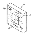
次に、図3を参照しながら本発明の第二の実施の形態を詳述する。なお、復水器30等の基本的構成は、図1に示した第一の実施の形態と同様であるので、説明を省略する。この図において、整流装置60は、第一の実施形態の整流装置50とほぼ同一の形状であるが、板状部が多数の小孔を備えた多孔板61になっている点で相違する。また、多数の小孔を備えた多孔板61を用いているために、衝突する蒸気流に対する圧力損失が単なる板状部より小さくなるので、多孔板61を内壁面からより長く中心側まで延在させることができ、そのため、中央開口62は、第一の実施形態の中央開口52に比して小さくすることができる。これにより、多孔板オリフィス型の整流装置60は、第一の実施形態の単なるオリフィス型の整流装置50に比して、整流能力が高くなる。すなわち、第一の実施の形態よりも、タービン部分負荷運転時及び定各点運転時においての復水器性能をより向上することができる。
【0024】
[第三の実施の形態]
次に、図4を参照しながら本発明の第三の実施の形態を詳述する。なお、この実施形態においても、復水器30等の基本的構成は、図1に示した第一の実施の形態と同様であるので、説明を省略する。この図において、整流装置70は、案内羽根の形状をしており、詳述すると、外周部から内向きに、蒸気の流れ方向に沿って湾曲する案内羽根部71を備えており、その中心側に中央開口72が設けられている。この第三の実施形態によれば、衝突する蒸気流を湾曲する案内羽根部71によって中央開口72に導くため、先の実施形態に比して、より圧力損失を小さくすることができる。
【0025】
[第四の実施の形態]
以上においては、タービン等の高流速用に利用できる整流装置を説明してきたが、以下には、一般的に流速の遅い場合に利用できるような整流装置を説明する。例えば、図5及び図6に示すように、整流装置80を蒸気流入部の全体に亘って配設する。この実施形態では、整流装置80は、多孔板81からなっており、先の実施形態と異なり、中央開口が設けられていない。このように、蒸気流入口全体に亘って配設される整流装置80は、蒸気の流速が速い場合には、圧力損失が大きすぎて使用することができないが、流速の遅い場合には、全体として整流作用が向上するため、安定した復水器30の性能を確保することができる。なお、蒸気流入口全体に亘って配設される整流装置80としては、例えば、ハニカム内臓型にしたり、あるいはワイヤメッシュ型にすることもできる。
【0026】
以上の総ての実施の形態において、整流装置の各壁面への取付は、ボルト止めや溶接など如何なる既知の手段も用いることができる。また、整流装置と各壁面とを一体成形してもよい。また、整流装置は、如何なる材料から成形することもできるが、高温の蒸気と接触するため、耐熱性を有することが好ましい。
【0027】
また、第一の実施形態について触れたが、各整流装置の形状は、中間胴あるいは復水器の内壁面の形状に合わせればよく、これらの実施形態のように矩形に限定されるものでなく、円形でも、多角形でも、如何なる形状にすることもできる。
【0028】
【発明の効果】
本発明による蒸気タービン用復水器は、蒸気流入部の内壁面に、該蒸気流入部を介して流入する蒸気の流れ方向を横切るように内向きに延在するように配設された整流装置を備えているため、復水器内へ流入する蒸気の流れの旋回成分を緩和して、復水器内の伝熱管巣方向への蒸気流動の偏りを防止することができ、蒸気が伝熱管巣に向けて均等に導かれるようになり、局所的な伝熱疎阻害領域を排除して、タービン部分負荷運転時において排気室から排出された蒸気が壁面付近に寄った偏流となっている場合でも、この蒸気の流れが伝熱管巣に向けて均等に導かれるようになり、伝熱管との間で良好な熱交換を行い、復水器性能が向上する。
【図面の簡単な説明】
【図1】本発明に係る整流装置付復水器の形態を示す概要図である。
【図2】図1に示した整流装置の一の実施の形態を示す概要図である。
【図3】整流装置の別の実施の形態を示す概要図である。
【図4】整流装置のさらに別の実施の形態を示す概要図である。
【図5】本発明に係る整流装置付復水器の別の形態を示す概要図である。
【図6】図5に示した整流装置の一の実施の形態を示す概要図である。
【図7】従来の蒸気タービン用復水器に流入する蒸気の流れを示す概要図であり、(A)は、その上面図、(B)は、その正面図である。
【符号の説明】
1…タービン軸、10…排気室、11…排気口、20…中間胴、21…壁面、21a…上壁面、21b…下壁面、30…復水器、31…胴体、32…伝熱管巣、33…伝熱管支持板、34…復水だめ、50…整流装置、51…板状部、52…中央開口、60…整流装置、61…多孔板、62…中央開口、63…小孔、70…整流装置、71…案内羽根部、72…中央開口、80…整流装置、81…多孔板、S…蒸気の流れ。[0001]
TECHNICAL FIELD OF THE INVENTION
The present invention relates to a condenser for exchanging heat between high-temperature steam and a large number of heat transfer tubes to cool and condense and recover the condensate, and in particular, a swirl component contained in a steam flow flowing into the condenser. The present invention relates to a rectifying device for removing and making a uniform inflow.
[0002]
[Prior art]
For example, high-temperature steam that has performed work in a turbine casing of a steam turbine is discharged from an exhaust chamber and flows into a condenser. Then, inside the condenser, the steam exchanges heat with a number of heat transfer tubes, and is cooled to be condensed and collected.
[0003]
FIGS. 7A and 7B are schematic views showing the flow of steam flowing into a conventional steam turbine condenser, wherein FIG. 7A is a top view thereof and FIG. 7B is a front view thereof. With reference to this figure, an
[0004]
The
[0005]
The flow of steam to the steam turbine condenser configured as described above will be described. The high-temperature steam flow S that has completed the work in the turbine casing flows into the
[0006]
Here, in order to improve the performance of the condenser, it is desirable that good heat transfer be performed between the high-temperature steam and the heat transfer tube nest in a given load operation of the turbine. For this reason, it is desired that the high-temperature steam that has passed through the
[0007]
On the other hand, the condenser cooling pipe group is condensed in the condenser where a plurality of condensers are connected by the connecting cylinder provided on the body wall of the condenser body located above the condenser cooling pipe group. In order to prevent erosion due to the droplets, a flow straightening plate is provided at both openings of the communication cylinder, or weirs are provided at the ends of the bottom plate on the opening side, and the liquid generated by turbine exhaust steam colliding with the bottom plate of the communication cylinder is provided. There is one that prevents the droplet from scattering to the condenser cooling tube group (for example, see Patent Document 1).
[0008]
[Patent Document 1]
JP-A-5-66094 (Abstract, FIGS. 1 and 2)
[0009]
[Problems to be solved by the invention]
However, the steam flowing into the condenser includes a swirl component generated by rotation of the turbine, and when the volume flow of the inflow steam is small (during turbine partial load operation), the swirl component is reduced in the condenser. Causes unevenness of the steam flow. That is, as shown in FIG. 7, the flow S of the steam flowing out from the
[0010]
In addition, a plurality of straightening plates disclosed in Patent Document 1 are installed in parallel with the bottom plate of the communication cylinder, and it is completely impossible to make the bias of the steam flow due to the swirling component uniform in the steam inflow portion of the condenser. It was impossible.
[0011]
The present invention has been made in order to solve such a problem, and makes the flow of steam flowing out of the exhaust chamber of the turbine uniform in the steam inflow portion of the condenser and uniformly in each heat transfer tube nest. It is an object of the present invention to provide a rectifier-equipped condenser with improved performance by allowing the flow to be dispersed and introduced into the condenser.
[0012]
[Means for Solving the Problems]
In order to achieve the above object, a condenser with a rectifier according to the present invention includes a steam inflow portion into which steam flows in and a heat transfer tube nest having a plurality of heat transfer tubes therein. A rectifying device is provided on the inner wall surface of the section so as to extend inward so as to intersect the flow direction of the steam flowing through the steam inflow section.
[0013]
The rectifying device is preferably disposed annularly along the inner wall surface of the steam inflow portion, and is preferably, for example, an orifice-shaped member, a guide vane-shaped member, or an orifice-shaped porous member. Further, the rectifying device may be disposed across the entire steam inflow section so as to cross the flow direction of the steam, and may be, for example, a honeycomb, a perforated plate, or a wire mesh.
[0014]
As a device to which the present invention is applied, a condenser for a steam turbine is preferable. In particular, it is preferable to dispose the rectifying device on an intermediate body disposed between the steam turbine and the condenser. preferable.
[0015]
[Action]
By rectifying the flow components of the steam flowing into the condenser by the rectifier, the steam is directed toward the heat transfer tube nests by preventing the steam flow from biasing toward the heat transfer tube nests in the condenser. The heat is uniformly guided, and the local heat transfer isolation inhibition region can be eliminated. Therefore, even when the steam discharged from the exhaust chamber has a drift near the wall surface during the partial load operation of the turbine, the steam is uniformly guided toward the heat transfer tube nest. Thus, the performance of the condenser can be ensured.
[0016]
BEST MODE FOR CARRYING OUT THE INVENTION
Hereinafter, embodiments of the present invention will be described in detail with reference to the accompanying drawings. In the drawings, the same reference numerals indicate similar components.
[0017]
[First embodiment]
Hereinafter, an embodiment of the present invention will be described in detail with reference to FIG. FIG. 1 is a schematic diagram showing a first embodiment of a rectifier according to the present invention. In FIG. 1, the basic configuration will be described again. An
[0018]
The
[0019]
The
[0020]
The steam inflow portion according to the present invention, which alleviates the swirling component of the inflowing steam and transmits the steam to the heat
[0021]
Next, the flow of steam to the
[0022]
By the operation of the
[0023]
[Second embodiment]
Next, a second embodiment of the present invention will be described in detail with reference to FIG. The basic configuration of the
[0024]
[Third embodiment]
Next, a third embodiment of the present invention will be described in detail with reference to FIG. In this embodiment, the basic configuration of the
[0025]
[Fourth embodiment]
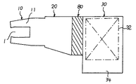
In the above, a rectifying device that can be used for a high flow velocity such as a turbine has been described. Hereinafter, a rectifying device that can be generally used when the flow velocity is low will be described. For example, as shown in FIGS. 5 and 6, the
[0026]
In all of the above embodiments, any known means such as bolting or welding can be used for attaching the rectifier to each wall surface. Further, the rectifier and each wall surface may be integrally formed. Further, the rectifier can be formed from any material, but preferably has heat resistance because it comes into contact with high-temperature steam.
[0027]
Although the first embodiment has been described, the shape of each rectifying device may be adjusted to the shape of the inner wall surface of the intermediate body or the condenser, and is not limited to a rectangular shape as in these embodiments. , A circle, a polygon, or any other shape.
[0028]
【The invention's effect】
A steam turbine condenser according to the present invention is provided with a rectifying device disposed on an inner wall surface of a steam inflow portion so as to extend inward so as to cross a flow direction of steam flowing through the steam inflow portion. Because of this, the swirling component of the flow of steam flowing into the condenser can be reduced, and the bias of the steam flow toward the heat transfer tube nest in the condenser can be prevented. When the steam discharged from the exhaust chamber is drifted near the wall during partial load operation of the turbine by eliminating the area where heat transfer is prevented from being conducted uniformly toward the nest However, this steam flow is evenly directed toward the heat transfer tube nests, thereby performing good heat exchange with the heat transfer tubes and improving the condenser performance.
[Brief description of the drawings]
FIG. 1 is a schematic view showing a condenser with a rectifier according to the present invention.
FIG. 2 is a schematic diagram showing one embodiment of the rectifier shown in FIG.
FIG. 3 is a schematic diagram showing another embodiment of the rectifier.
FIG. 4 is a schematic diagram showing still another embodiment of the rectifier.
FIG. 5 is a schematic view showing another embodiment of the condenser with a rectifier according to the present invention.
FIG. 6 is a schematic view showing one embodiment of the rectifier shown in FIG.
FIG. 7 is a schematic diagram showing a flow of steam flowing into a conventional steam turbine condenser, wherein (A) is a top view thereof and (B) is a front view thereof.
[Explanation of symbols]
DESCRIPTION OF SYMBOLS 1 ... Turbine shaft, 10 ... Exhaust chamber, 11 ... Exhaust port, 20 ... Intermediate body, 21 ... Wall surface, 21a ... Upper wall surface, 21b ... Lower wall surface, 30 ... Condenser, 31 ... Body, 32 ... Heat transfer tube nest, 33 ... heat transfer tube support plate, 34 ... condensate sump, 50 ... rectifier, 51 ... plate-shaped part, 52 ... central opening, 60 ... rectifier, 61 ... perforated plate, 62 ... central opening, 63 ... small hole, 70 ... Rectifier, 71 ... Guiding blade, 72 ... Central opening, 80 ... Rectifier, 81 ... Perforated plate, S: Steam flow.
Claims (11)
前記蒸気流入部の内壁面に、該蒸気流入部を介して流入する蒸気の流れ方向を横切るように内向きに延在するように配設された整流装置を備える整流装置付復水器。In a condenser having a steam inflow portion into which steam flows in and having a heat transfer tube nest composed of a number of heat transfer tubes inside,
A condenser with a rectifying device, comprising: a rectifying device disposed on an inner wall surface of the steam inflow portion so as to extend inward so as to cross a flow direction of steam flowing through the steam inflow portion.
Priority Applications (1)
| Application Number | Priority Date | Filing Date | Title |
|---|---|---|---|
| JP2002260045A JP2004100986A (en) | 2002-09-05 | 2002-09-05 | Condenser with straghtening device |
Applications Claiming Priority (1)
| Application Number | Priority Date | Filing Date | Title |
|---|---|---|---|
| JP2002260045A JP2004100986A (en) | 2002-09-05 | 2002-09-05 | Condenser with straghtening device |
Publications (1)
| Publication Number | Publication Date |
|---|---|
| JP2004100986A true JP2004100986A (en) | 2004-04-02 |
Family
ID=32260874
Family Applications (1)
| Application Number | Title | Priority Date | Filing Date |
|---|---|---|---|
| JP2002260045A Pending JP2004100986A (en) | 2002-09-05 | 2002-09-05 | Condenser with straghtening device |
Country Status (1)
| Country | Link |
|---|---|
| JP (1) | JP2004100986A (en) |
Cited By (2)
| Publication number | Priority date | Publication date | Assignee | Title |
|---|---|---|---|---|
| JP2007178101A (en) * | 2005-12-28 | 2007-07-12 | Mitsubishi Heavy Ind Ltd | Condenser |
| JP2015096802A (en) * | 2015-01-08 | 2015-05-21 | 三菱日立パワーシステムズ株式会社 | Condenser |
-
2002
- 2002-09-05 JP JP2002260045A patent/JP2004100986A/en active Pending
Cited By (2)
| Publication number | Priority date | Publication date | Assignee | Title |
|---|---|---|---|---|
| JP2007178101A (en) * | 2005-12-28 | 2007-07-12 | Mitsubishi Heavy Ind Ltd | Condenser |
| JP2015096802A (en) * | 2015-01-08 | 2015-05-21 | 三菱日立パワーシステムズ株式会社 | Condenser |
Similar Documents
| Publication | Publication Date | Title |
|---|---|---|
| KR100659421B1 (en) | Moisture separator | |
| RO108538B1 (en) | Process and plant for substance exchange between liquid and gaseous mediums | |
| US7544043B2 (en) | Turbulator on the underside of a turbine blade tip turn and related method | |
| US7245689B2 (en) | Nuclear reactor internal structure | |
| CA2214826C (en) | Gas turbine stationary blade | |
| JP2004522049A (en) | Turbine blades including cooling air deflectors | |
| DE60116922D1 (en) | capacitor | |
| JP6302395B2 (en) | Header plateless heat exchanger | |
| CZ200142A3 (en) | The closed circuit of the steam cooling of the turbine rim and the method of steam cooling of the turbine rim | |
| JPH09222284A (en) | Condenser | |
| JP4230841B2 (en) | Condenser | |
| JP2014020723A (en) | Downward flow liquid film type evaporator | |
| JP3907894B2 (en) | Condenser | |
| JP7002420B2 (en) | Direct contact condenser and power plant | |
| JP2000227286A (en) | Condenser | |
| JP5303925B2 (en) | boiler | |
| JP2003028977A (en) | Moisture separator and steam generator | |
| RU2411437C2 (en) | Fan cooling tower | |
| JP3851732B2 (en) | Spray condenser | |
| JP2012112590A (en) | Steam generator, and nuclear power plant | |
| TWI861763B (en) | Flow conditioning device for steam generator and method for increasing hydraulic resistance | |
| KR200237735Y1 (en) | A body heat exchanger of condensing gas boiler | |
| JPH08226776A (en) | Condenser and power plant | |
| JPH09257211A (en) | Water heater | |
| JP2003004387A (en) | Condenser for steam turbine |
Legal Events
| Date | Code | Title | Description |
|---|---|---|---|
| A621 | Written request for application examination |
Free format text: JAPANESE INTERMEDIATE CODE: A621 Effective date: 20040319 |
|
| A977 | Report on retrieval |
Effective date: 20050928 Free format text: JAPANESE INTERMEDIATE CODE: A971007 |
|
| A131 | Notification of reasons for refusal |
Free format text: JAPANESE INTERMEDIATE CODE: A131 Effective date: 20060314 |
|
| A521 | Written amendment |
Free format text: JAPANESE INTERMEDIATE CODE: A523 Effective date: 20060424 |
|
| A02 | Decision of refusal |
Free format text: JAPANESE INTERMEDIATE CODE: A02 Effective date: 20060523 |