【0001】
【発明の属する技術分野】
本発明は、外光の照射条件に依らず常に良好な表示が可能な液晶表示装置に関する。
【0002】
【従来の技術】
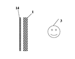
従来の外光を利用する液晶表示装置で、もっとも一般的なのは、図8に示すような反射型液晶表示装置である。これは液晶パネル1の裏面側に拡散反射層14を設けた構造をしている。この反射型液晶表示装置では、観察者3の反対側から入射される外光は拡散反射層14で遮断され利用できず、観察者3側から入射される光しか利用することができない。
【0003】
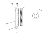
また、完全な反射層の代わりにスリットを設けた反射層や半透過の反射層を用い、図9に示すように、拡散半透過層15として裏面からのバックライトの光を補助的に利用する半透過型液晶表示装置も知られている。この場合も、バックライトの導光板7の裏面に設けられた反射層16により、観察者3の反対側からの外光を利用することはできない。
【0004】
さらに、透過型の液晶表示装置の上端部を開閉可能として、外光を取り入れる機能を持たせたデジタルカメラが販売されたことがあった。これも上端部方向から入射される外光を利用するだけであり、液晶表示装置の背後より入射される多くの外光を利用することはできないので効率が悪い欠点を有している。
【0005】
また、反射層もバックライトも持たない液晶パネルのみで表示をする装置が市販されている。この場合、背後の景色に対して黒表示をする使い方となり、背景の状態により見え方が大きく変わるという問題がある。また、観察者側からの光は利用できないという問題を有している。
【0006】
【発明が解決しようとする課題】
本発明は、上述したような従来技術の問題点を解決し、あらゆる方向からの外光を有効に利用し、明るくコントラストの高い良好な表示を実現する液晶表示装置を提供することを目的とする。
【0007】
【課題を解決するための手段】
上記目的を達成するため、本発明は、液晶層を挟持した一対の基板の外側に一対の偏光板を配置してなる液晶パネルとそれを固定する固定手段とを有する液晶表示装置において、上記液晶パネルの反観察者側に拡散層が配置され、上記固定手段の上記拡散層に対向する面に相当する部分の少なくとも一部が透光性とされ、上記拡散層の反液晶パネル側の面に外光が入り込む構造とされていることを特徴としている。
【0008】
本発明の好ましい態様として、上記拡散層の反液晶パネル側に拡散層に入射する光源が配置されていてもよいし、上記拡散層の反液晶パネル側に透明樹脂層を配置し、この透明樹脂層の側部に光源を配置し、この光源から上記透明樹脂層に導入された光が透明樹脂層内部を全反射を繰り返して導光される間に、該透明樹脂層の表面または内部に設けられた全反射条件を破る拡散機能により拡散層側に出射するようにされていてもよい。
【0009】
いずれの場合においても、上記拡散層の前方散乱量と後方散乱量の割合が、
0.95≧(後方散乱量)/(前方散乱量+後方散乱量)≧0.05
であることが好ましい。
【0010】
【発明の実施の形態】
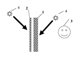
つぎに、図1ないし図7により、本発明の実施形態について説明する。まず、図1において、液晶パネル1の観察者3と反対側に拡散層2が配置され、固定手段(図示せず)の拡散層2に対向する面に相当する部分の透光性部分から、拡散層2の反液晶パネル1側の面に外光4が入り込む構造とされている。
【0011】
ここで、固定手段の拡散層2に対向する面に相当する部分の少なくとも一部を透光性にする方法としては、特に限定されず、固定手段として枠体を用い、拡散層2の背面が外部に露出するようにさせたり、固定手段として筐体を用い、その拡散層2に対向する面の少なくとも一部を透明材料で形成させたり、開口させたり、あるいは透光性の織布もしくは網で形成させる等種々の方法が採用可能である。
【0012】
本発明の液晶表示装置を車載用の表示装置として、図4に示すようなダッシュボード上に載置するセンターメーターやETC表示用等の表示体として使用する場合には、液晶パネルと拡散層との積層体を剥き出しにすれば、運転席側からの光とフロントガラスの外からの光の両方を利用することが可能となって、視認性の高い表示が達成されるとともに、従来の同用途向けの表示装置では外光による表面反射等により表示が見えなくならないように、遮光フードを設けていたがその必要も無くなって、開放感溢れる表示が可能となる。
【0013】
また、本発明の液晶表示装置を電子機器に組み込む場合には、上記筐体全体を透明材料で形成させて、電子機器をスケルトン構造にすれば背部からの外光利用が可能となる。
【0014】
外光を利用する場合ばかりではなく、夜間の使用を考えると、照明できるようにしておくことが好ましい。図1に示した液晶表示装置では、観察者側および反観察者側のいずれから照明光を入れてもよいが、見映えの点で、表面反射の影響を受けにくい反観察者側から照明する方が望ましい。
【0015】
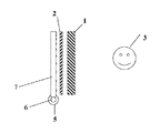
この場合、照明部材により外光の利用が妨げられ無いように工夫することが必要で、スポット的な照明としてもよいが、図2に示すような照明を用いれば、液晶表示装置と一体にすることができ、コンパクトな構造とすることができるので好ましい。
【0016】
図2において、透明樹脂層の側部に配置された光源6から透明樹脂層である導光板7に入射された光は全反射を繰り返して導光していく。導光板7の表面に施された白色網点印刷、または凹凸形状処理、あるいは導光板7に混入された異屈折材料の存在により全反射条件は破られ、拡散層2側に光は出射される。出射された光は拡散層2と液晶パネル1を通過し、観察者3に到達する。ここで、導光板7の背面には反射層が配置されていないので、導光板7は光を透過することができ、反観察者側からの外光も利用できるとともに、照明としても利用することができる。
【0017】
導光板7の表面処理法としては、白色網点印刷では後方散乱量が多いので、光利用効率の面から凹凸形状処理の方が望ましい。導光板を表面処理して拡散性を持たせることにより、導光板に拡散層2の機能を持たせ、拡散層2を省略させることも可能である。この場合は、拡散層が導光板として機能したと見ることができる。導光板の厚みとしては、0.5mmから10mm程度が照明の機能として、また軽量化の観点から適している。
【0018】
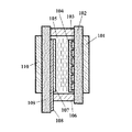
本発明に用いられる液晶パネルの構造を図3に例示する。基板(ガラスまたは透明樹脂等)102,109はそれぞれ、パターニングされた透明電極(ITOなど)103,108、ラビングされた配向膜104,107、シール材106を介して重ね合わされ、液晶層105を挟持している。基板の両側には偏光板101,110が配置されている。
【0019】
液晶モードとしては、TNモード、STNモード、ECBモード、垂直配向モード、インプレーンモードなどがある。図3には図示していないが位相差板、視野角拡大フイルム、拡散板等を用いる場合もある。電圧無印加時に、透明(ノーマリーホワイトモード)か、遮光(ノーマリーブラックモード)かはどちらでもよい。用途、デザインにより適宜選択すればよい。
【0020】
液晶パネル形状も、四角形に限らず、円形や楕円形であってもよく、角にRを付けたり等してもよい。液晶パネル形状と、拡散層の形状は一致していても部分的に違っていてもよい。液晶パネルの駆動としては、スタティック駆動、マルチプレックス駆動、アクティブ駆動のどれを用いてもよい。また、液晶パネルとしては、カラーフイルターを用いたカラー液晶パネルであってもよい。
【0021】
拡散層は一般に前方散乱と後方散乱を有する。図5に示すように、光が拡散層のある面側より垂直に入射し、別の面側より出射する光が前方散乱11とされ、同じ面側より出射する光が後方散乱10とされている。入射光に対して前方散乱される光の量を前方散乱量、後方散乱される量を後方散乱量とする。
【0022】
本発明で用いる拡散層には、後方散乱の機能と、前方散乱の機能の両方が求められる。図1において観察者3とは反対側より液晶表示装置に光が入射される場合、拡散層2には前方散乱の機能が必要であり、後方散乱の機能は必要無い。しかしながら、観察者3側より液晶表示装置に光が入射される場合、拡散層2は後方散乱の機能が必要である。つまりこの場合は反射に相当する機能としての後方散乱が必要となるのである。
【0023】
様々な方向から入射される光を利用するためには、前方散乱量と後方散乱量が最適な拡散層を選択する必要がある。また用途に応じて最適な選択をする必要がある。観察者側からの光を利用する機会が多い場合は、拡散層の後方散乱量を増やす必要があり、また、同ように観察者とは反対側からの光を利用する機会が多い場合は、前方散乱量を増やす必要がある。
【0024】
本発明においては、
0.95≧(後方散乱量)/(前方散乱量+後方散乱量)≧0.05を満足する拡散層を用いることが好ましい。
【0025】
拡散層の種類には、エンボスタイプ、樹脂ビーズタイプ、白色印刷タイプ等がある。エンボスタイプは、表面に凹凸があり凹凸面で光が屈折し拡散する。樹脂ビーズタイプは、樹脂の屈折率に対して異なる屈折率を有するビーズを樹脂中に分散させた構造で、樹脂とビーズ界面で光が屈折し拡散する。また、白色印刷タイプは、樹脂の表面に白色印刷を施すものである。
【0026】
本発明においては、これらのどのタイプ拡散層を用いてもよく、また、併用も可能である。なお、白色印刷による場合には他の方法に比べて前方散乱量が少なくなるが、塗布膜厚を薄くするとか、部分的に施すとかすればよい。液晶パネルと拡散層の相互の配置は平行に限らず斜めでもよく、観察者と液晶パネルの延長線上に拡散層が有ればよい。
【0027】
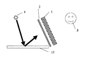
外光の利用効率を高めるために、拡散層の背後に光路変更部材を配置してもよい。例えば、図6に示すような三角プリズムシート12は、入射光の光路を観察者側に変更させる機能を有している。また、図7に示すように拡散層の背後に、白色反射板13、反射層等を配置し、外光の利用効率を高めてもよい。
【0028】
【実施例】
〔例1〕
図1に示す基本構成を有する液晶表示装置を作成した。まず、液晶パネル1は図3の基本構成を有するもので、以下のようにして作成した。パターンニングしたITO透明電極103,108とラビングした配向膜104,107を有する一対のガラス基板102,109を、シール材106とスペーサー(図示せず)を介して貼り合わせ、液晶を真空注入して液晶層105とした。液晶層105は90度ツイストのTNとした。一対の偏光板をガラス基板の外側にそれぞれ配置し、相近接する液晶の長軸方向(屈折率が高い方向)と偏光板の吸収軸方向が同じとなるように配置した。モードとしては、電圧が印加されていない場合に白となるポジモード(ノーマリーホワイトモード)とした。 また、拡散層2としては、樹脂中に樹脂と屈折率が異なる粒子が入った構造を有し、(後方散乱量)/(前方散乱量+後方散乱量)の値が0.2のものを使用した。
【0029】
このようにして得られた液晶表示装置を、図4に示すように車のダッシュボード上に載置すると、フロントガラスより入射される光により、非常に明るい表示を得ることができた。さらに、運転者の背後から光が来た場合も、ウオッシュアウトすることなく良好な表示を視認することができ、ETCの表示部として用いた場合も明るく視認性の高い表示を実現できた。また、図4に示すように液晶表示装置の角にRを付けることによりデザイン性が増した。
【0030】
上記のような車載用途においては、衝突時等に乗員が搭載機器の端面や、破断面で被傷しないようにする必要が有るが、表示装置の周縁に透明樹脂製の枠体を設けたり、表示装置全体を透明樹脂筐体で囲う等により、表示特性を損なわずに安全性を増加できることを確認した。
【0031】
また、図7に示すように背景に白色反射板13を置くと、外光の取り込み効率が上がり明るい表示が可能となった。さらに、本発明の液晶表示装置は傾けて使うと、外光の取り込み効率が低下するが、図6に示すようにプリズム面に対する頂角が上側に非対称構造となっているプリズムシート12を置くことにより外光の取り込み効率が上がり明るい表示が可能となった。
【0032】
〔例2〕
例1と同じ液晶パネルと拡散層を用い、その背後に照明が配置された図2に示す構造の液晶表示装置を作成した。LEDを線状に並べた光源6を用意し、光源6から導光板7に光が入射するように配置する。導光板の厚みは5mmとした。光源6の周りには導光板7に光が入射しやすいように光源反射板5を配置した。導光板7に入った光は全反射を繰り返して導光していく。導光板7の表面は凹凸形状に加工されており全反射条件は破られ、導光板外部に光は出射される。出射された光は拡散層2と液晶パネル1を通過し、観察者に到達する。
【0033】
このようにして得られた液晶表示装置を、例1と同様に車のダッシュボード上に載置する使い方をしたときに、外光が弱い時は、照明により表示を認識することができるようになり、日中も夜も使えて大変便利となった。
【0034】
〔例3〕
例2と同じ構成で、液晶モードとしてTNではなく240°ツイストのSTNを用いた。これにより、高精細表示が可能となり、情報量が増え視認性が上がった。
【0035】
〔例4〕
例3と同じ構成で、RGBのカラーフィルターを組み合わせたカラー表示を実現した。色表示が可能となり格段に情報量が増え視認性が上がった。
【0036】
【発明の効果】
本発明の液晶表示装置は、外光の照射条件に依らず常に良好な表示が可能で、観察者の前方からや背後から光が来ても充分明るく良好な表示を視認することができる。そのため、特に様々な方向より光が入り込む車載用の表示装置として有用である。また、屋外での使用を前提とする携帯用の電子機器、例えば、携帯電話、電子手帳、電子ブック、電子辞書、携帯情報端末(PDA)、ぺージャー、携帯位置検出装置(GPS)、携帯魚群探知機、携帯ゲーム機、などに用いても良好な視認性を発揮する。また、カラーフイルターを組み合わせたカラー表示においても、明るく良好な視認性を発揮する。
【図面の簡単な説明】
【図1】本発明の一実施例の構成を説明する模式的断面図。
【図2】本発明の別の実施例の構成を説明する模式的断面図。
【図3】本発明に用いた液晶パネルの構成を示す模式的断面図。
【図4】本発明を設置する場所を示す模式図。
【図5】拡散層の前方散乱と後方散乱を示す模式図。
【図6】本発明の実施例を説明する模式的断面図。
【図7】本発明の実施例を説明する模式的断面図。
【図8】従来例である反射型液晶表示装置を説明する模式的断面図。
【図9】従来例である半透過型液晶表示装置を説明する模式的断面図。
【符号の説明】
1 液晶パネル
2 拡散層
3 観察者
4 外光
5 光源反射板
6 光源
7 導光板
8 インスツルメントパネル
9 ハンドル
10 後方散乱
11 前方散乱
12 光路変更部材(三角プリズムシート)
13 白色反射板
14 拡散反射層
15 拡散半透過層
16 反射層
101、110 偏光板
102、109 基板
103、108 透明電極
104、107 配向膜
105 液晶層
106 シール材[0001]
BACKGROUND OF THE INVENTION
The present invention relates to a liquid crystal display device capable of always displaying a good image regardless of external light irradiation conditions.
[0002]
[Prior art]
A conventional liquid crystal display device using external light is a reflective liquid crystal display device as shown in FIG. This has a structure in which a diffuse reflection layer 14 is provided on the back side of the liquid crystal panel 1. In this reflective liquid crystal display device, external light incident from the opposite side of the observer 3 is blocked by the diffuse reflection layer 14 and cannot be used, and only light incident from the observer 3 side can be used.
[0003]
In addition, a reflective layer provided with a slit or a semi-transmissive reflective layer is used instead of a complete reflective layer, and the light from the backlight from the back surface is used as an auxiliary as the diffuse semi-transmissive layer 15 as shown in FIG. A transflective liquid crystal display device is also known. Also in this case, external light from the opposite side of the observer 3 cannot be used by the reflective layer 16 provided on the back surface of the light guide plate 7 of the backlight.
[0004]
Furthermore, there has been a case where a digital camera has been sold that can open and close the upper end of a transmissive liquid crystal display device and has a function of taking in external light. This also uses only the external light incident from the direction of the upper end, and cannot use much external light incident from behind the liquid crystal display device.
[0005]
Devices that display only with a liquid crystal panel that does not have a reflective layer or a backlight are commercially available. In this case, the background scenery is displayed in black, and there is a problem that the appearance changes greatly depending on the background state. In addition, there is a problem that light from the observer side cannot be used.
[0006]
[Problems to be solved by the invention]
SUMMARY OF THE INVENTION An object of the present invention is to provide a liquid crystal display device that solves the above-described problems of the prior art, and that effectively uses external light from all directions to realize a bright and high-contrast good display. .
[0007]
[Means for Solving the Problems]
In order to achieve the above object, the present invention provides a liquid crystal display device having a liquid crystal panel in which a pair of polarizing plates are arranged outside a pair of substrates sandwiching a liquid crystal layer, and a fixing means for fixing the liquid crystal panel. A diffusion layer is disposed on the counter-observer side of the panel, and at least a part of the portion corresponding to the surface facing the diffusion layer of the fixing means is translucent, and on the surface of the diffusion layer on the side opposite to the liquid crystal panel It is characterized by a structure that allows external light to enter.
[0008]
As a preferred embodiment of the present invention, a light source incident on the diffusion layer may be disposed on the anti-liquid crystal panel side of the diffusion layer, or a transparent resin layer is disposed on the anti-liquid crystal panel side of the diffusion layer. A light source is disposed on the side of the layer, and the light introduced from the light source into the transparent resin layer is guided on the inside of the transparent resin layer by repeating total reflection and provided on the surface or inside of the transparent resin layer. The light may be emitted to the diffusion layer side by a diffusion function that breaks the total reflection condition.
[0009]
In any case, the ratio of the forward scattering amount and the backward scattering amount of the diffusion layer is
0.95 ≧ (backscattering amount) / (forward scattering amount + backscattering amount) ≧ 0.05
It is preferable that
[0010]
DETAILED DESCRIPTION OF THE INVENTION
Next, an embodiment of the present invention will be described with reference to FIGS. First, in FIG. 1, the diffusion layer 2 is disposed on the opposite side of the liquid crystal panel 1 from the viewer 3, and the translucent portion corresponding to the surface facing the diffusion layer 2 of the fixing means (not shown) External light 4 enters the surface of the diffusion layer 2 on the side opposite to the liquid crystal panel 1.
[0011]
Here, the method of making at least a part of the portion corresponding to the surface of the fixing means facing the diffusion layer 2 translucent is not particularly limited, and a frame is used as the fixing means, and the back surface of the diffusion layer 2 is Exposed to the outside, using a casing as a fixing means, and forming at least a part of a surface facing the diffusion layer 2 with a transparent material, opening, or a translucent woven cloth or net Various methods, such as forming by, can be adopted.
[0012]
When the liquid crystal display device of the present invention is used as an in-vehicle display device as a display body such as a center meter or ETC display placed on a dashboard as shown in FIG. 4, a liquid crystal panel, a diffusion layer, If the laminate is exposed, it is possible to use both the light from the driver's seat side and the light from the outside of the windshield, achieving a highly visible display, In the display device for directing, a shading hood is provided so that the display is not made invisible due to surface reflection by external light, but the necessity is eliminated, and a display full of openness can be realized.
[0013]
In addition, when the liquid crystal display device of the present invention is incorporated in an electronic device, external light from the back can be used by forming the entire casing from a transparent material and making the electronic device a skeleton structure.
[0014]
It is preferable to be able to illuminate when considering use at night as well as when using outside light. In the liquid crystal display device shown in FIG. 1, illumination light may be input from either the observer side or the counter-observer side, but illumination is performed from the counter-observer side that is less susceptible to surface reflection in terms of appearance. Is preferable.
[0015]
In this case, it is necessary to devise so that the use of external light is not hindered by the illumination member, and it may be spot-like illumination, but if illumination as shown in FIG. 2 is used, it is integrated with the liquid crystal display device. This is preferable because a compact structure can be obtained.
[0016]
In FIG. 2, light incident on the light guide plate 7, which is a transparent resin layer, from the light source 6 disposed on the side of the transparent resin layer is guided by repeating total reflection. The total reflection condition is broken by white dot printing applied to the surface of the light guide plate 7 or uneven shape processing, or the presence of a different refractive material mixed in the light guide plate 7, and light is emitted to the diffusion layer 2 side. . The emitted light passes through the diffusion layer 2 and the liquid crystal panel 1 and reaches the observer 3. Here, since the reflective layer is not disposed on the back surface of the light guide plate 7, the light guide plate 7 can transmit light, and can also use external light from the anti-observer side, and can also be used as illumination. Can do.
[0017]
As the surface treatment method of the light guide plate 7, the white dot printing has a large amount of backscattering, so that the uneven shape treatment is more desirable in terms of light utilization efficiency. It is possible to make the light guide plate have the function of the diffusion layer 2 and to omit the diffusion layer 2 by treating the light guide plate with a diffusivity. In this case, it can be considered that the diffusion layer functions as a light guide plate. As the thickness of the light guide plate, about 0.5 mm to 10 mm is suitable as an illumination function and from the viewpoint of weight reduction.
[0018]
The structure of the liquid crystal panel used in the present invention is illustrated in FIG. Substrates (such as glass or transparent resin) 102 and 109 are overlapped via patterned transparent electrodes (such as ITO) 103 and 108, rubbed alignment films 104 and 107, and sealing material 106, and sandwich liquid crystal layer 105. doing. Polarizing plates 101 and 110 are disposed on both sides of the substrate.
[0019]
As the liquid crystal mode, there are a TN mode, an STN mode, an ECB mode, a vertical alignment mode, an in-plane mode, and the like. Although not shown in FIG. 3, a phase difference plate, a viewing angle expansion film, a diffusion plate, or the like may be used. When no voltage is applied, either transparent (normally white mode) or light shielding (normally black mode) may be used. What is necessary is just to select suitably by a use and a design.
[0020]
The shape of the liquid crystal panel is not limited to a quadrangle, and may be a circle or an ellipse, or may have a corner with an R. The shape of the liquid crystal panel and the shape of the diffusion layer may be the same or may be partially different. Any of static drive, multiplex drive, and active drive may be used for driving the liquid crystal panel. In addition, the liquid crystal panel may be a color liquid crystal panel using a color filter.
[0021]
The diffusion layer generally has forward scattering and backscattering. As shown in FIG. 5, light enters perpendicularly from the surface side where the diffusion layer is present, light emitted from another surface side is regarded as forward scattering 11, and light emitted from the same surface side is regarded as backscattering 10. Yes. The amount of light scattered forward with respect to the incident light is defined as a forward scattering amount, and the amount of back scattering is defined as a back scattering amount.
[0022]
The diffusion layer used in the present invention is required to have both a back scattering function and a forward scattering function. In FIG. 1, when light is incident on the liquid crystal display device from the side opposite to the observer 3, the diffusion layer 2 needs a forward scattering function and does not need a back scattering function. However, when light is incident on the liquid crystal display device from the viewer 3 side, the diffusion layer 2 needs to have a backscattering function. That is, in this case, backscattering is necessary as a function corresponding to reflection.
[0023]
In order to use light incident from various directions, it is necessary to select a diffusion layer having an optimum forward scattering amount and backward scattering amount. In addition, it is necessary to make an optimal selection according to the application. When there are many opportunities to use light from the viewer side, it is necessary to increase the backscattering amount of the diffusion layer, and when there are many opportunities to use light from the opposite side of the viewer, The amount of forward scattering needs to be increased.
[0024]
In the present invention,
It is preferable to use a diffusion layer that satisfies 0.95 ≧ (back scattering amount) / (forward scattering amount + back scattering amount) ≧ 0.05.
[0025]
The types of the diffusion layer include an emboss type, a resin bead type, and a white printing type. The embossed type has unevenness on the surface, and light is refracted and diffused on the uneven surface. The resin bead type has a structure in which beads having a refractive index different from the refractive index of the resin are dispersed in the resin, and light is refracted and diffused at the interface between the resin and the beads. The white printing type performs white printing on the surface of the resin.
[0026]
In the present invention, any of these types of diffusion layers may be used, and they can be used in combination. In the case of white printing, the amount of forward scattering is smaller than in other methods, but the coating film thickness may be reduced or partially applied. The mutual arrangement of the liquid crystal panel and the diffusion layer is not limited to being parallel but may be oblique, and it is only necessary that the diffusion layer is on the extension line between the observer and the liquid crystal panel.
[0027]
In order to increase the utilization efficiency of external light, an optical path changing member may be disposed behind the diffusion layer. For example, the triangular prism sheet 12 as shown in FIG. 6 has a function of changing the optical path of incident light to the observer side. In addition, as shown in FIG. 7, a white reflection plate 13, a reflection layer, and the like may be disposed behind the diffusion layer to increase the use efficiency of external light.
[0028]
【Example】
[Example 1]
A liquid crystal display device having the basic configuration shown in FIG. 1 was produced. First, the liquid crystal panel 1 has the basic configuration shown in FIG. 3 and was prepared as follows. A pair of glass substrates 102 and 109 having patterned ITO transparent electrodes 103 and 108 and rubbed alignment films 104 and 107 are bonded together through a sealant 106 and a spacer (not shown), and liquid crystal is injected by vacuum. A liquid crystal layer 105 was obtained. The liquid crystal layer 105 is 90 ° twisted TN. A pair of polarizing plates were arranged on the outside of the glass substrate, respectively, so that the major axis direction (direction in which the refractive index was high) of the liquid crystal adjacent to each other and the absorption axis direction of the polarizing plate were the same. The mode was a positive mode (normally white mode) that turned white when no voltage was applied. The diffusion layer 2 has a structure in which particles having a refractive index different from that of the resin are contained in the resin, and the value of (backscattering amount) / (forward scattering amount + backscattering amount) is 0.2. used.
[0029]
When the liquid crystal display device thus obtained was placed on the dashboard of the car as shown in FIG. 4, a very bright display could be obtained by the light incident from the windshield. Further, even when light comes from behind the driver, a good display can be visually recognized without being washed out, and a bright and highly visible display can be realized even when used as an ETC display unit. In addition, as shown in FIG. 4, the design is improved by adding an R to the corner of the liquid crystal display device.
[0030]
In the in-vehicle application as described above, it is necessary to prevent the occupant from being damaged at the end face of the mounted device or the torn surface at the time of a collision, etc. It was confirmed that safety can be increased without losing display characteristics by enclosing the entire display device with a transparent resin casing.
[0031]
Further, when the white reflector 13 is placed on the background as shown in FIG. 7, the efficiency of taking in external light is increased and a bright display is possible. Further, when the liquid crystal display device of the present invention is used at an angle, the efficiency of taking in external light is lowered. However, as shown in FIG. As a result, the efficiency of capturing external light has increased and a bright display has become possible.
[0032]
[Example 2]
A liquid crystal display device having the structure shown in FIG. 2 was prepared in which the same liquid crystal panel and diffusion layer as in Example 1 were used and illumination was placed behind them. A light source 6 in which LEDs are arranged in a line is prepared, and arranged so that light enters the light guide plate 7 from the light source 6. The thickness of the light guide plate was 5 mm. A light source reflector 5 is arranged around the light source 6 so that light can easily enter the light guide plate 7. The light that enters the light guide plate 7 is guided by repeating total reflection. The surface of the light guide plate 7 is processed into an uneven shape, the total reflection condition is broken, and light is emitted outside the light guide plate. The emitted light passes through the diffusion layer 2 and the liquid crystal panel 1 and reaches the observer.
[0033]
When the liquid crystal display device thus obtained is placed on the dashboard of a car in the same manner as in Example 1, the display can be recognized by illumination when the external light is weak. It became very convenient to use during the day and at night.
[0034]
[Example 3]
In the same configuration as in Example 2, STN having 240 ° twist was used instead of TN as the liquid crystal mode. As a result, high-definition display is possible, the amount of information is increased, and visibility is improved.
[0035]
[Example 4]
With the same configuration as Example 3, color display combining RGB color filters was realized. Color display has become possible, and the amount of information has increased dramatically, improving visibility.
[0036]
【The invention's effect】
The liquid crystal display device of the present invention can always display a good display regardless of the external light irradiation conditions, and can display a sufficiently bright and good display even when light comes from the front or back of the observer. Therefore, it is particularly useful as a vehicle-mounted display device in which light enters from various directions. Also, portable electronic devices that are assumed to be used outdoors, such as mobile phones, electronic notebooks, electronic books, electronic dictionaries, personal digital assistants (PDAs), pagers, portable position detectors (GPS), and portable fish schools Even if it is used for a detector, a portable game machine, etc., it exhibits good visibility. In addition, the color display combined with the color filter exhibits bright and good visibility.
[Brief description of the drawings]
FIG. 1 is a schematic cross-sectional view illustrating a configuration of an embodiment of the present invention.
FIG. 2 is a schematic cross-sectional view illustrating the configuration of another embodiment of the present invention.
FIG. 3 is a schematic cross-sectional view showing a configuration of a liquid crystal panel used in the present invention.
FIG. 4 is a schematic view showing a place where the present invention is installed.
FIG. 5 is a schematic diagram showing forward scattering and back scattering of a diffusion layer.
FIG. 6 is a schematic cross-sectional view illustrating an embodiment of the present invention.
FIG. 7 is a schematic cross-sectional view illustrating an embodiment of the present invention.
FIG. 8 is a schematic cross-sectional view illustrating a conventional reflective liquid crystal display device.
FIG. 9 is a schematic cross-sectional view illustrating a conventional transflective liquid crystal display device.
[Explanation of symbols]
DESCRIPTION OF SYMBOLS 1 Liquid crystal panel 2 Diffusion layer 3 Observer 4 External light 5 Light source reflective plate 6 Light source 7 Light guide plate 8 Instrument panel 9 Handle 10 Back scattering 11 Forward scattering 12 Optical path changing member (triangular prism sheet)
13 White reflector 14 Diffuse reflective layer 15 Diffuse semi-transmissive layer 16 Reflective layer 101, 110 Polarizing plate 102, 109 Substrate 103, 108 Transparent electrode 104, 107 Alignment film 105 Liquid crystal layer 106 Sealing material