JP2004102995A - Super-power-saving type meter - Google Patents
Super-power-saving type meter Download PDFInfo
- Publication number
- JP2004102995A JP2004102995A JP2003208400A JP2003208400A JP2004102995A JP 2004102995 A JP2004102995 A JP 2004102995A JP 2003208400 A JP2003208400 A JP 2003208400A JP 2003208400 A JP2003208400 A JP 2003208400A JP 2004102995 A JP2004102995 A JP 2004102995A
- Authority
- JP
- Japan
- Prior art keywords
- pointer
- magnet
- link member
- switch
- power
- Prior art date
- Legal status (The legal status is an assumption and is not a legal conclusion. Google has not performed a legal analysis and makes no representation as to the accuracy of the status listed.)
- Pending
Links
- 238000005259 measurement Methods 0.000 claims abstract description 7
- 238000005303 weighing Methods 0.000 claims description 35
- 230000001105 regulatory effect Effects 0.000 claims description 8
- 230000003993 interaction Effects 0.000 claims description 3
- 230000000149 penetrating effect Effects 0.000 claims description 3
- 230000002093 peripheral effect Effects 0.000 claims description 3
- 230000001960 triggered effect Effects 0.000 claims description 3
- 238000001514 detection method Methods 0.000 description 10
- 238000000034 method Methods 0.000 description 6
- XLYOFNOQVPJJNP-UHFFFAOYSA-N water Substances O XLYOFNOQVPJJNP-UHFFFAOYSA-N 0.000 description 5
- 238000010586 diagram Methods 0.000 description 4
- 238000005452 bending Methods 0.000 description 2
- 230000007257 malfunction Effects 0.000 description 2
- 238000009825 accumulation Methods 0.000 description 1
- 238000006243 chemical reaction Methods 0.000 description 1
- 238000009826 distribution Methods 0.000 description 1
- 230000000694 effects Effects 0.000 description 1
- 230000005611 electricity Effects 0.000 description 1
- -1 electricity Substances 0.000 description 1
- 239000012530 fluid Substances 0.000 description 1
- 238000009434 installation Methods 0.000 description 1
- 238000004519 manufacturing process Methods 0.000 description 1
- 238000010248 power generation Methods 0.000 description 1
Images


Classifications
-
- G—PHYSICS
- G01—MEASURING; TESTING
- G01F—MEASURING VOLUME, VOLUME FLOW, MASS FLOW OR LIQUID LEVEL; METERING BY VOLUME
- G01F1/00—Measuring the volume flow or mass flow of fluid or fluent solid material wherein the fluid passes through a meter in a continuous flow
- G01F1/05—Measuring the volume flow or mass flow of fluid or fluent solid material wherein the fluid passes through a meter in a continuous flow by using mechanical effects
- G01F1/06—Measuring the volume flow or mass flow of fluid or fluent solid material wherein the fluid passes through a meter in a continuous flow by using mechanical effects using rotating vanes with tangential admission
- G01F1/075—Measuring the volume flow or mass flow of fluid or fluent solid material wherein the fluid passes through a meter in a continuous flow by using mechanical effects using rotating vanes with tangential admission with magnetic or electromagnetic coupling to the indicating device
Landscapes
- Physics & Mathematics (AREA)
- Electromagnetism (AREA)
- Fluid Mechanics (AREA)
- General Physics & Mathematics (AREA)
- Measuring Volume Flow (AREA)
- Details Of Flowmeters (AREA)
- Arrangements For Transmission Of Measured Signals (AREA)
Abstract
Description
【0001】
【発明の属する技術分野】
本発明は、アナログ計量器の測定値をデジタル信号に変換するための計量器に関し、さらに詳細には、アナログ方式の計量器によって計測される測定値が一定量になるときの値を検出してその値をデジタル信号に変換し、その測定値(デジタル信号)を積算計数する遠隔装置に極めて小さい電力で伝送可能にすることによって、計量器設置場所における電力消耗を著しく減らし、動作電源として提供されるバッテリなどを交換することなく長期間使用可能にした超節電型計量器に関する。
【0002】
【従来の技術】
周知の如く、水道、電気、ガスなどは、使用者の使用量を計測・積算し、所定の一定期間になると、それまでに積算された測定値(計測値)を検針して課金している。
【0003】
この課金のためには各使用者の月別使用量を月毎に検針しなければならないが、この検針作業は、検針者が各使用者の使用場所を直接訪問して行われている。
【0004】
しかしながら、このような検針は、使用者の不在または各種犯罪の恐れのため、円滑で正確には行われていないのが実情である。
【0005】
この種の問題を改善するために、各使用者の積算された計測値を遠隔地から検針できる様々な方法が提案されているが、このような多くの遠隔検針方法を実現するためには高コストの設備が必要とされ、実用化の障害となっている。
【0006】
そこで、本出願人は、流量無線検針システム(特許文献1)を先出願したところである。
【0007】
この先出願登録された特許文献1に記載された考案は、検針・計量器の流速に応じて回転する回転軸の上部に置かれる永久磁石と、この永久磁石との相互作用により発電するコイルとを備え、このコイルにより発電された電力を充填して回路電源として利用し、また、発電波形を分析してアナログ−デジタル(A/D)コンバータで流量積算値を検出・積算して遠隔地に伝送するようにした流量無線検針システムである。
【0008】
しかしながら、上記先出願考案は、既存の手作業による検針における人的労力は軽減されたものの、回路構成が複雑で、製造コストが高いという欠点があった。
【0009】
一方、計量器の配設された場所においてその計量器により計測された測定値をデジタル化するための様々な方式が提案されたが、それら提案された方式は、アナログ計測値をデジタル化するための回路構成や、構成された回路の動作電源に大きな制限を有していた。
【0010】
例えば、水道計量器の場合には、通常、電気配線と離れた地下に埋め立てられているために、商用電源の分電盤などに連結することが困難であり、乾電池、蓄電池のようなバッテリ(電源駆動手段)などを使用しなければならなかった。
【0011】
しかしながら、このようにバッテリを使用する場合、従来の各種計量器は電力消耗の激しい構造となっていたために、乾電池などのバッテリを頻繁に交換しなければならず、実用化に至っていないという問題があった。
【0012】
つまり、計量器の計量が止まり、その内部の検出センサが特定ポイントで停止しているとき(使用者の使用中断時)にもこの検出センサが持続的に検出状態となっているため、検出センサと関連した回路による電力消耗が継続され、乾電池などの電力が余分に消耗され、電源供給手段として提供される乾電池などを交換することなく長期間使用することが不可能となっていた。
【0013】
したがって、電源供給手段として利用される乾電池などを採用した計量器は、少なくとも10年ほどは乾電池などを交換することなく継続的(連続的)に使用できないと実用化し難い。
【0014】
【特許文献1】
大韓民国実用新案登録第228613号公報
【0015】
【発明が解決しようとする課題】
本発明は、上記課題に鑑みてなされたものであり、その目的は、公知の計量器に組み合わせてなり、計量器の一回転を一つのデジタル信号として検出するリーダースイッチのセンシング範囲を指針の回転速度に拘わらず迅速に通過できるようにすることによって正確な検出を可能にし、また、短い検出時間のみ電力が消耗されるため、電力消費を著しく減らすことから乾電池などの電源供給手段を交換することなく長期使用を可能にした超節電型計量器を提供することにある。
【0016】
また、本発明の他の目的は、検出センサのリーダースイッチのセンシング範囲を指針の回転速度に拘わらず迅速に通過しながら検出が行われるようにすることによって検出の誤動作を防止した超節電型計量器を提供することにある。
【0017】
【課題を解決するための手段】
上記目的を達成するために、本発明に係る超節電型計量器は、アナログ計量器の測定値をデジタル信号に変換するものであって、使用量に応じて回転する指針の回転中心軸から偏心した位置に磁石を有するリンク部材を該指針とヒンジ結合し、前記リンク部材の磁石との相互作用によって指針の一回転をデジタル信号として生成するセンサとしてリーダースイッチを前記磁石に近接可能な位置に設け、前記リーダースイッチのセンシング範囲から外れた進入位置に前記リンク部材の進入を一時的に規制する規制部を設け、前記規制部で蓄積された規制力を前記リンク部材に一挙にトリガーできるようにし、指針の回転速度に拘わらず前記リンク部材の磁石が前記リーダースイッチのセンシング範囲を迅速に通過しながら計量を行うように構成したことを特徴とする。
【0018】
本発明によれば、前記リンク部材の磁石が前記センサを迅速に通過できるようにしてセンサ作動範囲内に停止することを防止しているので、作動電源は瞬間的な駆動時にのみ制限的に消耗されるようになっている。
【0019】
ここで、本発明の超節電型計量器は、回転する指針と、計量目盛りが表示された固定板とを含めてなる指針部を有し、
前記指針部の指針は、尖った先端の反対面に凹溝と、この凹溝を前記固定板と垂直な方向に貫通するピン孔とを有し、
前記凹溝には、リンク部材として先端に磁石を埋め込まれているリンク軸が前記ピン孔を介して固定ピンによって屈曲可能にヒンジ結合され、
前記指針部の固定板には、前記規制部として前記リンク部材の磁石と対向する面が同一極性を有するように前記センシング範囲への進入位置に配置される第1磁石と、前記リーダースイッチを通過した進出位置には前記第1磁石と逆極性を有する第2磁石とを配置し、
前記固定板に配置する前記第1および第2磁石の略中間位置には、前記リンク部材の磁石と相互作用して計量信号を発生する前記リーダースイッチが設けらるように構成されてもよい。
【0020】
この場合、好ましくは、前記リンク部材の磁石と相互作用する前記第1および第2磁石は、前記リーダースイッチのセンシング可能範囲を外れた地点にそれぞれ配置される。
【0021】
また、本発明の超節電型計量器は、回転する指針と計量目盛りが表示された固定板とを含めてなる指針部を有し、
前記指針は、前記リンク部材と固定ピンによって結合されており、前記指針に対して屈曲可能なリンク軸の端部には磁石が埋め込まれており、
前記リンク軸と前記指針は、前記指針の回転方向には直線状態をなし、前記指針の回転方向と反対の方向には屈曲可能に形成されるものの、屈曲された前記リンク軸を直線状態に復元させるためのばねを前記指針と前記リンク部材との間に設け、
前記固定板の外周側には、センサとして前記リーダースイッチが設けられ、このリーダースイッチへの進入方向には、前記規制部としてストッパが設けられ、
前記リンク部材の端部は、前記指針の回転中前記ストッパに一時的に規制され、前記リンク部材が屈曲されながら回動され、前記ばねの復元力によって前記リンク部材が前記ストッパを乗り越えて前記指針の端部にある磁石が前記リーダースイッチを通過しながら計量を行うように構成されてもよい。
【0022】
【発明の実施の形態】
以下、本発明の好ましい実施形態を添付図面を参照しつつ詳細に説明する。
【0023】
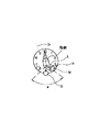
図1に示すように、本発明の超節電型計量器は、使用量に応じて回転する指針の回転中心軸から偏心した位置にヒンジ結合している、磁石Mを有するリンク部材Lと、このリンク部材Lの磁石Mによって指針の一回転をデジタル信号として生成するセンサとして、磁石Mに近接するように配置されたリーダースイッチSと、このリーダースイッチSのセンシング範囲aから外れた進入位置に配置される、リンク部材Lの進入を一時的に規制する規制部hとを備えている。そして、この超節電型計量器は、規制部hで蓄積された規制力がリンク部材Lを一挙にトリガーできるようにすることによって、
指針の回転速度に拘わらずセンサのセンシング範囲aを通過するよう構成されている。
【0024】
ここで、規制部hは、磁石であってもよく、あるいは、機械的なストッパであってもよいが、本発明の一実施形態では、リンク部材Lの磁石との間に作用する斥力と引力を用いる場合、すなわち、規制部hが磁石の場合について説明する。
【0025】
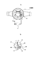
図2は、本発明を水道計量器に適用した一実施形態を示す図である。
【0026】
図2の水道計量器には、通過する流体に基づいてその使用量を表示する表示指針が構成されているが、本発明の好ましい実施のためには、少なくとも最小計量単位(図2では一回転が1トン単位である)が指針の一回転に対応する指針部で具現するのが好ましい。これは、回転速度が相対的に速い一回転をなす最小量指針の回転駆動が最小電力を消耗しながらも正確に検出でき、検出量の積算計量に有用であるためである。
【0027】
図2bに示すように、本発明の計量器は、回転する指針20と、その板上に計量目盛りが表示された固定板12とを有する指針部10を備えている。この指針部10の指針20は、図3aに示すように、尖った先端の反対側に凹溝22と、この凹溝22を貫通するピン孔24とを有する。リンク部材として先端に磁石Mを埋め込まれている(内蔵されている)リンク軸28は、ピン孔24に挿入される固定ピン26によって、この凹溝22内にヒンジ結合されている。
【0028】
また、指針部10の固定板12には、リンク軸28の磁石Mと対向する面が同一極性を有するように、センシング範囲aへの進入位置に磁石M1を規制部として配置しているとともに、センサのリーダースイッチSを回転方向に通過したセンシング範囲a外の位置(進出位置)には磁石Mと対向する面が逆極性を有する磁石M2を配置している。
【0029】
そして、リンク軸28の磁石Mと相互作用して計量信号を発生するリーダースイッチSが固定板12に配置する磁石M1、M2の略中間位置に設けられる。磁石M1、M2は、上述のように、リーダースイッチSのセンシング可能範囲aを外れた地点に配置される。
【0030】
このように構成される本発明の超節電型計量器の作用について説明すると、以下のようである。
【0031】
指針20がその一端(凹溝22側)において回転中心軸から離れた位置に偏心されたリンク軸28にヒンジ結合されているので、このリンク軸28は、指針20の長手方向に対して左右に屈曲しながら指針20上でスイング自在に移動することができる。
【0032】
このとき、リンク軸28の屈曲角度は、凹溝22の両端部に設けられた突部22aによって制限される。
【0033】
図4を参照すれば、使用者の水道の使用によって計量器の指針が計測回転するとき、0.1L単位で一回転する指針の場合には、速く回転することになる。
【0034】
指針が回転する場合、図4(a)に示すように指針20が原点(0)当たりを指している場合、リンク軸28の磁石Mと固定板12上の磁石M2との間には相互引力が作用し、リンク軸28は不動(静止)状態となる。
【0035】
この磁石MとM2の間に生じる引力は、図4(b)および図4(c)に示す状態まで保たれる。その後、指針20が回転し続けて、指針20の凹溝22に設けられた突部22aにリンク軸28の側面が当接する角度までリンク軸28が屈曲されると(図4(c)参照)、磁石相互間に作用する引力は、指針20の回転力、すなわち、指針20の側面から突部22aへの作用力(外力)によって離脱され、指針20は、比較的自由にリンク軸28が屈曲した状態で回転を続ける(図4(d)参照)。
【0036】
指針20がさらに回転し続けて、リンク軸28の磁石MがリーダースイッチS側のセンシング範囲aへの進入直前の位置になると、リンク軸28の磁石Mと固定板12に配置された磁石M1との間には、相互に同一極性を有しているため、斥力が発生する。
【0037】
つまり、それらの磁石M、M1間には斥力が作用して、指針20の一端側にあるリンク軸28の回転は規制される。この規制は、指針20の突部22aにリンク軸28が当接し、それらが一体的に回転される瞬間まで継続される。突部22aに当接して指針20の回転力を受けながら磁石Mが磁石M1の中心部を超える瞬間に、規制されていたリンク軸28は、逆方向への斥力を利用してリーダースイッチSの方向にトリガーさせる作用によって固定ピン26を中心に瞬間的に回転(スイング)するが、このとき、回転(スイング)方向に配置された同一極性の磁石M2の引力も共に作用するため、リンク軸28は、リーダースイッチSのセンシング範囲(センシング区間)aを迅速に離脱することができる。
【0038】
勿論、センシング範囲aを迅速に移動(回転)している間にもリーダースイッチSのセンシング動作は行われ、このセンシング区間におけるリンク軸28の回動は、指針20の回転速度とは無関係に独立して行われる(図4(e)および図4(f)参照)。
【0039】
すなわち、指針20が回転中心軸の周りを一回転する間、リンク軸28もまたリーダースイッチSのセンシング範囲aを一回通過し、また、指針20がある区間でゆっくりと回転したり静止していたりしても、リーダースイッチSと相互作用するリンク軸28の磁石Mは、リーダースイッチSのセンシング範囲a外で待機することが理解されるであろう。
【0040】
このように、本発明の計量器は、リーダースイッチSのセンシング時にのみ電力が消耗されるので、消費電力を著しく減らす(低減する)ことができ、また、指針20が静止している場合には、リーダースイッチSのセンシング範囲a外に磁石Mが位置しているので、リーダースイッチSの余計な(無駄な)連続的動作を排除することができる。その結果、例えば、本実施形態では、センシングのための電力消耗を概ね10〜20μA/hr程度に保つことができ、本発明の計量器に使用する乾電池などの電源供給手段を長期間使用(この場合、約10年)することができる。
【0041】
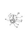
次に、図5を参照して本発明の他の実施形態を説明する。
【0042】
本実施形態は、指針のセンシング範囲内への進入を一時的に制限する規制部が磁石でない機械的なストッパからなり、トリガーのための圧力蓄積をばねで具現化した点にその特徴がある。
つまり、指針20aは、固定ピン56によりリンク部材であるリンク軸58と結合されており、指針20aから屈曲されるリンク軸58の端部には磁石Mが埋め込まれている。リンク軸58は、指針20aの回転方向側には直線状態までしか屈曲できず、通常は、直線状態に保持されているが、指針20aの回転方向と反対の方向には屈曲可能に構成されている。また、屈曲されたリンク軸58を直線状態に復元させるためのばね59が指針20aとリンク軸58との間に設けられている。固定板12の外周側には、センサとしてリーダースイッチSが設けられ、このリーダースイッチSへの進入方向には、ストッパ60が規制部として設けられている。これにより、リンク軸58の端部(図5では、磁石Mの埋設されているところ)が回転中ストッパ60に一時的に規制され、リンク軸58が屈曲回動されるように構成されている。
【0043】
このように構成される本発明の他の実施形態では、センサであるリーダースイッチSのセンシング範囲への進入前にリンク軸58の端部がストッパ60にかかることによりその回転が制限され、リンク軸58が固定ピン56を中心に折り曲げられた状態を保ちながら指針20aが回転する。そして、引き続き指針20aが回転してばね59に所定の圧力以上の力が加わると、その圧力(復元力)によってリンク軸58は、ストッパ60を乗り越えて指針20aと直線状態になると同時に、その先端の磁石MがリーダースイッチSの近くを通過して計量が行われる。
【0044】
本実施形態もまた、指針20aが静止したりゆっくりと回転したりする場合には、センシング範囲外にリンク軸58の磁石Mが位置し、圧縮されたばね59のトリガー(復元力)によって瞬間的にセンシングおよび計量が行われる。
【0045】
その結果、本実施形態の計量器によって、センシングのための電力消耗および誤動作率を著しく低減させることができる。
【0046】
なお、上述の実施形態では説明していない符号Tは、リーダースイッチSのカウンティング信号を処理し、そのカウントされたデジタル信号値を遠隔地に伝送することができるように制御するコントローラを示している。このコントローラTは、そのような技術分野における当業者により容易に具現化され得るので、ここではその説明は省略する。
【0047】
【発明の効果】
以上のように、本発明の超節電型計量器は、公知のアナログ計量器に組み合わせてなるものであって、計量器の一回転を一つのデジタル信号として検出するリーダースイッチのセンシング範囲を指針の回転速度に拘わらず迅速に通過できるように、リーダースイッチと相互作用する磁石をリンク部材部分に構成したため、正確な検出が可能であり、且つ、短い検出時間のみ電力が消耗されるので、計量器の電力消耗を著しく減らすことができる。これにより、本発明は、乾電池などの電源供給手段を交換することなく、10年程度の長期使用が可能なので、別途の電源配線を設けずに済み、地下に埋設された計量器などにも適用し易い。
【0048】
また、本発明は、センサのリーダースイッチのセンシング範囲を指針回転速度に拘わらず迅速に通過するリンク部材の磁石によって検出(計量)するため、検出の誤動作を防止するとともに、リンク部材の磁石がリーダースイッチのセンシング範囲内に止まることを完全に排除することができるため、センサの連続的駆動による電力消耗および回路誤動作や故障などを防止することができる。
【図面の簡単な説明】
【図1】本発明のデジタル信号変換概念を示す概略図。
【図2】本発明の一実施形態における計量器の構造図。
【図3】図2における指針構造による各状態を示す要部抜粋構成図。
【図4】図2における指針部の段階別状態を示す作動状態図。
【図5】本発明の他の実施形態における計量器の構造図。
【符号の説明】
M、M1、M2 磁石
S リーダースイッチ
10 指針部
20、20a 指針
22 凹溝
22a 突部
24 ピン孔
26、56 固定ピン
28、58 リンク軸
59 ばね
60 ストッパ[0001]
TECHNICAL FIELD OF THE INVENTION
The present invention relates to a measuring device for converting a measured value of an analog measuring device into a digital signal, and more particularly, detecting a value when a measured value measured by an analog measuring device becomes a fixed amount. By converting the value into a digital signal and transmitting the measured value (digital signal) to a remote device that accumulates and counts with extremely low power, the power consumption at the scale installation site is significantly reduced, and the measured value (digital signal) is provided as an operating power source. The present invention relates to a super-power-saving weighing device which can be used for a long time without replacing a battery or the like.
[0002]
[Prior art]
As is well known, for water, electricity, gas, and the like, the amount of use of a user is measured and integrated, and when a predetermined period has elapsed, the measured value (measured value) integrated so far is read and charged. .
[0003]
For this billing, the monthly usage amount of each user must be read every month, but this meter reading operation is performed by directly visiting the place of use of each user.
[0004]
However, such meter reading is not performed smoothly and accurately due to the absence of a user or fear of various crimes.
[0005]
In order to solve this kind of problem, various methods have been proposed in which the metered value of each user can be read from a remote place. However, in order to realize such many remote meter reading methods, high methods are required. Costly equipment is required, which is an obstacle to practical application.
[0006]
Therefore, the present applicant has just applied for a flow rate wireless meter reading system (Patent Document 1).
[0007]
The invention described in Patent Document 1 registered in this prior application includes a permanent magnet placed above a rotating shaft that rotates according to the flow rate of a meter / meter, and a coil that generates electric power by interaction with the permanent magnet. The power generated by this coil is charged and used as a circuit power source. The power generation waveform is analyzed, and the integrated flow rate is detected and integrated by an analog-digital (A / D) converter and transmitted to a remote location. This is a flow rate wireless meter reading system.
[0008]
However, the above-described invention of the prior application has a disadvantage that the circuit configuration is complicated and the manufacturing cost is high, although the human labor in the existing manual meter reading is reduced.
[0009]
On the other hand, various methods for digitizing the measured value measured by the measuring device at the place where the measuring device is arranged have been proposed.These proposed methods are for digitizing analog measured values. And the operating power supply of the configured circuit has great limitations.
[0010]
For example, in the case of a water meter, it is usually difficult to connect to a distribution board of a commercial power source because the meter is buried in an underground distant from electric wiring. Power supply driving means).
[0011]
However, when a battery is used in this way, the conventional various measuring instruments have a structure that consumes a great deal of power, so that batteries such as dry batteries must be frequently replaced, and the problem is that the battery has not been put to practical use. there were.
[0012]
In other words, when the weighing of the weighing device is stopped and the detection sensor inside the weighing device stops at a specific point (when the user stops using the device), the detection sensor is continuously detected. However, the power consumption of the dry battery and the like is excessively consumed, and it has been impossible to use the dry battery and the like provided as the power supply means for a long time without replacing the dry battery and the like.
[0013]
Therefore, a measuring instrument employing a dry battery used as a power supply means cannot be put into practical use unless it can be used continuously (continuously) without replacing the dry battery for at least about 10 years.
[0014]
[Patent Document 1]
Republic of Korea Utility Model Registration No. 228613
[Problems to be solved by the invention]
The present invention has been made in view of the above problems, and an object of the present invention is to combine a known weighing instrument with a known weighing instrument, and to set a sensing range of a reader switch for detecting one rotation of the weighing instrument as one digital signal to rotate a pointer. Replacement of power supply means such as dry batteries to enable accurate detection by allowing quick passage regardless of speed and to reduce power consumption because power is consumed only for a short detection time It is an object of the present invention to provide a super-power-saving weighing instrument which can be used for a long time without any problem.
[0016]
Another object of the present invention is to provide a super-power-saving weighing device in which a detection error is prevented by performing detection while rapidly passing through a sensing range of a reader switch of a detection sensor regardless of a rotation speed of a pointer. To provide equipment.
[0017]
[Means for Solving the Problems]
In order to achieve the above object, a super-power-saving weighing device according to the present invention converts a measurement value of an analog weighing device into a digital signal, and is eccentric from a rotation center axis of a pointer that rotates according to a usage amount. A link member having a magnet at a set position is hinged to the pointer, and a reader switch is provided at a position accessible to the magnet as a sensor that generates one rotation of the pointer as a digital signal by interaction with the magnet of the link member. Providing a restricting portion for temporarily restricting the entry of the link member at an entry position out of the sensing range of the reader switch, so that the regulating force accumulated in the regulating portion can be triggered on the link member at once, A configuration in which the magnet of the link member performs weighing while rapidly passing through the sensing range of the reader switch regardless of the rotation speed of the pointer Characterized in that was.
[0018]
According to the present invention, since the magnet of the link member is allowed to quickly pass through the sensor and is prevented from stopping within the sensor operating range, the operating power is limitedly consumed only during an instantaneous drive. It is supposed to be.
[0019]
Here, the super-power-saving weighing device of the present invention has a pointer portion including a rotating pointer and a fixed plate on which a graduation scale is displayed,
The pointer of the pointer portion has a concave groove on the surface opposite to the sharp tip, and a pin hole penetrating the concave groove in a direction perpendicular to the fixing plate,
In the concave groove, a link shaft having a magnet embedded at the tip as a link member is hinged so as to be bendable by a fixing pin through the pin hole,
The fixing plate of the pointer portion passes through the first magnet, which is disposed at the entrance position to the sensing range so that the surface facing the magnet of the link member has the same polarity as the regulating portion, and passes through the reader switch. At the advanced position, the first magnet and a second magnet having the opposite polarity are arranged,
The reader switch which interacts with the magnet of the link member to generate a weighing signal may be provided at a substantially intermediate position between the first and second magnets arranged on the fixed plate.
[0020]
In this case, preferably, the first and second magnets interacting with the magnet of the link member are respectively disposed at points outside the sensing range of the reader switch.
[0021]
Further, the super-power-saving weighing device of the present invention has a pointer portion including a rotating pointer and a fixed plate on which a graduation scale is displayed,
The pointer is coupled to the link member by a fixing pin, and a magnet is embedded at an end of a link shaft that is bendable with respect to the pointer,
The link shaft and the pointer form a linear state in the rotation direction of the pointer, and are formed to be bendable in a direction opposite to the rotation direction of the pointer, but restore the bent link axis to a linear state. A spring is provided between the pointer and the link member,
On the outer peripheral side of the fixed plate, the leader switch is provided as a sensor, and a stopper is provided as the restricting portion in an approach direction to the leader switch,
The end of the link member is temporarily restricted by the stopper during rotation of the pointer, the link member is rotated while being bent, and the link member rides over the stopper by the restoring force of the spring, and the pointer moves. May be configured to measure while passing through the reader switch with the magnet at the end of the.
[0022]
BEST MODE FOR CARRYING OUT THE INVENTION
Hereinafter, preferred embodiments of the present invention will be described in detail with reference to the accompanying drawings.
[0023]
As shown in FIG. 1, the super-power-saving weighing device of the present invention includes a link member L having a magnet M, which is hinged at a position eccentric from a rotation center axis of a pointer that rotates according to the amount of use, and As a sensor for generating one rotation of the pointer as a digital signal by the magnet M of the link member L, a leader switch S arranged so as to be close to the magnet M and an entrance position outside the sensing range a of the leader switch S And a restricting portion h for temporarily restricting the entry of the link member L. The super-power-saving weighing device is configured such that the regulating force accumulated in the regulating portion h can trigger the link member L at once,
It is configured to pass through the sensing range a of the sensor regardless of the rotation speed of the pointer.
[0024]
Here, the restricting portion h may be a magnet or a mechanical stopper, but in one embodiment of the present invention, the repulsive force and the attractive force acting between the link member L and the magnet are provided. Is used, that is, the case where the restricting portion h is a magnet will be described.
[0025]
FIG. 2 is a diagram showing an embodiment in which the present invention is applied to a water meter.
[0026]
The water meter of FIG. 2 is provided with a display indicator for indicating the amount of use based on the fluid passing therethrough. However, for the preferred embodiment of the present invention, at least the minimum metering unit (one rotation in FIG. 2) Is preferably in the unit of one ton). This is because the rotation drive of the minimum amount pointer, which makes one revolution with a relatively high rotation speed, can detect accurately while consuming the minimum power, and is useful for the integrated measurement of the detected amount.
[0027]
As shown in FIG. 2b, the weighing device of the present invention includes a
[0028]
Further, the fixing
[0029]
A leader switch S that generates a weighing signal by interacting with the magnet M of the
[0030]
The operation of the thus configured super-power-saving measuring device of the present invention will be described below.
[0031]
Since the
[0032]
At this time, the bending angle of the
[0033]
Referring to FIG. 4, when the pointer of the measuring instrument rotates by measurement when the user uses the water supply, if the pointer rotates once in units of 0.1 L, the pointer rotates quickly.
[0034]
When the pointer rotates, when the
[0035]
The attractive force generated between the magnets M and M2 is maintained until the state shown in FIGS. 4B and 4C. Thereafter, when the
[0036]
When the
[0037]
That is, a repulsive force acts between the magnets M and M1, and the rotation of the
[0038]
Of course, the sensing operation of the reader switch S is also performed while the sensing range a is quickly moved (rotated), and the rotation of the
[0039]
That is, while the
[0040]
As described above, the measuring device of the present invention consumes power only at the time of sensing the reader switch S, so that the power consumption can be significantly reduced (reduced), and when the
[0041]
Next, another embodiment of the present invention will be described with reference to FIG.
[0042]
This embodiment is characterized in that the restricting portion for temporarily restricting the pointer from entering the sensing range is formed of a mechanical stopper other than a magnet, and the pressure accumulation for the trigger is realized by a spring.
That is, the
[0043]
In another embodiment of the present invention configured as described above, the end of the
[0044]
Also in the present embodiment, when the
[0045]
As a result, the measuring device of the present embodiment can significantly reduce power consumption and malfunction rate for sensing.
[0046]
Reference numeral T, which is not described in the above embodiment, indicates a controller that processes the counting signal of the reader switch S and controls the counted digital signal value to be transmitted to a remote place. . Since the controller T can be easily embodied by those skilled in such technical field, its description is omitted here.
[0047]
【The invention's effect】
As described above, the super-power-saving weighing device of the present invention is a combination of a known analog weighing device, and the sensing range of the reader switch that detects one rotation of the weighing device as one digital signal is used as a pointer. Since a magnet that interacts with the leader switch is formed in the link member so that it can pass quickly regardless of the rotation speed, accurate detection is possible, and power is consumed only for a short detection time. Power consumption can be significantly reduced. As a result, the present invention can be used for a long period of time of about 10 years without replacing the power supply means such as a dry battery, so that there is no need to provide a separate power supply line, and the present invention can be applied to a measuring instrument buried underground. Easy to do.
[0048]
Further, according to the present invention, since the sensing range of the sensor reader switch is detected (measured) by the magnet of the link member that quickly passes regardless of the rotation speed of the pointer, erroneous detection can be prevented, and the magnet of the link member can be detected by the reader. Since it is possible to completely prevent the sensor from staying within the sensing range of the switch, it is possible to prevent power consumption due to continuous driving of the sensor, circuit malfunction, and failure.
[Brief description of the drawings]
FIG. 1 is a schematic diagram illustrating a digital signal conversion concept of the present invention.
FIG. 2 is a structural view of a weighing device according to an embodiment of the present invention.
FIG. 3 is an essential part extracted configuration diagram showing each state by the pointer structure in FIG. 2;
FIG. 4 is an operation state diagram showing a state of each stage of the pointer portion in FIG. 2;
FIG. 5 is a structural view of a weighing device according to another embodiment of the present invention.
[Explanation of symbols]
M, M1, M2 Magnet S Leader switch 10
Claims (4)
使用量に応じて回転する指針の回転中心軸から偏心した位置に磁石を有するリンク部材を該指針とヒンジ結合し、
前記リンク部材の磁石との相互作用によって指針の一回転をデジタル信号として生成するセンサとしてリーダースイッチを前記磁石に近接可能な位置に設け、
前記リーダースイッチのセンシング範囲から外れた進入位置に前記リンク部材の進入を一時的に規制する規制部を設け、
前記規制部で蓄積された規制力を前記リンク部材に一挙にトリガーできるようにし、指針の回転速度に拘わらず前記リンク部材の磁石が前記リーダースイッチのセンシング範囲を迅速に通過しながら計量を行うように構成したことを特徴とする超節電型計量器。A super-power-saving measuring device that converts a measurement value of an analog measuring device into a digital signal,
A link member having a magnet at a position eccentric from the rotation center axis of the pointer that rotates according to the usage amount is hingedly coupled to the pointer,
A reader switch is provided at a position accessible to the magnet as a sensor that generates one rotation of the pointer as a digital signal by interaction with the magnet of the link member,
Providing a restricting portion for temporarily restricting the entry of the link member at an entry position outside the sensing range of the reader switch,
The restricting force accumulated in the restricting portion can be triggered at once by the link member, so that the magnet of the link member performs measurement while quickly passing through the sensing range of the reader switch regardless of the rotation speed of the pointer. A super-power-saving weighing device characterized in that:
前記指針部の指針は、尖った先端の反対面に凹溝と、この凹溝を前記固定板と垂直な方向に貫通するピン孔とを有し、
前記凹溝には、リンク部材として先端に磁石を埋め込まれているリンク軸が前記ピン孔を介して固定ピンによって屈曲可能にヒンジ結合され、
前記指針部の固定板には、前記規制部として前記リンク部材の磁石と対向する面が同一極性を有するように前記センシング範囲への進入位置に配置される第1磁石と、前記リーダースイッチを通過した進出位置には前記第1磁石と逆極性を有する第2磁石とを配置し、
前記固定板に配置する前記第1および第2磁石の略中間位置には、前記リンク部材の磁石と相互作用して計量信号を発生する前記リーダースイッチが設けられている請求項1に記載の超節電型計量器。It has a pointer that includes a rotating pointer and a fixed plate on which a weighing scale is displayed,
The pointer of the pointer portion has a concave groove on the surface opposite to the sharp tip, and a pin hole penetrating the concave groove in a direction perpendicular to the fixing plate,
In the concave groove, a link shaft having a magnet embedded at the tip as a link member is hinged so as to be bendable by a fixing pin through the pin hole,
The fixing plate of the pointer portion passes through the first magnet, which is disposed at the entrance position to the sensing range so that the surface facing the magnet of the link member has the same polarity as the regulating portion, and passes through the reader switch. At the advanced position, the first magnet and a second magnet having a reverse polarity are arranged,
2. The super switch according to claim 1, wherein the leader switch is provided at a substantially intermediate position between the first and second magnets disposed on the fixed plate, the reader switch interacting with the magnet of the link member to generate a weighing signal. A power-saving meter.
前記指針は、前記リンク部材と固定ピンによって結合されており、前記指針に対して屈曲可能なリンク軸の端部には磁石が埋め込まれており、
前記リンク軸と前記指針は、前記指針の回転方向には直線状態をなし、前記指針の回転方向と反対の方向には屈曲可能に形成されるものの、屈曲された前記リンク軸を直線状態に復元させるためのばねを前記指針と前記リンク部材との間に設け、
前記固定板の外周側には、センサとして前記リーダースイッチが設けられ、このリーダースイッチへの進入方向には、前記規制部としてストッパが設けられ、
前記リンク部材の端部は、前記指針の回転中前記ストッパに一時的に規制され、前記リンク部材が屈曲されながら回動され、前記ばねの復元力によって前記リンク部材が前記ストッパを乗り越えて前記指針の端部にある磁石が前記リーダースイッチを通過しながら計量を行うように構成される請求項1に記載の超節電型計量器。It has a pointer part including a rotating pointer and a fixed plate on which a weighing scale is displayed,
The pointer is coupled to the link member by a fixing pin, and a magnet is embedded at an end of a link shaft that is bendable with respect to the pointer,
The link shaft and the pointer form a linear state in the rotation direction of the pointer, and are formed to be bendable in a direction opposite to the rotation direction of the pointer, but restore the bent link axis to a linear state. A spring is provided between the pointer and the link member,
On the outer peripheral side of the fixed plate, the leader switch is provided as a sensor, and a stopper is provided as the restricting portion in an approach direction to the leader switch,
The end of the link member is temporarily restricted by the stopper during rotation of the pointer, the link member is rotated while being bent, and the link member rides over the stopper by the restoring force of the spring, and the pointer moves. The super-power-saving weighing device according to claim 1, wherein a magnet at an end of the weighing device is configured to perform weighing while passing through the reader switch.
Applications Claiming Priority (3)
| Application Number | Priority Date | Filing Date | Title |
|---|---|---|---|
| KR20020053604 | 2002-09-05 | ||
| KR20020071469 | 2002-11-18 | ||
| KR10-2003-0009202A KR100457665B1 (en) | 2002-09-05 | 2003-02-13 | Ultra power-saving type meter for converting measured value into digital signal |
Publications (1)
| Publication Number | Publication Date |
|---|---|
| JP2004102995A true JP2004102995A (en) | 2004-04-02 |
Family
ID=31982167
Family Applications (1)
| Application Number | Title | Priority Date | Filing Date |
|---|---|---|---|
| JP2003208400A Pending JP2004102995A (en) | 2002-09-05 | 2003-08-22 | Super-power-saving type meter |
Country Status (5)
| Country | Link |
|---|---|
| US (1) | US20050046417A1 (en) |
| JP (1) | JP2004102995A (en) |
| CN (1) | CN1480711A (en) |
| AU (1) | AU2003219598A1 (en) |
| WO (1) | WO2004023083A1 (en) |
Cited By (2)
| Publication number | Priority date | Publication date | Assignee | Title |
|---|---|---|---|---|
| JP2013092493A (en) * | 2011-10-27 | 2013-05-16 | Kashiwabara Keiki Kogyo Kk | Hybrid water meter |
| JP2023148860A (en) * | 2022-03-30 | 2023-10-13 | 株式会社Sirc | Detector |
Families Citing this family (7)
| Publication number | Priority date | Publication date | Assignee | Title |
|---|---|---|---|---|
| CN101788314B (en) * | 2010-02-24 | 2011-08-03 | 彭希南 | Wireless tap water meter |
| CN101788316B (en) * | 2010-02-24 | 2011-04-27 | 管于球 | Angular water meter |
| US8656789B2 (en) | 2011-03-08 | 2014-02-25 | Landis+Gyr Innovations, Inc. | Adapter assembly for a utility meter for wirelessly transmitting data |
| US8336407B2 (en) * | 2011-03-08 | 2012-12-25 | Landis+Gyr Innovations, Inc. | Utility meter adapter |
| US8451001B2 (en) * | 2011-08-09 | 2013-05-28 | Landis+Gyr Innovations, Inc. | Utility meter adapter |
| CN111337088B (en) * | 2020-04-16 | 2024-12-20 | 广东捷先智能制造有限公司 | Structure of direct reading counter and mechanical meter with the same |
| CN115684689A (en) * | 2022-08-26 | 2023-02-03 | 国网浙江省电力有限公司海盐县供电公司 | A magnetic induction device for detection of pole-mounted switch state |
Family Cites Families (12)
| Publication number | Priority date | Publication date | Assignee | Title |
|---|---|---|---|---|
| US744407A (en) * | 1903-02-24 | 1903-11-17 | Universal Accountant Machine Company | Counting mechanism. |
| US1699807A (en) * | 1927-11-07 | 1929-01-22 | Westinghouse Electric & Mfg Co | Electrical measuring instrument |
| US2321419A (en) * | 1939-02-20 | 1943-06-08 | Landis & Gyr Ag | Electricity meter |
| US2922111A (en) * | 1956-03-30 | 1960-01-19 | Westinghouse Electric Corp | Coupling mechanism |
| US4728950A (en) * | 1984-04-16 | 1988-03-01 | Telemeter Corporation | Magnetic sensor apparatus for remotely monitoring a utility meter or the like |
| GB9309073D0 (en) * | 1993-05-01 | 1993-06-16 | Dames Andrew N | Resonator orientation sensing |
| JPH0727776A (en) * | 1993-07-08 | 1995-01-31 | Toshiba Corp | Rotation detection method |
| JPH08226932A (en) * | 1995-02-20 | 1996-09-03 | Uno Seisakusho:Kk | Fluid sensor |
| US6229299B1 (en) * | 1998-11-17 | 2001-05-08 | Caterpillar Inc. | System and method for computing the angular velocity and direction of a rotational body |
| JP2001108495A (en) * | 1999-10-07 | 2001-04-20 | Toshiba Meter Techno Kk | Intermittent drive, flow meter |
| CA2455473A1 (en) * | 2001-07-31 | 2003-02-13 | American Express Travel Related Services Company, Inc. | System and method for providing financial planning and advice |
| US7023200B2 (en) * | 2002-06-18 | 2006-04-04 | Siemens Vdo Automotive Corporation | Non-contacting large angle rotary position sensor for rotating shaft |
-
2003
- 2003-04-10 WO PCT/KR2003/000729 patent/WO2004023083A1/en not_active Ceased
- 2003-04-10 AU AU2003219598A patent/AU2003219598A1/en not_active Abandoned
- 2003-05-12 US US10/436,171 patent/US20050046417A1/en not_active Abandoned
- 2003-05-27 CN CNA03138417XA patent/CN1480711A/en active Pending
- 2003-08-22 JP JP2003208400A patent/JP2004102995A/en active Pending
Cited By (3)
| Publication number | Priority date | Publication date | Assignee | Title |
|---|---|---|---|---|
| JP2013092493A (en) * | 2011-10-27 | 2013-05-16 | Kashiwabara Keiki Kogyo Kk | Hybrid water meter |
| JP2023148860A (en) * | 2022-03-30 | 2023-10-13 | 株式会社Sirc | Detector |
| JP7821472B2 (en) | 2022-03-30 | 2026-02-27 | 株式会社Sirc | detector |
Also Published As
| Publication number | Publication date |
|---|---|
| WO2004023083A1 (en) | 2004-03-18 |
| AU2003219598A1 (en) | 2004-03-29 |
| US20050046417A1 (en) | 2005-03-03 |
| CN1480711A (en) | 2004-03-10 |
Similar Documents
| Publication | Publication Date | Title |
|---|---|---|
| US8322215B2 (en) | Accelerometer based removal and inversion tamper detection and tap switch feature | |
| JP2004102995A (en) | Super-power-saving type meter | |
| US20070241930A1 (en) | Automatic Meter-Reading Interface for Fluid Sensing Meters | |
| US20040070392A1 (en) | Apparatus for sensing the absolute-value angle of a shaft | |
| EP1571426A3 (en) | Displacement encoder | |
| BR0006862A (en) | User-configurable high-function electricity meter | |
| KR101656699B1 (en) | Apparatus and Method for Measuring of Biometric Signal based on Wireless Short Distance | |
| EP1810045A4 (en) | MAGNETIC FIELD DOSIMETER | |
| GB2418252A (en) | Measuring the operational time of a tool | |
| ATE495428T1 (en) | FORCE MEASUREMENT CELL, MANUFACTURING METHOD AND DETECTION SYSTEM THEREOF | |
| JP3150355U (en) | Flowmeter | |
| WO2001076470A3 (en) | Physical quantity measuring device | |
| JP3150355U7 (en) | ||
| JP2004230169A5 (en) | ||
| KR100457665B1 (en) | Ultra power-saving type meter for converting measured value into digital signal | |
| JP2010038716A (en) | Measurement output apparatus and electric energy measuring system | |
| JP2000221069A (en) | Flow detector | |
| CN109870611A (en) | A kind of method of the secondary impedance of on-line measurement wind-power electricity generation conduction variable-pitch sliding ring friction | |
| ES2939497T3 (en) | System, method and product of computer program for detecting a cut wire | |
| KR100212443B1 (en) | Tap water and gas metering circuit using wireless communication | |
| KR20090002727A (en) | Meter and its control method, and remote meter reading system using the meter | |
| CN220670441U (en) | Forest tree table device | |
| CN219983885U (en) | Smart watch circuit and device for somatosensory game | |
| KR20040022146A (en) | Ultra power-saving type meter for converting measured value into digital signal | |
| JP7707953B2 (en) | Gear Fault Detection System |
Legal Events
| Date | Code | Title | Description |
|---|---|---|---|
| A977 | Report on retrieval |
Free format text: JAPANESE INTERMEDIATE CODE: A971007 Effective date: 20060525 |
|
| A131 | Notification of reasons for refusal |
Free format text: JAPANESE INTERMEDIATE CODE: A131 Effective date: 20060531 |
|
| A02 | Decision of refusal |
Free format text: JAPANESE INTERMEDIATE CODE: A02 Effective date: 20061024 |