JP2004106916A - Paper container having special shape and method of manufacturing the same - Google Patents
Paper container having special shape and method of manufacturing the same Download PDFInfo
- Publication number
- JP2004106916A JP2004106916A JP2002274998A JP2002274998A JP2004106916A JP 2004106916 A JP2004106916 A JP 2004106916A JP 2002274998 A JP2002274998 A JP 2002274998A JP 2002274998 A JP2002274998 A JP 2002274998A JP 2004106916 A JP2004106916 A JP 2004106916A
- Authority
- JP
- Japan
- Prior art keywords
- plate
- shape
- bottom plate
- lid
- ring
- Prior art date
- Legal status (The legal status is an assumption and is not a legal conclusion. Google has not performed a legal analysis and makes no representation as to the accuracy of the status listed.)
- Pending
Links
Images
Landscapes
- Cartons (AREA)
- Making Paper Articles (AREA)
Abstract
Description
【0001】
【発明の属する技術分野】
本発明は、クッキー、チョコレート等の菓子、アクセサリー、ハンカチーフ等の小物を収容して販売に供するための特殊な形状を有する紙製容器およびその製造方法に関する。
ちなみに本明細書において特殊な形状とは、平面形状が円、四辺形等の単純な図形ではなく、凹凸部や曲線等に囲まれた複雑なものをいう。
【0002】
【従来の技術】
クッキー、チョコレート等の菓子、アクセサリー、ハンカチーフ等の小物を収容して販売に供するため、相似形でわずかに寸法の異なる身と蓋とからなる紙製容器がよく使用される。これらの多くは平面形状が円、四辺形等の単純な図形であるから、折り曲げ、糊付け等の工程も自動化が容易であり、例えば特許文献1(特開平3−57631号公報)には頂部、底部の三角フラップを折り畳んで角筒状とする牛乳やジュースの紙製容器の自動製造装置が、また特許文献2(特開平8−142235号公報)にはサイズの変更に簡易迅速に対応できる四辺形皿状紙製容器の自動製造装置が記載されている。
【0003】
一方、例えばネック部が胴部よりも細くなったボトル状の容器等になると、特許文献3(実開昭63−23229号公報)に見られるように紙ブランクの形状や折り込み形状を工夫したりして手作業による組み立てを容易にするのが精一杯であり、組み立は手作業によらざるを得ない。
【0004】
【特許文献1】
特開平3−57631号公報(第1─8頁、第1─14図)
【特許文献2】
特開平8−142235号公報(第1─13頁、第1─26図)
【特許文献3】
実開昭63−23229号マイクロフィルム(第1─13頁、第1─5図)
【0005】
【発明が解決しようとする課題】
本発明は、従来自動化が困難と見られていた凹凸部や曲線等に囲まれた複雑な平面形状を有しながら、自動化した生産設備で大量に製造することを可能とした紙製容器、ならびにその製造方法および製造装置を実現することを目的とする。
【0006】
【課題を解決するための手段】
本発明の特殊な形状を有する紙製容器は、特殊な形状を有する底板と、この底板の周囲に立設された胴板とからなる身と、前記底板と相似形でわずかに寸法の大きい蓋板と、この蓋板の周囲に立設された胴板とからなる蓋とからなる特殊な形状を有する紙製容器であって、前記底板および蓋板がそれぞれ同一形状寸法の2枚の板で構成され、前記胴板が折り曲げ可能な糊代を有し、前記底板および蓋板の2枚の板にはさまれて糊付けされていることを特徴とする。
【0007】
また本発明の特殊な形状を有する紙製容器の製造方法は、片側側面に糊代を形成した帯状の胴部ブランクを所定長さに切断し、端部を接合してリング状の胴部リングを製作するとともに、底板あるいは蓋板の形状に合わせた外形を有する内型の上面に1枚の底板あるいは蓋板を載置し、前記胴部リングをこの内型の外周に押しつけ、このままの状態で前記糊代を90度曲がるように折り曲げ、糊付けし、上面にもう1枚の底板あるいは蓋板を載置して接合することを特徴とする。
【0008】
さらに本発明の特殊な形状を有する紙製容器の製造装置は、水平円盤状のターンテーブル上面に、昇降可能の底板あるいは蓋板の形状に合わせた外形を有する内型と、この内型に対して半径方向に接近、離反可能な複数に分割された外型とからなる複数基の胴部成型ユニットを放射線状に配置するとともに、このターンテーブルの周囲に下板移載器、糊代折り曲げ装置、糊付けロボット、上板移載器、取り出し機をターンテーブルの回転方向に合わせこの順序で配置したことを特徴とする。
【0009】
【発明の実施の形態】
本発明によれば、予め周長を容器の平面形状に合わせた胴部リングを製作し、容器形状に合わせた内型を用意し、下板をこの上に載置し、胴部リングを内型側面に押しつけて上板を載せ、下板と上板との間に胴部リングの糊代をはさむようにして接合することにより、複数の屈曲点や曲率変化部を有する胴板を持ち、複雑な平面形状を有する紙製容器を自動的に製造することができる。
【0010】
【実施例】
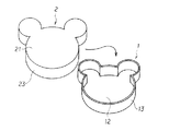
まず本発明の特殊な形状を有する紙製容器を説明する。図1はこの紙製容器の一実施例を蓋を外した状態で示す斜視図で、1は身(下箱)、12はその底板、13はその周囲に立設された胴板、2は蓋(上箱)、21はその蓋板、23はその周囲に立設された胴板である。底板12と蓋板21は相似形で蓋板21がわずかに大きく、いずれもこの例では円形部分の周囲に2か所のこれより小さい円形の突出部があり、その境界部分がするどくくびれた特殊な形状である。
【0011】
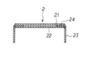
図2は蓋2の断面を示す断面図である。身1と蓋2とは寸法が異なるのみで同一構造であるから、身1の断面もこれと同様である。胴板23の上端が糊代として内側に90度折り曲げられており、糊代部分が見えないように上下を同一形状寸法の2枚の蓋板(上板)21、(下板)22ではさんで糊付けされている。図1では1枚しか見えないが、底板も下板11、上板12の2枚で構成されている。
【0012】
身1にクッキー、チョコレート等の菓子やアクセサリー、ハンカチーフ等を入れ、蓋2をかぶせて店頭に展示すれば、従来の単純な円形や四辺形の容器に比べて注目度が高く、有利に販売することができるものと期待される。
つづいてこの紙製容器の製造方法を説明する。なお、再三説明しているとおり身1と蓋2とは寸法が異なるのみで同一構造であるから、以下これらの一方である蓋を製造する場合について説明する。
【0013】
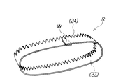
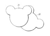
図3は胴板となる胴部リングRを示す斜視図で、Wは胴部リングRの接合部、図4は2枚の蓋板21、22を示す斜視図である。いずれも紙製である。これらを組み合わせ糊付けして蓋2が製作される。なお組み合わせて容器の外側、あるいは蓋の内側になる面には、適宜それにふさわしい着色、あるいは模様などのプリントが施される。
【0014】
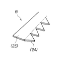
図5は胴部リングRの素材である胴部ブランクBを示す斜視図で、帯状の胴板23の片側側面に糊代24が形成されている。この胴部ブランクBを所定長さに切断する。容器として使用する場合の身と蓋との間隙は少ないほどよいので、身に使用する胴板13と蓋に使用する胴板23とではわずかに長さを変える必要がある。予めCAD等の手法を用いて底板11、蓋板21の周長を正確に求め、これに見合う寸法に切断することが重要である。
【0015】
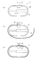
つづいて切断した胴部ブランクBの端部を接合してリング状の胴部リングを製作する。図6は胴部リング製作装置を示す概念図で、(a)は装置の構成を示し、31は端部の接合を行う圧着台、36はリングガイド、37はリングガイドの間隔を調整する胴長調節機である。胴長調節機37を操作してリングガイド36の間隔を調整し、胴部リングRの周長が適切になるようにしておいて(b)に示すようにクランプ33で胴部ブランクBの先端を圧着台31に押さえつけ、胴部ブランクBをリングガイド36の外周に巻き付け、胴部ブランクBの末端をさきの先端に重ね合わせて糊付けし、圧着して図3に示した胴部リングRを製作する。
【0016】
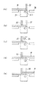
圧着台31における作業を図7によりさらに詳しく説明する。(a)に示すようにまずストッパ32を圧着台31に下降させておいて胴部ブランクBを送り込む。フォトセンサ311 によって先端を検知したら、(b)に示すようにクランプ33を下降させて先端を押さえつける。(c)に示すようにストッパ32を上昇させ、代わりに糊付けヘッド35を下降させて胴部ブランクB先端表面に糊付けする。図6で説明したように胴部ブランクBの末端を先端に重ね、(e)に示すようにプレスヘッド35を下降させて糊付け部分を圧着する。これでリング状の胴部リングができる。
【0017】
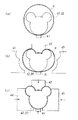
つぎに胴部の成形と、成形された胴板と蓋板との接合を図8により説明する。図8は胴部成形ユニットの平面図で、41は胴部リングRの位置を固定する位置決めヘッド、42は蓋板22と同形の内型である。(a)に示すように、内型42に蓋板(下板)22を載せ、周囲に胴部リングRをかけて位置決めヘッド41で固定する。図3に示した胴部リングRの接合部Wは、容器の正面とか真裏など、見た目の好ましい位置にあることが必要である。成形中にこれが動くことのないよう、 位置決めヘッド41で固定しておくことが望ましい。
【0018】
ついで(b)、(c)に示すように分割された外型43、44、45を順次内型42に向けて移動させ、胴部リングRを内型42に押しつける。
つづいて、外型43、44、45を押しつけたままの状態で、胴部リングRの糊代24を折り曲げる。これを図9により説明する。
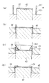
図9は胴部成形ユニットの断面図である。(a)では、内型42の上に下板22が載置され、その周囲に胴部リングRが置かれている。図8の(a)の状態に対応する。ついで(b)に示すように外型44、45が移動して、胴部リングRが内型42に押しつけられる。この状態は図8の(c)に対応する。つぎに上方から折り曲げプレスヘッド541 が下降して、胴部リングRの糊代24を内側に折り曲げる。このとき、内型42はプレスヘッド541 に押されて沈下し、糊代24は90度以上に折り曲げられる。このように90度以上に折り曲げることによって、プレスヘッド541 が離れた後、紙のスプリングバックがあっても、糊代24が胴板23に対して90度折れ曲がっているようにすることが重要である。(d)はプレスヘッド541 が上昇し、内型42も元の高さに復帰した状態である。
【0019】
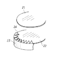
この状態で図示しない糊付けヘッド551 を下降させ、糊代24の上面に糊を付ける。図10はこれにつづいて上板21を載せようとしている状態を示す部分斜視図である。糊代24の上面に塗り付けられた糊は上板21を載せて上方から押されることによって周囲に広がり、広がった糊によって上板21、糊代24、下板22の三者が接合され、容器の蓋2が完成する。
【0020】
この場合、糊としてホットメルト性のものを使用すると、ノズルから流れ出て盛り上がっている状態までは液状であるが、押しつぶされて熱を失うことによってただちに硬化して接着力が発生するので、溶剤の揮発や乾燥のような待ち時間が不要であり、製造能率を向上させることができる。
本発明の特殊な形状を有する紙製容器を製造するのに好適な製造装置の一実施例を図11に示す。
【0021】
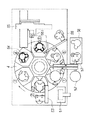
この製造装置では、別途に製作した上下の蓋板(底板)と胴部リングを供給することによって連続的に蓋(下箱)や身(上箱)を製造することができる。図11はこの製造装置の平面図で、4は上面に放射線状に60度間隔で6組の胴部成形ユニットを備えた水平円盤状のターンテーブルで、各ターンテーブルには図8に示した位置決めヘッド41、昇降可能で、底板あるいは蓋板の形状に合わせた外形を有する内型42、この内型42に対して半径方向に接近、離反可能で3分割された外型43、44、45が備えられている。
【0022】
51〜58(5)は周辺機器で、51は胴部リングRを受け入れる受け入れ台、52はこれを1本ずつターンテーブル上の胴部成形ユニットに供給する胴部リング移載機、53は下板を1枚ずつターンテーブル上の胴部成形ユニットに供給する下板移載機、54は糊代折り曲げ装置、55はXY2軸方向に移動して糊代に糊付けを行う糊付けロボット、551 はロボットハンドに取り付けられた糊付けヘッド、56は上板を1枚ずつターンテーブル上の胴部成形ユニットに供給する上板移載機、57はターンテーブル上から出来上がった製品を取り出す製品取り出し機、58は製品を載置する製品台である。
【0023】
図に▲1▼で示したターンテーブル位置でまず胴部成形ユニットに胴部リングRが供給され、ついで時計方向に60度回転した▲2▼の位置で下板12、22が供給され、図8(a)、図9(a)の状態となる。つぎの▲3▼位置で外型が移動して胴部リングRが内型に押しつけられ図8(c)、図9(b)の状態となる。▲4▼の位置に糊代折り曲げ装置54があり、図9(c)に示した折り曲げプレスヘッド541 により糊代の折り曲げが行われる。▲5▼の位置で糊付けヘッド551 により糊付けが行われ、▲6▼で上板11、21が供給され、接合されて製品が出来上がる。
【0024】
以上の説明から明らかなように、本発明の特殊な形状を有する紙製容器の製造方法、あるいは製造装置は、図1に示した形状のものに限らず、複数の屈曲点や曲率変化部を有する胴板を持ち、複雑な平面形状を有するさまざまな紙製容器を自動的に製造することができる。本発明によれば、人気キャラクターや動物、UFO、スポーツカー等といった従来複雑な手作業でしか製造できなかった特殊な形状の紙製容器が自動的に、かつ大量に製造可能となるのである。
【0025】
【発明の効果】
本発明によれば、従来自動化が困難と見られていた凹凸部や曲線等に囲まれた複雑な平面形状を有しながら、自動化した生産設備で大量に製造することを可能とした紙製容器ならびにその製造方法および製造装置が実現することにより、注目度の高いユニークな形状の容器のコストが低下し、製造が効率化されるというすぐれた効果を奏する。
【図面の簡単な説明】
【図1】本発明の紙製容器の実施例を示す斜視図である。
【図2】本発明の紙製容器の実施例における蓋の断面を示す断面図である。
【図3】本発明の紙製容器における胴部リングを示す斜視図である。
【図4】本発明の紙製容器における2枚の蓋板を示す斜視図である。
【図5】本発明の紙製容器における胴部リングの素材である胴部ブランクを示す斜視図である。
【図6】本発明の紙製容器における胴部リングを製作する胴部リング製作装置の概念図である。
【図7】本発明の胴部リング製作装置における圧着台での胴部リング製作作業を説明する概念図である。
【図8】本発明の紙製容器における胴部リングを成形する胴部成形ユニットを示す平面図である。
【図9】本発明の紙製容器における胴部リングを成形する胴部成形ユニットの断面図である。
【図10】本発明の紙製容器における蓋板と胴部リングとの接合作業を示す部分斜視図である。
【図11】本発明の紙製容器を製造する製造装置を示す平面図である。
【符号の説明】
1 身(下箱)
2 蓋(上箱)
3 胴部リング製作装置
4 ターンテーブル
5 周辺機器
11 底板(下板)
12 底板(上板)
13、23 胴板
14、24 糊代
21 蓋板(上板)
22 蓋板(下板)
31 圧着台
32 ストッパ
33 クランプ
34 プレスヘッド
35、551 糊付けヘッド
36 リングガイド
37 胴長調節機
41 位置決めヘッド
42 内型
43、44、45 外型
51 受入れ台
52 胴部リング移載機
53 下板移載機
54 糊代折り曲げ装置
55 糊付けロボット
56 上板移載機
57 製品取り出し機
58 製品台
311 フォトセンサ
541 折り曲げプレスヘッド
B 胴部ブランク
R 胴部リング
W 接合部[0001]
TECHNICAL FIELD OF THE INVENTION
The present invention relates to a paper container having a special shape for accommodating small articles such as cookies, chocolate and other confectionery, accessories, handkerchiefs and the like for sale and a method for producing the same.
Incidentally, a special shape in the present specification refers to a complex shape whose plane shape is not a simple figure such as a circle or a quadrilateral but is surrounded by irregularities, curves, and the like.
[0002]
[Prior art]
In order to store and sell confectionery such as cookies and chocolates, accessories, handkerchiefs and other small articles, paper containers having similar shapes and slightly different sizes and lids are often used. Many of these are simple figures, such as circles and quadrilaterals, so that the steps such as bending and gluing can be easily automated. For example, Japanese Patent Application Laid-Open No. 3-57631 discloses a top part, An automatic apparatus for manufacturing a paper container of milk or juice made by folding a triangular flap at the bottom into a square tubular shape, and Patent Document 2 (Japanese Patent Laid-Open No. 8-142235) discloses a four-sided paper container capable of easily and quickly responding to a change in size. An automatic device for the production of dish-shaped paper containers is described.
[0003]
On the other hand, for example, in the case of a bottle-shaped container or the like in which the neck portion is thinner than the body portion, as shown in Patent Document 3 (Japanese Utility Model Application Laid-Open No. 63-23229), the shape of the paper blank and the folded shape are devised. Attempts are made to facilitate manual assembly, and assembling must be done manually.
[0004]
[Patent Document 1]
Japanese Patent Application Laid-Open No. 3-57631 (page 1-8, Figure 1-14)
[Patent Document 2]
Japanese Patent Application Laid-Open No. 8-142235 (Page 1-13, Figure 26)
[Patent Document 3]
Japanese Utility Model Application Laid-Open No. 63-23229, microfilm (page 1-13, Figure 1-5)
[0005]
[Problems to be solved by the invention]
The present invention has a complicated planar shape surrounded by irregularities and curves that were conventionally considered difficult to automate, while enabling paper containers to be mass-produced by automated production equipment, and It is an object to realize a manufacturing method and a manufacturing apparatus.
[0006]
[Means for Solving the Problems]
A paper container having a special shape according to the present invention is a body made of a bottom plate having a special shape, a body plate erected around the bottom plate, and a lid slightly similar in size to the bottom plate and slightly larger in size. A paper container having a special shape consisting of a plate and a lid consisting of a body plate erected around the lid plate, wherein the bottom plate and the lid plate are two plates each having the same shape and size. And wherein the body plate has a bendable glue allowance and is glued between two plates, the bottom plate and the lid plate.
[0007]
Further, the method for producing a paper container having a special shape according to the present invention is characterized in that a band-shaped trunk blank having a margin on one side is cut to a predetermined length, and the ends are joined to form a ring-shaped trunk ring. And one bottom plate or lid plate is placed on the upper surface of an inner die having an outer shape adapted to the shape of the bottom plate or lid plate, and the body ring is pressed against the outer periphery of the inner die. The glue margin is bent so as to be bent by 90 degrees, glued, and another bottom plate or lid plate is placed on the upper surface and joined.
[0008]
Further, the apparatus for manufacturing a paper container having a special shape according to the present invention includes an inner die having an outer shape adapted to the shape of a bottom plate or a cover plate capable of ascending and descending on the upper surface of a horizontal disk-shaped turntable, and A plurality of body forming units consisting of an outer mold divided into a plurality of parts that can approach and separate in the radial direction are arranged radially, and a lower plate transfer device and a glue bending device are arranged around this turntable. The glue robot, the upper plate transfer device, and the take-out machine are arranged in this order according to the rotation direction of the turntable.
[0009]
BEST MODE FOR CARRYING OUT THE INVENTION
According to the present invention, a body ring whose perimeter is previously adjusted to the plane shape of the container is manufactured, an inner mold is prepared according to the shape of the container, a lower plate is placed on this, and the body ring is placed inside. By pressing the upper plate by pressing it against the mold side and joining it by sandwiching the margin of the body ring between the lower plate and the upper plate, it has a body plate with multiple bending points and curvature changing parts, Paper containers having various planar shapes can be manufactured automatically.
[0010]
【Example】
First, a paper container having a special shape according to the present invention will be described. FIG. 1 is a perspective view showing an embodiment of this paper container with a lid removed, wherein 1 is a body (lower box), 12 is its bottom plate, 13 is a trunk plate erected around it, and 2 is A lid (upper box), 21 is its lid plate, and 23 is a trunk plate erected around it. The
[0011]
FIG. 2 is a sectional view showing a section of the
[0012]
If you put cookie, chocolate and other confectionery and accessories, handkerchiefs, etc. on the body 1, cover it with the
Next, a method for manufacturing the paper container will be described. As described again, the body 1 and the
[0013]
FIG. 3 is a perspective view showing a body ring R serving as a body plate, W is a joint portion of the body ring R, and FIG. 4 is a perspective view showing two
[0014]
FIG. 5 is a perspective view showing a torso blank B which is a material of the torso ring R, and a
[0015]
Subsequently, the cut ends of the body blank B are joined to form a ring-shaped body ring. 6A and 6B are conceptual diagrams showing a body ring manufacturing apparatus, wherein FIG. 6A shows the structure of the apparatus, 31 is a crimping table for joining the ends, 36 is a ring guide, and 37 is a body for adjusting the interval between ring guides. It is a length adjusting machine. The
[0016]
The operation of the crimping table 31 will be described in more detail with reference to FIG. As shown in (a), first, the
[0017]
Next, the formation of the body and the joining of the formed body plate and the cover plate will be described with reference to FIG. FIG. 8 is a plan view of the body forming unit, 41 is a positioning head for fixing the position of the body ring R, and 42 is an inner mold having the same shape as the
[0018]
Next, the outer dies 43, 44, and 45 divided as shown in (b) and (c) are sequentially moved toward the
Subsequently, the
FIG. 9 is a sectional view of the body forming unit. In (a), the
[0019]
In this state, the gluing head 551 (not shown) is lowered to glue the upper surface of the
[0020]
In this case, if a hot-melt adhesive is used, the adhesive is in a liquid state until it flows out of the nozzle and rises up.However, it is immediately cured by crushing and losing heat to generate adhesive force. No waiting time such as volatilization and drying is required, and the production efficiency can be improved.
FIG. 11 shows an embodiment of a manufacturing apparatus suitable for manufacturing a paper container having a special shape according to the present invention.
[0021]
In this manufacturing apparatus, a lid (lower box) and a body (upper box) can be manufactured continuously by supplying upper and lower lid plates (bottom plate) and a body ring which are separately manufactured. FIG. 11 is a plan view of this manufacturing apparatus.
[0022]
51 to 58 (5) are peripheral devices, 51 is a receiving table for receiving the torso ring R, 52 is a torso ring transfer machine for supplying one by one to the torso forming unit on the turntable, and 53 is a lower part. A lower plate transfer machine that supplies the plates one by one to the body forming unit on the turntable, 54 is a glue bending device, 55 is a gluing robot that moves in the XY biaxial directions to glue the glue margin, and 551 is a robot The gluing head attached to the hand, 56 is an upper plate transfer machine that supplies the upper plate one by one to the body forming unit on the turntable, 57 is a product take-out machine that takes out the finished product from the turntable, and 58 is A product table on which products are placed.
[0023]
At the turntable position indicated by (1) in the figure, the body ring R is first supplied to the body forming unit, and then the
[0024]
As is clear from the above description, the method or apparatus for manufacturing a paper container having a special shape of the present invention is not limited to the shape shown in FIG. A variety of paper containers having a complicated plane shape can be automatically manufactured. According to the present invention, paper containers having a special shape, such as popular characters, animals, UFOs, sports cars, and the like, which can be manufactured only by complicated manual operations, can be automatically and mass-produced.
[0025]
【The invention's effect】
According to the present invention, a paper container that can be mass-produced by an automated production facility while having a complicated planar shape surrounded by irregularities, curves, and the like, which has conventionally been considered difficult to automate. In addition, the realization of the manufacturing method and the manufacturing apparatus thereof has an excellent effect that the cost of a container having a unique shape with a high degree of attention is reduced, and the manufacturing is made more efficient.
[Brief description of the drawings]
FIG. 1 is a perspective view showing an embodiment of a paper container according to the present invention.
FIG. 2 is a cross-sectional view showing a cross section of a lid in the embodiment of the paper container of the present invention.
FIG. 3 is a perspective view showing a body ring in the paper container of the present invention.
FIG. 4 is a perspective view showing two lid plates in the paper container of the present invention.
FIG. 5 is a perspective view showing a trunk blank which is a raw material of a trunk ring in the paper container of the present invention.
FIG. 6 is a conceptual diagram of a body ring manufacturing apparatus for manufacturing a body ring in a paper container of the present invention.
FIG. 7 is a conceptual diagram illustrating a body ring manufacturing operation using a crimping table in the body ring manufacturing apparatus of the present invention.
FIG. 8 is a plan view showing a body forming unit for forming a body ring in the paper container of the present invention.
FIG. 9 is a sectional view of a body forming unit for forming a body ring in the paper container of the present invention.
FIG. 10 is a partial perspective view showing the joining operation of the lid plate and the trunk ring in the paper container of the present invention.
FIG. 11 is a plan view showing a manufacturing apparatus for manufacturing the paper container of the present invention.
[Explanation of symbols]
1 body (lower box)
2 lid (upper box)
3 torso
12 Bottom plate (top plate)
13, 23
22 lid plate (lower plate)
31 Crimping table 32
Claims (3)
Priority Applications (1)
| Application Number | Priority Date | Filing Date | Title |
|---|---|---|---|
| JP2002274998A JP2004106916A (en) | 2002-09-20 | 2002-09-20 | Paper container having special shape and method of manufacturing the same |
Applications Claiming Priority (1)
| Application Number | Priority Date | Filing Date | Title |
|---|---|---|---|
| JP2002274998A JP2004106916A (en) | 2002-09-20 | 2002-09-20 | Paper container having special shape and method of manufacturing the same |
Publications (1)
| Publication Number | Publication Date |
|---|---|
| JP2004106916A true JP2004106916A (en) | 2004-04-08 |
Family
ID=32271323
Family Applications (1)
| Application Number | Title | Priority Date | Filing Date |
|---|---|---|---|
| JP2002274998A Pending JP2004106916A (en) | 2002-09-20 | 2002-09-20 | Paper container having special shape and method of manufacturing the same |
Country Status (1)
| Country | Link |
|---|---|
| JP (1) | JP2004106916A (en) |
Cited By (1)
| Publication number | Priority date | Publication date | Assignee | Title |
|---|---|---|---|---|
| JP2009519843A (en) * | 2005-12-19 | 2009-05-21 | テトラ ラバル ホールデイングス エ フイナンス ソシエテ アノニム | Method and apparatus for applying an adhesive to a spout for bonding the spout to a pourable food package |
-
2002
- 2002-09-20 JP JP2002274998A patent/JP2004106916A/en active Pending
Cited By (2)
| Publication number | Priority date | Publication date | Assignee | Title |
|---|---|---|---|---|
| JP2009519843A (en) * | 2005-12-19 | 2009-05-21 | テトラ ラバル ホールデイングス エ フイナンス ソシエテ アノニム | Method and apparatus for applying an adhesive to a spout for bonding the spout to a pourable food package |
| US9457378B2 (en) | 2005-12-19 | 2016-10-04 | Tetra Laval Holdings & Finance S.A | Method of applying adhesive to opening devices for gluing to sealed packages of pourable food products |
Similar Documents
| Publication | Publication Date | Title |
|---|---|---|
| EP0395585B1 (en) | Method of manufacturing labeled objects. method of manufacturing labelled containers utilizing said method, and labeling preformer apparatus for use in carrying out the method | |
| ES2398901T4 (en) | Device, apparatus and process for wrapping an article in a sheet wrap | |
| CA2562150A1 (en) | Paper wrapped foam cup and method of assembly | |
| HU215053B (en) | Method and device for packing of product in foil | |
| CN1039693C (en) | Multiple structure paper protection body and its manufacturing device | |
| US3877139A (en) | Glassless mirror | |
| JP2004106916A (en) | Paper container having special shape and method of manufacturing the same | |
| JPH08318926A (en) | Method and apparatus for manufacturing paper dish-shaped container | |
| JP3886500B2 (en) | Paper tray molding equipment | |
| TWI888046B (en) | A compound cup pressing mechanism | |
| GB2103538A (en) | Making drums for packaging | |
| JP7503772B2 (en) | container | |
| EP1422052B1 (en) | Procedure for construction of multi-layer cylindrical containers and containers so obtained | |
| JP7437752B2 (en) | Kagami-mochi decoration assembly device and method for manufacturing kagami-mochi decorations | |
| JP2551789B2 (en) | How to decorate the container | |
| JPH07119076B2 (en) | Sheet material drawing equipment | |
| JP2002254534A (en) | Method for molding paper product | |
| US5901841A (en) | Container, method of filling and closing, and blank used to form the container | |
| JPS61217343A (en) | Packaging paperboard carton and manufacture thereof | |
| JPH04282235A (en) | Drawing apparatus | |
| JP2004122410A (en) | Paper sheet molding | |
| JP3035795U (en) | Sealing material for wrapping paper | |
| CN107901592A (en) | Air-inlet grille foil stamping process and the automation thermoprint assembly line using the technique | |
| JP2006281487A (en) | Simple forming apparatus for cylindrical paper container and method for forming the same | |
| JP3047349U (en) | Coloring sheet |
Legal Events
| Date | Code | Title | Description |
|---|---|---|---|
| A621 | Written request for application examination |
Free format text: JAPANESE INTERMEDIATE CODE: A621 Effective date: 20040517 |
|
| A977 | Report on retrieval |
Free format text: JAPANESE INTERMEDIATE CODE: A971007 Effective date: 20060314 |
|
| A131 | Notification of reasons for refusal |
Free format text: JAPANESE INTERMEDIATE CODE: A131 Effective date: 20060322 |
|
| A521 | Written amendment |
Free format text: JAPANESE INTERMEDIATE CODE: A523 Effective date: 20060519 |
|
| A02 | Decision of refusal |
Free format text: JAPANESE INTERMEDIATE CODE: A02 Effective date: 20061219 |