JP2004106947A - Tape crimping device with parallel function of two planes - Google Patents
Tape crimping device with parallel function of two planes Download PDFInfo
- Publication number
- JP2004106947A JP2004106947A JP2002267863A JP2002267863A JP2004106947A JP 2004106947 A JP2004106947 A JP 2004106947A JP 2002267863 A JP2002267863 A JP 2002267863A JP 2002267863 A JP2002267863 A JP 2002267863A JP 2004106947 A JP2004106947 A JP 2004106947A
- Authority
- JP
- Japan
- Prior art keywords
- teeth
- holder
- tape
- sphere
- lower teeth
- Prior art date
- Legal status (The legal status is an assumption and is not a legal conclusion. Google has not performed a legal analysis and makes no representation as to the accuracy of the status listed.)
- Pending
Links
Images


Landscapes
- Folding Of Thin Sheet-Like Materials, Special Discharging Devices, And Others (AREA)
Abstract
【課題】従来の構造では、上歯と下歯の対向面の平行出しの操作が面倒で多くの時間を要するうえ、精度よく調整するのが困難であった。
【解決手段】少なくとも一部に球面部72を有する球体70と、上面を開口したホルダー30と、弾性部材60とを備える。ホルダー30の開口部内に取付けた下歯40を上下動自在に弾性部材60で支持するとともに、ホルダー30の内底面に凹部33を形成する。球面部72の一部を凹部33の中に挿入して、球体70をホルダー30と下歯40の間に取付ける。圧着動作時には、上歯50下面の上歯面51の傾斜に追随して下歯40が傾き、テープに接触する上歯面51と下歯面41とが平行になる。
【選択図】 図1With the conventional structure, the operation of parallelizing the opposing surfaces of the upper teeth and the lower teeth is troublesome and requires a lot of time, and it is difficult to perform the adjustment with high accuracy.
A sphere having a spherical portion at least in part, a holder having an open upper surface, and an elastic member are provided. The lower teeth 40 mounted in the opening of the holder 30 are supported by the elastic member 60 so as to be vertically movable, and a concave portion 33 is formed on the inner bottom surface of the holder 30. A part of the spherical part 72 is inserted into the concave part 33, and the spherical body 70 is mounted between the holder 30 and the lower teeth 40. At the time of the pressure bonding operation, the lower teeth 40 are inclined following the inclination of the upper teeth 51 of the lower surface of the upper teeth 50, and the upper teeth 51 and the lower teeth 41 that come into contact with the tape become parallel.
[Selection diagram] Fig. 1
Description
【0001】
【発明の属する技術分野】
本発明は、面付け型の電子部品をキャリアテープにテーピング包装する場合などに用いられ、二枚のテープを加圧して接合するテープ圧着装置の構造に関するものである。
【0002】
【従来の技術】
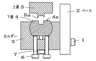
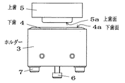
対向面に接着剤を塗布した二枚のテープを加圧して接合したり、あるいは加熱しながら加圧して熱圧着するテープ圧着装置が用いられている。この種のテープ圧着装置の従来例を図7及び図8に示す。ボルト1でベース2に固定されたホルダー3には下歯4が回動可能に取付けられ、下歯4の上方には上歯5が上下動自在に設けられている。下歯4と上歯5には、それぞれ下歯面4aと上歯面5aを対向させて設けてある。下歯面4aと上歯面5aは、下歯4と上歯5で二枚のテープを挟んだときテープに直接接触する部分である。
【0003】
上下に重ねて供給されたキャリアテープとカバーテープを下歯4と上歯5で挟んで圧着する場合、確実に接合するためには下歯面4aと上歯面5aの二平面が互いに平行であることが必要である。この従来のテープ圧着装置では、この平行出しを次のようにして行っている。
【0004】
まず、2本のボルト6によって図7で左右方向の平行合わせを行った後、ボルト7を締め付けて下歯4をホルダー3に固定する。次にボルト1を緩めてホルダー3の図7で奥行き方向の平行を合わせた後、ボルト1を締め付けてホルダー3を固定することで行っていた。
【0005】
【発明が解決しようとする課題】
このように、従来の構造では平行出しの操作が面倒で多くの時間を要し、精度よく調整するのが困難であった。しかも、下歯4や上歯5は交換頻度の高い消耗部品であり、これらを交換したときや歯先が消耗して変形したときなど、頻繁に下歯4の姿勢の修正が必要となっていた。
【0006】
また、平行出しの別の手段として、特開平9−5054号公報に記載のような方法も考えられている。これは上歯と下歯の間に透過光を照射する装置を付加し、発生する干渉縞を利用して二平面の平行出しを行うものである。しかし、この方法では装置が複雑で大型化するうえ、高価になる問題があった。
【0007】
本発明は、簡単な変更だけで極めてコンパクトに構成できる二平面の平行出し機能を備えたテープ圧着装置を提供することを目的とする。
【0008】
【課題を解決するための手段】
本発明は、上歯面が第1の平面上にある上歯と、この上歯面に対向する下歯面が第2の平面上にある下歯とを有し、二枚のテープを上歯面と下歯面とで挟んで圧着するテープ圧着装置において、圧着動作時に第1の平面と第2の平面が自動的に平行に調整されるようにしたものである。
すなわち本発明によるテープ圧着装置は、少なくとも一部に球面部72を有する球体70と、上面を開口したホルダー30と、弾性部材60とを備え、ホルダー30の開口部内に取付けた下歯40を上下動自在に弾性部材60で支持するとともに、互いに対向したホルダー30の内底面または下歯40の下面の少なくとも一方の面に凹部33、43を形成し、球面部72の一部を凹部33、43の中に挿入して球体70をホルダー30と下歯40の間に取付けた構成を特徴とする。
【0009】
【実施例】
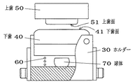
図1及び図2は本発明の第1実施例を示している。上面を開口したホルダー30がベース2に固定してあり、ホルダー30の開口部31の中には下歯40が上方から挿入して取付けてある。下歯40はコイルスプリング60によって上下動自在に支持されている。ホルダー30の中で下歯40が小さな角度傾くことが出来るように、下歯40とホルダー30の間には隙間が設けてある。ホルダー30の上部には下歯40の抜け止め用のストッパー32が取付けられている。
【0010】
ホルダー30の内底面の中央には球面状の凹部33が形成してある。ホルダー30の内底面と下歯40の間には球体70が取付けてある。この球体70は球の上部を平面状に切除して平面部71を設けた形状をしており、平面部71以外の部分は球面部72となっている。球体70は球面部72の一部を凹部33内に挿入してホルダー30の内底面に載置するとともに、偏平な下歯40の下面に平面部71を対向させてある。
【0011】
下歯40の上端には平面状の下歯面41が設けてあり、下歯面41の中央には溝42が切ってある。上方に取付けた上歯50には、先端が平面状をした二つの上歯面51を下方に突出させて設けてある。上歯面51は下歯40の下歯面41に対向した位置にある。図示は省略してあるが、上歯50もベース2に取付けられており、上下動自在になされている。また、上歯50はヒーターを内蔵している。
【0012】
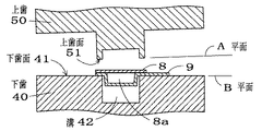
図3は、このテープ圧着装置の使用状態を示している。キャリアテープ8が下歯40の下歯面41の上に載置され、キャリアテープ8のポケット部8aは下歯40の溝42の中に落とし込まれている。ポケット部8aには図示しない電子部品が収容されている。そして、キャリアテープ8に接合されるカバーテープ9がキャリアテープ8上に載置してある。
【0013】
二つの上歯面51は第1の平面A上にあり、下歯面41は第2の平面B上に位置している。カバーテープ9とキャリアテープ8は、下降した上歯面51と下歯面41の間に噛み込まれ、上歯50で加熱されて熱圧着される。カバーテープ9とキャリアテープ8が全体に渡ってムラなく熱圧着されるためには、圧着時に平面Aと平面Bとが平行であることが必要である。この二平面が平行でないと、上歯面51の一部がカバーテープ9から浮いた状態となり、圧着状態が不十分になる。
【0014】
次に、本装置における二平面の平行出し機能について、キャリアテープ8とカバーテープ9を省略して図1を参照して説明する。今、図3の平面Aと平面Bが平行でない場合を考える。図1の状態から上歯50を徐々に下降させると、上歯面51が下歯面41に接触して下歯40を押し下げる。すると、コイルスプリング60で支持されていた下歯40は上歯50に追随して傾くので、上歯面51と下歯面41は平行になる。すなわち、図3における平面Aと平面Bが平行になる。このとき上歯50に加わる応力はコイルスプリング60の反発力となる。
【0015】
さらに押し下げられた下歯40は球体70の平面部71に突き当たる。球体70は下歯40の底面の傾きに追随して回動して傾き、下歯40の底面と平面部71が密着した時点で最終的に二平面の平行出しが完了する。このとき、上歯50による所定の強さの圧力が下歯40と上歯50間に挟まれたテープに加わることになる。
【0016】
ホルダー30は、図4に示すように二つの部材30a、30bを組み合わせて構成してもよい。第1の部材30aは上端に凹部33を形成したもので、周囲に雄ねじを切ったボルト状のものを使用できる。この第1の部材30aは、第2の部材30bの底面に設けた貫通孔35に螺合するか又は嵌合する。36は第1の部材30aを第2の部材30bに固定するためのボルトである。図4に示すように、球体70と下歯40の間に隙間を設けず、両者を当接させた構造としてもよい。
【0017】
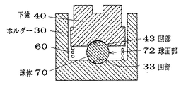
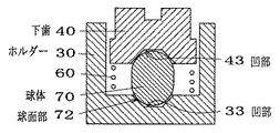
また、図5や図6に示すように、上部及び下部に球面部72を有する球体70を用い、ホルダー30と下歯40の対向面にそれぞれ凹部33、凹部43を設けた構成としてもよい。図5は切除してない球を球体70に使用し、球面状の凹部33、43をホルダー30の内底面と下歯40の下面に形成した例である。図6は円柱の上下端に球面部72を有する球体70を用い、ホルダー30と下歯40の対向面にそれぞれ円錐形の凹部33、43を形成したものである。
【0018】
なお、下歯40は上下動自在に弾性的に支持されていればよく、コイルスプリング60は他の弾性部材、例えば筒状のゴムからなる弾性部材に代えてもよい。下歯面41の溝42は、平面状のテープを使用する場合などは設ける必要がない。本発明は、キャリアテープとカバーテープの圧着に限らず、他の種類のテープの圧着にも適用できる。
【0019】
【発明の効果】
本発明によるテープ圧着装置では、テープに当接する上歯面51と下歯面41の平行出しがテープ圧着時に自動的に行われるので、下歯や上歯を交換したときの平行調整工数を削減できる。また、部品の寸法のバラツキを吸収でき、上歯や下歯が多少磨耗したときでも安定した接合結果を得ることができる。
【図面の簡単な説明】
【図1】本発明のテープ圧着装置の第1実施例を示す一部断面側面図
【図2】同装置の一部切欠正面図
【図3】同装置の使用状態を拡大して示す側面断面図
【図4】本発明の第2実施例を示す要部の側面断面図
【図5】本発明の第3実施例を示す要部の側面断面図
【図6】本発明の第4実施例を示す要部の側面断面図
【図7】従来のテープ圧着装置の一部断面側面図
【図8】同装置の正面図
30 ホルダー
33 凹部
40 下歯
41 下歯面
50 上歯
51 上歯面
70 球体
72 球面部[0001]
TECHNICAL FIELD OF THE INVENTION
The present invention relates to a structure of a tape crimping apparatus used for taping and packaging an imposition type electronic component on a carrier tape and for pressing and joining two tapes.
[0002]
[Prior art]
2. Description of the Related Art A tape crimping apparatus has been used in which two tapes each having an adhesive applied to an opposing surface are pressurized and joined, or are heated and pressurized and thermocompressed. FIGS. 7 and 8 show a conventional example of this type of tape crimping apparatus. Lower teeth 4 are rotatably mounted on a
[0003]
When the carrier tape and the cover tape supplied one above the other are sandwiched between the lower teeth 4 and the upper teeth 5 and pressure-bonded, the two planes of the
[0004]
First, after the two
[0005]
[Problems to be solved by the invention]
As described above, in the conventional structure, the paralleling operation is troublesome and requires a lot of time, and it is difficult to perform the adjustment with high accuracy. In addition, the lower teeth 4 and the upper teeth 5 are consumable parts that are frequently replaced, and the posture of the lower teeth 4 needs to be frequently corrected when these are replaced or when the tip is worn out and deformed. Was.
[0006]
Further, as another means for parallelizing, a method as described in JP-A-9-5054 has been considered. In this method, a device for irradiating transmitted light between the upper teeth and the lower teeth is added, and two planes are parallelized using generated interference fringes. However, this method has a problem that the apparatus is complicated and large, and is expensive.
[0007]
SUMMARY OF THE INVENTION An object of the present invention is to provide a tape crimping apparatus having a function of parallelizing two planes which can be extremely compactly configured by simple changes.
[0008]
[Means for Solving the Problems]
The present invention has an upper tooth having an upper tooth surface on a first plane, and a lower tooth having a lower tooth surface facing the upper tooth surface on a second plane. In a tape crimping apparatus for crimping between a tooth surface and a lower tooth surface, a first plane and a second plane are automatically adjusted to be parallel during a crimping operation.
That is, the tape crimping device according to the present invention includes a sphere 70 having a spherical portion 72 at least in part, a holder 30 having an open upper surface, and an
[0009]
【Example】
1 and 2 show a first embodiment of the present invention. A holder 30 having an open upper surface is fixed to the base 2, and
[0010]
A spherical concave portion 33 is formed in the center of the inner bottom surface of the holder 30. A sphere 70 is mounted between the inner bottom surface of the holder 30 and the
[0011]
A flat lower tooth surface 41 is provided at the upper end of the
[0012]
FIG. 3 shows a use state of the tape crimping device. The
[0013]
The two
[0014]
Next, the parallel setting function of the two planes in the present apparatus will be described with reference to FIG. 1 omitting the
[0015]
The
[0016]
The holder 30 may be configured by combining two members 30a and 30b as shown in FIG. The first member 30a has a concave portion 33 formed at the upper end, and can be a bolt-shaped member having a male thread cut around the first member 30a. The first member 30a is screwed or fitted into a through hole 35 provided on the bottom surface of the second member 30b. 36 is a bolt for fixing the first member 30a to the second member 30b. As shown in FIG. 4, a structure may be adopted in which a gap is not provided between the spherical body 70 and the
[0017]
Alternatively, as shown in FIGS. 5 and 6, a configuration may be used in which a sphere 70 having a spherical portion 72 on the upper and lower portions is used, and the concave portion 33 and the concave portion 43 are provided on the opposing surfaces of the holder 30 and the
[0018]
The
[0019]
【The invention's effect】
In the tape crimping device according to the present invention, since the
[Brief description of the drawings]
FIG. 1 is a partially sectional side view showing a first embodiment of a tape crimping device of the present invention. FIG. 2 is a partially cutaway front view of the device. FIG. 3 is a side sectional view showing an enlarged state of use of the device. FIG. 4 is a side sectional view of a main part showing a second embodiment of the present invention. FIG. 5 is a side cross sectional view of a main part showing a third embodiment of the present invention. FIG. 6 is a fourth embodiment of the present invention. FIG. 7 is a partial cross-sectional side view of a conventional tape crimping device. FIG. 8 is a front view of the same device. 30 Holder 33
Claims (4)
Priority Applications (1)
| Application Number | Priority Date | Filing Date | Title |
|---|---|---|---|
| JP2002267863A JP2004106947A (en) | 2002-09-13 | 2002-09-13 | Tape crimping device with parallel function of two planes |
Applications Claiming Priority (1)
| Application Number | Priority Date | Filing Date | Title |
|---|---|---|---|
| JP2002267863A JP2004106947A (en) | 2002-09-13 | 2002-09-13 | Tape crimping device with parallel function of two planes |
Publications (1)
| Publication Number | Publication Date |
|---|---|
| JP2004106947A true JP2004106947A (en) | 2004-04-08 |
Family
ID=32266245
Family Applications (1)
| Application Number | Title | Priority Date | Filing Date |
|---|---|---|---|
| JP2002267863A Pending JP2004106947A (en) | 2002-09-13 | 2002-09-13 | Tape crimping device with parallel function of two planes |
Country Status (1)
| Country | Link |
|---|---|
| JP (1) | JP2004106947A (en) |
Cited By (4)
| Publication number | Priority date | Publication date | Assignee | Title |
|---|---|---|---|---|
| JP2007137426A (en) * | 2005-11-14 | 2007-06-07 | Ueno Seiki Kk | Taping device and its controlling method |
| JP2008007173A (en) * | 2006-06-30 | 2008-01-17 | Apic Yamada Corp | Pressure-bonding device and taping apparatus |
| KR20170033391A (en) * | 2014-07-22 | 2017-03-24 | 알파 어셈블리 솔루션스 인크. | Stretchable interconnects for flexible electronic surfaces |
| JP2022041083A (en) * | 2020-08-31 | 2022-03-11 | 株式会社 東京ウエルズ | Thermo-compression bonding device of carrier tape, thermo-compression bonding device system of carrier tape and thermo-compression bonding method of carrier tape |
-
2002
- 2002-09-13 JP JP2002267863A patent/JP2004106947A/en active Pending
Cited By (9)
| Publication number | Priority date | Publication date | Assignee | Title |
|---|---|---|---|---|
| JP2007137426A (en) * | 2005-11-14 | 2007-06-07 | Ueno Seiki Kk | Taping device and its controlling method |
| JP2008007173A (en) * | 2006-06-30 | 2008-01-17 | Apic Yamada Corp | Pressure-bonding device and taping apparatus |
| KR20170033391A (en) * | 2014-07-22 | 2017-03-24 | 알파 어셈블리 솔루션스 인크. | Stretchable interconnects for flexible electronic surfaces |
| KR102192757B1 (en) * | 2014-07-22 | 2020-12-18 | 알파 어셈블리 솔루션스 인크. | Stretchable interconnects for flexible electronic surfaces |
| US11139089B2 (en) | 2014-07-22 | 2021-10-05 | Alpha Assembly Solutions Inc. | Stretchable interconnects for flexible electronic surfaces |
| US11830640B2 (en) | 2014-07-22 | 2023-11-28 | Alpha Assembly Solutions, Inc. | Stretchable interconnects for flexible electronic surfaces |
| US12278022B2 (en) | 2014-07-22 | 2025-04-15 | Alpha Assembly Solutions Inc. | Stretchable interconnects for flexible electronic surfaces |
| JP2022041083A (en) * | 2020-08-31 | 2022-03-11 | 株式会社 東京ウエルズ | Thermo-compression bonding device of carrier tape, thermo-compression bonding device system of carrier tape and thermo-compression bonding method of carrier tape |
| JP7383294B2 (en) | 2020-08-31 | 2023-11-20 | 株式会社 東京ウエルズ | Carrier tape thermocompression bonding device, carrier tape thermocompression bonding device system, and carrier tape thermocompression bonding method |
Similar Documents
| Publication | Publication Date | Title |
|---|---|---|
| US8025087B2 (en) | Ultrasonic vibration welder | |
| WO1997043885A1 (en) | Connection base | |
| JPH0955449A (en) | IC carrier | |
| JP2004106947A (en) | Tape crimping device with parallel function of two planes | |
| KR20230142477A (en) | Insert holder and cutting tool assembly with same | |
| JP2006114343A (en) | Manufacturing method of electric wire with terminal | |
| US20040226146A1 (en) | Headband adjustment device | |
| US20070274669A1 (en) | Fabrication tool for bonding | |
| TW201341093A (en) | Ultrasonic welding structure and ultrasonic welding method | |
| JP2018171888A (en) | Belt joining device | |
| JP6603379B2 (en) | Slider structure and method for forming slider structure | |
| CN212526420U (en) | PCB clamping jig with quick buckling structure | |
| JPH0338033B2 (en) | ||
| CN211867209U (en) | Inclined pressing fixing structure and positioning fixture | |
| US5335842A (en) | Self-aligning single point bonding tool | |
| CN100422755C (en) | Chip burning seat | |
| JP6989149B2 (en) | Parts mounting structure, parts mounting mating member, parts fixing member, and parts fixing method | |
| JP2953926B2 (en) | Method and apparatus for joining two plate materials | |
| JP2731061B2 (en) | Button transport unit of button mounting machine | |
| CN119457651B (en) | Fiber optic cutting clamping fixtures and laser cutting equipment | |
| JP3617485B2 (en) | Electronic component bonding apparatus and bonding tool | |
| CN110340526B (en) | Assembly welding set based on powder metallurgy product | |
| JP2006128486A (en) | Ultrasonic mounting method for electronic components | |
| CN214544967U (en) | Workpiece fixing jig | |
| KR200374204Y1 (en) | Fixing apparatus of glasses lens |
Legal Events
| Date | Code | Title | Description |
|---|---|---|---|
| A621 | Written request for application examination |
Free format text: JAPANESE INTERMEDIATE CODE: A621 Effective date: 20031222 |
|
| RD05 | Notification of revocation of power of attorney |
Effective date: 20031222 Free format text: JAPANESE INTERMEDIATE CODE: A7425 |
|
| A977 | Report on retrieval |
Effective date: 20051024 Free format text: JAPANESE INTERMEDIATE CODE: A971007 |
|
| A131 | Notification of reasons for refusal |
Free format text: JAPANESE INTERMEDIATE CODE: A131 Effective date: 20051101 |
|
| A02 | Decision of refusal |
Free format text: JAPANESE INTERMEDIATE CODE: A02 Effective date: 20060307 |